
Optimising the Particulate Emission Characteristics of a Dual-Fuel Spark Ignition Engine by Changing the Gasoline Direct Injection Strategy

 ,
, 


Abstract
:1. Introduction
2. Experimental Methodology
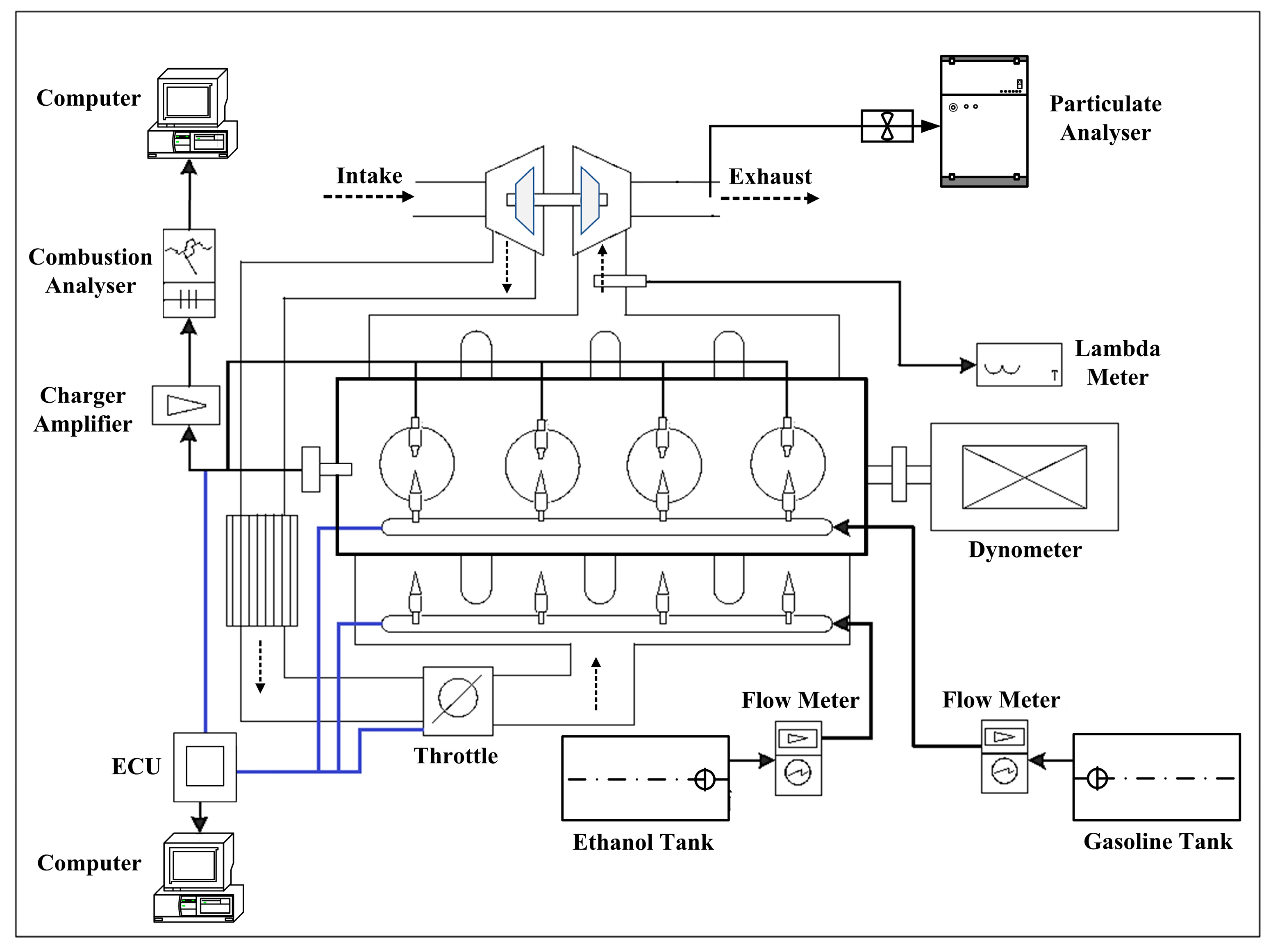
2.1. Experimental Setup
2.2. Experimental Procedure
3. Results and Discussion
3.1. Optimising Particulate Emission Characteristics by Changing GDI Pressure
3.2. Optimising Particulate Emission Characteristics by Using the Split GDI Strategy with Different Second Injection Timings
4. Conclusions
- (1)
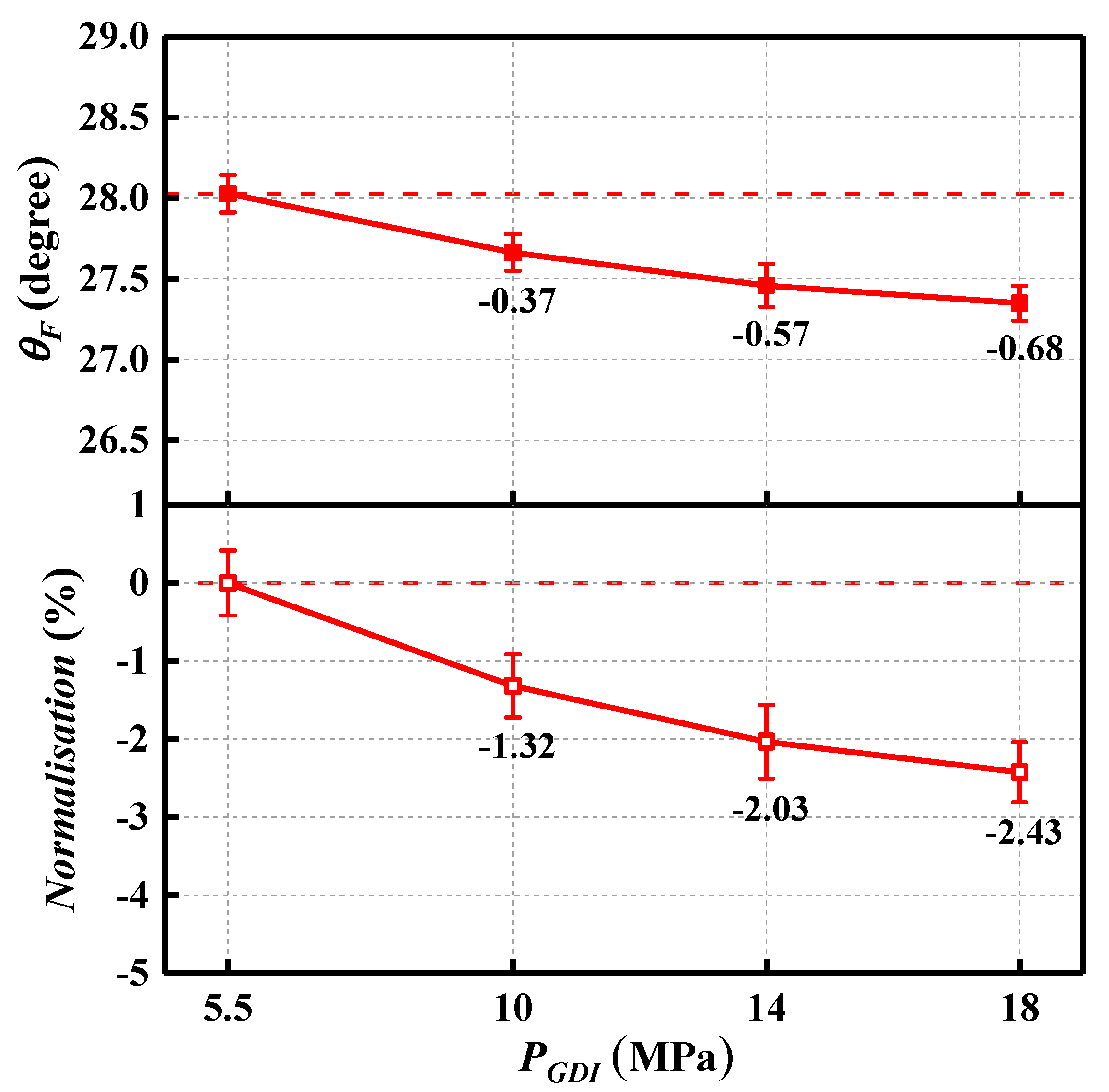
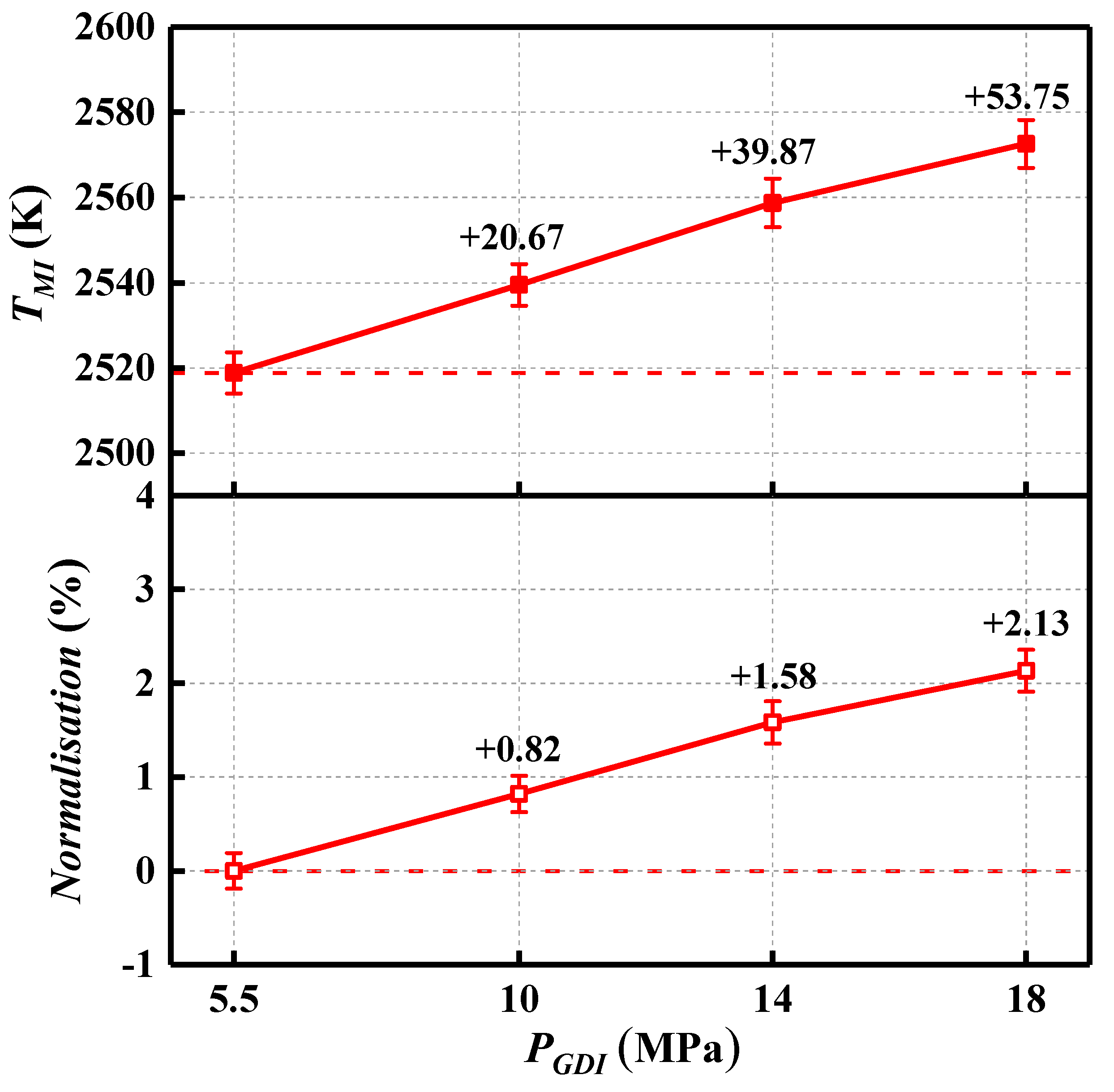
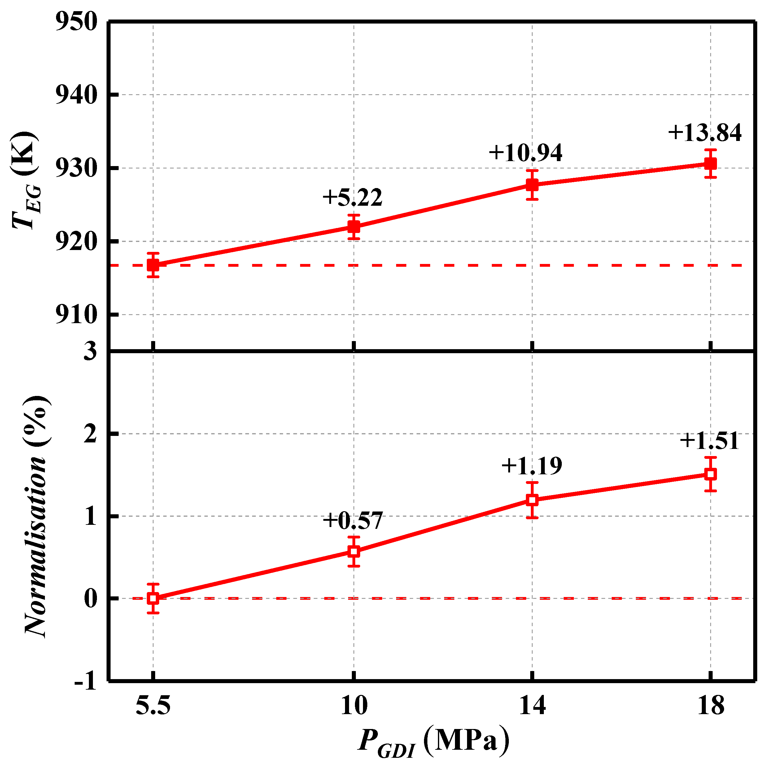
- By increasing from 5.5 MPa to 18 MPa, has a moderate reduction of 0.68 degrees, while and show a growth of 53.75 K and 13.84 K, respectively.
- (2)
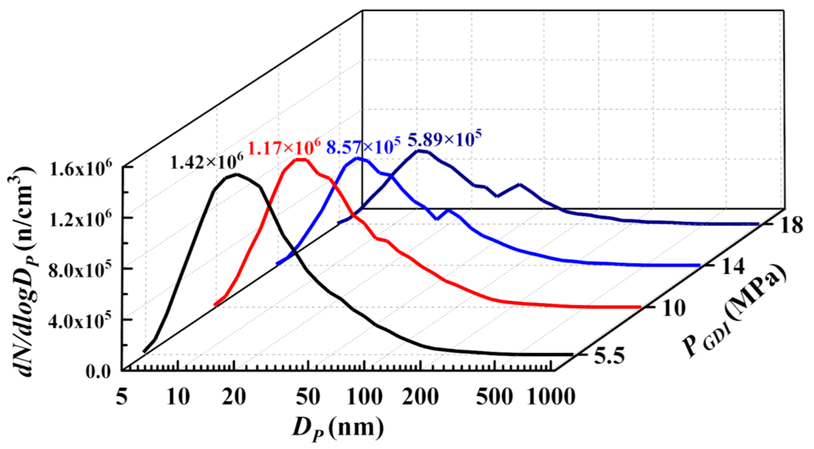
- The peak value of the size distribution curve decreases from 1.42 × 10⁶ to 5.89 × 10⁵ with the increases in from 5.5 MPa to 18 MPa.
- (3)
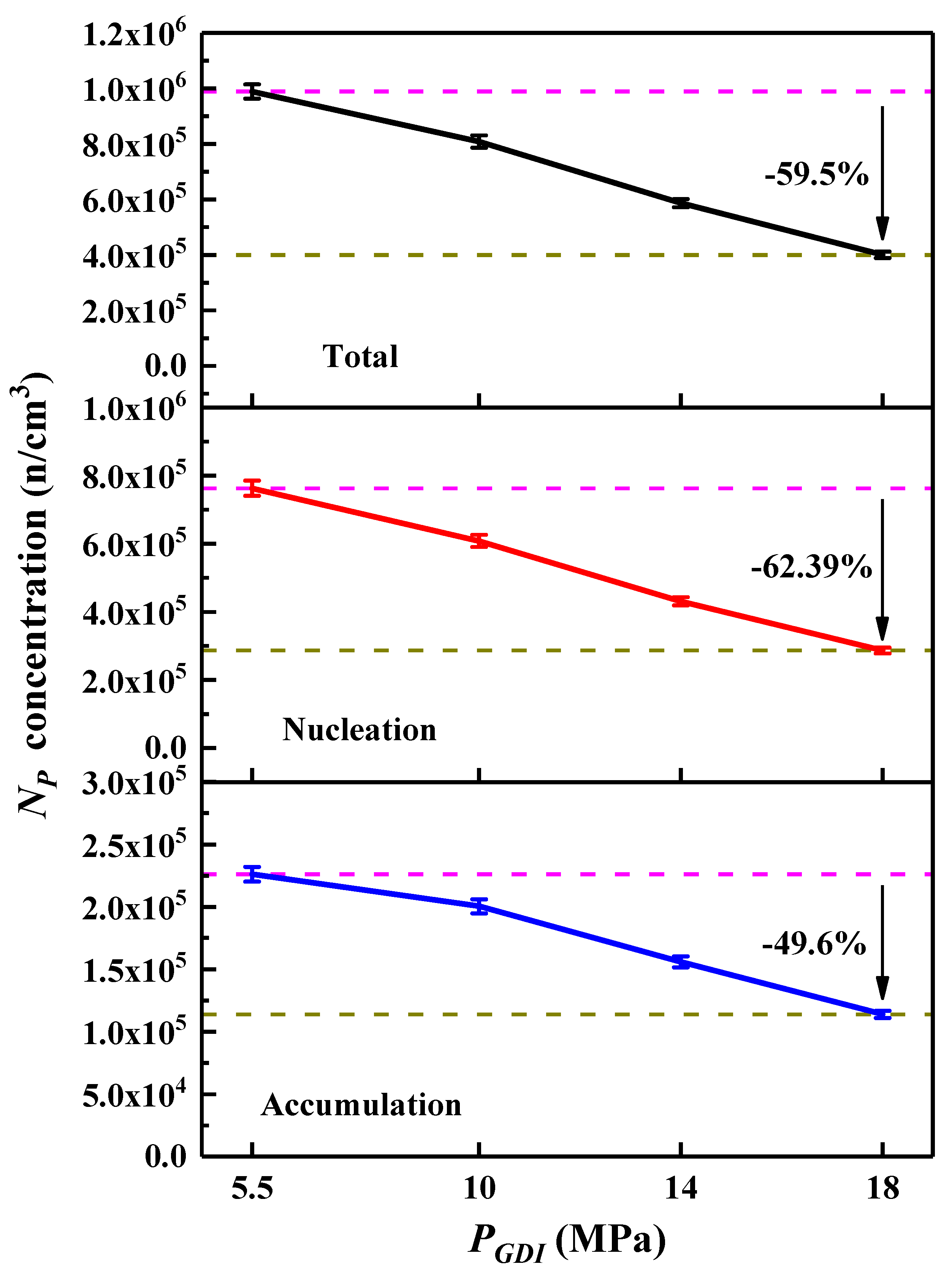
- Positive impacts on the concentrations of and can be provided by increasing . Compared to the condition of = 5.5 MPa, the reduction in and for total particulates can be 59.5% and 36.26% under = 18 MPa.
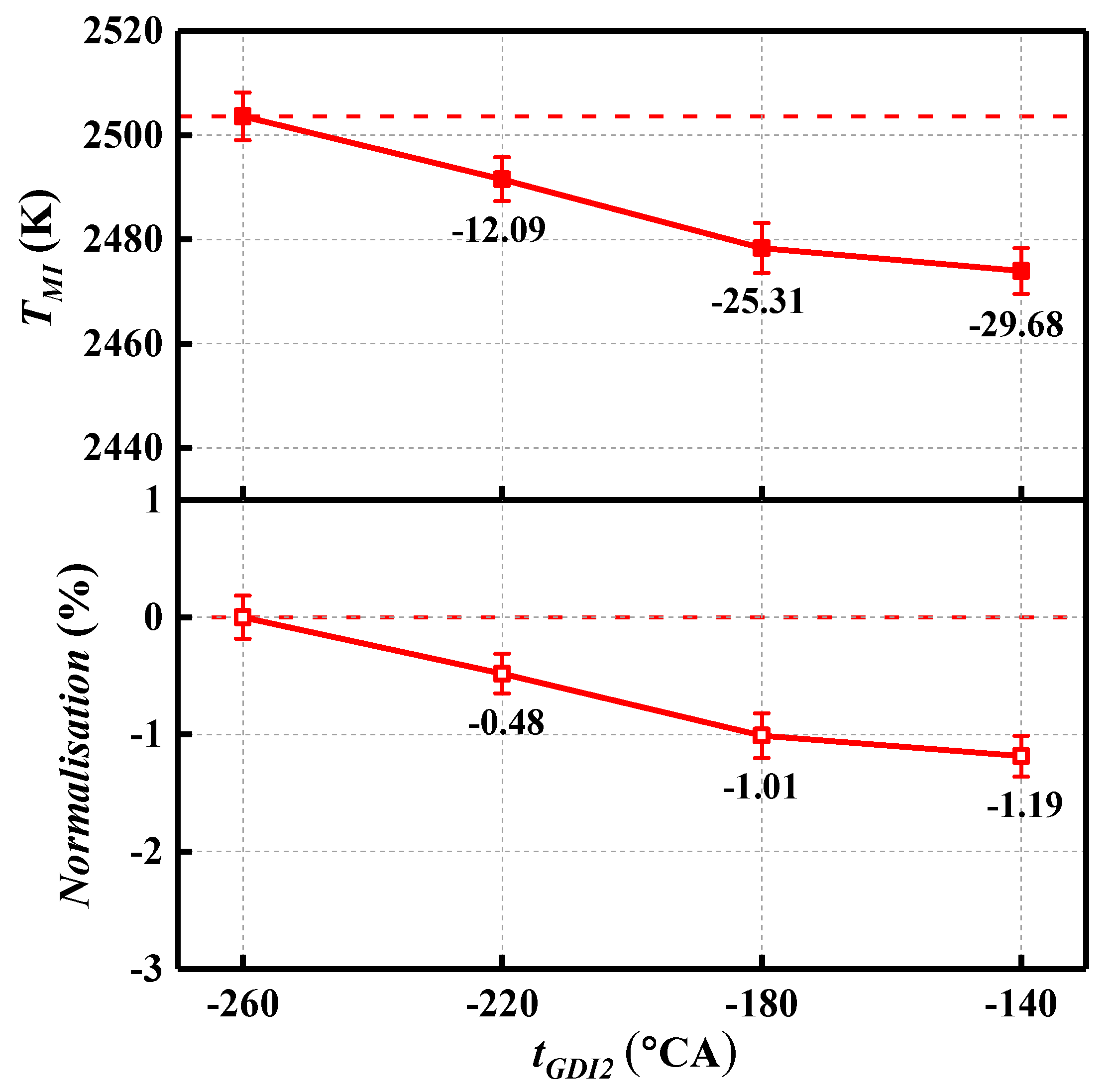
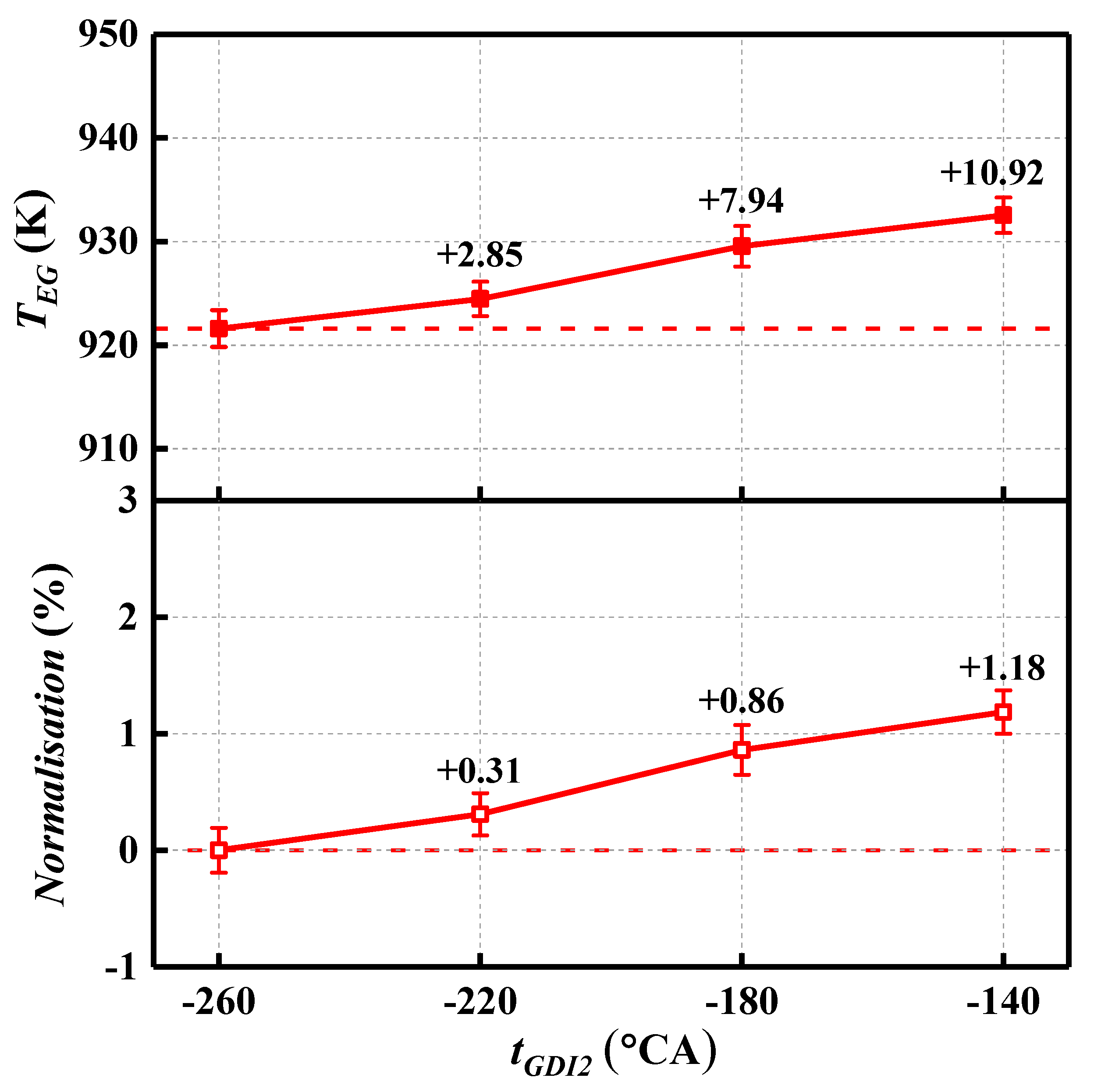
- (4)
- By delaying from −260 °CA to −140 °CA, increases by 0.73 degrees. Further, shows a steady rise from 921.61 K to 932.53 K, while a maximum reduction of 29.68 K in can be observed.
- (5)
- A split GDI strategy can be an effective method for reducing the particulate emissions of DFSI engines by setting within an appropriate range. Under = −260 °CA, the and concentrations of total particulates are much lower than the corresponding values of the single injection conditions under the same of 5.5 MPa.
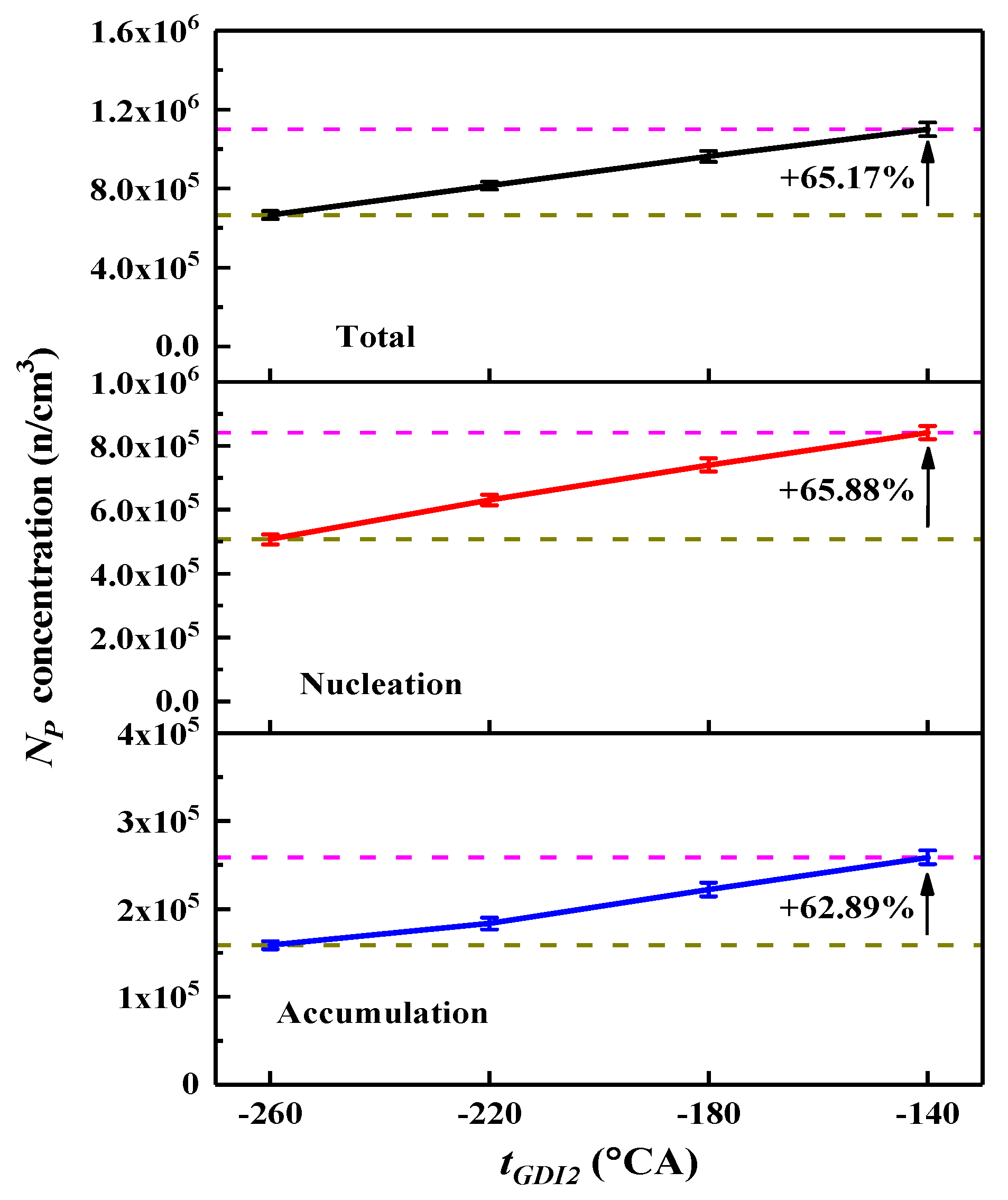
- (6)
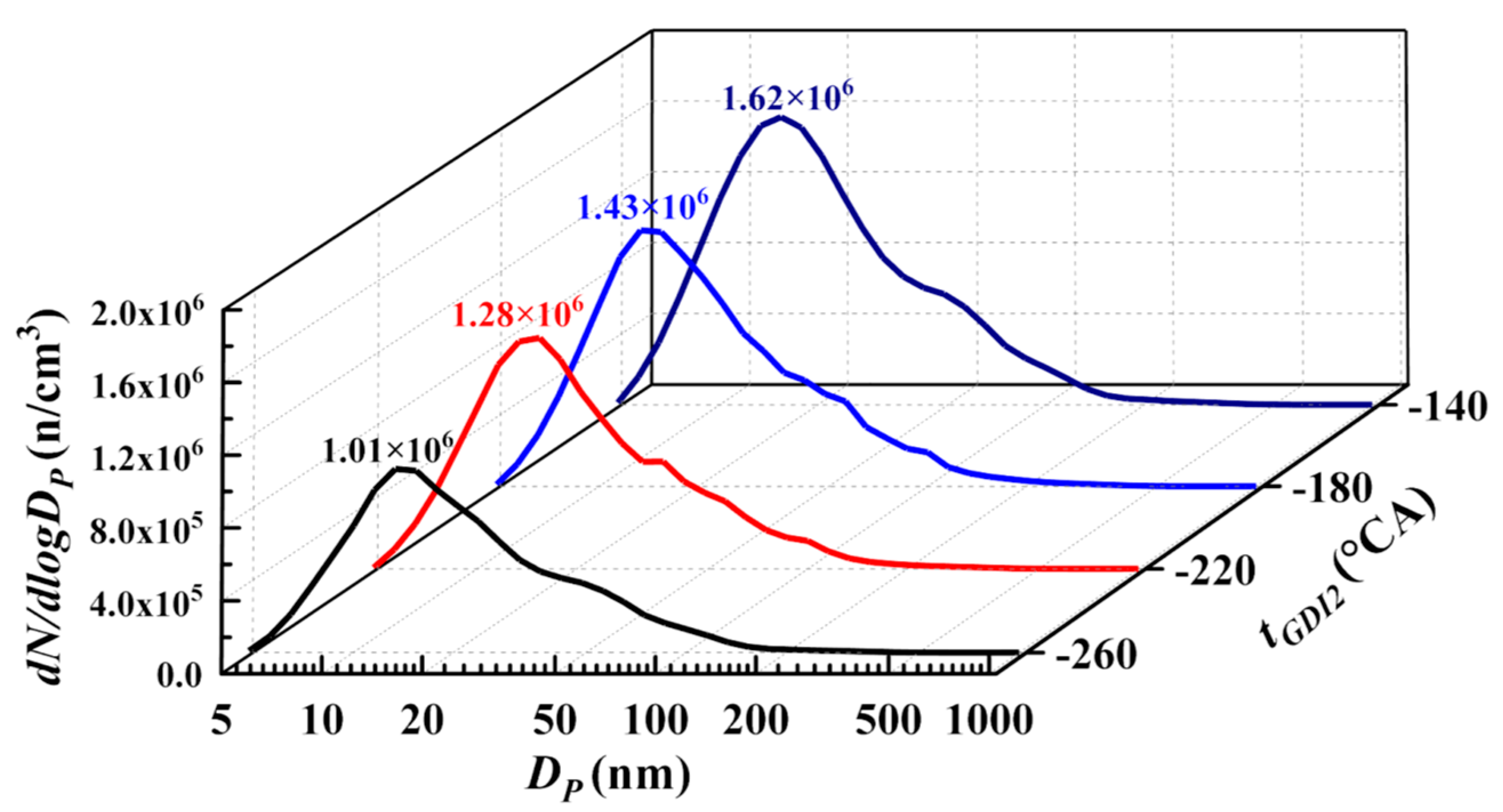
- With the delay in , the magnitude of the size distribution curve shows a growing tendency. concentrations of nucleation, accumulation, and total particulates present an increase of 65.17%, 65.88%, and 62.89%, respectively.
Author Contributions
Funding
Institutional Review Board Statement
Informed Consent Statement
Data Availability Statement
Conflicts of Interest
Nomenclature
| BMEP | Brake Mean Effective Pressure |
| CA | Crank Angle |
| CO | Carbon monoxide |
| DFSI | Dual-Fuel Spark Ignition |
| ECU | Electronic Control Unit |
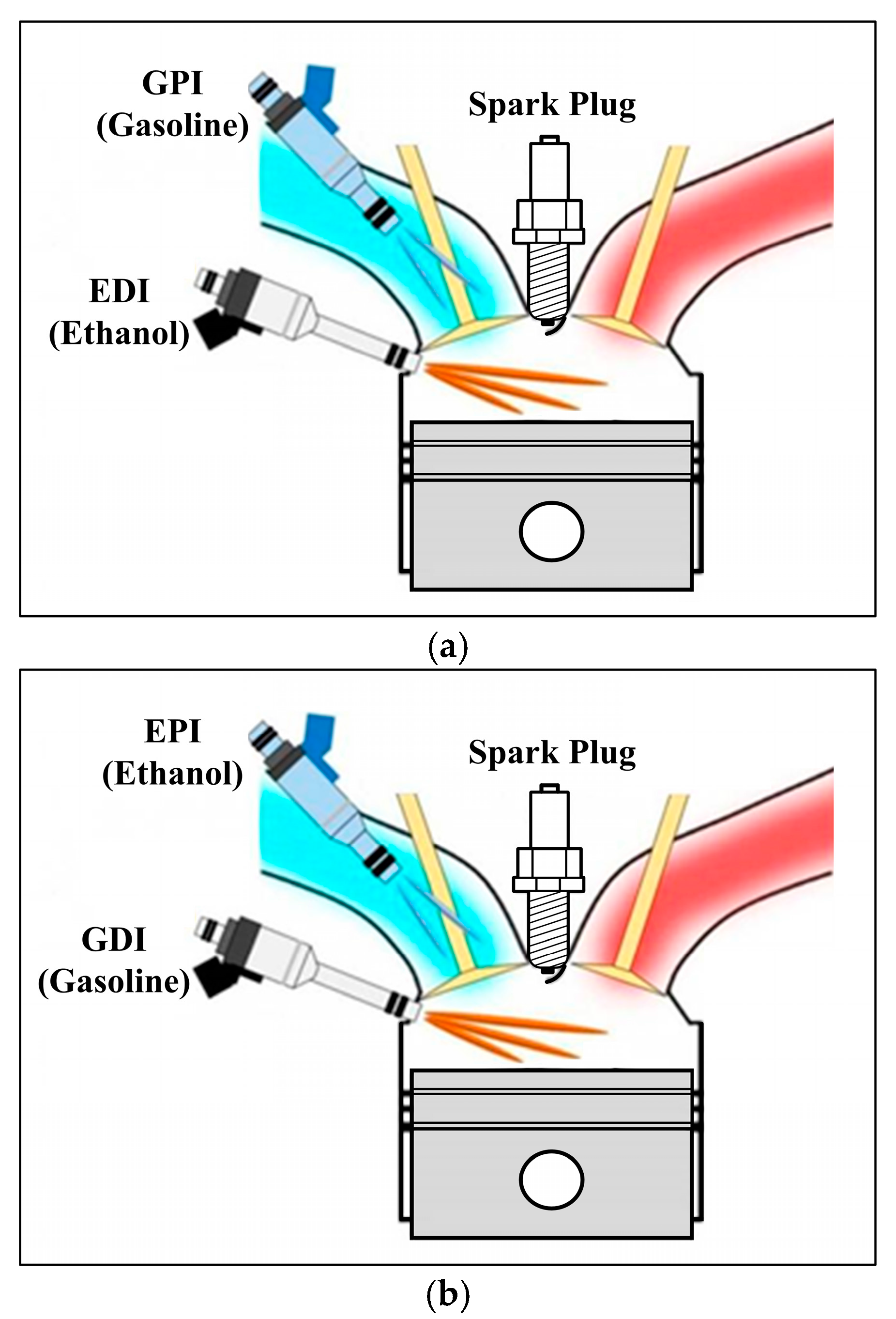
| EDI | Ethanol Direct Injection |
| EPI | Ethanol Port Injection |
| GDI | Gasoline Direct Injection |
| GPI | Gasoline Port Injection |
| HC | Hydrocarbon |
| ICE | Internal Combustion Engine |
| MBT | Maximum Brake Torque |
| NO | Nitric Oxide |
| WOT | Wide Open Throttle |
| rpm | revolutions per minute |
| particulate diameter | |
| particulate mass | |
| particulate number | |
| Gasoline Port Injection Pressure | |
| exhaust gas temperature | |
| maximum in-cylinder temperature | |
| injection timing of the second stage in the split GDI strategy | |
| ignition delay | |
| the CA where 10% of cumulative heat has been released |
References
- Pan, M.; Huang, R.; Liao, J.; Ouyang, T.; Zheng, Z.; Lv, D.; Huang, H. Effect of EGR dilution on combustion, performance and emission characteristics of a diesel engine fueled with n-pentanol and 2-ethylhexyl nitrate additive. Energy Convers. Manag. 2018, 176, 246–255. [Google Scholar] [CrossRef]
- Huang, Y.; Lee CK, C.; Yam, Y.S.; Mok, W.C.; Zhou, J.L.; Zhuang, Y.; Surawski, N.C.; Organ, B.; Chan, E.F.C. Rapid detection of high-emitting vehicles by on-road remote sensing technology improves urban air quality. Sci. Adv. 2022, 8, eabl7575. [Google Scholar] [CrossRef]
- Pfau, S.A.; La Rocca, A.; Haffner-Staton, E.; Fay, M.W.; Cairns, A. Linking operating conditions of a GDI engine to the nature and nanostructure of ultrafine soot particles. Combust. Flame 2022, 245, 112315. [Google Scholar] [CrossRef]
- Huang, H.; Chen, R.; Tao, S.; Wang, Y.; Zhang, L. Study of soot dynamic behavior and catalytic regeneration in diesel particulate filters. Chem. Eng. J. 2024, 489, 151498. [Google Scholar] [CrossRef]
- Li, L.; Guo, S.; Cai, H.; Wang, J.; Zhang, J.; Ni, Y. Can China’s BEV market sustain without government subsidies?: An explanation using cues utilization theory. J. Clean. Prod. 2020, 272, 122589. [Google Scholar] [CrossRef]
- İnci, M.; Büyük, M.; Demir, M.H.; ĺlbey, G. A review and research on fuel cell electric vehicles: Topologies, power electronic converters, energy management methods, technical challenges, marketing and future aspects. Renew. Sustain. Energy Rev. 2021, 137, 110648. [Google Scholar] [CrossRef]
- Chai, W.S.; Bao, Y.; Jin, P.; Tang, G.; Zhou, L. A review on ammonia, ammonia-hydrogen and ammonia-methane fuels. Renew. Sustain. Energy Rev. 2021, 147, 111254. [Google Scholar] [CrossRef]
- Gao, J.; Wang, X.; Song, P.; Tian, G.; Ma, C. Review of the backfire occurrences and control strategies for port hydrogen injection internal combustion engines. Fuel 2022, 307, 121553. [Google Scholar] [CrossRef]
- Duan, X.; Xu, L.; Xu, L.; Jiang, P.; Gan, T.; Liu, H.; Ye, S.; Sun, Z. Performance analysis and comparison of the spark ignition engine fuelled with industrial by-product hydrogen and gasoline. J. Clean. Prod. 2023, 424, 138899. [Google Scholar] [CrossRef]
- Zhuang, Y.; Zhu, G.; Gong, Z.; Wang, C.; Huang, Y. Experimental and numerical investigation of performance of an ethanol-gasoline dual-injection engine. Energy 2019, 186, 115835. [Google Scholar] [CrossRef]
- Zhao, Z.; Yu, X.; Huang, Y.; Shi, W.; Guo, Z.; Li, Z.; Du, Y.; Jin, Z.; Li, D.; Wang, T.; et al. Experimental study on combustion and emission of an SI engine with ethanol/gasoline combined injection and EGR. J. Clean. Prod. 2022, 331, 129903. [Google Scholar] [CrossRef]
- Li, X.; Li, D.; Liu, J.; Ajmal, T.; Aitouche, A.; Mobasheri, R.; Rybdylova, O.; Pei, Y.; Peng, Z. Exploring the potential benefits of Ethanol Direct Injection (EDI) timing and pressure on particulate emission characteristics in a Dual-Fuel Spark Ignition (DFSI) engine. J. Clean. Prod. 2022, 357, 131938. [Google Scholar] [CrossRef]
- Kim, N.; Cho, S.; Min, K. A study on the combustion and emission characteristics of an SI engine under full load conditions with ethanol port injection and gasoline direct injection. Fuel 2015, 158, 725–732. [Google Scholar] [CrossRef]
- Liu, H.; Wang, Z.; Long, Y.; Xiang, S.; Wang, J.; Fatouraie, M. Comparative study on alcohol–gasoline and gasoline–alcohol Dual-Fuel Spark Ignition (DFSI) combustion for engine particle number (PN) reduction. Fuel 2015, 159, 250–258. [Google Scholar] [CrossRef]
- Kang, R.; Zhou, L.; Hua, J.; Feng, D.; Wei, H.; Chen, R. Experimental investigation on combustion characteristics in dual-fuel dual-injection engine. Energy Convers. Manag. 2019, 181, 15–25. [Google Scholar] [CrossRef]
- Yu, X.; Guo, Z.; Sun, P.; Wang, S.; Li, A.; Yang, H.; Li, Z.; Liu, Z.; Li, J.; Shang, Z. Investigation of combustion and emissions of an SI engine with ethanol port injection and gasoline direct injection under lean burn conditions. Energy 2019, 189, 116231. [Google Scholar] [CrossRef]
- Wang, C.; Pei, Y.; Peng, Z.; Li, X. Insights into the effects of direct injection timing on the characteristics of deposited fuel film and Particulate Matter (PM) emissions from a Dual-Fuel Spark Ignition (DFSI) engine. Fuel Process. Technol. 2022, 238, 107515. [Google Scholar] [CrossRef]
- Lee, Z.; Park, S. Particulate and gaseous emissions from a direct-injection spark ignition engine fueled with bioethanol and gasoline blends at ultra-high injection pressure. Renew. Energy 2020, 149, 80–90. [Google Scholar] [CrossRef]
- Chang, F.; Luo, H.; Zhan, C.; Nishida, K.; Ogata, Y. Droplets velocity and diameter variations of wall impinging spray created by slicer. Fuel 2021, 299, 120894. [Google Scholar] [CrossRef]
- Ramalingam, S.; Babu, D.; Santhoshkumar, A.; Deepakkumar, R.; Ravikanth, D. Impact of exhaust gas recirculation and split injection strategy combustion behavior on premixed charge compression ignition engine fuelled with moringa oleifera methyl ester. Fuel 2022, 319, 123702. [Google Scholar] [CrossRef]
- Kumar, T.S.; Ashok, B.; Kumar, M.S.; Vignesh, R.; Saiteja, P.; Hire, K.R.B.; Tote, M.H.; Pandey, R.; Jadhav, A.; Gupta, A.; et al. Biofuel powered engine characteristics improvement through split injection parameter multivariate optimization with titanium based nano-particle additives. Fuel 2022, 322, 124178. [Google Scholar] [CrossRef]
- Li, X.; Pei, Y.; Ajmal, T.; Rana, K.-J.; Aitouche, A.; Mobasheri, R.; Peng, Z. Numerical investigation on implementing Oxy-Fuel Combustion (OFC) in an ethanol-gasoline Dual-Fuel Spark Ignition (DFSI) engine. Fuel 2021, 302, 121162. [Google Scholar] [CrossRef]
- Liu, H.; Li, Z.; Xu, H.; Ma, X.; Shuai, S. Nucleation mode particle evolution in a gasoline direct injection engine with/without a three-way catalyst converter. Appl. Energy 2020, 259, 114211. [Google Scholar] [CrossRef]
- Holman, J.P. Experimental Methods for Engineers, 8th ed.; McGraw-Hill: New York, NY, USA, 2021. [Google Scholar]
- Chen, L.; Liang, Z.; Zhang, X.; Shuai, S. Characterizing particulate matter emissions from GDI and PFI vehicles under transient and cold start conditions. Fuel 2017, 189, 131–140. [Google Scholar] [CrossRef]
- Li, X.; Zhang, X.; Ni, P.; Weerasinghe, R.; Pei, Y.; Peng, Z. Insights into the spray impingement process from a gasoline direct injection fuel system fuelled with gasoline and ethanol. J. Energy Inst. 2023, 110, 101331. [Google Scholar] [CrossRef]
- Richter, H.; Howard, J.B. Formation of polycyclic aromatic hydrocarbons and their growth to soot—A review of chemical reaction pathways. Prog. Energy Combust. Sci. 2000, 26, 565–608. [Google Scholar] [CrossRef]
- Jin, H.; Yuan, W.; Li, W.; Yang, J.; Zhou, Z.; Zhao, L.; Li, Y.; Qi, F. Combustion chemistry of aromatic hydrocarbons. Prog. Energy Combust. Sci. 2023, 96, 101076. [Google Scholar] [CrossRef]


| Items | Content |
|---|---|
| Engine type | 4-cylinder, 4-stroke |
| Bore × Stroke (mm) | 82.5 × 92 |
| Displacement (L) | 2.0 |
| Injection mode | EPI plus GDI |
| Intake mode | Turbocharged |
| Compression ratio | 9.6:1 |
| Rated speed (rpm) | 5500 |
| Rated power (kW) | 160 |
| Maximum torque (N·m) | 320 |
| Fuel Type | Ethanol | Gasoline |
|---|---|---|
| Chemical formula | C2H5OH | C5-C12 |
| Relative molecular mass | 46 | 95–120 |
| Gravimetric oxygen content (%) | 34.78 | <1 |
| Research octane number | 107 | 95 |
| Density (293 K) (kg/L) | 0.789 | 0.73 |
| Dynamic viscosity (293 K) (mPa·s) | 1.2 | 0.52 |
| Kinematic viscosity (293 K) (mm2/s) | 1.52 | 0.71 |
| Surface tension coefficient (293 K) (mN/m) | 21.97 | 22 |
| Boiling range (K) | 351 | 303–473 |
| Lower heating value (kJ/kg) | 26,900 | 44,300 |
| Latent heat of vaporisation (kJ/kg) | 840 | 370 |
| Laminar flame speed (293 K) (m/s) | 0.5 | 0.33 |
| Stoichiometric air–fuel ratio | 8.95 | 14.7 |
| Measured Parameters | Uncertainty (%) |
|---|---|
| Engine speed | ±0.1 |
| BMEP | ±0.1 |
| Fuel consumption rate | ±0.2 |
| Pressure | ±0.1 |
| Crank angle | ±0.1 |
| Lambda | ±0.2 |
| Coolant temperature | ±0.4 |
| Intercooler output temperature | ±0.4 |
| Particulate emissions | ±1.5 |
Disclaimer/Publisher’s Note: The statements, opinions and data contained in all publications are solely those of the individual author(s) and contributor(s) and not of MDPI and/or the editor(s). MDPI and/or the editor(s) disclaim responsibility for any injury to people or property resulting from any ideas, methods, instructions or products referred to in the content. |
© 2024 by the authors. Licensee MDPI, Basel, Switzerland. This article is an open access article distributed under the terms and conditions of the Creative Commons Attribution (CC BY) license (https://creativecommons.org/licenses/by/4.0/).
Share and Cite
Li, X.; Liu, S.; Li, W.; Pei, Y.; Zhang, X.; Ni, P.; Peng, Z.; Wang, C. Optimising the Particulate Emission Characteristics of a Dual-Fuel Spark Ignition Engine by Changing the Gasoline Direct Injection Strategy. Sustainability 2024, 16, 8713. https://doi.org/10.3390/su16198713
Li X, Liu S, Li W, Pei Y, Zhang X, Ni P, Peng Z, Wang C. Optimising the Particulate Emission Characteristics of a Dual-Fuel Spark Ignition Engine by Changing the Gasoline Direct Injection Strategy. Sustainability. 2024; 16(19):8713. https://doi.org/10.3390/su16198713
Chicago/Turabian StyleLi, Xiang, Siyue Liu, Wanzhong Li, Yiqiang Pei, Xuewen Zhang, Peiyong Ni, Zhijun Peng, and Chenxi Wang. 2024. "Optimising the Particulate Emission Characteristics of a Dual-Fuel Spark Ignition Engine by Changing the Gasoline Direct Injection Strategy" Sustainability 16, no. 19: 8713. https://doi.org/10.3390/su16198713