

Comparative Study of Life-Cycle Environmental and Cost Performance of Aluminium Alloy–Concrete Composite Columns


Abstract
:1. Introduction
Research Significance
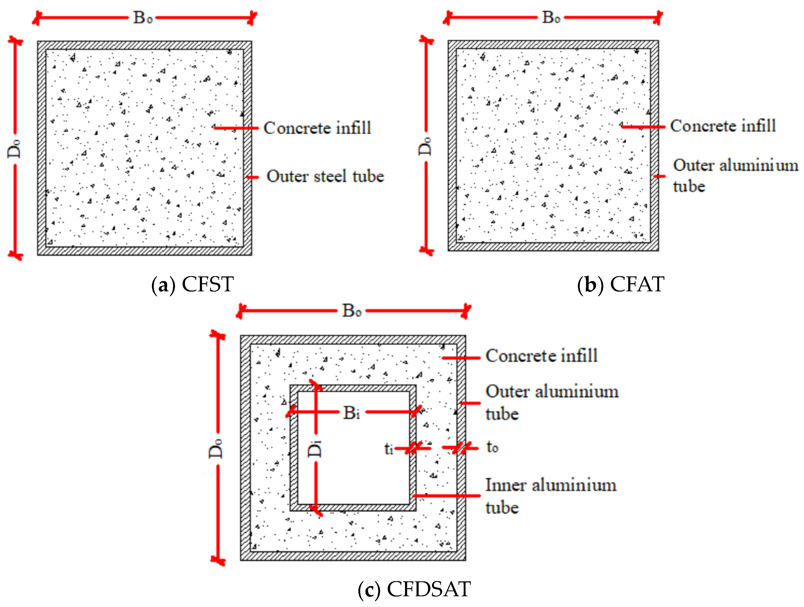
2. Investigated Composite Columns
2.1. Material Properties
2.2. Structural Design and Dimensions of Composite Columns
3. Comparison of Self-Weight of Columns
4. Life-Cycle Model
4.1. Goal and Scope Definition
4.2. Life-Cycle Stages
5. Life-Cycle Assessment (LCA)
5.1. LCA Inventory Data
5.2. LCA Results and Discussions
6. Life-Cycle Cost Analysis (LCCA)
6.1. LCCA Model and Data
6.2. LCCA Results and Discussions
7. Sensitivity Analysis
7.1. Renewable Energy Use
7.2. Maintenance-to-Initial Ratio
7.3. Simultaneous Variation in Renewable Energy Use and Maintenance-to-Initial Ratio
7.4. Discount Rate
8. Conclusions
- It was found that the self-weight of the studied CFAT and CFDSAT columns is around 17% and 47% lower than that of the CFST column. Therefore, it can be concluded that the self-weight of CFST column can be reduced by replacing steel with aluminium alloy and it becomes significantly lighter when the double-skin form is applied using aluminium alloy hollow sections.
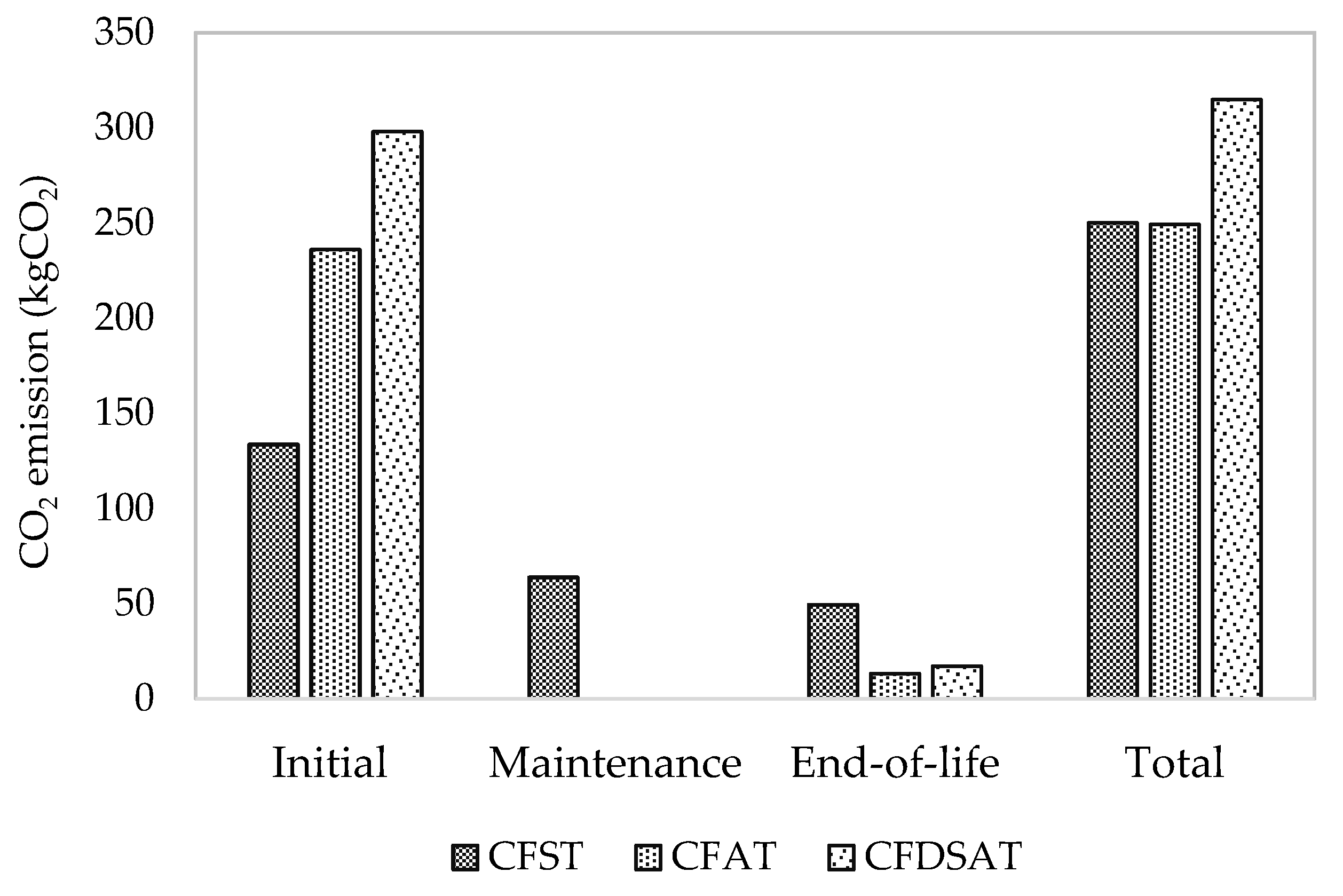
- It was observed from the LCA that the carbon footprint of CFST and CFAT is almost the same, which is 21% lower than that of the CFDSAT columns because of the high aluminium usage in the latter. Therefore, it can be concluded that the high embodied carbon in CFAT columns can be offset by fewer maintenance needs, owing to its superior corrosion resistance compared with CFST. However, excessive use of aluminium such as in the CFDSAT composite column will result in an increase in carbon emissions.
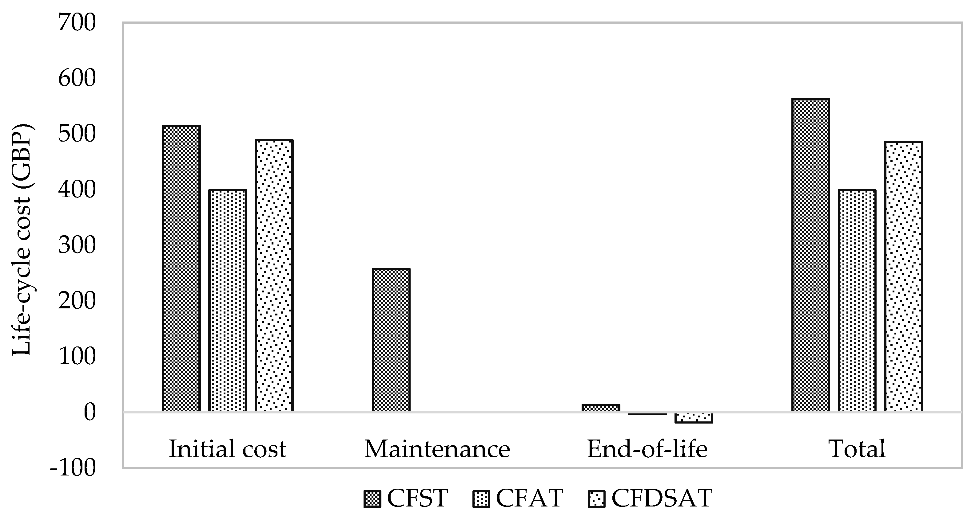
- The LCCA results show that the total life-cycle cost of CFAT and CFDSAT columns is around 29% and 14% lower, respectively, than that of the CFST column, largely due to assuming no expense related to the maintenance because of the excellent corrosion resistance of aluminium. It suggests that the CFAT column is the most cost-effective design solution compared to the other two composite columns.
- From the sensitivity analysis, it was found that by using decarbonised electricity in the production of steel and aluminium, the total environmental impacts of the CFST, CFAT and CFDSAT columns can be reduced significantly. A reduction of 31%, 42% and 45% for the CFST, CFAT and CFDSAT columns, respectively, can be achieved when a 50% CO2 reduction in the production of steel and aluminium is considered. A higher reduction in carbon emissions by CFAT and CFDSAT columns is observed at the maintenance and end-of-life stages compared to the CFST column.
- With the increase in the maintenance-to-initial ratio, the CO2 emissions of CFAT and CFDSAT increase noticeably compared to the CFST column, whereas the CFST column remains the costliest alternative in all maintenance-to-initial ratios. Future studies could include a sensitivity analysis of the corrosion resistance of aluminium columns as well as of the residual value of scrap metals when data become available.
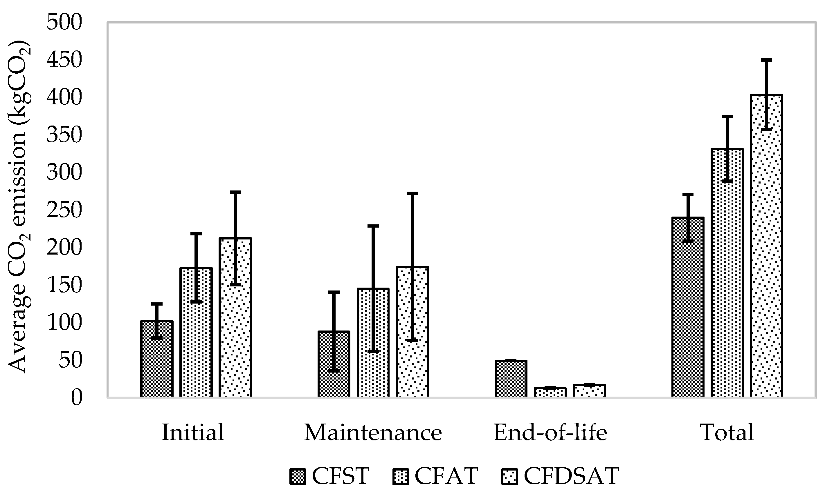
- From a global sensitivity analysis, it was observed that the average life-cycle CO2 emission of CFST column is 38.2% and 68.3% lower than that of CFAT and CFDSAT due to low environmental impact at the initial and maintenance stages of steel.
- Finally, the life-cycle cost of CFAT and CFDSAT columns is less sensitive to the variation in the discount rate, which is mainly due to the durability of aluminium assumed in the analysis period, i.e., 50 years.
9. Future Research
Author Contributions
Funding
Institutional Review Board Statement
Informed Consent Statement
Data Availability Statement
Conflicts of Interest
References
- Morino, S.; Uchikoshi, M.; Yamaguchi, I. Concrete-filled steel tube column system-its advantages. Int. J. Steel Struct. 2001, 1, 33–44. [Google Scholar]
- Morino, S.; Tsuda, K. Design and construction of concrete-filled steel tube column system in Japan. Earthq. Eng. Eng. Seismol. 2002, 4, 51–73. [Google Scholar]
- Lam, D.; Wong, K. Axial capacity of concrete filled stainless steel columns. In Proceedings of the Structures Congress, New York, NY, USA, 20–24 April 2005. [Google Scholar] [CrossRef]
- Starossek, U.; Falah, N.; Lohning, T. Numerical analyses of the force transfer in concrete-filled steel tube columns. Struct. Eng. Mech. 2010, 35, 241–256. [Google Scholar] [CrossRef]
- McLennan, J.F. The Philosophy of Sustainable Design: The Future of Architecture; Ecotone Publishing Company: Washington, DC, USA, 2004; p. 4. [Google Scholar]
- Hastak, M.; Halpin, D.W. Assessment of life-cycle benefit-cost of composites in construction. J. Compos. Constr. 2000, 4, 103–111. [Google Scholar] [CrossRef]
- Rossi, B.; Lukic, I.; Iqbal, N.; Du, G.L.; Cregg, D.; Borg, R.P.; Haller, P. Life cycle impacts assessment of steel, composite, concrete and wooden columns. In Proceedings of the International Conference on Sustainability of Constructions—Towards a Better Built Environment, Innsbruck, Austria, 3–5 February 2011. [Google Scholar]
- Hou, C.C.; Han, L.H. Life-cycle performance of deteriorated concrete-filled steel tubular (CFST) structures subject to lateral impact. Thin-Walled Struct. 2018, 132, 362–374. [Google Scholar] [CrossRef]
- Duarte, A.P.C.; Silvestre, N.; Brito, J.D.; Júlio, E.; Silvestre, J.D. On the sustainability of rubberized concrete filled square steel tubular columns. J. Clean. Prod. 2018, 170, 510–521. [Google Scholar] [CrossRef]
- Zhao, M.; Dong, Y.; Guo, H. Comparative life cycle assessment of composite structures incorporating uncertainty and global sensitivity analysis. Eng. Struct. 2021, 242, 112394. [Google Scholar] [CrossRef]
- Zhou, F.; Young, B. Tests of concrete-filled aluminum stub columns. Thin-Walled Struct. 2008, 46, 573–583. [Google Scholar] [CrossRef]
- Zhou, F.; Young, B. Concrete-filled double-skin aluminum circular hollow section stub columns. Thin-Walled Struct. 2018, 133, 141–152. [Google Scholar] [CrossRef]
- Zhou, F.; Young, B. Compressive strengths of concrete-filled double-skin (circular hollow section outer and square hollow section inner) aluminium tubular sections. Advances Struct. Eng. 2019, 22, 1–17. [Google Scholar] [CrossRef]
- Wang, F.; Zhao, H.; Han, L. Analytical behavior of concrete-filled aluminum tubular stub columns under axial compression. Thin-Walled Struct. 2019, 140, 21–30. [Google Scholar] [CrossRef]
- Feng, R.; Chen, Y.; Gong, W. Flexural behaviour of concrete-filled aluminium alloy thin-walled SHS and RHS tubes. Eng Struct. 2017, 137, 33–49. [Google Scholar] [CrossRef]
- Chen, Y.; Feng, R.; Gong, W. Flexural behavior of concrete-filled aluminum alloy circular hollow section tubes. Constr. Build. Mater. 2018, 165, 295–319. [Google Scholar] [CrossRef]
- Ali, S.B.; Kamaris, G.S.; Gkantou, M.; Kansara, K.D. Concrete-filled and bare 6082-T6 aluminium alloy tubes under in-plane bending: Experiments, finite element analysis and design recommendations. Thin-Walled Struct. 2022, 172, 108907. [Google Scholar] [CrossRef]
- Ali, S.B.; Kamaris, G.S.; Gkantou, M. Flexural behaviour of concrete-filled double skin aluminium alloy tubes. Eng. Struct. 2022, 272, 114972. [Google Scholar] [CrossRef]
- Georgantzia, E.; Ali, S.B.; Gkantou, M.; Kamaris, G.S.; Kansara, K.D.; Atherton, W. Flexural buckling performance of concrete-filled aluminium alloy tubular columns. Eng. Struct. 2020, 242, 112546. [Google Scholar] [CrossRef]
- Ali, S.B.; Kamaris, G.S.; Gkantou, M. Flexural buckling behaviour of concrete-filled double skin aluminium alloy columns. Eng. Struct. 2023, 275, 115316. [Google Scholar] [CrossRef]
- EN 1990:2002; Eurocode: Basis of Structural Design. European Committee for Standardisation (CEN): Brussels, Belgium, 2002.
- EN 1991-1-1:2002; Eurocode 1: Actions on Structures—Part 1-1: General Actions—Densities, Self-Weight, Imposed Loads for Buildings. European Committee for Standardisation (CEN): Brussels, Belgium, 2002.
- Tao, Z.; Han, L.H.; Zhao, X.L. Behaviour of concrete-filled double skin (CHS inner and CHS outer) steel tubular stub columns and beam-columns. J. Compos. Constr. 2004, 60, 1129–1158. [Google Scholar] [CrossRef]
- EN 1994-1-1:2004; Eurocode 4: Design of Composite Steel and Concrete Structures. Part 1-1. General Rules and Rules for Buildings. European Committee for Standardisation (CEN): Brussels, Belgium, 2004.
- EN 1999-1-1:2007; Eurocode 9: Design of Aluminium Structures. Part 1-1. General Structural Rules—General Structural Rules and Rules for Buildings. European Committee for Standardisation (CEN): Brussels, Belgium, 2007.
- Wang, Y.; Cao, M.M.; Sun, H. Time-dependent reliability analysis of circular CFST stub columns under environment corrosion. Pac. Sci. Rev. 2014, 16, 201–206. [Google Scholar] [CrossRef]
- Gardner, L.; Cruise, R.B.; Sok, C.P.; Krishnan, K.; Ministro, J. Life cycle costing of metallic structures. Proc. Inst. Civ. Eng. Eng. Sustain. 2007, 160, 167–177. [Google Scholar] [CrossRef]
- Aslani, F.; Ma, G.; Wan, D.L.Y.; Muselin, G. Development of high-performance selfcompacting concrete using waste recycled concrete aggregates and rubber granules. J. Clean. Prod. 2018, 182, 553–566. [Google Scholar] [CrossRef]
- Silva, R.V.; De Brito, J.; Dhir, R.K. Availability and processing of recycled aggregates within the construction and demolition supply chain: A review. J. Clean. Prod. 2017, 143, 598–614. [Google Scholar] [CrossRef]
- Müller, H.S.; Breiner, R.; Moffatt, J.S.; Haist, M. Design and properties of sustainable concrete. Procedia Eng. 2014, 95, 290–304. [Google Scholar] [CrossRef]
- Worldsteel Association. Sustainability Performance of the Steel Industry 2004–2022; Sustainability Indicators 2023 Report; Worldsteel Association: Brussels, Belgium, 2023. [Google Scholar]
- European Aluminium. Environmental Profile Report: Life-Cycle Inventory Data for Aluminium Production and Transformation Processes in Europe; European Aluminium: Brussels, Belgium, 2018. [Google Scholar]
- Xu, K.; Kang, H.; Wang, W.; Jiang, P.; Li, N. Carbon emission estimation of assembled composite concrete beams during construction. Energies 2021, 14, 1810. [Google Scholar] [CrossRef]
- Ceb-Fip. Ceb-Fip Model Code 1990; Thomas Telford Ltd.: London, UK, 1993. [Google Scholar]
- Cho, S.H.; Chae, C.U. A Study on Life Cycle CO2 Emissions of Low-Carbon Building in South Korea. Sustainability 2016, 8, 579. [Google Scholar] [CrossRef]
- European Aluminium. Environmental Profile Report: For the Aluminium Refining Industry; European Aluminium: Brussels, Belgium, 2021. [Google Scholar]
- Bureau of International Recycling, Ferrous Metals: Extract Bir Annual Report 2022. Available online: https://www.bir.org/the-industry/ferrous-metals (accessed on 11 December 2023).
- 8billiontrees, Carbon Footprint of Steel per kg & lb (Calculator & Full List of Steel Items). Available online: https://8billiontrees.com/carbon-offsets-credits/carbon-footprint-of-steel (accessed on 12 December 2023).
- Blue Circle Multipurpose Cement, 25 kg Bag. Available online: https://www.diy.com/departments/blue-circle-multipurpose-cement-25kg-bag/35715_BQ.prd (accessed on 11 December 2023).
- Resapol, Stone 10 mm, 25 kg. Available online: https://www.resapol.com/product/limestone-10mm-25kg/ (accessed on 11 December 2023).
- Wickes, Building Sand. Available online: https://www.wickes.co.uk/Tarmac-Building-Sand---Jumbo-Bag/p/131889 (accessed on 11 December 2023).
- Metalsupermarkets, Mild Steel. Available online: https://www.metalsupermarkets.co.uk/metals/mild-steel/ (accessed on 11 December 2023).
- Simmal, Aluminium Tube. Available online: https://www.simmal.com/product-category/aluminium-tube/ (accessed on 11 December 2023).
- Chan, T.K.; Aibinu, A.A. A comparison of construction cost and technology choice. In Proceedings of the Management of Construction: Research to Practice Conference, Montreal, QC, Canada, 26–29 June 2012. [Google Scholar]
- Linear Recruitment, Highest Paying Construction Jobs in the UK. Available online: https://www.linearrecruitment.co.uk/news/highest-paying-construction-jobs-uk (accessed on 11 December 2023).
- Scrapmetalpricesuk, Scrap Metal Prices UK. Available online: http://www.scrapmetalpricesuk.co.uk (accessed on 11 December 2023).
- Younis, A.; Ebead, U.; Judd, S. Life cycle cost analysis of structural concrete using seawater, recycled concrete aggregate, and GFRP reinforcement. Constr. Build. Mater. 2018, 175, 152–160. [Google Scholar] [CrossRef]
- GOV.UK, DHSC Group Accounting Manual 2022 to 2023: Additional Guidance, Version 3. Available online: https://www.gov.uk/government/publications/dhsc-group-accounting-manual-2022-to-2023/dhsc-group-accounting-manual-2022-to-2023-additional-guidance-version-1 (accessed on 11 December 2023).
- International Aluminium Institute. Aluminium, Shaping a Better Tomorrow. Available online: https://international-aluminium.org/new-test-article/ (accessed on 11 December 2023).
- Ledari, M.B.; Khajehpour, H.; Akbarnavasi, H.; Edalati, S. Greening steel industry by hydrogen: Lessons learned for the developing world. Int. J. Hydrogen Energy 2023, 48, 36623–36649. [Google Scholar] [CrossRef]


| Column | Do (mm) | Bo (mm) | to (mm) | Di (mm) | Bi (mm) | ti (mm) | L (mm) |
|---|---|---|---|---|---|---|---|
| CFST | 150 | 150 | 4 | - | - | - | 3000 |
| CFAT | 150 | 150 | 6.75 | - | - | - | 3000 |
| CFDSAT | 150 | 150 | 6.75 | 100 | 100 | 3.61 | 3000 |
| Column | Component | Reference | Material Properties | |||
|---|---|---|---|---|---|---|
| E (GPa) | f0.1 (MPa) | f0.2 (MPa) | fc (MPa) | |||
| CFST | Steel tube | [23] | 200 | 276 | Not available | - |
| Concrete | [19] | 32,837 | - | - | 30 | |
| CFAT | Aluminium tube | [19] | 69 | 276 | 315 | - |
| Concrete | [19] | 32,837 | - | - | 30 | |
| CFDSAT | Outer aluminium tube | [19] | 69 | 276 | 315 | - |
| Inner aluminium tube | [19] | 69 | 276 | 315 | - | |
| Concrete | [19] | 32,837 | - | - | 30 | |
| Material | Density (kg/m3) | CFST | CFAT | CFDSAT | |||
|---|---|---|---|---|---|---|---|
| Volume (m3) | Mass (kg) | Volume (m3) | Mass (kg) | Volume (m3) | Mass (kg) | ||
| Concrete | 2400 | 0.06 | 145.18 | 0.06 | 134.13 | 0.026 | 62.13 |
| Steel tube | 7850 | 0.01 | 55.01 | - | - | - | - |
| Outer aluminium tube | 2700 | - | - | 0.01 | 31.35 | 0.012 | 31.35 |
| Inner aluminium tube | 2700 | - | - | - | - | 0.004 | 11.26 |
| Sum (kg) | 200.19 | 165.48 | 104.75 | ||||
| Reduction (%) | 0% | −17% | −47% | ||||
| Column | Life-Cycle Stage | Consumed Material | Amount | Unit | GWP Coefficient | Unit | Reference | GWP (kgCO2) |
|---|---|---|---|---|---|---|---|---|
| CFST | Production | Cement | 26.62 | kg | 0.951 | kgCO2/kg | [30] | 25.31 |
| Fine aggregate | 38.71 | kg | 0.001 | kgCO2/kg | [30] | 0.04 | ||
| Coarse aggregate | 65.63 | kg | 0.001 | kgCO2/kg | [30] | 0.07 | ||
| Steel tube | 55.01 | kg | 1.910 | kgCO2/kg | [31] | 105.07 | ||
| Sum | 130.50 | |||||||
| Transportation | Materials for concrete (5.7 km) | 0.75 | t.km | 0.166 | kgCO2/t.km | [33] | 0.12 | |
| Steel tube (32.9 km) | 1.81 | t.km | 0.166 | kgCO2/t.km | [33] | 0.30 | ||
| Sum | 0.43 | |||||||
| Construction | Concrete | 145.18 | kg | 0.016 | kgCO2/kg | [34] | 2.32 | |
| Steel tube | 55.01 | kg | 0.008 | kgCO2/kg | [10] | 0.44 | ||
| Sum | 2.76 | |||||||
| Maintenance | (Maintenance-to-initial ratio = 0.1) | [10] | 66.84 | |||||
| End-of-life | Concrete-landfill | 145.18 | kg | 0.007 | kgCO2/kg | [35] | 1.02 | |
| Steel tube (100% recycled) | 55.01 | kg | 0.880 | kgCO2/kg | [31] | 48.41 | ||
| Sum | 49.43 | |||||||
| Total | 249.96 | |||||||
| CFAT | Production | Cement | 24.59 | kg | 0.951 | kgCO2/kg | [30] | 23.39 |
| Fine aggregate | 35.77 | kg | 0.001 | kgCO2/kg | [30] | 0.04 | ||
| Coarse aggregate | 60.65 | kg | 0.001 | kgCO2/kg | [30] | 0.06 | ||
| Aluminium tube | 31.33 | kg | 6.70 | kgCO2/kg | [32] | 209.9 | ||
| Sum | 233.39 | |||||||
| Transportation | Materials concrete (5.7 km) | 0.69 | t.km | 0.166 | kgCO2/t.km | [33] | 0.11 | |
| Aluminium tube (32.9 km) | 1.03 | t.km | 0.166 | kgCO2/t.km | [33] | 0.17 | ||
| Sum | 0.29 | |||||||
| Construction | Concrete | 134.15 | kg | 0.016 | kgCO2/kg | [34] | 2.15 | |
| Aluminium tube | 31.33 | kg | 0.008 | kgCO2/kg | 0.25 | |||
| Sum | 2.40 | |||||||
| Maintenance | (Maintenance-to-initial ratio = 0) | 0.00 | ||||||
| End-of-life | Concrete-landfill | 134.13 | kg | 0.007 | kgCO2/kg | [35] | 0.94 | |
| Aluminium tube (100% recycled) | 31.33 | kg | 0.390 | kgCO2/kg | [36] | 12.22 | ||
| Sum | 13.16 | |||||||
| Total | 249.23 | |||||||
| CFDSAT | Production | Cement | 11.39 | kg | 0.951 | kgCO2/kg | [30] | 10.83 |
| Fine aggregate | 16.57 | kg | 0.001 | kgCO2/kg | [30] | 0.02 | ||
| Coarse aggregate | 28.10 | kg | 0.001 | kgCO2/kg | [30] | 0.03 | ||
| Aluminium outer tube | 31.33 | kg | 2.68 | kgCO2/kg | [32] | 209.9 | ||
| Aluminium inner tube | 11.26 | kg | 2.68 | kgCO2/kg | [32] | 75.47 | ||
| Sum | 296.25 | |||||||
| Transportation | Materials concrete (5.7 km) | 0.32 | t.km | 0.166 | kgCO2/t.km | [33] | 0.05 | |
| Aluminium tube (32.9 km) | 1.40 | t.km | 0.166 | kgCO2/t.km | [33] | 0.23 | ||
| Sum | 0.29 | |||||||
| Construction | Concrete | 62.13 | kg | 0.016 | kgCO2/kg | [34] | 0.99 | |
| Aluminium tube | 42.59 | kg | 0.008 | kgCO2/kg | 0.34 | |||
| Sum | 1.33 | |||||||
| Maintenance | (Maintenance-to-initial ratio = 0) | 0.00 | ||||||
| End-of-life | Concrete-landfill | 62.13 | kg | 0.007 | kgCO2/kg | [35] | 0.43 | |
| Aluminium tube (100% recycled) | 42.59 | kg | 0.390 | kgCO2/kg | [36] | 16.61 | ||
| Sum | 17.05 | |||||||
| Total | 314.92 | |||||||
| Column | Life-Cycle Stage | Consumed Material | Amount/Hour | Unit | Unit Cost | Unit | Reference | Cost (GBP) |
|---|---|---|---|---|---|---|---|---|
| CFST | Production | Cement | 26.62 | kg | 0.30 | GBP/kg | [39] | 7.98 |
| Fine aggregate | 38.71 | kg | 0.59 | GBP/kg | [41] | 22.84 | ||
| Coarse aggregate | 65.63 | kg | 0.07 | GBP/kg | [40] | 4.59 | ||
| Steel tube | 55.01 | kg | 6.95 | GBP/kg | [42] | 382.34 | ||
| Sum | 417.76 | |||||||
| Transportation | Materials for concrete (5.7 km) | 30.00 | ||||||
| Steel tube (32.9 km) | 21.50 | |||||||
| Sum | 51.50 | |||||||
| Construction | Concrete | 1.00 | h | 12.88 | GBP/h | [45] | 12.88 | |
| Steel tube | 2.50 | h | 12.88 | GBP/h | [45] | 32.20 | ||
| Sum | 45.08 | |||||||
| Maintenance | (Maintenance-to-initial ratio = 0.1) | [10] | 257.17 | |||||
| End-of-life | Concrete—demolition | 0.06 | m3 | 98.00 | GBP/m3 | [10] | 5.93 | |
| Concrete—landfill | 145.18 | kg | 0.07 | GBP/kg | [10] | 10.31 | ||
| Steel tube—100% recycled | 55.01 | kg | 0.06 | GBP/kg | [46] | −3.30 | ||
| Sum | 12.94 | |||||||
| Total | Interest rate | 3.51 | % | [10] | 562.47 | |||
| CFAT | Production | Cement | 24.59 | kg | 0.30 | GBP/kg | [39] | 7.38 |
| Fine aggregate | 35.77 | kg | 0.59 | GBP/kg | [41] | 21.10 | ||
| Coarse aggregate | 60.65 | kg | 0.07 | GBP/kg | [40] | 4.25 | ||
| Aluminium tube | 31.33 | kg | 8.62 | GBP/kg | [43] | 270.05 | ||
| Sum | 302.78 | |||||||
| Transportation | Materials concrete (5.7 km) | 30.00 | ||||||
| Aluminium tube (32.9 km) | 21.50 | |||||||
| Sum | 51.50 | |||||||
| Construction | Concrete | 1.00 | h | 12.88 | GBP/h | [45] | 12.88 | |
| Aluminium tube | 2.50 | h | 12.88 | GBP/h | [45] | 32.20 | ||
| Sum | 45.08 | |||||||
| Maintenance | (Maintenance-to-initial ratio = 0) | 0.00 | ||||||
| End-of-life | Concrete—demolition | 0.06 | m3 | 98.00 | GBP/m3 | [10] | 5.48 | |
| Concrete—landfill | 134.15 | kg | 0.07 | GBP/kg | [10] | 9.52 | ||
| Aluminium tube—100% recycled | 31.33 | kg | 0.60 | GBP/kg | [46] | −18.80 | ||
| Sum | −3.80 | |||||||
| Total | Interest rate | 3.51 | % | [10] | 398.68 | |||
| CFDSAT | Production | Cement | 11.39 | kg | 0.30 | GBP/kg | [39] | 3.42 |
| Fine aggregate | 16.57 | kg | 0.59 | GBP/kg | [41] | 9.78 | ||
| Coarse aggregate | 28.10 | kg | 0.07 | GBP/kg | [40] | 1.97 | ||
| Aluminium outer tube | 31.33 | kg | 8.62 | GBP/kg | [43] | 270.05 | ||
| Aluminium inner tube | 11.26 | kg | 9.51 | GBP/kg | [43] | 107.12 | ||
| Sum | 392.33 | |||||||
| Transportation | Materials concrete (5.7 km) | 30.00 | ||||||
| Aluminium tube (32.9 km) | 21.50 | |||||||
| Sum | 51.50 | |||||||
| Construction | Concrete | 1.00 | h | 12.88 | GBP/h | [45] | 12.88 | |
| Aluminium tube | 2.50 | h | 12.88 | GBP/h | [45] | 32.20 | ||
| Sum | 45.08 | |||||||
| Maintenance | (Maintenance-to-initial ratio = 0) | 0.00 | ||||||
| End-of-life | Concrete—demolition | 0.03 | m3 | 98.00 | GBP/m3 | [10] | 2.54 | |
| Concrete—landfill | 62.15 | kg | 0.07 | GBP/kg | [10] | 4.41 | ||
| Aluminium tube—100% recycled | 42.59 | kg | 0.60 | GBP/kg | [46] | −25.56 | ||
| Sum | −18.61 | |||||||
| Total | Interest rate | 3.51 | % | [10] | 485.60 | |||
Disclaimer/Publisher’s Note: The statements, opinions and data contained in all publications are solely those of the individual author(s) and contributor(s) and not of MDPI and/or the editor(s). MDPI and/or the editor(s) disclaim responsibility for any injury to people or property resulting from any ideas, methods, instructions or products referred to in the content. |
© 2024 by the authors. Licensee MDPI, Basel, Switzerland. This article is an open access article distributed under the terms and conditions of the Creative Commons Attribution (CC BY) license (https://creativecommons.org/licenses/by/4.0/).
Share and Cite
Ali, S.B.; Kamaris, G.S.; Gkantou, M.; Huang, Y. Comparative Study of Life-Cycle Environmental and Cost Performance of Aluminium Alloy–Concrete Composite Columns. Sustainability 2024, 16, 9252. https://doi.org/10.3390/su16219252
Ali SB, Kamaris GS, Gkantou M, Huang Y. Comparative Study of Life-Cycle Environmental and Cost Performance of Aluminium Alloy–Concrete Composite Columns. Sustainability. 2024; 16(21):9252. https://doi.org/10.3390/su16219252
Chicago/Turabian StyleAli, Shafayat Bin, George S. Kamaris, Michaela Gkantou, and Yue Huang. 2024. "Comparative Study of Life-Cycle Environmental and Cost Performance of Aluminium Alloy–Concrete Composite Columns" Sustainability 16, no. 21: 9252. https://doi.org/10.3390/su16219252
APA StyleAli, S. B., Kamaris, G. S., Gkantou, M., & Huang, Y. (2024). Comparative Study of Life-Cycle Environmental and Cost Performance of Aluminium Alloy–Concrete Composite Columns. Sustainability, 16(21), 9252. https://doi.org/10.3390/su16219252