Abstract
With the development of automobile electrification and intelligence, new requirements have been put forward for automotive braking technologies. Under this background, the One-box EHB (Electro-Hydraulic Braking system) brake-by-wire technology has emerged, which combines the electric booster and wheel-cylinder control module into one box and can realize vehicle stability and comfort functions such as service brake, pedal feel simulation, brake decoupling, failure backup, active braking, and wheel-cylinder pressure control. This article reviews the current research of key technologies of One-box EHB, including system architecture design and applications under high-level autonomous driving, master cylinder pressure control algorithm design, wheel-cylinder pressure control algorithm design, and electro-hydraulic composite braking control algorithm design. Finally, this article summarizes the current research status of One-box EHB key technologies and puts forward suggestions for future research directions.
1. Introduction
The traditional automotive hydraulic braking system consists of a vacuum booster with a master cylinder, an Anti-lock Braking System (ABS)/Electronic Stability Control System (ESC), four wheel-cylinders and hydraulic pipelines. The vacuum booster amplifies the driver’s force on the brake pedal, reducing the driver’s fatigue. ABS can regulate the hydraulic pressures of the four wheel-cylinders independently through the control of solenoid valves and motors, thereby achieving anti-lock control of the wheels. ESC can actively build braking forces to specific wheels, thereby applying yaw moment to the vehicle to achieve vehicle stability control. Applications of these products have greatly improved driving safety and maneuverability.
In recent years, with the continuous development of the economy, the transportation system is also constantly changing. In order to solve the conflict between the rapid increase in vehicle ownership and limited land resources, Intelligent Transportation System (ITS) technology was born. ITS is an important area of sustainable urban development for it can bring people more intelligent and convenient travel methods, reduce accident rates, reduce energy consumption, and thus promote urban efficiency, safety, and environmental protection. The early ITS focused on electronic and informatization, and the main applications of this stage of ITS are electronic toll collection systems, traffic signal control, and electronic police systems. As the ITS continued to develop, it is now focusing on networking and collaboration, and the main applications are intelligent networked vehicles. In the future, ITS may focus on autonomous driving and vehicle–infrastructure collaboration. With the help of big data, artificial intelligence, and 6G technology, the applications will evolve into autonomous intelligent transportation systems for the Internet of Everything, intelligent vehicle–infrastructure collaboration systems, etc. [1,2,3,4]. In this context, ITS requires autonomous driving of vehicles, such as the ability to park automatically in parking lots and emergency braking on public roads [5]. This requires vehicles to have high-performance active braking capabilities and redundant brake backup capabilities.
New energy vehicles are one of the important means to achieve sustainable development. New energy vehicles use pure electric drive, which can replace traditional internal combustion vehicles, thus getting rid of the dependence on fossil fuels. At the same time, new energy vehicles do not produce greenhouse gases such as carbon dioxide during driving, which can effectively reduce carbon emissions and alleviate global warming trends. In addition, new energy vehicles do not produce toxic and harmful gases and particulate pollutants during driving and can effectively alleviate urban emission pollution. The development of automobile electrification has put forward new requirements for automotive braking technologies. For example, the popularity of electric vehicles has led to the lack of vacuum sources. New brake systems need to get rid of the dependence on a vacuum source. At the same time, electric vehicles require brake systems to achieve a higher energy recovery rate to increase driving range.
However, traditional braking systems can no longer meet these requirements. In order to comply with these new requirements, automotive hydraulic braking systems are undergoing drastic changes. The wire-controlled Electro-Hydraulic Braking System (EHB) has emerged at this moment. It uses a high-performance motor and reduction mechanisms instead of a vacuum source for service brake and can achieve high-performance active braking functions. As a key component of ITS technology and new energy vehicles, EHB technology can achieve high-performance active braking and high-efficiency energy recovery, which can effectively support the development of ITS and new energy vehicles and is the key to sustainable development. EHB can be divided into Two-box and One-box solutions.
The Two-box EHB solution only replaces the vacuum booster with an electric booster, leaving the original ESC with no or minor changes. The Two-box EHB itself can achieve mechanical decoupling of the brake pedal and wheel-cylinder braking forces through mechanical clearance or through the modified ESC, thereby achieving a 100% energy recovery rate [6] within the deceleration range of about 0.3 g.
The original intention of developing the Two-box EHB is basically to realize wire control of the brake booster, and it is a substitute for a vacuum booster. Therefore, the Two-box EHB solution has a simple structure and low overall development difficulty; car manufacturers only need to replace the original vacuum booster with a Two-box EHB, making little changes to the original vehicle. Based on the above advantages, Two-box EHB was the first to be applied massively and occupied most of the brake-by-wire market share. However, Two-box EHB still has many obvious disadvantages, such as the difficulty in achieving brake decoupling alone and being impossible to use in high-level autonomous driving scenarios due to its lack of vehicle stability control functionality. These problems forced researchers to continue research and then invented the One-box EHB solution.
The One-box EHB solution integrates the electric booster with an ABS/ESC and can independently perform all braking functions, including service brake, pedal feel simulation, failure backup, active brake, wheel-cylinder hydraulic control, ABS, ESC, and other vehicle safety and comfort control functions. At the same time, One-box EHB completely isolates the brake pedal and wheel-cylinders through the solenoid valves and thus has a complete decoupling capability. In theory, it can achieve a 100% energy recovery rate in any deceleration range. In addition, by equipping One-box EHB with additional redundant braking units, high-level autonomous driving can be achieved.
Compared with Two-box EHB, One-box EHB has a compacter structure, higher integration, and smaller size, which is more conducive to vehicle layout; it has a higher degree of decoupling, which is more conducive to increasing the driving range of electric vehicles; it has a higher degree of scalability, which is more conducive to achieving high-level autonomous driving. Based on the above advantages, as a new generation of brake-by-wire systems, One-box EHB is currently a hot research topic for researchers and engineering developers.
However, there are many difficulties in the process of developing One-box EHB. These difficulties restrict the rapid implementation and mass application of One-box EHB. They are described below.
- Highly integrated system architecture design
First of all, One-box EHB integrates the electric booster and wheel-cylinder pressure control unit and, at the same time, needs to meet braking regulations, fail-safe redundancy requirements, and various functional requirements. How to achieve highly integrated system architecture design under numerous constraints is a major challenge.
- Robust master cylinder and wheel-cylinder hydraulic pressure control
Secondly, One-box EHB is composed of mechanical, electronic, and hydraulic systems. These three systems are coupled to and interfere with each other. The entire braking system has many components, and there exist unknown disturbances. There are difficulties in how to achieve robust master cylinder and wheel-cylinder hydraulic pressure control under deep coupling and high disturbance conditions.
- Multi-objective-optimized composite braking control
Finally, coordinated electro-hydraulic composite braking control requires good braking stability, high energy recovery rate, good braking smoothness, and braking feeling but is also restricted by actuator capacity limitations, braking regulations, etc. How to control the four-wheel braking forces and the drive motors to achieve multi-objective-optimized composite braking control is worthy of in-depth study by researchers.
Therefore, this article conducts an in-depth study on the current development status of the above research hotspots so as to understand the current research level and provide directions and suggestions for future research on One-box EHB. Section 2 of this article studies the current status of the system architecture design of One-box EHB and intelligent driving applications. Section 3 studies the current status of master cylinder pressure control, friction model and its compensation, master cylinder pressure estimation, and sensor-less control. Section 4 studies the current status of solenoid valve modeling, solenoid valve, and wheel-cylinder pressure control. Section 5 studies the current status of electro-hydraulic composite braking systems. The key concluding remarks are given in Section 6. Figure 1 gives a structured overview of this review work.
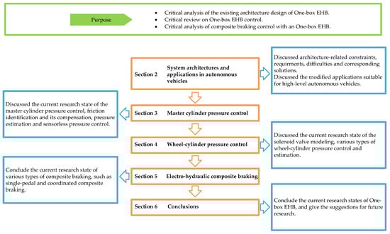
Figure 1.
A structured overview of this review work.
Table 1 is the summary of the important concepts in the paper.

Table 1.
Summary of important concepts.
2. System Architectures and Applications in Autonomous Vehicles
2.1. System Architectures
Hydraulic circuit design is the focus of One-box EHB system design. The new requirements placed on the braking system have caused tremendous changes in the traditional hydraulic circuit and brought new problems and challenges. How to realize many functions such as service brake, brake decoupling, pedal feel simulation, wheel-cylinder pressure modulation, failure backup, and so on in a small volume has become a hot issue focused by researchers.
Continental Teves AG & Co. OHG [7] and Robert Bosch GmbH [8] disclosed a structure and control method of One-box EHB. Figure 2 is the architecture diagram of this kind of One-box EHB. The structure includes a reservoir, a tandem master cylinder, a brake pedal position sensor, a pedal feel simulator, a pressure-building unit, two pressure sensors, and 14 solenoid valves. The 14 solenoid valves are divided into eight inlet valves and outlet valves for wheel-cylinder pressure modulation, two piston separation valves for separating the pressure-building unit and wheel-cylinders, two circuit separation valves for separating the tandem master cylinder and wheel-cylinders, a simulator separation valve for separating the pedal feel simulator from the tandem master cylinder, and a test valve for self-test. The pressure-building unit consists of a motor, transmission mechanisms, and a cylinder with a piston. During normal operation, the piston separation valves are powered on and opened, and the circuit separation valves are powered on and closed. After the driver presses the brake pedal, the brake fluid in the tandem master cylinder flows into the pedal feel simulator, thereby producing a pedal feel. After the controller monitors the driver’s braking intention through the brake pedal position sensor, it drives the motor of the pressure-building unit to push the piston and push the brake fluid in its cylinder into the wheel-cylinders to generate corresponding hydraulic braking force. If the system fails, after the driver presses the brake pedal, the brake fluid in the tandem master cylinder flows directly into the wheel-cylinders, thereby generating secondary braking force.
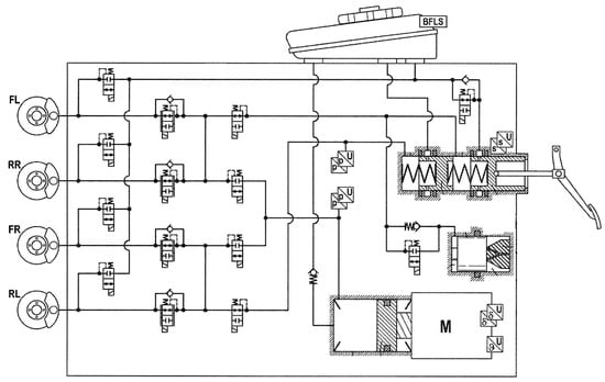
Figure 2.
System Architecture from Continental [7]. (BFLS—Brake Fluid Level Sensor; FL—Front Left; RR—Rear Right; FR—Front Right; RL—Rear Left; M—Motor).
However, this structure has certain flaws. The fluid outlet from the outlet valves is directly connected to the reservoir. When the ABS triggers the wheel pressure reduction logic, the brake fluid in the wheel-cylinder flows directly back to the reservoir. If the ABS is triggered for a long time during a single braking process, such as braking at a low-mue road at a high vehicle speed, the brake fluid in the cylinder of the pressure-building unit will continue to flow back to the reservoir through the outlet valves, which may result in insufficient brake fluid reserve in the pressure-building unit, resulting in loss of braking force building capability. Therefore, special control methods need to be designed to deal with this situation. The usual practice is to monitor the piston position of the pressure-building unit in real-time when the ABS is triggered. If the piston moves too long, close the piston-separating valves at the appropriate time and control the piston to pull back so that the pressure-building unit can replenish brake fluid through the check valve connected in series between the pressure-building unit and the reservoir. After the fluid replenishment is completed, reopen the piston-separating valves, and the pressure-building unit will continue to build pressure. During this fluid replenishment process, the four wheel-cylinders can only hold pressures or decrease pressures but do not have the ability to increase pressures. Therefore, it will cause a short-term lack of braking force and prevent the vehicle from reaching the maximum deceleration.
In order to solve this problem, ZF Active Safety US Inc. (Livonia, MI, USA) [9] disclosed a structure and control method of One-box EHB. Figure 3a is the architecture diagram of this kind of One-box EHB. When the pressure-building unit moves forward, part of the brake fluid in the front chamber of the pressure-building cylinder enters the wheel-cylinders, and the remaining part of the brake fluid in the front chamber of the pressure-building cylinder flows into the rear chamber of the pressure-building cylinder through the circuit. At this time, the effective area of the pressure-building cylinder is the minor diameter of the piston. If it monitors that the piston movement distance is too long, the front chamber-separating valve is controlled to close, and the piston is controlled to pull back. At this time, the front chamber of the piston can be replenished with fluid through the check valve, while at the same time, the brake fluid in the rear chamber of the piston can still enter the wheel-cylinders to continue building pressure, thus achieving uninterrupted pressure-building process during the fluid replenishing process. At this time, the effective acting area of the pressure-building cylinder is the area of the major diameter of the piston minus the area of the minor diameter of the piston. After the fluid replenishment is completed, the front chamber-separating valve is controlled to open, the piston is controlled to move forward, and the normal pressure-building process is continued. At the same time, the major and minor diameters of the piston are reasonably set so that the effective area of the piston to build pressure in the pull-back direction is smaller than that in the forward direction. If maintaining pressure in the pull-back direction, since the effective area is smaller, the motor output torque can be smaller, thereby reducing the load on the motor and transmission mechanism, reducing heat generation and extending the durability of the system. In addition, this structure uses a two-position three-way solenoid valve to replace the functions of a pair of piston-separating valves and circuit-separating valves, thereby saving part of the structural space and material costs.
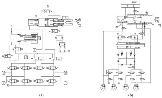
Figure 3.
(a) System Architecture from ZF [9] (T1—Terminal 1 of the reservoir; T2—Terminal 2 of the reservoir; T3—Terminal 3 of the reservoir; T—Travel sensor; S—Position sensor; P—Pressure sensor; LR—Left Rear; RF—Right Front; RR—Right Rear; LF—Left Front); (b) System Architecture from Hl Mando [10] (PS—Pressure Sensor).
Hl Mando Corporation [10] disclosed the structure and control method of a One-box EHB. Figure 3b is the architecture diagram of this kind of One-box EHB. This structure allows three different pressure-building modes. Figure 4 is the diagram of this pressure-building unit and its effective area of different modes. Under normal circumstances, the piston moves forward, and all the brake fluid in the front chamber of the pressure-building unit flows into the wheel-cylinders. At this time, the effective area of the piston is the largest, which is the area of the front area of the piston; when in the second working mode, the piston moves backward, and all the brake fluid in the rear chamber of the pressure-building unit flows into the wheel-cylinders. At this time, the effective area of the piston is the area of the right area of the piston; in the third working mode, the piston moves forward, but part of the brake fluid in the front chamber of the pressure-building unit enters the wheel-cylinders, and the other part enters the rear chamber of the pressure-building unit. At this time, the effective area of the piston is the difference between the front and rear area of the piston.
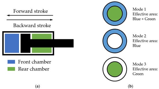
Figure 4.
(a) Diagram of the pressure-building unit; (b) Effective area of different modes.
Additionally, there is another problem with these structures. When a single-circuit leakage failure occurs in a conventional braking system, after the brake is applied, the chamber corresponding to the failed circuit in the tandem master cylinder cannot generate brake hydraulic pressure and will be completely compressed to the mechanical limit as the master cylinder piston moves. When the failed chamber is fully compressed, and the master cylinder piston continues to be pushed, the brake hydraulic pressure can continue to be established in the non-failed chamber, thus ensuring half of the braking force. However, for One-box EHB, during normal operation, the pressure-building cylinder has only one chamber and is responsible for both circuits at the same time. If a single-circuit leakage failure occurs at this time, if no special action is taken, the piston of the pressure-building unit will be completely compressed, and all four wheels will be unable to establish braking force, resulting in a complete loss of braking force, which is unacceptable.
Therefore, it is required to quickly and accurately identify leakage conditions during the braking process. Mando Corporation [11] disclosed a self-checking method that can check whether the original master cylinder leaks during the system self-checking process. Hyundai Mobis Co., Ltd. (Seoul, Republic of Korea) [12] disclosed a method of detecting leaks based on pressure changes in hydraulic circuits. Figure 5 is the architecture diagram of these two kinds of One-box EHB. During the pressure-building process, the piston of the pressure-building unit moves forward so that the generated pressure reaches the target pressure. When it is detected that the piston displacement reaches a specific threshold and the difference between the target pressure and the actual pressure is greater than another threshold, it is determined that a leak has occurred. At this time, the circuit of the rear wheel brake is closed, and a pressure higher than the target pressure is generated at the front wheel to achieve the braking request under normal conditions. At this time, the front wheel pressure and piston displacement are continuously monitored. If the difference between the target pressure and the actual pressure is greater than the threshold, it is determined that the circuit of the front wheels is leaking; otherwise, it is determined that the circuit of the rear wheels is leaking.
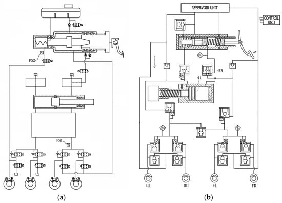
Figure 5.
(a) System architecture from Mando [11] (PS—Pressure Sensor); (b) System architecture from Mobis [12].
At the same time, researchers have conducted a series of studies on how to achieve better failure backup after a single-circuit leakage failure is detected. When the software detects a single-circuit leakage failure, the usual approach is to immediately switch to the fail-back mode, and the tandem master cylinder connected to the brake pedal builds pressure on all four wheels. At this time, due to the inherent characteristics of the tandem master cylinder, half of the braking force can be generated by the normal circuit in this case. Braking regulations [13] require that in this case, with a brake pedal force of 500 N, the vehicle deceleration still needs to reach at least 2.44 m/s2, so the brake pedal lever ratio, the diameter and stroke of the tandem master cylinder and other parameters of the brakes need to be reasonably designed to meet regulatory requirements. Mando Corporation [14] disclosed a control method after a leak occurs. When a leak occurs, the driver’s deceleration intention is monitored through the pedal displacement sensor, and based on the intensity of the deceleration intention, the inlet valves of the leakage circuit are switched to be closed, thereby cutting off this circuit and inhibiting further leakage. Continental Teves AG & Co. OHG (Frankfurt, Germany) [15,16,17] disclosed a new type of One-box EHB. The master cylinder connected to the pedal has been changed from a tandem master cylinder to a single-chamber master cylinder, which can control two wheel-cylinders in one circuit, while the pressure-building unit can control two wheel-cylinders in another circuit. There is a circuit separation valve between the two circuits. By controlling its opening and closing, the two circuits can be connected or disconnected. At the same time, a brake fluid level sensor is installed at the reservoir. When the brake leakage tendency is detected by the brake fluid level sensor, the control circuit separation valve closes. At this time, one circuit is controlled by the brake master cylinder, and the other circuit is controlled by the pressure-building unit. No matter which circuit fails, the backup braking force can be generated. If the circuit corresponding to the pressure-building unit does not fail, since the pressure-building unit can generate higher brake hydraulic pressure, the failure backup deceleration can reach much higher than 2.44 m/s2.
Table 2 shows the summary of the One-box EHB architecture design.
Table 2.
Summary of One-box EHB architecture design.
2.2. Applications in Autonomous Vehicles
SAE (Society of Automotive Engineers) International [23] has released classification standards for autonomous driving. This standard divides autonomous driving into six levels, L0 to L5, to clarify the differences between different levels of autonomous driving technology. Among them, the L3 level is the watershed of autonomous driving. Autonomous driving systems at levels above L3 take over from human drivers and need to complete monitoring of the surrounding environment. High-level autonomous driving systems require the vehicle to complete all operations on its own without requiring the driver to take over. Therefore, there is a need for redundant backup of the active braking system. Due to the advantages of One-box EHB’s ability to actively establish braking force, such as fast response speed, high control accuracy, and a large built-up pressure, it is widely used in advanced driving assistance systems of L2 and below levels and is used as a critical brake actuator for functions such as adaptive cruise control, automatic emergency brake, and automatic parking assist. However, a single One-box EHB cannot complete the failure backup function during pure active braking. Therefore, it is necessary to study the redundant braking system architecture based on One-box EHB considering the characteristics of high-level autonomous driving systems.
Urs Bauer et al. [24] believe that when the normal braking system fails, the redundant braking system needs to take over from the human driver to complete the braking operation. Therefore, the redundant braking system needs to be able to complete the braking operations that the human driver can complete. At the same time, the authors believe that human drivers should be able to achieve service braking and single-channel longitudinal braking stability control but often cannot complete lateral stability control. This defines the capability and responsibility boundaries of the redundant braking system. Therefore, Robert Bosch GmbH (Stuttgart, Germany) [25] proposed a redundant braking system solution suitable for high-level autonomous driving. Figure 6a is the architecture diagram of this kind of One-box EHB. This solution mainly consists of a service braking unit and a second braking unit. When the system is operating normally, the service brake unit completes all braking functions, including brake booster, longitudinal and lateral stability control, and comfortable functions, while the second braking unit does not work. When the service brake unit fails, the second braking unit takes over and can build up braking pressure on all four wheels. When the second braking unit monitors that the wheel is locked, it can decrease the pressure of the circuit where the locked wheel is located and perform dual-channel longitudinal braking stability control.
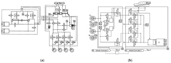
Figure 6.
(a) System architecture from Bosch [25]; (b) System architecture from Continental [26] (IPB—Integrated Parking Brake).
Continental Automotive Systems, Inc. (Auburn Hills, MI, USA) [26] disclosed a redundant braking system solution suitable for high-level autonomous driving. Figure 6b is the architecture diagram of this kind of One-box EHB. When the service brake system completely fails, the second braking unit can build pressure on the two front wheels and can decrease the pressure of a single front wheel when it locks. At the same time, this solution provides multi-level limp strategies under different degrees of system failures. Its fault redundancy strategy is more flexible and can fully utilize the system’s remaining capabilities. When the service brake system only has a failure in pressure-building capacity while its solenoid valves are working normally, the second braking unit can brake all wheels and control their slip rates. Pieces of the literature [27,28] also published similar solutions.
The above solutions all implement the braking redundancy function in two architectures that are physically distant from each other. Mando Corporation is studying the possibility of achieving brake redundancy in a separate structure. The literature [29] discloses the structure of a motor with redundant capabilities. The motor in the pressure-building unit has two independent windings and drivers. When any winding or driver fails, the controller can still control the other one to perform braking. Due to the size of the motor, when one winding fails, the motor’s power assistance will become smaller. At this time, the effective area of the piston is adjusted by adjusting the internal flow channel, thereby amplifying the motor’s output and achieving normal braking force. The literature [30] discloses the structure of two electronic control units enclosed in one housing, each of which has the redundant capability, which has two independent printed circuit boards, MCUs, and motor position sensors. When one of the electronic control units fails, the other electronic control units can perform the same function, thereby completing the fault redundancy.
Table 3 shows the summary of One-box EHB architecture for high-level autonomous vehicles.
Table 3.
Summary of One-box EHB architecture for high-level autonomous vehicles.
3. Master Cylinder Pressure Control
As a replacement for the traditional vacuum booster, One-box EHB is required to undertake conventional service braking functions. It also needs to take the responsibilities of electro-hydraulic coordinated composite braking control, active emergency braking, and vehicle comfort braking functions. Therefore, the robust and precise control of the master cylinder pressure is very important, and its control quality will directly affect driving safety and comfort. However, the One-box EHB system is relatively complex. The mechanical, electronic, and hydraulic parts are coupled with each other. The whole system has many links and long chains. There are many nonlinear factors, time-varying factors, and external disturbances. The robust and precise control of hydraulic pressure is a big challenge. Therefore, researchers have conducted a lot of research on this topic.
3.1. Pressure Control
The braking system has pressure–volume (PV) characteristics; that is, the braking system has a certain hydraulic stiffness, and the pressure of the system obeys a specific relationship with the volume of brake fluid entering the braking system from the brake master cylinder. Therefore, by controlling the stroke of the master cylinder, the pressure of the brake system can be controlled. I.-J. Yang et al. [31] designed a master cylinder stroke control algorithm, and experiments proved that the algorithm can achieve fast and comfortable braking.
However, for master cylinder pressure control, master cylinder stroke control is indirect and belongs to open-loop pressure control. Since the PV characteristics of the braking system will be affected by the external environment and disturbances, simple master cylinder stroke control cannot meet the pressure control accuracy requirements of One-box EHB, and a feedback control algorithm for the master cylinder pressure still needs to be studied. Fabio Todeschini et al. [32] developed a hybrid position-pressure switching controller. At the beginning of the control, the position controller is deployed; when the pressure approaches the target, the controller switches to the pressure control.
The EHB system has nonlinear characteristics, and it is difficult to establish an accurate mathematical model of the system. Zhizhong Wang [33] et al. developed a gain-scheduling PI controller to control the actuator. Lei Chen et al. [34] used the error and error derivatives as input variables to design a fuzzy incremental PID controller for hydraulic pressure control.
A cascade controller connects multiple controllers in series. Among them, the primary control object is the control object of the entire system, and the secondary control object is related to the primary control object. By introducing the secondary controller, the disturbance on the secondary control object can be overcome; thereby, the secondary controller can cooperate with and complement the primary controller to improve the control effect. The EHB system has a long control chain. By reasonably designing multi-level series controllers, the disturbances in each controller can be effectively suppressed, thereby improving the hydraulic pressure control effect.
Jian Zhao et al. [35] designed a four-step cascade brake pressure controller based on pressure-position-speed-current. Among them, the pressure control adopts open-loop control according to the PV characteristics of the braking system; the position and speed closed-loop controller adopts PI controller; the d-axis current in the current controller adopts PI control; and the q-axis current adopts MPC control.
However, due to the high nonlinear characteristics in the EHB system and hydraulic circuit, the traditional PID controller is not fully capable of pressure control, and the use of PID controllers in multiple cascade closed-loop controls requires a lot of calibration work, which results in difficulties in engineering practice. To solve these problems, Weihong Yang et al. [36] designed a pressure-position-current cascade controller. Among them, the pressure controller adopts the fuzzy PI algorithm based on feedforward. Experiments show that compared with traditional PID control, this algorithm can effectively improve the control effect of hydraulic pressure.
On this basis, Jian Zhao et al. [37] further proposed a pressure-position-current cascade control algorithm. In order to solve the harmful effects of the dynamic friction in the mechanism, the large inertia of the system, and the nonlinear characteristics of the hydraulic system on the control, the authors introduced a three-step nonlinear control method in the position closed-loop control and decomposed the nonlinear control problem into static control, feedforward control based on reference dynamics and state-dependent feedback control. Hardware-in-the-loop (HiL) experiments prove that this control algorithm can effectively improve control accuracy and response speed.
The EHB system and the ABS system are interrelated and together form a complete automotive braking system. When the ABS is working, during the pressure decrease process of ABS control, the brake fluid will be pumped from the wheel-cylinder back to the EHB’s master cylinder; during the pressure increase process of ABS control, the brake fluid will be poured from the EHB’s master cylinder into the wheel-cylinder. The modulation process of wheel-cylinder pressure will cause the master cylinder pressure to fluctuate violently, causing noise and affecting the durability of the system. Therefore, it is important to consider master cylinder pressure control during ABS activation. Jingtian Wang et al. [38] proposed that during the ABS control process, the EHB needs to provide a pressure greater than the four-wheel wheel-cylinder pressure in real-time, but it needs to be smaller than the hydraulic pressure required by the driver. The real-time pressure of the four-wheel-cylinder is obtained by installing four wheel-cylinder pressure sensors, and based on the rules, the maximum wheel-cylinder pressure envelope value and the maximum wheel-cylinder pressure pre-charge value are designed as the target input of the EHB master cylinder pressure. The authors then proposed a three-closed-loop pressure optimization control strategy of master cylinder pressure-piston displacement-motor current. HIL experiments show that under different road adhesion conditions, this strategy can effectively reduce pressure fluctuations when ABS is activated without affecting the control performance of ABS itself.
3.2. Friction Model and Its Compensation
The mechanical transmission mechanism of EHB comes in many forms, but all of them have the nonlinear characteristic of friction, which causes crawling, dead zone, oscillation, and other problems in the master cylinder hydraulic pressure control process. However, system friction is a nonlinear time-varying disturbance, which is affected by external factors such as the piston speed, piston movement direction, transmission load, and temperature, causing difficulties in pressure control. How to accurately model system friction and eliminate or compensate for the effects of friction through control methods is a major challenge in EHB hydraulic pressure control.
3.2.1. Experiments and Identification
Bing Wang et al. [39] proposed an EHB friction model that combines static friction and viscous friction. When testing static friction, control the motor to slowly increase the current. The motor torque, when the motor’s speed changes from 0 to a non-zero value, is the static friction of the system. When testing viscous friction, control the motor to move at a constant speed at different speeds. The measured motor torque at different speeds is the viscous friction of the system.
Ricardo de Castro et al. [40] studied the characteristics of the internal friction of the EHB through a slow ramp experiment of the motor current and found that due to the existence of static friction, the hydraulic force has a crawling phenomenon. In addition, the size of the friction force is related to the load, and the friction force is much larger than the load, which shows that friction force disturbance plays an important role in the EHB control system.
On this basis, Yuan Ji et al. [41] added the motor current slow sine experiment and obtained the kinetic friction and static friction curves. They found that the kinetic friction and static friction are asymmetrical with respect to the motor speed direction, and have a linear relationship with the load. At the same time, there is a nonlinear relationship between dynamic friction and piston speed. On this basis, the authors propose an asymmetric continuous friction model, which combines the continuity advantages of the Lure model and introduces linear load-dependent nonlinear characteristics.
Wei Han et al. [42] conducted an in-depth study on the relationship between friction force, piston position, and motor speed under the conditions of pressure increase and pressure decrease. By controlling the piston to move at a constant speed at different speeds, the friction relationship under different conditions is obtained through experiments, and it is concluded that the relationship between friction and rotational speed obeys Coulomb friction, viscous friction, and Stribeck effect, and has load-dependent properties. Also, there is friction asymmetry during the pressure increase and decrease processes. In order to reduce the difficulty of identifying friction model parameters, the authors chose to compensate based on Coulomb friction and viscous friction models.
Considering the balance between model accuracy and refinement, Zhentao Chen et al. [43] used the Karnopp friction model to describe the system friction characteristics of EHB. Since experiments show that break-away force and slip friction are positively related to hydraulic pressure, hydraulic force is introduced into the Karnopp friction model. The parameters of the model were identified through experiments with slowly increasing current.
3.2.2. Compensation and Control
After considering Coulomb friction, viscous friction, and Stribeck effect, combined with the influence of hydraulic load, Ricardo de Castro et al. [40] designed a friction map model and approximated it through a linear-in-the-parameter model. Experimental results show that the friction model has certain effectiveness and performance, can reduce fitting errors, and can allow a certain degree of parameter uncertainty.
Since the Coulomb friction and viscous friction models ignore static friction, Wei Han et al. [42] introduced high-frequency sinusoidal flutter signal compensation to eliminate the influence of static friction. At the same time, due to the introduction of model-based friction compensation, the amplitude of the flutter compensation can be very small, thus ensuring the comfort of braking. Finally, the authors fuse the sliding mode controller with the conditional integrator.
The system has disturbances such as model mismatch, time-varying parameters, and unexpected disturbances. Zhentao Chen et al. [43] designed a disturbance observer and proposed an explicit model predictive controller. Experiments show that this control method improves hydraulic pressure control accuracy and disturbance suppression capabilities, and the real-time performance of the algorithm is verified on the microchip.
Table 4 shows the summary of master cylinder pressure control schemes.
Table 4.
Summary of master cylinder pressure control schemes.
3.3. Pressure Estimation and Sensorless Pressure Control
The pressure sensor is a key component of the EHB system, providing master cylinder pressure signal feedback for EHB to carry out precise pressure control. However, the unit price of the pressure sensor is relatively high. If the master cylinder hydraulic pressure can be accurately estimated through the pressure estimation algorithm, the pressure sensor can be omitted, reducing the cost of the EHB and improving product competitiveness. In addition, if the pressure sensor fails, the EHB must rely on the pressure estimation algorithm for redundant braking. Therefore, it is very necessary to study the master cylinder hydraulic pressure estimation and master cylinder pressure control without a hydraulic pressure sensor providing a feedback signal.
The position of the master cylinder piston can be calculated by the angle of motor rotation together with the transmission ratio of the system. The torque output by the motor can be calculated by the motor current. These two signals are the main basis for estimating the master cylinder pressure. Wei Han et al. [53] established a control-oriented system model for EHB and regarded the dead zone of static friction, Coulomb friction, and PV characteristics as disturbances. Based on this model, an interconnected pressure estimator is designed, which includes an estimator and a nonlinear parameterized disturbance observer.
However, there are many uncertain signals when estimating the master cylinder hydraulic pressure. The PV characteristics of the system are affected by the direction and speed of the piston movement. The friction of mechanical structures is affected by temperature, pressure, and speed. These uncertain disturbances bring greater challenges to the accurate estimation of master cylinder pressure. The master cylinder pressure cannot be accurately estimated through a single PV characteristic curve or system dynamics model. Wei Han et al. [54] proposed a master cylinder pressure estimator based on actuator characteristics and vehicle dynamics. The dynamics of wheel rotation are obtained through the wheel speed sensor, and the pressure is estimated based on the vehicle and wheel dynamics models. Compared with the estimator based only on actuator characteristics, the estimation accuracy of the joint estimator is improved, and the performance and robustness of the control method are verified through experiments.
The friction coefficient varies greatly during the braking process and will thus affect the pressure estimation by vehicle and wheel dynamics. Biaofei Shi et al. [55] obtained a modified brake line friction coefficient model through a large number of real vehicle braking tests under different initial brake disc temperatures, different vehicle speeds, and different braking pressures. The master cylinder pressure is estimated based on vehicle longitudinal dynamics and wheel dynamics, and the estimation method can adapt to road gradient changes with the help of inertial sensors.
4. Wheel-Cylinder Pressure Control
The brake-by-wire system must have the ability to independently modulate the four-wheel braking forces to achieve ABS, TCS, AYC, and other functions. Using solenoid valves to control brake hydraulic pressures is a reliable and low-cost solution and is widely used in hydraulic-based brake-by-wire systems. Each wheel brake is equipped with a pair of an inlet valve and an outlet valve, which can increase, hold, and decrease the wheel-cylinder pressure. The control quality of the inlet valve and the outlet valve determines the accuracy of wheel-cylinder pressure control and is the most important actuator for wheel-cylinder pressure control. Therefore, many researchers have conducted a lot of research on wheel-cylinder pressure control based on solenoid valves.
4.1. Modeling of Solenoid Valves
The solenoid valve system is a dynamic system coupled with multiple physical fields such as electromagnetic field, flow field, temperature field, and structural field. However, solenoid valves have many small parts and are fully enclosed. Directly observing various physical quantities in solenoid valves through experiments is very complex and costly. Therefore, the researchers chose to accurately model the solenoid valve system to deepen their understanding of the controlled object. Figure 7 is the typical architecture diagram of a solenoid valve.
Xiang Gao et al. [56] established a nonlinear dynamic model of the solenoid valve based on theoretical analysis and finite element simulation. The model consists of three sub-models, namely the mechanical sub-model, the electromagnetic sub-model, and the fluid dynamics sub-model. These sub-models are coupled through force and valve spool displacement. The mechanical model is a single-degree-of-freedom mass-spring-damper system that follows Newton’s second law. Electromagnetic models are divided into electric field models and magnetic field models. The electric field model is a resistance-inductance system and follows Kirchhoff’s law; the magnetic field model follows Kirchhoff’s second law of the magnetic circuit and is represented by two-dimensional finite element simulation results. For the fluid dynamics sub-model, the valve spool is mainly affected by hydrostatic force, hydraulic force, and viscous force. The fluid momentum of the control body of the valve is analyzed, and the adaptation parameters are analyzed through finite element analysis to obtain the hydraulic force on the valve spool. Through experimental verification, this model has high accuracy and can be used to help study wheel-cylinder pressure control strategies.

Figure 7.
Structure of the solenoid valve [57].
Figure 7.
Structure of the solenoid valve [57].

Aihong Meng et al. [57] established a flow field simulation model through CFD tools and conducted joint simulation with the brake model built with AMESim, so they obtained the dynamic pressure and opening data of the solenoid valve under real working conditions. The simulation model can be used as a reference for control strategy optimization.
4.2. High-Frequency On-Off Control
The main control actuator for wheel-cylinder pressure control is the inlet valve. The inlet valve is a two-position, two-way solenoid valve. When the coil is powered off, the valve spool is in the fully open position by the restoring force of the spring, allowing brake fluid to flow into the wheel-cylinder; when the coil is powered on, the electromagnetic force overcomes the spring force, and drive the spool into the closed position, and brake fluid cannot flow into the wheel-cylinder. Through the high-frequency pulse control of the coil, the valve spool is quickly switched between the fully open and fully closed positions, and the time period of each opening is controlled so that a very small amount of brake fluid enters the wheel-cylinder during the opening process, so that the wheel-cylinder braking pressure can be finely adjusted.
Aldo Sorniotti et al. [58] tested the step response of the inlet valve on the HiL brake test bench and completed the ABS anti-lock simulation experiment verification based on the high-frequency switching control method. Kevin O’Dea [59] simulated ABS based on high-frequency switch control. The experimental results showed that the estimation accuracy of wheel-cylinder pressure estimation using solenoid valves did not affect the ABS braking performance. The high-frequency switch control has high robustness to the upper layer vehicle braking stability algorithm. Ding Nenggen et al. [60] measured the inlet valve characteristics under different pressure increase–hold cycles and found that rapid switching of pressure states can be achieved by using different increasing and holding times, and the pressure increase rate can be flexibly controlled. This enables fine regulation of wheel-cylinder pressure increase.
Zhicheng Chen et al. [61] studied the impact of PWM frequency on control under high-frequency switching control and believed that the working range of lower frequencies is wider, but the control effect within the control cycle is poor; the working range of higher frequencies is narrower, but the control effect within the control loop is better. At the same time, the characteristics of the solenoid valve under different duty cycles were further studied, and it was found that there was a delay during the pressure increase process. In order to make the wheel-cylinder pressure increase delay as small as possible, a larger pressure increase rate is required. However, a large pressure increase rate can easily cause overshoot and oscillation. Therefore, the authors proposed a variable gain PID controller. When the hydraulic pressure control error is large, the controller gain is relatively large; when the hydraulic pressure control error is small, the controller gain is relatively small. Experimental results show that the controller can achieve rapid pressure increase when the hydraulic pressure tracking error is large and can achieve precise control when the hydraulic pressure tracking error is small.
The high-frequency switching control frequency of solenoid valves is generally around 10–100 Hz, which is easy to implement, simple to control, and has high robustness. However, under this control strategy, the solenoid valve is in a high-frequency switching state, and its valve spool switches back and forth between the fully open and fully closed positions, rapidly hitting the mechanical limits on both sides, which will cause noise. At the same time, the hydraulic pressure increases step by step under high-frequency switching, and the control is relatively rough, making it impossible to finely adjust the wheel braking force and slip rate. At the same time, during the process of closing the valve, hydraulic pressure oscillation will occur due to the water hammer effect, which will have a negative impact on hydraulic pressure control, noise, and pedal feel.
4.3. Pressure Difference Control
When the valve spool of the solenoid valve is in the closed position, the spool is subject to electromagnetic force, hydraulic force, spring restoring force, and valve seat support force. The hydraulic force comes from the pressure difference between the master cylinder and the wheel-cylinder. If the electromagnetic force applied to the valve core happens to be balanced with the hydraulic force and spring restoring force, although the valve core and the valve seat are in contact, there is no interaction force between them, and the valve spool is in a critical state. In this critical state, keep the electromagnetic force unchanged, and continue to increase the hydraulic pressure of the master cylinder, the hydraulic pressure on the valve core will become larger, the force balance of the spool will be broken, and it will leave the valve seat and move in the opening direction. At this time, the brake fluid enters the wheel-cylinder from the master cylinder. As the wheel-cylinder pressure gradually increases, the hydraulic pressure on the spool gradually becomes smaller until it returns to the original equilibrium state and the spool returns to the critical state again. Since the electromagnetic force does not change at this time, the hydraulic pressure difference does not change either; that is, the pressure difference at both ends of the spool does not change. In other words, the coil current and electromagnetic force are in one-to-one correspondence with the pressure difference across the spool. Under the premise that the master cylinder pressure can be obtained through the sensor, the wheel-cylinder pressure can be controlled in an open loop by controlling the current, which also provides a new method for wheel-cylinder pressure control.
Junzhi Zhang et al. [62] conducted theoretical analysis and simulation verification on this critical state pressure difference control method. The results showed that there is a linear relationship between the coil current and the critical pressure difference, but it takes a certain time to reach the critical pressure difference. In addition, the authors also found through simulation experiments that although the mass of the valve spool has no effect on the critical pressure difference, it will significantly extend the time for the valve core to reach the critical state. At the same time, Junzhi Zhang et al. [63] verified through HiL experiments that compared with traditional PWM control, this critical pressure difference control method has higher accuracy in controlling brake hydraulic pressure. Figure 8 shows the details of the valve spool and seat and the linear relationship between the coil current and the critical pressure difference.
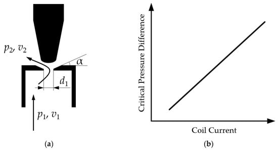
Figure 8.
(a) Details of valve spool and seat; (—inlet fluid pressure; —inlet fluid velocity; —seat orifice diameter; —outlet fluid pressure; —outlet fluid velocity; —seat angle;) (b) Linear relationship between the coil current and the critical pressure difference.
In fact, open-loop control of wheel-cylinder pressure using only critical pressure difference characteristics cannot meet the requirements of dynamic adjustment of wheel-cylinder pressure by upper-level algorithms such as ABS. Passively waiting for the brake hydraulic pressure to reach the critical state takes a long time, and other control methods need to be combined to meet the upper-level control’s demand for rapid response to hydraulic pressure. Houhua Jing et al. [64] added PID feedback control based on the critical pressure difference characteristics and achieved better target hydraulic follow response speed and control accuracy.
Since the solenoid valve has manufacturing errors and the working conditions, such as ambient temperature change in real-time, and it may be affected by external disturbance, using critical pressure difference characteristics for open-loop control will also lead to low control accuracy. The use of closed-loop feedback control can better compensate for uncertain external changes, and the hydraulic pressure control has high robustness. In order to achieve stronger control robustness and control accuracy and to compensate for valve inconsistencies and external disturbances, Chen Lv et al. [65] introduced a hydraulic pressure control algorithm based on sliding mode control on the basis of retaining the original open-loop critical pressure difference characteristic control. Experiments show that this control algorithm that combines critical pressure difference characteristics and sliding mode control has higher hydraulic control accuracy and control robustness than pure critical pressure difference characteristic control or simple sliding mode control.
4.4. Valve Spool Displacement Control
The wheel-cylinder has PV characteristics; that is, there is a certain relationship between the pressure of the wheel-cylinder and the volume of brake fluid entering the wheel-cylinder. If the volume of brake fluid entering the wheel-cylinder can be controlled, the pressure in the wheel-cylinder can be dynamically controlled. The flow rate through the inlet valve is not only related to the pressure difference between the two ends of the spool but also related to the displacement of the spool. According to the law of orifice throttling flow rate equation, the greater the valve core displacement, the greater the flow rate. If the valve core displacement can be well controlled, the flow rate of the inlet valve can be effectively controlled, thereby controlling the pressure of the wheel-cylinder. Therefore, the wheel-cylinder pressure control problem can be converted into a spool displacement control problem.
WANG Weiwei et al. [66] established a control simulation model of the inlet valve. Through simulation, they studied how the valve spool can be suspended at a certain position with different duty ratios under 2~4 kHz frequency PWM control, thus achieving the goal of achieving the third spool state other than fully open or fully closed in the traditional high-frequency switch control. This method broadens the functional application range of the inlet valves and provides a reference for further improving the accuracy of wheel-cylinder pressure control.
Xun Zhao et al. [67] designed a nonlinear sliding mode observer for the spool displacement based on the voltage and current of the coil and obtained the brake fluid flow through the hydraulic model of the solenoid valve and the braking system. Taking into account the nonlinear characteristics of electromagnetic force, hydraulic force and solenoid valve flow under different valve spool openings, a sliding mode controller is designed to adjust the valve spool position to accurately linearly control the wheel-cylinder pressure. Tests show that this method can effectively linearly control the wheel-cylinder pressure, enable the low-cost on–off valve to function as a proportional valve and reduce noise and pedal vibration.
Zhao Xiangyang et al. [68] established a mathematical model of the solenoid valve, established the state equation of the solenoid valve, used the root mean square volume Kalman filter algorithm to estimate the valve spool position of the solenoid valve, and calculated brake fluid flow and wheel-cylinder pressure based on this estimated valve spool position. Then, a spool position controller is designed based on the sliding mode variable structure control algorithm. HiL experiments show that the wheel-cylinder pressure estimation is accurate, and the control algorithm can accurately track the control target.
Table 5 shows the summary of wheel-cylinder pressure control schemes.
Table 5.
Summary of wheel-cylinder pressure control schemes.
4.5. Wheel-Cylinder Pressure Estimation
There are usually two ways to estimate wheel-cylinder pressure: one is estimating actuator characteristics through solenoid valves and pressure models, and the other is estimating braking force based on tire models and wheel dynamics. The estimation method based on actuator characteristics is interfered with by the consistency of the actuator and unknown external disturbances, and there is error accumulation. Estimation methods based on wheel dynamics are affected by vehicle and brake system model accuracy and actual signal oscillations. A single method cannot accurately estimate wheel-cylinder pressure. Qixiang Zhang et al. [69] designed a wheel-cylinder pressure estimation algorithm based on the orifice throttling flow rate equation and wheel-cylinder PV characteristics. Guirong Jiang et al. [70] used the extended Kalman filter to combine the two estimation methods and used wheel speed variables as observed variables to correct the hydraulic model. Experimental results show that this method can accurately estimate the wheel-cylinder pressure during the wheel-cylinder pressure regulation process.
Haichao Liu et al. [71] established a solenoid valve hydraulic model and a wheel dynamics model and combined the two models to design a wheel-cylinder hydraulic pressure estimation algorithm based on the extended Kalman filter. Experiments show that this method shows high estimation accuracy in both the overall trend and the process of hydraulic pressure changes.
Lingtao Wei et al. [72] established a linear valve model and a switch valve model, respectively, based on the characteristics of solenoid valves. The two models were respectively subjected to Kalman filtering with the tire longitudinal force model based on slip rate and adhesion coefficient, and the two were fused using the IMM model to obtain the estimated wheel-cylinder pressure. Real vehicle experimental results show that the linear valve model is more accurate in most cases, while the switch valve model is more accurate under high hydraulic conditions, and the IMM fusion estimation algorithm can achieve higher precision wheel-cylinder hydraulic pressure estimation than the Kalman filter alone.
4.6. Four Wheel Pressures Coordinated Control
The method of independently controlling the four-wheel-cylinder pressures of the One-box EHB system is different from that of traditional ESC. Under the traditional ESC architecture, the back pressure for wheel-cylinder pressure modification is provided by the motor driving the plunger pump. When increasing the pressure, the brake fluid pumped by the plunger pump flows into the wheel-cylinder through the inlet valve; when decreasing the pressure, the brake fluid flows out of the wheel-cylinder and flows into the accumulator through the outlet valve and is pumped back to the original circuit by the plunger pump to participate in the circulation of brake fluid. During this process, the two circuits are independent of each other, and the back pressures of the inlet valves of the two wheel-cylinders in each circuit are the same and need to be modified independently. For the traditional ESC architecture, because the pressure of the plunger pump fluctuates and the control accuracy is poor, it is only necessary to maintain a high back pressure through the plunger pump, and the fine modification of the wheel-cylinder pressures is completed by the fine control of the solenoid valves.
As for the One-box EHB system, since the pressure increase in the pressure-building unit is generated by a high-performance motor-driven transmission mechanism that directly pushes the hydraulic cylinder piston, its hydraulic pressure control accuracy is high and does not produce pressure fluctuations and noise when the building pressure. Moreover, the One-box EHB system is equipped with a hydraulic pressure sensor, and thus the wheel-cylinder pressure estimation can be more accurate, so using the One-box EHB system for wheel-cylinder pressure control can theoretically achieve a better control quality.
However, there are also challenges in independently controlling wheel-cylinder pressures in a One-box EHB system. The inlet valves of the four wheel-cylinders are connected to each other, and their back pressures are coupled through the pressure of the pressure-building unit. The coordination and scheduling of the four-wheel pressures need to be considered. The original PV characteristics change during the wheel-cylinder pressure modification process, and traditional piston position control is no longer applicable. Real-time flow changes during the wheel-cylinder pressure modification process will cause greater disturbance to the pressure control of the pressure-building unit. Therefore, it is necessary to study the coordinated control of each actuator under four-wheel-cylinder pressure control.
Jian Zhang et al. [73] designed single-wheel pressure modification and multi-wheel pressure modification methods. For single-wheel pressure modification, the inlet valve of this wheel is opened, and the pressure is controlled by the pressure-building unit, while the corresponding inlet valves of other wheel-cylinders are closed. For multi-wheel pressure modification, the inlet valve of the wheel with the greatest pressure demand is opened, and the pressure is controlled by the pressure-building unit. The inlet valves of the other wheels are controlled according to their respective pressure demands.
Wei Han et al. [74] designed a brake-by-wire system with a minimum hydraulic circuit, which consists of an electro-mechanical brake actuator and a hydraulic control unit. The hydraulic control unit includes four normally open solenoid valves, which are connected to four brake wheel-cylinders. When wheel-cylinder pressure modification is required, the brake actuator reaches a specific hydraulic pressure and adjusts the wheel-cylinder pressures in real-time through valve action. The authors set the average waiting time of wheel-cylinder pressure as the evaluation index and propose a wheel-cylinder pressure control method based on queuing theory. Experimental results show that this method can achieve better wheel-cylinder pressure control.
Haizhen Liu et al. [75] designed a new brake-by-wire system architecture. This architecture has two pressure-building units, each of which is connected to four normally closed solenoid valves, which are respectively connected to the four wheel-cylinders. One of the pressure-building units is responsible for pressure increasing, and the other is responsible for pressure decreasing. For this system architecture, the authors proposes three control states, namely, pressure increasing, pressure decreasing, and coexistence of pressure increasing and decreasing. If all four wheels need to increase the pressure, they are in a pressure-increasing state; if all four wheels need to decrease the pressure, they are in a pressure-decreasing state; if the four wheels need to increase and decrease the pressure separately, they are in a coexisting state. This time-division wheel-cylinder pressure control through two pressure-building units can realize the synchronous or semi-synchronous pressure requirements of the four wheel-cylinders while ensuring high control accuracy and short response time.
Yuan Ji et al. [76] designed a DRAC master cylinder pressure control method to solve the problem of parameter uncertainty and disturbance to maintain a stable back pressure. At the same time, the authors designed an ANNC valve control method that can learn system dynamics and open-loop control characteristics online. After experimental verification, compared with pump-based pressure control, this control method has higher control accuracy.
5. Electro-Hydraulic Composite Braking
During the braking process of an electric vehicle, the drive motor can convert the vehicle’s kinetic energy into electrical energy and store it in the power battery, thereby increasing the vehicle’s driving range. Researchers have designed a series of braking energy recovery systems for this feature and conducted a lot of research. The development of braking energy recovery systems has also gone through several stages, and a variety of braking energy recovery system types have been derived.
5.1. Parallel Composite Braking System
In the parallel composite braking system, the hydraulic braking system and the regenerative braking system are completely independent. When there is a need for braking, the hydraulic braking force can fully meet all braking demands. At this time, the parallel composite braking system superimposes a small regenerative braking force on the basis of the original hydraulic braking force, thereby achieving as much energy recovery as possible while ensuring limited impact on the braking feel. The parallel composite braking system has a simple structure, is safe and reliable, and does not require modifications to the traditional braking system. Therefore, this technology is widely used in some early electric vehicles. However, the parallel composite braking system is limited by its impact on braking feeling and cannot fully exert the vehicle’s regenerative braking capability, so it has less improvement in driving range.
5.2. Single-Pedal Braking System
A single-pedal braking system means that the driver can moderately brake the vehicle by controlling the accelerator pedal. This system is similar to the coasting energy recovery strategy. The difference is that coasting energy recovery intervenes after the driver completely releases the accelerator pedal. In the single-pedal braking strategy, when the driver releases the accelerator pedal to a certain opening position, the drive motor no longer outputs positive torque. If the driver continues to release the accelerator pedal, the drive motor outputs negative torque to achieve regenerative braking. The more the driver releases the accelerator pedal, the greater the regenerative braking force. This strategy takes advantage of the characteristics of electric vehicles that can perform regenerative braking. It can achieve a larger regenerative braking force and energy recovery rate under the traditional braking system structure and can effectively improve the vehicle’s driving range, so it is favored by OEMs. Many models on the market are equipped with single-pedal braking systems. [77,78] Figure 9 is the typical diagram of single-pedal control.
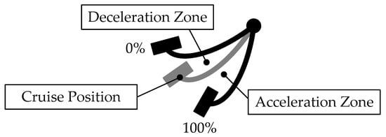
Figure 9.
Diagram of single-pedal control.
For vehicles equipped with a single-pedal braking strategy, the driver’s braking operation is divided into two parts: regenerative braking by lifting the accelerator pedal and composite braking by depressing the brake pedal. Hongwen He et al. [79,80] proposed an adaptive fuzzy control algorithm and a multi-objective optimization neural network controller for these two braking operations and conducted hardware-in-the-loop experiments. The experimental results show that compared with the parallel composite braking strategy, the proposed control method can improve the energy recovery rate and braking stability of electric vehicles.
The throttle map designed in a single-pedal braking system is related to driving comfort. For example, if the throttle map is static and its zero position is fixed, there will be obvious throttle idle travel during the starting of the vehicle, which may cause the driver to panic. J.J.P van Boekel et al. [81] listed the basic requirements of the single-pedal braking strategy, added a speed dimension to the throttle map, and set up a sliding section. Real vehicle tests show that the algorithm can improve driving economy, and the driver’s subjective experience is good. Qin Shi et al. [82] proposed a new dynamic zero-position single-pedal control method, which effectively utilizes the entire pedal stroke. A single-pedal torque controller predicted by a nonlinear model was designed. Experimental results show that compared with dual-pedal control, the proposed control method can reduce energy consumption. In order to be closer to the driving habits of different drivers, vehicles with a single-pedal mode can often adjust the intensity of energy recovery through the human–computer interaction interface. Kyoung Hyun Kwak et al. [83] established a relative distance model when there is a vehicle in front based on the actual driver’s driving habits and based on this, proposed a personalized single-pedal braking algorithm. The simulation experiment showed that the algorithm is close to the actual driver behavior. Based on big data analysis and user surveys, Myung Won Won [84] found that the paddle-type interactive interface with stepped control of energy recovery intensity was not popular and then proposed the idea of a roller-type interactive interface with continuously linearly adjustable energy recovery intensity.
However, the single-pedal braking strategy has inherent disadvantages. When the battery SOC is at a high level, or the battery temperature is extremely low, the battery management system may disable the regenerative braking function or reduce the regenerative braking capability for the purpose of protecting the battery. At this time, under the same accelerator opening position, the regenerative braking force may be different from usual conditions, causing the braking deceleration to be inconsistent with the driver’s expectations, which may cause panic or danger to the driver. In addition, in the single-pedal mode, as the vehicle speed decreases, the regenerative braking force of some models will gradually withdraw, allowing the vehicle to maintain a lower specific speed or coasting speed [78]. This means that at different vehicle speeds, the same accelerator opening of these vehicles will also result in different braking decelerations. However, if the vehicle is equipped with a brake-by-wire system, hydraulic braking can be supplemented when regenerative braking is gradually withdrawn, thereby maintaining a constant braking deceleration.
5.3. Coordinated Composite Braking System
In order to obtain a higher energy recovery rate, regenerative braking should be used whenever possible, and hydraulic braking should be avoided. The decoupling function of the brake-by-wire system makes more efficient energy recovery possible. When the driver depresses the brake pedal, the brake-by-wire system can output no brake pressure or partially output the brake pressure so that the remaining braking demand can be achieved through regenerative braking.
5.3.1. Single-Channel Composite Braking System
The single-channel composite braking strategy refers to only coordinating the master cylinder hydraulic pressure and the motor regenerative braking force during the composite braking process. From the perspective of hydraulic pressure control, there is only one control variable, which is the hydraulic pressure of the master cylinder. The hydraulic pressure of the four wheel-cylinders is always consistent with the hydraulic pressure of the master cylinder, so this method is called a single-channel composite braking strategy. The common single-channel composite braking strategy gives priority to requesting regenerative braking to achieve the braking demands. When the maximum regenerative braking capacity cannot meet the braking demands, hydraulic braking force is then supplemented.
Jens Kolarsky et al. [85] invented a typical regenerative braking control method for a decoupled brake-by-wire system. The system consists of an electronic booster and conventional ESC. When the driver depresses the brake pedal, the electronic booster pushes the brake fluid in its master cylinder into the ESC. At this time, the ESC opens the outlet valves, and the brake fluid pushed by the electronic booster flows into the low-pressure accumulator of the ESC, avoiding the generation of hydraulic braking force in the wheel brakes, thus realizing the decoupling of the brake pedal and hydraulic braking force, while the braking force requirement can be achieved by regenerative braking force. Jian Zhao et al. [86] studied its decoupling control and composite braking control based on this configuration and proposed a composite braking distribution strategy and an actuator coordination control and decoupling strategy. The simulation implementation shows that this strategy can achieve the decoupling of the brake pedal from the wheel-cylinder. Xun Zhao et al. [87] completed the simulation and experiment of a single-channel composite braking strategy based on this configuration, verifying the effectiveness of the system.
During the control process of the single-channel composite braking strategy, the four-wheel wheel-cylinder pressure is always consistent with the master cylinder pressure, and only a single master cylinder pressure needs to be controlled without the participation of the wheel-cylinder pressure adjustment module. Its control method is simple, and the system complexity is low, so it can be widely used in electric vehicles equipped with brake-by-wire systems. However, this strategy also has technical bottlenecks; that is, this method changes the braking force distribution of the original vehicle, making the wheel braking load of the drive shaft too large, and thus, the driven wheels are easy to lock up when the road adhesion coefficient is low, resulting in low braking stability issues of the entire vehicle.
5.3.2. Dual-Channel Composite Braking System
The dual-channel composite braking strategy is based on the single-channel composite braking strategy and uses the feature of One-box EHB that can independently control the wheel-cylinder pressures and thus distinguishes the hydraulic braking forces of the front and rear wheels, thereby adjusting the vehicle’s front and rear braking force distribution in real-time. This dual-channel strategy enables the wheels of the front and rear axles to effectively utilize road adhesion during the composite braking process, thereby ensuring braking stability. Figure 10 shows a brake force distribution comparison between parallel composite braking and coordinated composite braking.
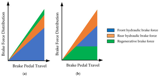
Figure 10.
Brake force distribution comparison between parallel composite braking and coordinated composite braking (a) Parallel composite braking; (b) Coordinated composite braking.
Shunya Watanabe et al. [88] designed a dual-channel composite braking strategy in which the pressure of the front wheels and the rear wheels can be controlled independently. When the front wheels perform regenerative braking, the hydraulic braking force of the rear wheels is supplemented so that the braking forces are distributed close to the ideal braking force distribution, thereby maximizing the braking energy recovery rate while ensuring braking stability.
Junzhi Zhang et al. [89,90,91,92] conducted a lot of research on the regenerative braking control method of a new decoupled brake-by-wire system. The system is hydraulically decoupled through a solenoid valve connected in series between the master cylinder and the hydraulic control unit (HCU). During normal operation, the brake hydraulic pressure is provided by the pressure pumped by the motor in the HCU, and each wheel is equipped with a set of inlet valves and outlet valves to adjust the wheel-cylinder pressures. Taking a front-wheel-drive electric vehicle as an example, when performing composite braking, the braking force distribution is always consistent with the original vehicle. The front axle braking force is primarily provided by regenerative braking force. When the maximum regenerative braking capacity cannot meet the braking demand, it is supplemented by the hydraulic braking force of both front wheels and rear wheels. The braking force of the rear axle is only accomplished by hydraulic braking and is in a fixed proportion to the total braking force of the front axle.
In addition, Junzhi Zhang et al. [93,94,95] proposed a variety of methods for distributing braking force between the front and rear wheels of composite braking for similar mechanical configurations. Generally speaking, the regenerative braking capability is utilized as much as possible while complying with the requirements of ECE regulations. In order to improve braking stability, the braking force distribution is consistent with the ideal distribution curve under high braking intensity.
Theoretically, the dual-channel composite braking strategy can achieve the best braking stability during the composite braking process. However, there are many restrictive factors in practical applications. First of all, the theoretical front and rear braking force distribution curve are affected by the vehicle status and changes in real-time, making it difficult to obtain accurately. Secondly, this method puts forward higher requirements for wheel-cylinder hydraulic pressure control and requires higher pressure control accuracy and response speed. Otherwise, it will cause incoordination between regenerative braking and hydraulic braking, resulting in vehicle deceleration fluctuations. Moreover, if the coordination is carried out according to the theoretical braking force distribution, it is unavoidable to depressurize the wheel-cylinder during the composite braking process. Under the existing technical conditions, pressure-decreasing valves are often high-frequency switching valves with low control accuracy and large noise during the pressure-decreasing process, which is often unacceptable.
5.3.3. Multi-Objective Optimization of Composite Braking Systems
The coordination problem of composition braking control is a multi-objective problem, which requires that during the process of composite braking, the vehicle can ensure strong braking stability, high energy recovery rate, good braking smoothness, etc. At the same time, composite braking control is also a multi-constraint problem, which is restricted by factors such as the external torque characteristics of the drive motor, the efficiency of the drive motor, the response speed of multiple actuators, and the power of the drive battery.
Hongyan Guo et al. [96] took the maximum energy recovery rate, braking safety, and braking force distribution as the control objectives and used the braking response capability and the external characteristics of the drive motor as the limiting conditions to design an upper-layer algorithm for braking force coordination based on MPC. The simulation results show that this control method can maximize the energy recovery rate while ensuring braking safety.
Changran He et al. [97] carried out collaborative optimization with the ideal braking stability and ideal energy recovery rate as the goals, braking stability regulations, motor and battery status, and road adhesion limit as the limiting conditions, and used a deep learning algorithm to analyze the optimization results and then the deep learning control algorithm is obtained. The simulation results show that this method has higher control accuracy than traditional methods and better real-time performance than online optimization.
Tonglie Wu et al. [98] took braking stability and energy recovery rate as optimization objectives and set different weight coefficients for these two targets according to vehicle states such as the current SOC, vehicle speed, and braking intensity, and used genetic optimization algorithms to obtain the composite braking strategy for dual-motor single-axis drive vehicles. The simulation results show that this algorithm can improve the braking energy recovery rate and braking stability.
Jiang Biao et al. [99] took the lowest difference between the four-wheel utilization adhesion coefficient and the braking intensity as the optimization goal and obtained the optimal front and rear braking force distribution under different braking intensities, and on this basis, the drive shaft used as much regenerative brake as possible. The simulation results show that this method improves the energy recovery rate while ensuring braking stability.
5.3.4. Dynamic Coordination of Composite Braking Systems
In the composite braking process, there are two sources of braking force, namely hydraulic braking force and regenerative braking force, and their actuators come from the EHB and the drive motor, respectively. However, the EHB and the drive motor have different principles, and their response speed and control error are also different. The process of coordinating the vehicle braking force between the two sources will affect the braking smoothness of the vehicle. Zhuoping Yu et al. [100] designed a double-closed-loop feedback control strategy for the braking force under transient conditions in view of the characteristics of the drive motor that responds faster than the EHB. They used the regenerative braking force of the drive motor to dynamically compensate for the hydraulic pressure control error of the EHB. HiL experiments show that this strategy significantly increases braking smoothness. Liang Li et al. [101] took into account factors such as the low control accuracy and slow response speed of wire-controlled actuators and designed a transient switching control strategy when ABS is triggered and compensate for the hydraulic braking force through the regenerative braking force of the drive motor. The simulation results show that this method can shorten the braking distance when performing high-intensity braking under different road conditions and shows better braking safety when the brake motor suddenly fails. Kesavan Valis Subramaniyam et al. [102] studied the impact of different regenerative braking exit strategies on vehicle braking performance from the perspectives of vehicle deceleration, pitch angle, suspension deformation, slip rate, and braking distance. The simulation experiments concluded that the slope descent exit strategy can reduce transient changes, thus improving the vehicle braking performance.
Table 6 shows the summary of coordinated composite braking.
Table 6.
Summary of coordinated composite braking.
6. Conclusions
As the current development trend of hydraulic braking systems, One-box EHB has many advantages, such as low cost, high integration, and the ability to achieve complete decoupling. At the same time, the new structure also brings new challenges, and researchers have conducted in-depth research on topics such as design, control, and application. The following conclusions summarize these studies and propose future research prospects.
6.1. System Architecture Design
In terms of system architecture design, the research on a single One-box EHB system has been relatively complete, which can meet the new requirements for automotive braking systems under the development of ITS and automobile electrification. It has complete functions, and each solution has appropriate identification and processing mechanisms for typical single-point failure modes of braking systems and can ensure the failure backup of the automotive braking system.
However, due to the higher redundancy requirements of high-level autonomous driving on active braking functions, there is still few literature and research on related system architectures, which restricts the development of intelligent vehicles from level L2 to L3 and even higher levels. System architectures suitable for high-level autonomous vehicles should be further studied.
6.2. Master Cylinder Pressure Control
Regarding the master cylinder pressure control, since the mechanical structures of the pressure-building units of One-box EHB and Two-box EHB are relatively similar, the master cylinder pressure control of One-box EHB can basically follow or refer to the control method under the Two-box EHB architecture. Its development is relatively mature, and researchers have conducted a large number of studies on issues such as internal friction, robust control, and pressure estimation.
However, during the process of regulating wheel-cylinder pressures, the master cylinder pressure control provides the back pressure. At this time, the master cylinder pressure control quality will directly affect the wheel-cylinder pressure control quality. During the process of wheel-cylinder pressure regulation, the parameters of the braking system will change significantly, which will have a serious impact on the piston position control, speed control, etc., within the master cylinder pressure control. Regarding the master cylinder pressure control during the dynamic regulation process of wheel-cylinder pressures, the current research is not in-depth enough, and further research is needed.
6.3. Wheel-Cylinder Pressure Control
For wheel-cylinder pressure control, the key lies in the understanding and control of the solenoid valves. Its basic principle is similar to that of the traditional ESC solenoid valves. Researchers have carried out a lot of research on this issue, including high-frequency switching control, critical differential pressure control, flow control, valve spool position control, etc.
However, the hydraulic layout in the One-box EHB system architecture is different from the traditional ESC. In the process of dynamic control of the four wheel-cylinder pressures, the coordinated control of the four wheel-cylinder pressures is also different from the single-valve control in the ESC. There are few relevant studies on this topic. At the same time, One-box EHB has derived new types of solenoid valves. These solenoid valves have different functions and different performance requirements. The research on the design methodologies of these new solenoid valves is currently confidential to each company, and there is little public literature.
6.4. Electro-Hydraulic Composite Braking Control
Electro-hydraulic composite braking has attracted the attention of researchers as an effective means to extend the driving range of electric vehicles. With the emergence of new brake-by-wire systems with decoupling capabilities, coordinated composite braking technology has improved the vehicle’s regenerative braking capabilities, and researchers have also conducted in-depth research on this.
However, some of these studies were divorced from actual brake actuators and only designed composite brake control strategies from a theoretical level without actual experimental verifications. Since a coordinated composite braking strategy deeply depends on the characteristics and capability boundaries of the brake actuators and their decoupling components, designing an appropriate composite braking strategy based on the system characteristics of One-box EHB and meet the needs of the electric vehicles is an important topic that needs further research.
Author Contributions
Conceptualization, X.Z. (Xinyu Zhao), Q.S. and G.Z.; writing—original draft preparation, X.Z. (Xinyu Zhao), J.L., X.Z. (Xuanbai Zhao) and G.X.; writing—review and editing, G.Z. and W.T.; visualization, X.Z. (Xuanbai Zhao), J.L., X.Z. (Xinyu Zhao) and G.X.; supervision, G.Z. and L.X.; funding acquisition, L.X. All authors have read and agreed to the published version of the manuscript.
Funding
This research was funded by the National Natural Science Foundation of China under Grant 52325212, Shanghai Science and Technology Innovation Action Plan (No. 23XD1434000), the Fundamental Research Funds for the Central Universities, and the Program of Shanghai Automotive Industry Science and Technology Development Foundation (No. 1839).
Institutional Review Board Statement
Not applicable.
Informed Consent Statement
Not applicable.
Data Availability Statement
Data are contained within the article.
Conflicts of Interest
The authors declare no conflicts of interest. Author Qiang Shu, Xuanbai Zhao and Guodong Xu were employed by the company Shanghai Tongyu Automotive Technology Co., Ltd. The remaining authors declare that the research was conducted in the absence of any commercial or financial relationships that could be construed as a potential conflict of interest.
References
- Deng, X.; Wang, L.; Gui, J.; Jiang, P.; Chen, X.; Zeng, F.; Wan, S. A review of 6G autonomous intelligent transportation systems: Mechanisms, applications and challenges. J. Syst. Archit. 2023, 142, 102929. [Google Scholar] [CrossRef]
- Tyagi, A.K.; Sreenath, N. Intelligent transportation system: Past, present, and future. In Intelligent Transportation Systems: Theory and Practice; Prasenjit, C., Anjali, A., Eds.; Springer: Singapore, 2023; pp. 23–47. [Google Scholar]
- Zhang, Y.; Yao, D.-Y.; Li, L.; Pei, H.; Yan, S.; Ge, J. Technologies and Applications for Intelligent Vehicle-infrastructure Cooperation Systems. J. Transp. Syst. Eng. Inf. Technol. 2021, 21, 40. [Google Scholar]
- Wang, P.; Bai, S.; Wang, Y.; Liu, W.; Li, M.E. Research on Generational Evolution of Autonomous Transportation System in Autonomous Driving Scenario. In Proceedings of the 22nd COTA International Conference of Transportation Professionals, Changsha, China, 8–11 July 2022. [Google Scholar]
- Carrese, F.; Sportiello, S.; Zhaksylykov, T.; Colombaroni, C.; Carrese, S.; Papaveri, M.; Patella, S.M. The Integration of Shared Autonomous Vehicles in Public Transportation Services: A Systematic Review. Sustainability 2023, 15, 13023. [Google Scholar] [CrossRef]
- ESP® hev. Available online: https://www.bosch-mobility.com/en/solutions/driving-safety/esp-hev-module/ (accessed on 23 November 2023).
- Kohl, A.; Wichenhofer, T. Method for Operating a Braking System and Braking System. US Patent US20200001846A1, 2 January 2020. [Google Scholar]
- Wagner, J.; Kranich, M.; Taubitz, N.; Collins, R.; Zahariev, S.; Strehle, A. Robert Bosch GmbH. Method for Controlling an Electronically Slip-controllable Power Braking System. US Patent US20190359191A1, 28 November 2019. [Google Scholar]
- Yu, W.; Hawley, S. Method of Controlling a Vehicle Brake System. US Patent US20200070793A1, 5 March 2020. [Google Scholar]
- Kim, J. Electronic Brake System. US Patent US20230174037A1, 8 June 2023. [Google Scholar]
- Kim, J.; Seongho, C. Electronic Brake System and Operating Method Thereof. WO Patent WO 2022146053A1, 7 July 2022. [Google Scholar]
- Yong, C.S.; Jee, S.L.; Wan, K.J. Apparatus and Method for Controlling ESC-Integrated Regenerative Braking System. US Patent US11597368B2, 7 March 2023. [Google Scholar]
- United Nations. Uniform Provisions Concerning the Approval of Passenger Cars with Regard to Braking. UN Regulation No. 13-H. Available online: https://unece.org/transport/vehicle-regulations-wp29/standards/addenda-1958-agreement-regulations-0-20 (accessed on 23 November 2023).
- Park, Y. Electric Brake System and Control Method Thereof. US Patent US11084473B2, 10 August 2021. [Google Scholar]
- Briesewitz, R.; Dolmaya, J. Brake-by-wire Braking System Having at least One Brake Circuit, Method for Operating the Braking System and Diagnosis Valve for a Braking System of This Type. US Patent US20210300314A1, 30 September 2021. [Google Scholar]
- Biller, H. Brake System for Motor Vehicles and Method for Operating a Brake System. US Patent US11639164B2, 2 May 2023. [Google Scholar]
- Brenn, M.; Ullrich, T. Method for Operating a Braking System, and Braking System. US Patent US20220073048A1, 10 March 2022. [Google Scholar]
- Reuter, D.F.; Luo, D. Electro-Hydraulic Brake System. EP Patent EP4001033B1, 18 November 2021. [Google Scholar]
- Jeong, H. Electric Brake System and Operating Method Thereof. US Patent US10857988B2, 8 December 2020. [Google Scholar]
- Yong, C.S. Apparatus for Controlling Anti Lock Brake System of ESC Integrated Brake System and Method Thereof. US Patent US 11752990B2, 12 September 2023. [Google Scholar]
- Courth, C.; Seidel, A.; Lohse, U.; Neu, A.; Caspari, R. Continental Teves AG and Co oHG. Method for Monitoring a Hydraulic Brake System for a Motor Vehicle and Brake System. US Patent US20210245725A1, 12 August 2021. [Google Scholar]
- Henning, W. Method and Control Unit for Operating a Braking System and Braking System. US Patent US11230276B2, 25 January 2022. [Google Scholar]
- SAE International. Taxonomy and Definitions for Terms Related to Driving Automation Systems for On-Road Motor Vehicles. SAE J3016, April 2021. Available online: https://www.sae.org/standards/content/j3016_202104/ (accessed on 11 December 2023).
- Bauer, U.; Brand, M.; Maucher, T. Integrated Power Brake—Modular Set Extension for Highly Automated Driving. In 8th International Munich Chassis Symposium 2017; Springer: Wiesbaden, Germany, 2017. [Google Scholar]
- Bareiss, A.; Reiner, J.; Zander, T. Electro-Hydraulic Power Vehicle-Brake System for an Autonomous Driving Land Vehicle. US Patent US20190344767A1, 14 November 2019. [Google Scholar]
- Zipfel, T.; Nakayasu, Y.; Rizzo, J. Brake Architecture for Automated Driving. US Patent US20170341630A1, 30 November 2017. [Google Scholar]
- Tarandek, K.; Feigel, H.J.; Kurbasa, J.; Bouzid, R.; Leiter, R.; Jeong, H.J.; Jung, H.C. Electronic Brake System and Control Method Thereof. US Patent US20220194339A1, 23 January 2022. [Google Scholar]
- Campau, G.P. Vehicle Brake System with Auxiliary Control Unit. US Patent US20200216052A1, 8 July 2020. [Google Scholar]
- Hong, K. Electronic Brake System and Control Method Therefor. US Patent US20230029756A1, 2 February 2023. [Google Scholar]
- Kim, M.; Kim, S.W.; Han, S. Control Device Structure of Brake System. US Patent US20220340112A1, 27 October 2022. [Google Scholar]
- Yang, I.-J.; Choi, K.; Huh, K. Development of an Electric Booster System Using Sliding Mode Control for Improved Braking System. Int. J. Automot. Technol. 2012, 13, 1005–1011. [Google Scholar] [CrossRef]
- Todeschini, F.; Corno, M.; Panzani, G.; Savaresi, S.M. Adaptive position–pressure control of a brake by wire actuator for sport motorcycles. Eur. J. Control 2014, 20, 79–86. [Google Scholar] [CrossRef]
- Wang, Z.; Yu, L.; Wang, Y.; You, C.; Ma, L.; Song, J. Prototype of Distributed Electro-Hydraulic Braking System and its Fail-Safe Control Strategy. SAE Technical Paper 2013-01-2066. 2013. Available online: https://www.sae.org/publications/technical-papers/content/2013-01-2066/ (accessed on 11 December 2023).
- Chen, L.; Yu, Y.; Luo, J. Master Cylinder Oil Pressure Following Control Algorithm of Electric Power Assisted Braking System Based on Fuzzy PID Controller. In Proceedings of the 2022 4th International Conference on Artificial Intelligence and Advanced Manufacturing (AIAM), Hamburg, Germany, 7–9 October 2022. [Google Scholar]
- Zhao, J.; Hu, Z.; Zhu, B. Pressure Control for Hydraulic Brake System Equipped with an Electro-Mechanical Brake Booster. SAE Technical Paper 2018-01-0329. 2018. Available online: https://www.sae.org/publications/technical-papers/content/2018-01-0829/ (accessed on 11 December 2023).
- Yang, W.; Wu, J.; He, R.; Zhu, B.; Zhao, J.; Chen, Z. Pressure Tracking Control of Electro-Mechanical Brake Booster System. SAE SAE Technical Paper 2020-01-0211. 2020. Available online: https://www.sae.org/publications/technical-papers/content/2020-01-0211/ (accessed on 11 December 2023).
- Zhao, J.; Chen, Z.; Zhu, B.; Wu, J. Precise Active Brake-Pressure Control for a Novel Electro-Booster Brake System. IEEE Trans. Ind. Electron. 2020, 67, 6. [Google Scholar] [CrossRef]
- Wang, J.; Wu, J.; He, R.; Chen, Z. Pressure Optimization Control of Electro-Mechanical Brake System in the Process of ABS Working. SAE SAE Technical Paper 2019-01-1104. 2019. Available online: https://www.sae.org/publications/technical-papers/content/2019-01-1104/ (accessed on 11 December 2023).
- Wang, B.; Wang, M.; Jiang, Y.; Shangguan, W.B. A Research on Modeling and Pressure Control of Integrated Electro-Hydraulic Brake System. SAE SAE Technical Paper 2021-01-0130. 2021. Available online: https://www.sae.org/publications/technical-papers/content/2021-01-0130/ (accessed on 11 December 2023).
- De Castro, R.; Todeschini, F.; Araujo, R.E.; Savaresi, S.M.; Corno, M.; Freitas, D. Adaptive-robust friction compensation in a hybrid brake-by-wire actuator. Proc. IMechE Part I J. Syst. Control Eng. 2014, 228, 769–786. [Google Scholar] [CrossRef]
- Ji, Y.; Zhang, J.; He, C.; Ma, R.; Hou, X.; Hu, H. Constraint performance pressure tracking control with asymmetric continuous friction compensation for booster based brake-by-wire system. Mech. Syst. Signal Process. 2022, 174, 109083. [Google Scholar] [CrossRef]
- Wei, H.; Lu, X.; Zhuoping, Y. A novel pressure control strategy of an electro-hydraulic brake system via fusion of control signals. Proc. IMechE Part D J. Automob. Eng. 2019, 233, 3342–3357. [Google Scholar]
- Chen, Z.; Huang, C.; Liu, Z.; Liu, Y.; Wang, X.; Shi, B.; Li, L. An Offset-Free Explicit Model Predictive Pressure Controller for Integrated Braking System. IEEE Trans. Transp. Electrif. 2023, 3298001. [Google Scholar] [CrossRef]
- Yu, Z.; Xu, S.; Xiong, L.; Guang, X. Robustness Hydraulic Pressure Control System of Integrated-electro-hydraulic Brake System. J. Mech. Eng. 2015, 51, 16. [Google Scholar] [CrossRef]
- Shangguan, W.-B.; Liang, T.-Q.; Jiang, K.-H. Modeling and Pressure Control of Integrated Electro-Hydraulic Brake System. Trans. Beijing Inst. Technol. 2019, 39, 4. [Google Scholar]
- Todeschini, F.; Corno, M.; Panzani, G.; Fiorenti, S.; Savaresi, S.M. Adaptive Cascade Control of a Brake-By-Wire Actuator for Sport Motorcycles. IEEE/ASME Trans. Mechatron. 2015, 20, 3. [Google Scholar] [CrossRef]
- Todeshini, F.; Fornentin, S.; Panzani, G.; Corno, M.; Sacaresi, S.M.; Zaccarian, L. Nonlinear Pressure Control for BBW Systems via Dead-Zone and Antiwindup Compensation. IEEE Trans. Control. Syst. Technol. 2016, 24, 4. [Google Scholar] [CrossRef]
- Wu, J.; Chen, P.; Zhao, J.; He, R. Active Braking of an Electronic Brake Booster Facing Intelligent Automobile. Int. J. Perform. Eng. 2018, 14, 8. [Google Scholar] [CrossRef]
- Chen, Z.; Zhu, B.; Zhao, J.; Wu, J. Multi-closed-loop Pressure Control Strategy Considering Nonlinear Characteristics of Electro-booster Brake System. J. Mech. Eng. 2023, 59, 4. [Google Scholar]
- Zhu, B.; Zhang, Y.-H.; Zhao, J. Precise Control Method for Active Brake Pressure Based on an Integrated Braking Control System. China J. Highw. Transp. 2021, 34, 9. [Google Scholar]
- Jiang, L.; Shi, Q.; Wei, Y.; He, Y.; He, Z.; He, L. Electro-hydraulic braking dynamics for pressure demand control of brake-by-wire system. Proc. IMechE Part D J. Automob. Eng. 2022, 1–14. [Google Scholar] [CrossRef]
- Zhao, J.; Deng, Z.; Zhu, B.; Chang, T.; Chen, Z. Sliding Mode Control Based on RBF Network for Hydraulic Pressure in Electric Power-assisted Brake System. J. Mech. Eng. 2020, 56, 24. [Google Scholar]
- Han, W.; Xiong, L.; Yu, Z. Braking pressure control in electro-hydraulic brake system based on pressure estimation with nonlinearities and uncertainties. Mech. Syst. Signal Process. 2019, 131, 703–727. [Google Scholar] [CrossRef]
- Han, W.; Xiong, L.; Yu, Z.; Zhuo, G.; Leng, B.; Xu, S. Integrated Pressure Estimation and Control for Electro-hydraulic Brake Systems of Electric Vehicles Considering Actuator Characteristics and Vehicle Longitudinal Dynamics. IEEE/ASME Trans. Mechatron. 2023, 28, 1. [Google Scholar] [CrossRef]
- Shi, B.; Xiong, L.; Yu, Z. Pressure Estimation Based on Vehicle Dynamics Considering the Evolution of the Brake Linings’ Coefficient of Friction. Actuators 2021, 10, 76. [Google Scholar] [CrossRef]
- Gao, X.; Yang, Y.; Zhao, X.; Li, C. Non-linear dynamic modelling of a switching valve driven by pulse width modulation in the hydraulic braking system of a vehicle. Proc. IMechE Part D J. Automob. Eng. 2017, 231, 1511–1529. [Google Scholar] [CrossRef]
- Meng, A.; Garris, C.; Wei, L.; Liu, H. Visual System Analysis of High Speed On-Off Valve Based on Multi-Physics Simulation. SAE Technical Paper 2022-01-0391. 2022. Available online: https://www.sae.org/publications/technical-papers/content/2022-01-0391/ (accessed on 11 December 2023).
- Sorniotti, A.; Velardocchia, M. Hardware-In-the-Loop (HIL) Testing of ESP (Electronic Stability Program) Commercial Hydraulic Units and Implementation of New Control Strategies. SAE Technical Paper 2004-01-2770. 2004. Available online: https://www.sae.org/publications/technical-papers/content/2004-01-2770/ (accessed on 11 December 2023).
- O’Dea, K. Anti-Lock Braking Performance and Hydraulic Brake Pressure Estimation. SAE Technical Paper 2005-01-1061. 2005. Available online: https://www.sae.org/publications/technical-papers/content/2005-01-1061/ (accessed on 11 December 2023).
- Ding, N.; Pan, W.; Fang, Y. Measurement of Hydraulic Pressure Response for ABS and Fine Regulation of Pressure. Chin. J. Mech. Eng. 2004, 40, 6. [Google Scholar] [CrossRef]
- Chen, Z.; Wu, J.; Zhu, B. Accurate Pressure Control Strategy of Electronic Stability Program Based on the Building Characteristics of High-Speed Switching Valve. SAE Technical Paper 2019-01-1107. 2019. Available online: https://www.sae.org/publications/technical-papers/content/2019-01-1107/ (accessed on 11 December 2023).
- Zhang, J.; Lv, C.; Yue, X.; Li, Y.; Yuan, Y. Study on a linear relationship between limited pressure difference and coil current of on/off valve and its influential factors. ISA Trans. 2014, 53, 150–161. [Google Scholar] [CrossRef] [PubMed]
- Lv, C.; Zhang, J.; Li, Y.; Sun, D.; Yuan, Y. Hardware-in-the-loop simulation of pressure-difference-limiting modulation of the hydraulic brake for regenerative braking control of electric vehicles. Proc. IMechE Part D J. Automob. Eng. 2014, 228, 649–662. [Google Scholar] [CrossRef]
- Jing, H.; Dong, L.; Feng, R. Active Pressure Control and Experimental Application Based on Automotive Hydraulic Control Unit. In Proceedings of the 41st Chinese Control Conference, Hefei, China, 25–27 July 2022. [Google Scholar]
- Lv, C.; Wang, H.; Cao, D. High-Precision Hydraulic Pressure Control Based on Linear Pressure-Drop Modulation in Valve Critical Equilibrium State. IEEE Trans. Ind. Electron. 2017, 64, 10. [Google Scholar] [CrossRef]
- Wang, W.; Song, J.; Li, L.; Li, H. High speed on-off solenoid valve with proportional control based on high frequency PWM control. J. Tsinghua Univ. (Sci. Tech.) 2011, 5, 5. [Google Scholar]
- Zhao, X.; Li, L.; Song, J.; Li, C.; Gao, X. Linear Control of Switching Valve in Vehicle Hydraulic Control Unit Based on Sensorless Solenoid Position Estimation. IEEE Trans. Ind. Electron. 2016, 63, 7. [Google Scholar] [CrossRef]
- Zhao, X.; Xu, W.-B.; Liu, G. Pressure Estimation and Pressure Control of Hydraulic Control Unit in Electric-Wheel Vehicle. Math. Probl. Eng. 2020, 2020, 6576297. [Google Scholar]
- Zhang, Q.; Jin, L.; Zhang, Y.; Li, J. Research on Estimation and Precise Control of Wheel Cylinder Pressure for Integrated Electronic Hydraulic Brake System. In Proceedings of the 2021 China Automation Congress (CAC), Beijing, China, 22–24 October 2021. [Google Scholar]
- Jiang, G.; Miao, X.; Wang, Y.; Chen, J.; Li, D.; Liu, L.; Muhammad, F. Real-time estimation of the pressure in the wheel cylinder with a hydraulic control unit in the vehicle braking control system based on the extended Kalman filter. Proc. IMechE Part D J. Automob. Eng. 2017, 231, 1340–1352. [Google Scholar] [CrossRef]
- Liu, H.; Wei, L.; Liu, H.; Wu, J.; Wang, X. EKF-Based Wheel Cylinder Pressure Estimation of Integrated Braking System. In Proceedings of the 2022 IEEE 25th International Conference on Intelligent Transportation Systems (ITSC), Macau, China, 8–12 October 2022. [Google Scholar]
- Wei, L.; Wang, X.; Li, L. Wheel Pressure Estimation of Hydraulic Integrated Braking System by Fusion Model. In Proceedings of the 2023 9th International Conference on Control, Automation and Robotics, Beijing, China, 21–23 April 2023. [Google Scholar]
- Zhang, J.; Li, L.; Jiang, H.; Liu, Q.; Wang, Y.; Yuan, W.; Wu, J.; Zhang, X.; Chen, Z. Active Brake Wheel Cylinder Pressure Control Based On Integrated Electro-Hydraulic Brake System; SAE Technical Paper 2022-01-0293. 2022. Available online: https://www.sae.org/publications/technical-papers/content/2022-01-0293/ (accessed on 11 December 2023).
- Han, W.; Xiong, L.; Yu, Z. Analysis and Optimization of Minimum Hydraulic Brake-by-Wire System for Wheeled Vehicles Based on Queueing Theory. IEEE Trans. Veh. Technol. 2021, 70, 12. [Google Scholar] [CrossRef]
- Liu, H.; He, R.; Deng, W.; Yang, S.; Wu, J.; Chen, P. Research on a Novel Electro-Hydraulic Brake System and Pressure Control Strategy. SAE Technical Paper 2018-01-0764. 2018. Available online: https://www.sae.org/publications/technical-papers/content/2018-01-0764/ (accessed on 11 December 2023).
- Ji, Y.; Zhang, J.; He, C.; Hou, X.; Liu, W.; Han, J. Wheel Braking Pressure Control Based on Central Booster Electrohydraulic Brake-by-Wire System. IEEE Trans. Transp. Electrif. 2023, 9, 1. [Google Scholar] [CrossRef]
- Siddiqui, O.; Simacek, D.; Hoang, R.; Famiglietti, N.; Nguyen, B.; Landerville, J. Characterizing Regenerative Coast-Down Deceleration in Tesla Model 3, S, and X. SAE Technical Paper 2020-01-0883. 2020. Available online: https://www.sae.org/publications/technical-papers/content/2020-01-0883/ (accessed on 11 December 2023).
- Vigil, C.M.; Kaayal, O.; Szepelak, A. Quantifying the Deceleration of Various Electric Vehicles Utilizing Regenerative Braking. SAE Technical Paper 2023-01-0623. 2023. Available online: https://www.sae.org/publications/technical-papers/content/2023-01-0623/ (accessed on 11 December 2023).
- He, H.; Wang, C.; Jia, H.; Cui, X. An intelligent braking system composed single-pedal and multi-objective optimization neural network braking control strategies for electric vehicle. Appl. Energy 2020, 259, 114172. [Google Scholar] [CrossRef]
- He, H.; Wang, C.; Jia, H. A single-pedal regenerative braking control strategy of accelerator pedal for electric vehicles based on adaptive fuzzy control algorithm. In Proceedings of the CUE2018-Applied Energy Symposium and Forum 2018: Low Carbon Cities and Unban Energy Systems, Shanghai, China, 5–7 June 2018. [Google Scholar]
- Van Boekel, J.J.; Besselink, I.J.; Nijmeijer, H. Design and realization of a One-Pedal-Driving algorithm for the TU/e Lupo EL. In Proceedings of the EVS28, Goyang, Republic of Korea, 3–6 May 2015. [Google Scholar]
- Shi, Q.; He, Z.; Wei, Y.; Wang, M.; Zheng, X.; He, L. Single Pedal Control of Battery Electric Vehicle by Pedal Torque Demand With Dynamic Zero Position. IEEE Trans. Intell. Transp. Syst. 2022, 23, 11. [Google Scholar] [CrossRef]
- Kwak, K.H.; He, Y.; Kim, Y.; Chen, Y.M.; Fan, S.; Holmer, J.; Lee, J.H. Desired Relative Distance Model-based Personalized Braking Algorithm for One-pedal Driving of Electric Vehicles. IFAC 2022, 55, 62–67. [Google Scholar] [CrossRef]
- Won, M.W. A Study on the Improvement of EV One-Pedal Driving System Interface and Cost Reduction. SAE Technical Paper 2022-01-0645. 2022. Available online: https://www.sae.org/publications/technical-papers/content/2022-01-0645/ (accessed on 11 December 2023).
- Kolarsky, J.; Kunz, M.; Strengert, S.; Vollert, H. Method for Operating a Regenerative Brake System of a Vehicle, Control Device for a Regenerative Brake System of a Vehicle, and Regenerative Brake System. US Patent US9827965B2, 28 November 2017. [Google Scholar]
- Zhao, J.; Hu, Z.; Zhu, B. Regenerative Braking Pedal Decoupling Control for Hydraulic Brake System Equipped with an Electro-Mechanical Brake Booster. SAE Technical Paper 2019-01-1108. 2019. Available online: https://www.sae.org/publications/technical-papers/content/2019-01-1108/ (accessed on 11 December 2023).
- Zhao, X.; Li, L.; Wang, X.; Mei, M.; Liu, C.; Song, J. Braking force decoupling control without pressure sensor for a novel series regenerative brake system. Proc. IMechE Part D J. Automob. Eng. 2019, 233, 1750–1766. [Google Scholar] [CrossRef]
- Watanabe, S.; Yamamoto, T.; Masuda, Y.; Yamakita, H. Electronically Controlled Brake System with Two-Channel Pressure Control for Electric Vehicles; SAE Technical Paper 2023-01-0663. 2023. Available online: https://www.sae.org/publications/technical-papers/content/2023-01-0663/ (accessed on 11 December 2023).
- Yuan, Y.; Zhang, J.; Lv, C.; Li, Y. Design and Performance Analysis of a Novel Regenerative Braking System for Electrified Passenger Vehicles. SAE Technical Paper 2016-01-0438. 2016. Available online: https://www.sae.org/publications/technical-papers/content/2016-01-0438/ (accessed on 11 December 2023).
- Yuan, Y.; Zhang, J.; Li, Y.; Lv, C. Regenerative Brake-by-Wire System Development and Hardware-in-Loop Test for Autonomous Electrified Vehicle. SAE Technical Paper 2017-01-0401. 2017. Available online: https://www.sae.org/publications/technical-papers/content/2017-01-0401/ (accessed on 11 December 2023).
- Yuan, Y.; Zhang, J.; Li, Y.; Li, C. A Novel Regenerative Electrohydraulic Brake System: Development and Hardware-in-Loop Tests. IEEE Trans. Veh. Technol. 2018, 67, 12. [Google Scholar] [CrossRef]
- Li, C.; He, C.; Yuan, Y.; Zhang, J. Co-simulation on Performance Evaluation of a New Electronic Control Hydraulic Braking System. In Proceedings of the IAEAC 2018, Chongqing, China, 12–14 October 2018. [Google Scholar]
- Lv, C.; Zhang, J.; Li, Y.; Yuan, Y. Regenerative Braking Control Algorithm for an Electrified Vehicle Equipped with a By-Wire Brake System. SAE Technical Paper 2014-01-1791. 2014. Available online: https://www.sae.org/publications/technical-papers/content/2014-01-1791/ (accessed on 11 December 2023).
- Hou, X.; Zhang, J.; Zhang, Z.; He, C. Analysis of Active Collision Avoidance Performance Based on Cooperative Regenerative Auxiliary Braking System. SAE Technical Paper 2019-01-5027. 2019. Available online: https://www.sae.org/publications/technical-papers/content/2019-01-5027/ (accessed on 11 December 2023).
- Li, C.; He, C.; Yuan, Y.; Zhang, J. Braking Evaluation of Integrated Electronic Hydraulic Brake System Equipped in Electric Vehicle. In Proceedings of the ITNEC 2019, Chengdu, China, 15–17 March 2019. [Google Scholar]
- Guo, H.; Zhao, X.; Liu, J.; Zhu, F.; Chen, H.; Cao, D. Hierarchical coordinated control strategy for regenerative braking energy recuperation with an electrobooster. Proc. IMechE Part D J. Automob. Eng. 2022, 1–14. [Google Scholar] [CrossRef]
- He, C.; Wang, G.; Gong, Z.; Xing, Z.; Xu, D. A Control Algorithm for the Novel Regenerative–Mechanical Coupled Brake System with by-Wire Based on Multidisciplinary Design Optimization for an Electric Vehicle. Energies 2018, 11, 2322. [Google Scholar] [CrossRef]
- Wu, T.; Wang, F.; Ye, P. Regenerative Braking Strategy of Dual-Motor EV Considering Energy Recovery and Brake Stability. World Electr. Veh. J. 2023, 14, 19. [Google Scholar] [CrossRef]
- Jiang, B.; Zhang, X.; Wang, Y.; Hu, W. Regenerative braking control strategy of electric vehicles based on braking stability requirements. Int. J. Automot. Technol. 2021, 22, 465–473. [Google Scholar]
- Yu, Z.; Shi, B.; Xiong, L.; Han, W. Coordinated Control under Transitional Conditions in Hybrid Braking of Electric Vehicle. SAE Technical Paper 2018-01-1869. 2018. Available online: https://www.sae.org/publications/technical-papers/content/2018-01-1869/ (accessed on 11 December 2023).
- Li, X.; Li, X.; Wang, X.; Liu, Y.; Song, J.; Ran, X. Transient switching control strategy from regenerative braking to anti-lock braking with a semi-brake-by-wire system. Veh. Syst. Dyn. 2016, 54, 231–257. [Google Scholar] [CrossRef]
- Subramaniyam, K.V.; Subramanian, S.C. Impact of regenerative braking torque blend-out characteristics on electrified heavy road vehicle braking performance. Veh. Syst. Dyn. 2021, 59, 269–294. [Google Scholar] [CrossRef]


Disclaimer/Publisher’s Note: The statements, opinions and data contained in all publications are solely those of the individual author(s) and contributor(s) and not of MDPI and/or the editor(s). MDPI and/or the editor(s) disclaim responsibility for any injury to people or property resulting from any ideas, methods, instructions or products referred to in the content. |
© 2024 by the authors. Licensee MDPI, Basel, Switzerland. This article is an open access article distributed under the terms and conditions of the Creative Commons Attribution (CC BY) license (https://creativecommons.org/licenses/by/4.0/).