1. Introduction
Production processes are subject to continuous improvement, which on the one hand aims to increase efficiency and, on the other hand, ensure the appropriate quality of products. The achievability of this goal depends largely on the use of advanced robotic and automated production systems. All this makes industrial robotics one of the fastest growing sectors of the economy [
1], but it is also subject to constant research in very different fields [
2]. This approach has been widely used so far, but is now considered insufficient due to drastic climate changes. The boundless pursuit of increasing production profits without looking at the broader perspective of the global climate leads to the degradation of the natural environment. The existing concepts of Industry 4.0 have therefore been revised and supplemented in the assumptions of Industry 5.0. In addition to robotic production processes and intelligent machines to increase production efficiency, the focus is on the cooperation of these devices with humans and on sustainable development [
3].
Robotic welding is considered the most popular use of robots in industry on a global scale [
4]. The reason for the popularity of robotic welding is the nature of welding tasks, which often require repeatable, precise movements, constituting an ideal area of application of robots [
5]. Moreover, welding robots reduce production time and costs, improve the quality of welds and increase the efficiency and reliability of the welding process [
6]. The importance and popularity of robotic welding is a particularly important area from the point of view of introducing sustainable changes and energy efficiency. Improving this area of industry can make a significant contribution to environmental transformation.
Industrial welding robots have become an integral part of manufacturing processes, providing precision, efficiency, and reliability in welding tasks across a wide range of applications. Their key work features include precision and consistency, high-speed operation (can operate at a higher speed than manual welding, significantly increasing production rates), flexibility, improved quality, and safety.
The motion of welding robots during the welding of parts is determined by sophisticated algorithms that ensure optimal path planning, speed, and welding parameters [
7]. These algorithms can include the following:
- −
Path planning algorithms, which determine the most efficient path the robot arm should follow to complete the welding task, taking into account the geometry of the parts to be welded;
- −
Seam tracking, where advanced vision or sensor-based systems allow the robot to detect and follow the welding seam in real-time, adjusting the path as needed to accommodate variations in the seam;
- −
Speed and other parameter control, which allow the adjustment of the welding speed, power, and other parameters dynamically to ensure consistent weld quality across different parts of the workpiece.
Industrial welding robots offer a compelling array of benefits, particularly for high-volume, repetitive welding tasks where precision and consistency are paramount. However, the high initial investment, limited flexibility, and the need for skilled maintenance and programming are significant considerations. As technology advances, it can be expected that these robots will become more versatile, easier to program, and even more integrated into manufacturing processes.
Three-dimensional modeling and simulation and offline robot programming software are critical in optimizing welding operations, allowing manufacturers to increase efficiency, reduce production times, and improve weld quality by meticulously planning and simulating welding processes before real implementation into production. Offline programming is an intuitive and automatic generation technique that does not use real robotic systems. Currently, this type of programming can be generally categorized into computer-aided-design-based and vision-based approaches which have been widely applied in robotic welding systems [
8]. These tools enable the detailed programming of robotic welding operations without interrupting the production line, ensuring that the actual welding process is both time- and cost-efficient. RobotStudio 2022 software is dedicated to simulating the welding process for ABB robots, and it can most fully and precisely reflect the actual situation related to the presented process taking place on this manufacturer’s robots.
Analysis of the energy consumption of industrial robots, including the design of energy-saving solutions, is facilitated by simulation software and offline programming [
9]. Many simulation programs have add-ons that allow you to indicate the energy values generated by the developed production process along with time analysis. This is a tool for optimizing process efficiency and sustainable energy use [
10]. Designed robotic welding processes and offline programmed robots, after verifying the design assumptions, can be implemented in real conditions by transmitting data to the robot controller [
11]. Therefore, offline programming contributes to increasing the precision and efficiency of welding processes [
12], reduces process downtime [
13], improves the profitability of process energy optimization [
14], improves safety [
15], and also affects the flexibility and adaptability of robotic systems [
16].
From the point of view of sustainable development, optimizing robotic welding processes means taking into account not only economic and technical criteria, but primarily focusing on the balance between economic growth, environmental protection and social equality [
17]. Environmental sustainability includes reducing the energy consumption of an industrial robot implementing a technological process. For this purpose, it is possible to optimize the robot’s movement trajectory and its operating parameters, minimize production waste, and recycle it. Optimizing the robot’s operation also increases its service life and reduces the frequency of repairs and replacement of parts as well as the robot itself [
18]. Social sustainability includes improving occupational safety. From the point of view of the robotic process, the operation of the robot that minimizes the risk of employee accidents but also increases ergonomics and comfort in the workplace is taken into account. When welding robots are used, human work focuses on programming the robot to perform specific tasks and supervising this process [
19].
Robotization of technological processes in the context of sustainable development is increasingly discussed in current research publications. Gadaleta et al. presented a method to automatically compute the energy-optimal motion parameters of an industrial robot. The benefits of this approach are reducing the robot energy consumption and keeping the same level of manufacturing quality. The main advantage of this method is that the calculated parameters are the same as those that can be set in the robot control codes, allowing for the automatic generation of ready-to-use, energy-optimal industrial robot control codes [
20]. Liu et al. also focused on the analysis of energy consumption characteristics and modeling of energy consumption by an industrial robot, in this case indicating the relationship between the speed of the robot and its energy consumption [
21]. Paes et al. presented a method for planning the energy-optimal path of an industrial robot [
22]. Gadaleta et al. presented a new approach for the execution of a point-to-point robot motion. The new trajectory generation method relies on particle swarm optimization with a Bezier curve interpolator [
23]. Luo et al. described an energy-optimal trajectory planning method for industrial robots. Authors focused on trajectory planning with a specified geometric path, while allowing the position and orientation of the path to be arbitrarily selected within the specific ranges [
24]. Rubio et al. analyzed a multi-objective optimization algorithm to improve productivity and reduce the costs and energy consumption of autonomous industrial processes with the aim of achieving sustainable growth [
25]. Epping et al. focused on a decision-making tool for energy efficiency of robotic welding [
26]. Ogbemphe et al. analyzed the role of robotic welding in achieving sustainability in production [
27]. Castro et al. indicated the ecological and efficiency advantages of robotic welding in the automotive industry for the production of bus bodies [
28]. Other scientific works on improving robotic welding processes in a sustainable way confirm their importance in the current green transformations of broadly understood technical systems. The literature review also indicates that this is a topical, important, and still insufficiently described and researched topic.
These studies made further contributions to the design of energy-efficient robotic welding processes. Together with the assumptions of Industry 5.0, the task of analyzing the energy consumption of the robotized station depending on the welding speed and the use of equipment cooperating with the robot with various degrees of energy consumption was undertaken. This work also presents the practical use of simulation tools to design energy-efficient robotic stations. This could serve as a helpful example for technologists in other industries who plan to energy-enhance their processes. The novelty of this research is the practical aspect, including a comparison of variants of a robotic station. In the literature review, descriptions of methods for positioning welded objects and energy analyses of stations often concern only theoretical aspects that are not always implemented in industrial practice or in the software used to operate the robot. Such studies can often be incomprehensible to engineers and science practitioners. This approach uses built-in (though also rarely used and not described in the literature) program options of simulation programs. Although these solutions are available, they are not yet described in the literature. These studies meet the trend of industry and science to look for energy-saving production solutions.
2. Materials and Methods
2.1. Characteristics of the Welded Object
The welded object is a bicycle frame, the model of which is shown in
Figure 1. The model was made using SolidWorks 2022 software.
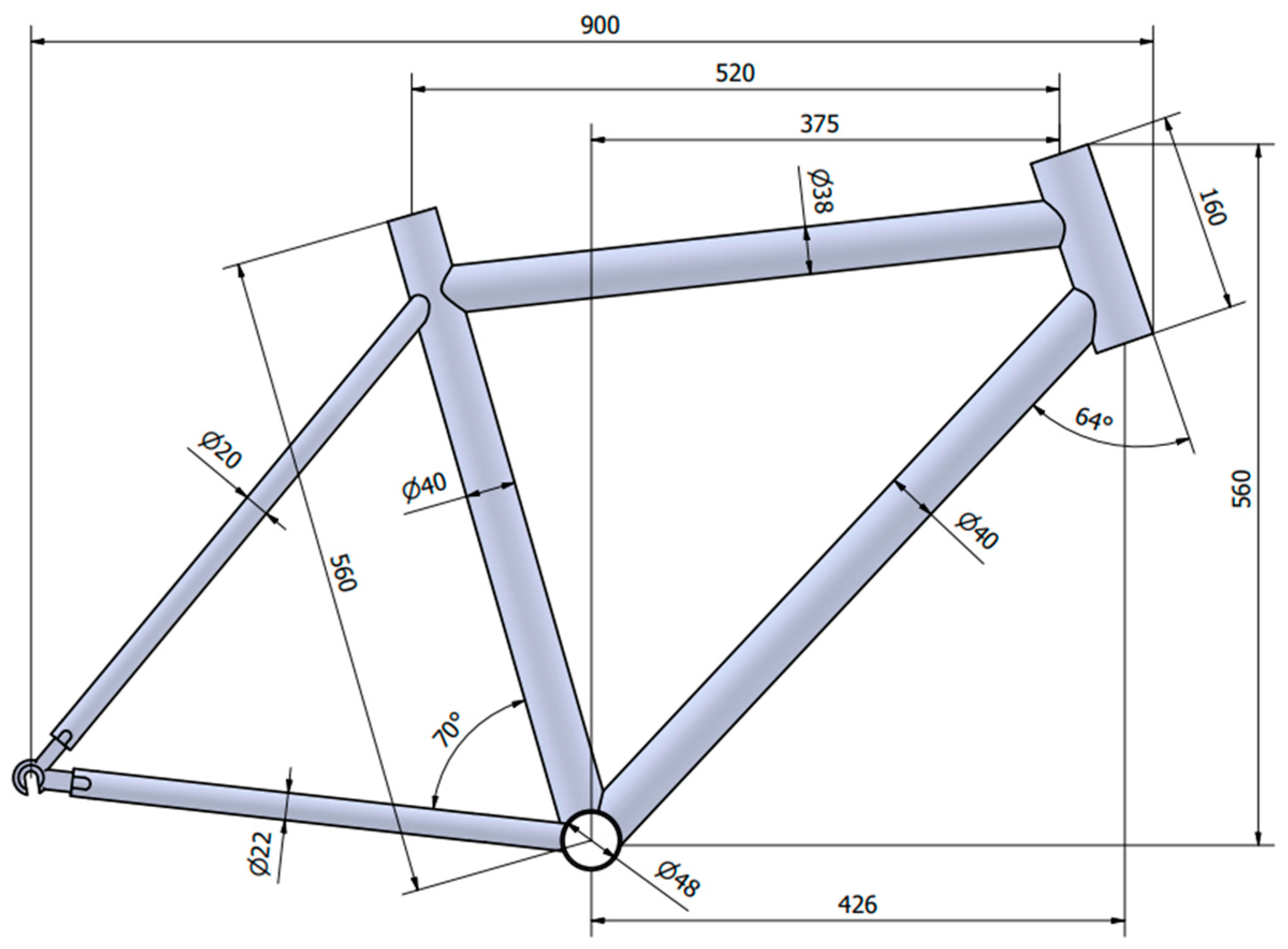
The selected type of bicycle frame is a road frame, which is characterized by a long, steeply sloping top tube and a short head tube. The rear triangle has two tubes, both in the upper and lower parts of the structure, at the end of which are hooks that allow the mounting of the rear wheel. The rear tubes usually have a smaller diameter to dampen vibrations. The most important dimension when choosing the size of a bicycle frame is the length of the seat tube. In the presented case, this value is 560 mm, and the thickness of each tube is 1 mm. The dimensions of the frame are shown in
Figure 2.
The material selected for the construction of the bicycle frame is the aluminum alloy 6061, known for its versatile applications across various industrial domains. This alloy is a popular choice in several key industries, including aviation, where its strength-to-weight ratio is crucial; the automotive industry, which benefits from its durability and lightweight nature; the marine industry, where its resistance to corrosion is essential; and the food industry, where its non-toxic and non-reactive properties are vital. One of the primary advantages of using aluminum alloy 6061 for the bicycle frame is its relatively low mass, which makes the bicycle lighter and easier to handle, enhancing the riding experience. Additionally, this material is known for its high stiffness, providing structural integrity and stability to the frame, which is crucial for safety and performance, especially in rugged or high-speed cycling scenarios.
Furthermore, the detailed composition of this alloy, as per the EN 573-1 standard [
29], is meticulously outlined in
Table 1. This table provides a comprehensive breakdown of the percentage content of each element in the alloy, offering insights into how each component contributes to the overall properties of the material, such as its strength, flexibility, and resistance to various environmental factors [
30].
Aluminum 6061 is a material with good mechanical properties and good resistance to corrosion. It is characterized by good weldability and is easy to work with, including bending, forging, and stamping. This material is also malleable, allowing it to be shaped in any desired way. The final strength is achieved through heat treatment. Aluminum alloy 6061 in the T6 state is most commonly used for the construction of bicycle frames. Selected key material properties have been presented in
Table 2 [
31].
The use of aluminum alloy 6061 aligns with several key principles of sustainability:
- −
Resource efficiency: The use of aluminum alloy 6061 in the bicycle industry promotes resource efficiency, where materials are reused and recycled, reducing waste and the depletion of natural resources.
- −
Durability: The high stiffness and strength of 6061 aluminum alloy contributes to the durability of bicycle frames, which means longer life cycles, reducing the frequency of replacement and reducing the environmental impact associated with manufacturing new products.
- −
Light weight: The light weight of this alloy contributes to energy efficiency in transportation. Lighter bicycles require less energy to operate, especially electric bicycles, leading to reduced energy consumption and lower carbon emissions.
- −
Non-toxicity: This aligns with sustainable practices, ensuring that products are safe for consumers and do not harm the environment.
- −
Versatility in Applications: This versatility means that the environmental and economic benefits of this material can be spread across multiple sectors, minimizing its negative impact.
2.2. Robotic Station
RobotStudio 2022 software was used to simulate robotic welding process and energy consumption analysis. It enables offline programming of the industrial robot, as well as visualization of the station and simulation of work before launching in reality. The RobotStudio software manufacturer states that simulated work in a virtual environment corresponds to reality (for new robots). In newer robots, there is an additional possibility of viewing and recording the actual parameters of the station. In the virtual environment (for external parts, e.g., drives or sensors), the correct operating ranges must be assigned.
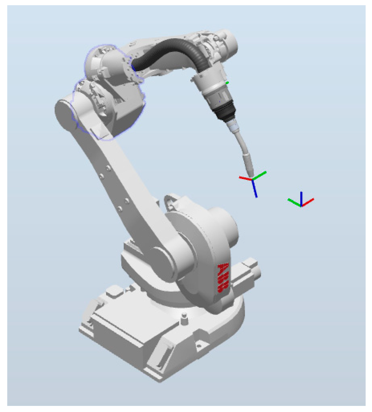
An IRB 1660ID_6_155 industrial robot with a load capacity of 6 kg and a range of 1550 mm was used to build the robotic station, with positioning repeatability of 0.05 mm. The robot has integrated wiring located in the middle of the arm, ensuring failure-free operation between wiring and robot parts. The welding process was carried out using a Binzel_ID_22 ABB welding head attached to the robot (
Figure 3). It is characterized by a burner neck bending angle of 22°. The robot is adapted for MIG arc welding.
Other elements of the equipment of the robotic welding station are presented in
Table 3.
The welding station was fenced with protective barriers. Their main function is to prevent employees from entering the manipulator’s work zone, which is dangerous due to high temperature and spatter resulting from the welding process. The use of a special fence allows you to protect your eyesight by maintaining an appropriate distance from the work area. Moreover, it minimizes the risk of an accident caused by contact of an industrial robot with an employee during the process.
Additional elements of the station’s equipment are welding fume extraction hoods, which are used to remove fumes and gases generated during welding. Their function is to maintain a safe work area by reducing harmful substances polluting the air.
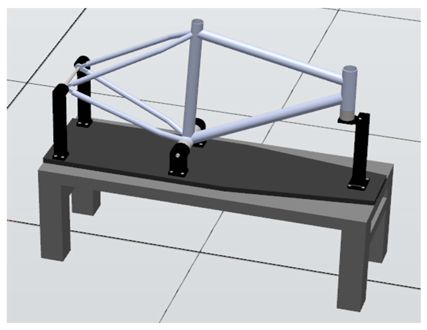
In the first design variant, the bicycle frame was placed in a vertical position on a stationary table (
Figure 4). The handle ensured the stability of the frame during processing and the impossibility of changing its position. In this mounting method, the most important thing was to support the bottom bracket sleeve and the frame head using rollers and hooks, the position of which was fixed with a double-threaded screw. Both the shafts and the screw were screwed to the columns, which are attached to the plate.
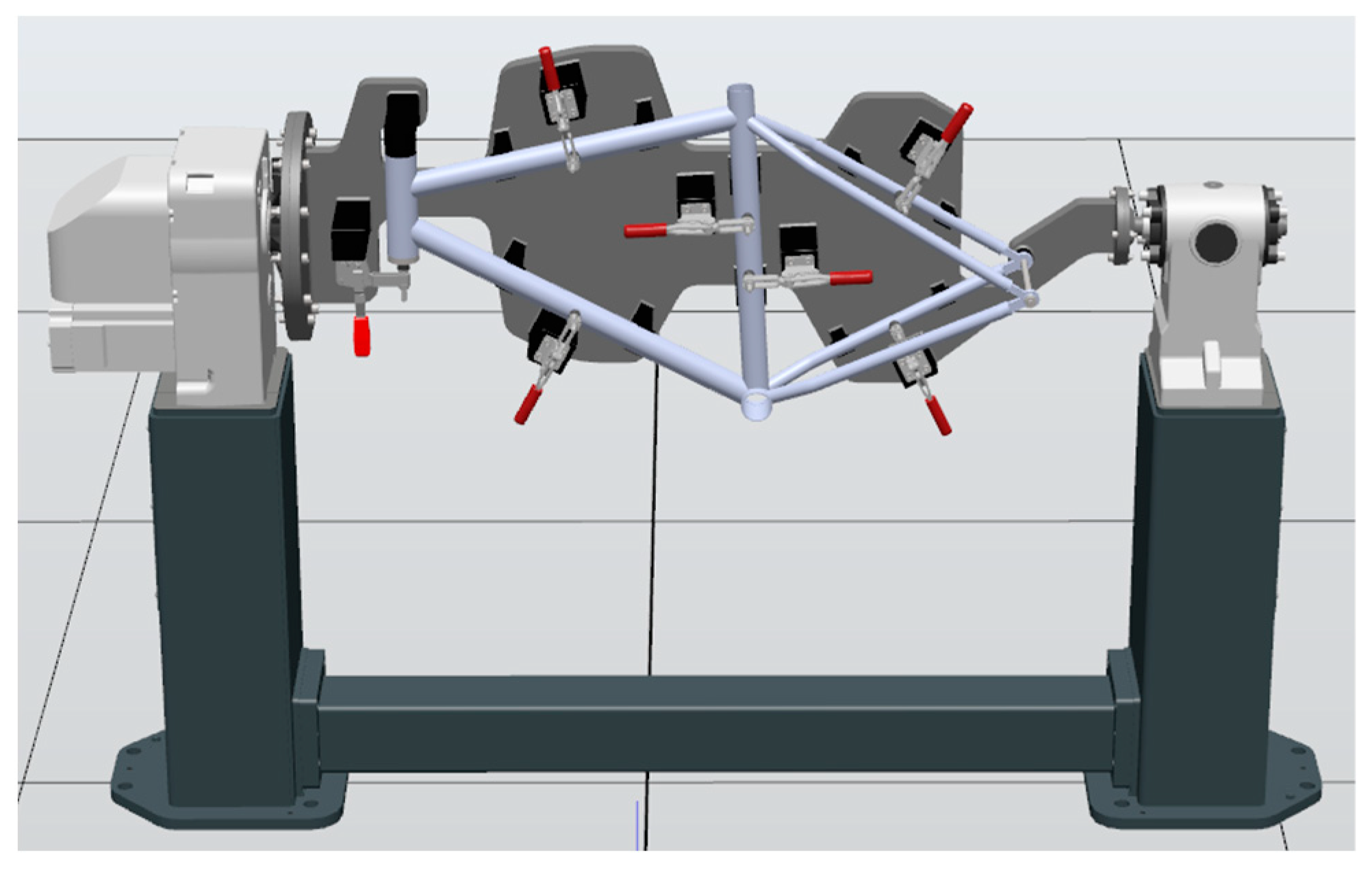
To analyze the second variant, the IRBP_L300_L1250 rotary positioner was used to manipulate the object during the welding process (
Figure 5). It is a single-axis positioner enabling the installation of an element with a handle with a total weight not exceeding 300 kg and a length of up to 1250 mm. To attach the bicycle frame to the positioner, it is necessary to design a special holder that allows the frame to rotate and support it during the welding process. In this mounting, in addition to determining the position of the frame head and hooks, as in the case of the first variant, supports welded to the plate were used to support the pipes. Additionally, vertical and horizontal clamps were used, screwed to the columns. Each variant of the mounting brackets was made using Autodesk Inventor Professional 2023 software.
The welding speed was set to 30 mm/s. In each of the analyzed variants, the industrial robot moved along a programmed motion path in accordance with the specific sequence of welding presented in
Table 4.
The article presents two configurations that most often appear in the configurations of robotic stations. They result from the authors’ experience and literature review. The first step is usually the decision to use a welding robot, adapting it to the existing position and determining the profit/loss from a given solution. Then, to improve the process, further configurations and simulations of the station are performed, usually additional positioners, which can affect production efficiency but also aspects of energy consumption.
2.3. Methods of Assessment and Comparison of the Robotic Process
2.3.1. Tool Path Analysis
The TCP Trace module was used to analyze the movement path of an industrial robot tool in RobotStudio. It enables tracking of the tool center point (TCP). Displaying the tool path is important to detect a collision between the industrial robot, equipment of the station and the workpiece. Analysis of the movement path allows for corrections to be made in the program and further optimization.
2.3.2. Process Time Analysis
When programming an industrial robot, the speed at which it is to move is defined for each movement. After the program is created, it can be synchronized to the RAPID language and then it can simulate its operation using the Simulation Control module. This makes it possible to track the process and check its total execution time.
Time is one of the most important criteria for assessing a robotic process. Its final value is influenced by the appropriate selection of parameters, positioning accuracy, and the robot’s movement trajectory. It is important to set the approach to the workpiece as short as possible when programming the path to reduce cycle time. In this work, the times of the robotic welding process were compared for two design variants of mounting the workpiece in order to determine the most effective and cost-effective solution.
2.3.3. Robot Movement Speed Analysis
The tool movement speed analysis was performed using the Signal Analyzer module, which is significant in optimizing and adjusting movement parameters. This tool records measurements at a rate of 40 per second, which are presented in the form of rescaled charts. This enables a thorough analysis of the results obtained and checking whether the programmed speed and acceleration values are achieved by the robot. In many cases, it happens that an industrial robot is unable to achieve the defined speed, which is not visible during program simulation.
Table 5 lists the tested variants of the robot’s movement speed in each type of object clamping.
2.3.4. Energy Consumption Analysis
An important parameter considered when building a robotic station is the total energy consumption. It can be estimated using the Signal Analyzer module by selecting Total Motor Energy. During the research, the impacts that changes in the speed of the robot’s movement between welds and the choice of the method of mounting the object have on energy consumption were analyzed. The generated charts enabled accurate tracking of energy consumption, which made it possible to observe what caused the increase in this value and which sections of the process should be optimized. The purpose of this analysis was to determine the minimum energy needed to complete the movement path of an industrial robot at a real station. The simulations carried out allow for the selection of the best process variant and optimization of the station in terms of energy consumption, leading to a reduction in production costs.
2.3.5. Cost Analysis
Cost calculation is to choose the most profitable solution, taking into account energy costs. The scope of this analysis is the calculation of monthly profit and unit cost.
3. Results and Discussion
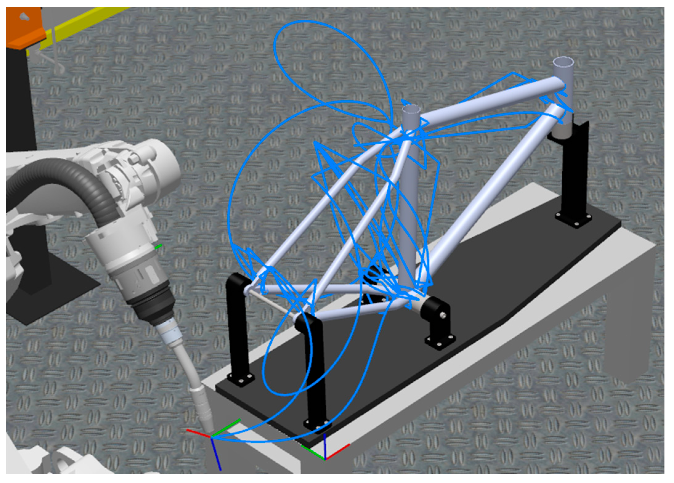
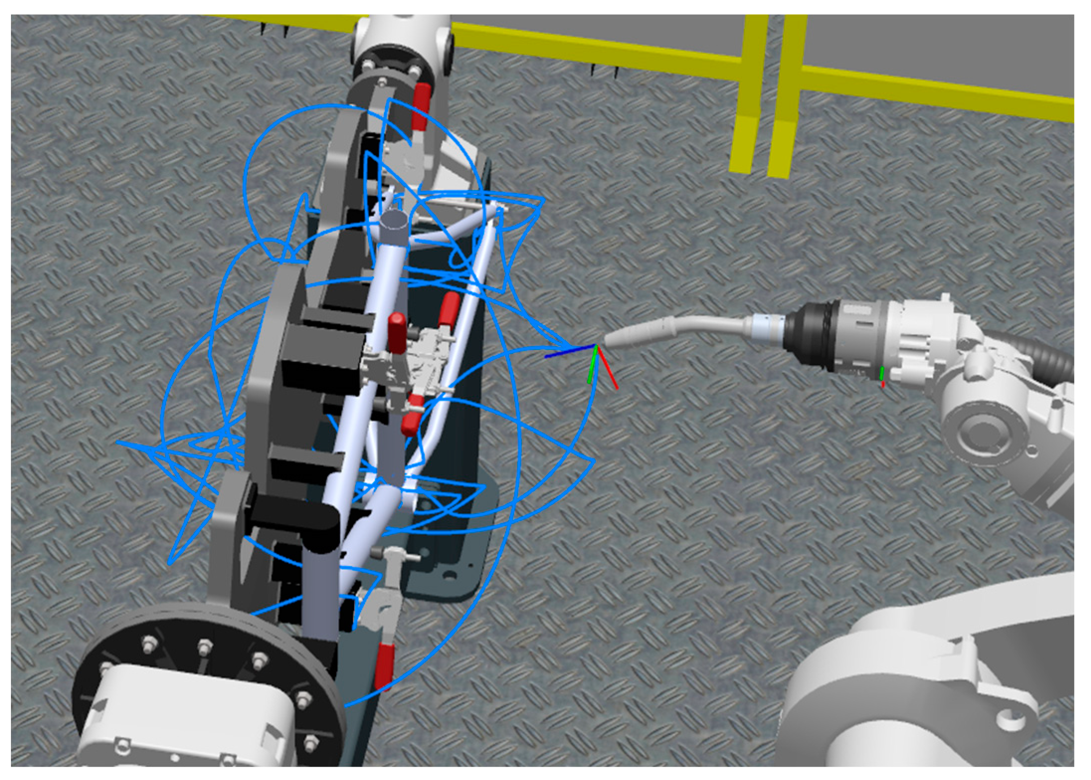
3.1. Tool Path Analysis
Figure 6 and
Figure 7 show the obtained motion trajectory of the robot welding the bicycle frame for two variants of the station, with a stationary table and a rotary positioner. The process uses three types of TCP robot movement trajectories: in a straight line (MoveL) to ensure collision-free access of the head to a given point as a result of moving the head in one axis, in an arc (MoveC) mainly for welding pipe elements, and a curve (MoveJ) for idle movements, the use of which was dictated not by the movement path but by the fastest possible way to reach the programmed position.
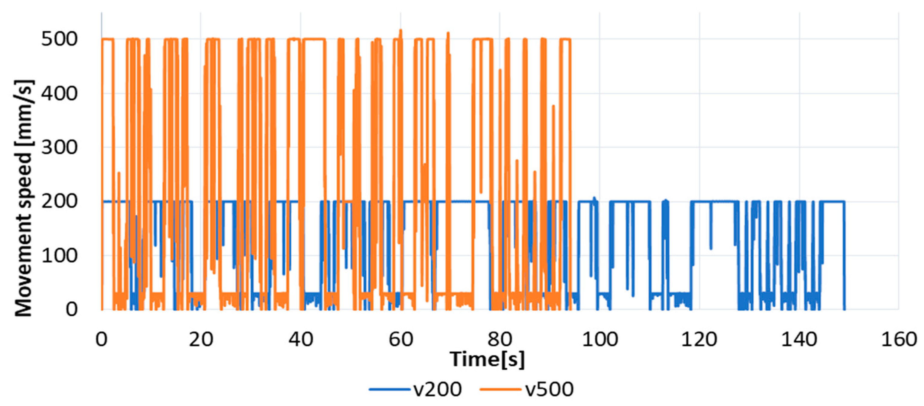
3.2. Process Time and Robot Movement Speed Analyzes
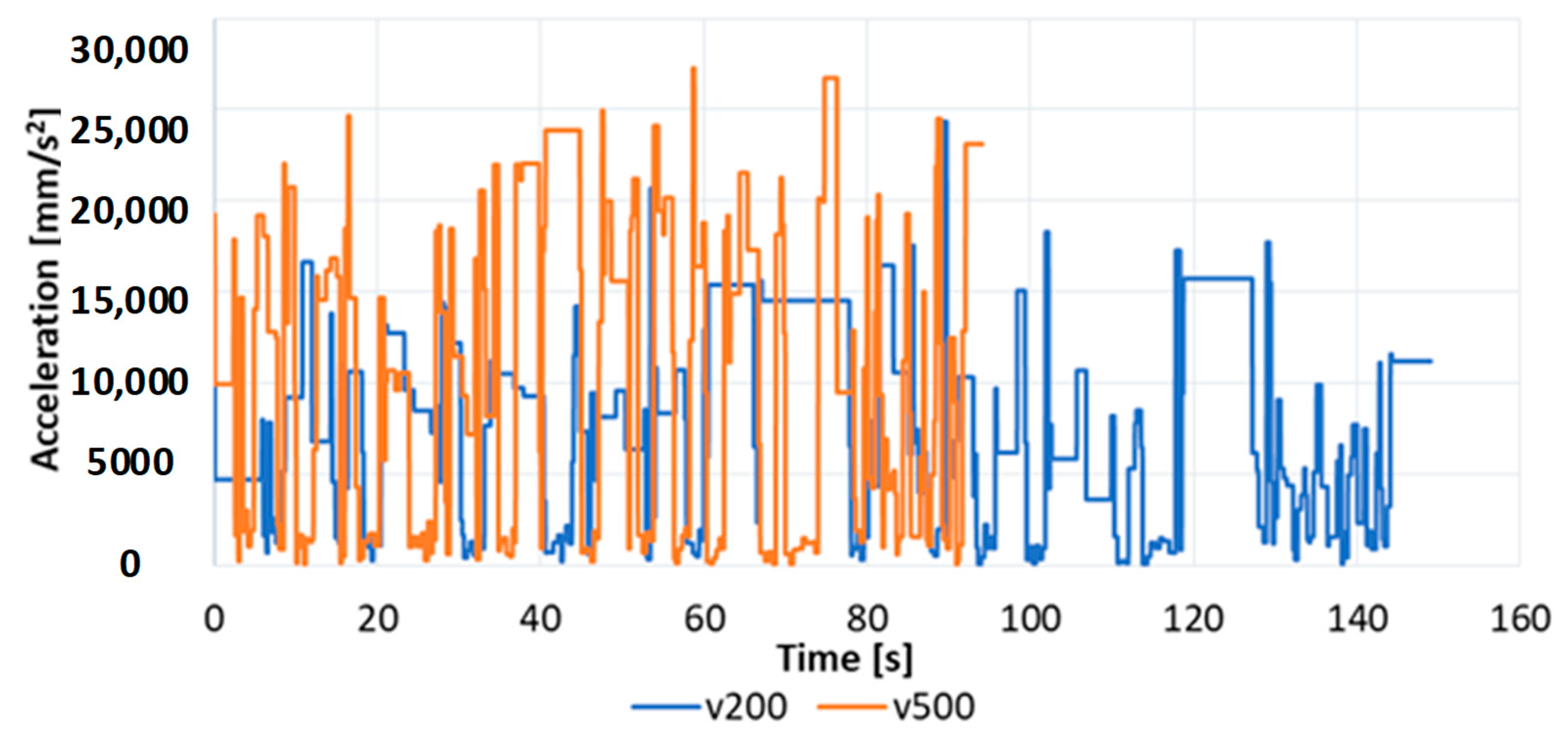
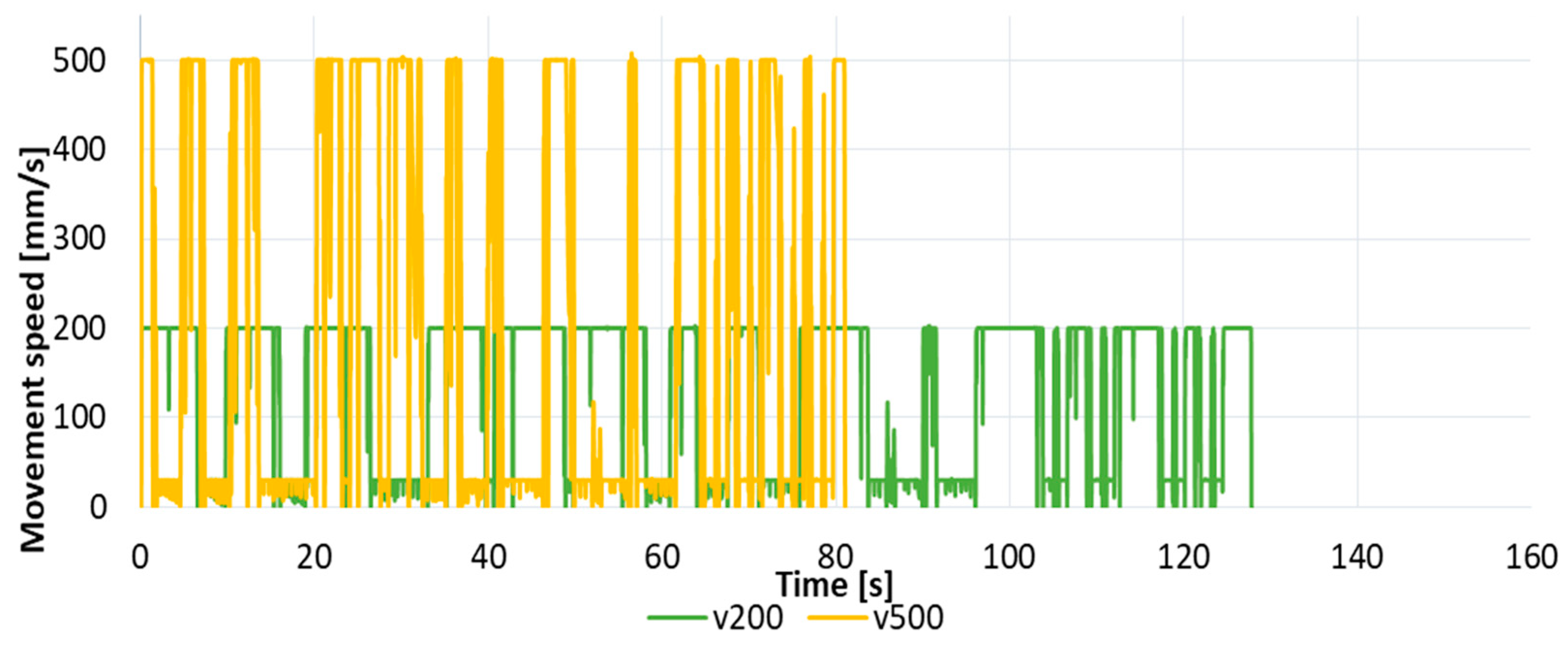
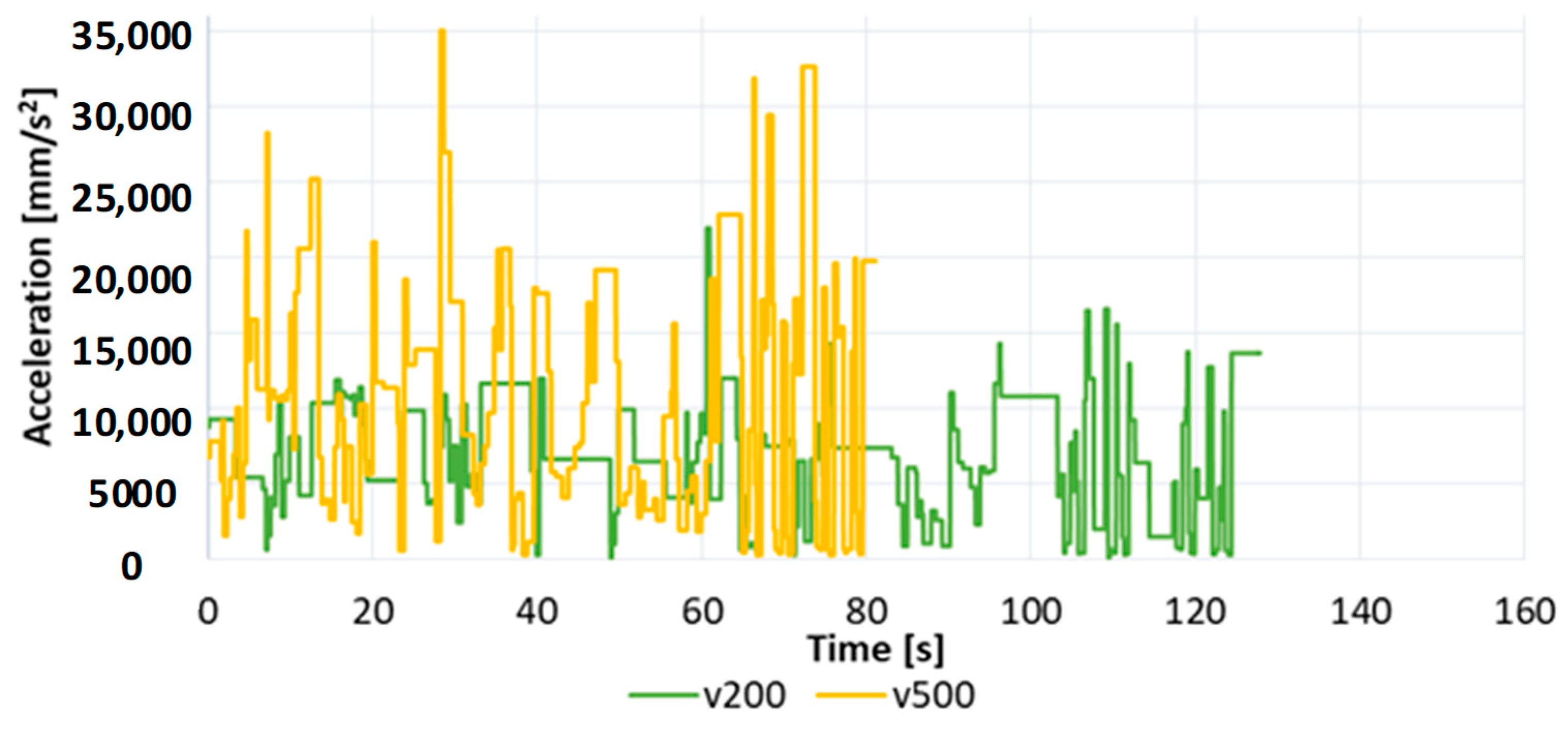
Important parameters considered during the research were the speed and acceleration of the robot’s movement. The welding process took place at a speed of v30 mm/s, and in the remaining parts of the path the speed was changed to v200 mm/s and v500 mm/s. The obtained results of the movement speed as a function of time for the variant with a stationary table are presented in
Figure 8, and movement accelerations in
Figure 9.
The largest peaks in the graphs were created when the robot moved between the welds being made. In the case of v500 speed, when the distance between two programmed points is small, the robot is not able to achieve the maximum set speed. This is due to the kinematic limitations of the robot. The situation is similar in the case of the obtained movement acceleration, where the highest values were recorded when the sections performed were the longest, and during short sections the robot does not achieve high acceleration values. The increase in the speed parameter resulted in a reduction in the duration of the welding process by 55 s.
The results of the analysis of movement speed signals as a function of time for the variant with a rotary positioner are shown in
Figure 10, and movement accelerations in
Figure 11.
The analysis shows that when a rotary positioner is used, there are fewer peaks on the graph. This is caused by a smaller number of welds, because in the first variant many welds are made as split welds. Similarly to the previous mounting variant, the time during which the robot is able to maintain the defined speed depends on the length of the section covered by TCP. It can be observed that for the speed parameter v200, the robot is able to move at the maximum set speed for a longer time. This is due to the limitations of movement and kinematics of the robot. Increasing the speed from v200 to v500 resulted in a reduction in the process duration by 47 s.
Table 6 presents the results of simulation time and consumption for two variants of the station at the declared movement speeds. The choice of mounting the bicycle frame significantly affects the time and costs of the process. In each case of set speeds, when using a rotary positioner, the simulation time was shortened by over 14%, and the total energy needed to complete the process was reduced by over 10%. Changing the robot’s movement speed from v200 to v500 causes significant changes in the process duration. Increasing the robot’s movement speed reduces the simulation time by almost 37%. The change in the speed value is associated with a slight increase in the total energy consumed, which is 3.3% for variant 1 and 7.4% for variant 2.
Performing a simulation in a virtual environment brings many benefits, as it can provide information about process time, energy consumption, signal operation or movement speed. It is possible to define the work space, detect collisions and track the movement trajectory, which is very important at the stage of building and designing the workstation.
Taking into account mathematical relationships, increasing the welding speed should reduce the welding time. However, in practice, it turns out that despite the declaration of movement at a speed of, e.g., 500 mm/s, the robot may not be able to achieve the set speed. This can be due to, among other reasons, the length of the path (too short to achieve the set speed) and the limitations of the drives (i.e., the value of the calculated accelerations to obtain the set speed exceeds the maximum values of the drives). The welding speed depends on the welding current and the welding arc voltage. Increasing the welding speed causes a decrease in the penetration depth (the weld is narrower, undercuts can appear), while decreasing the welding speed is accompanied by an increase in the penetration depth, face width, and riser height. When the welding speed is to be changed, the wire feed speed or arc voltage must be changed to maintain a constant weld shape. Setting and adopting a given welding speed should be confirmed by tests.
3.3. Energy Consumption Analysis
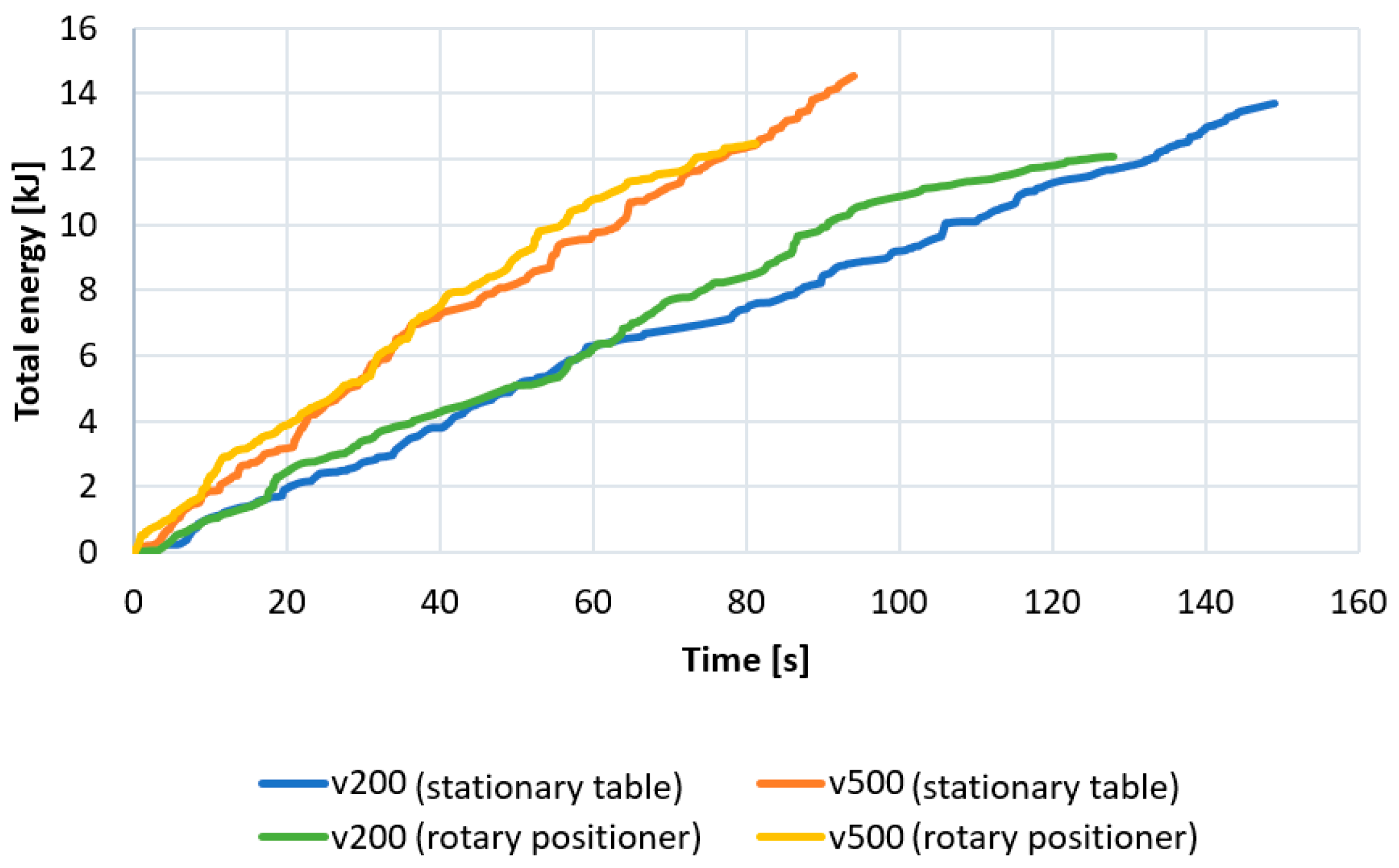
The influence of the mounting variant and the programmed robot movement speed on the total energy needed to carry out the welding process is shown in
Figure 12. The positioner is an element of the construction of the welding station (fully programmable and controllable). At each point of the robot’s trajectory, a monitored position is saved. The positioner is an integral part of the system and the energy it consumes is included in the total energy.
It can be seen that for both the v200 and v500 movement speeds, the energy consumed when using a rotary positioner is lower. This is due to a shorter welding cycle time and easier access of the head to the places where the material is joined, which reduces robot movements related to setting the appropriate configuration. In both mounting variants, the energy consumed is lower when the robot movement speed is set to v200. When the declared speed is v500, the robot consumes more energy due to frequent and large changes in acceleration values when the robot moves between welds.
3.4. Cost Analysis
Cost calculation is also very important, which involves determining the unit cost with a detailed cost structure. Using the division calculation, the unit cost is calculated as the quotient of the sum of production costs and the production volume, written as
where
Cu is the unit cost;
TC is the total cost (purchase cost, energy, labor costs);
P is the production volume.
Table 7 shows an approximate cost calculation for welding a bicycle frame in several variants. Variant II (rotary positioner) is associated with the greatest profits despite the higher costs of purchasing the robotic station. The unit costs for variant I, stationary table, are €0.36 (v200) and €0.23 (v500), and for variant II, rotary positioner, are €0.41 (v200) and €0.26 (v500).
Theoretical cost can differ from real costs. It depends on the input data adopted, including the cost of electricity, the cost of a man-hour, the cost of producing one piece of product, or the cost of purchasing a station and the related purchase currency exchange rate. The economic calculation presented in the article contains the most important values of the station costs and its calculation. It allows for the quick selection of a solution variant and can be used for other examples. In practice, it is necessary to take a broader look at the entire design process and determine in detail the actual costs that have not been included in the overall calculation, e.g., environmental consents, permits, safety systems, or changes during project implementation.
4. Conclusions
The construction of a virtual station and offline programming enable checking the correctness of the created program code and selecting appropriate parameters and working conditions before starting the actual production process. This approach is particularly important from an environmental point of view, enabling the selection of the most energy-efficient production process with the lowest energy costs.
The method of attaching the bicycle frame using a rotary positioner reduced the welding process time by 14% and the total energy consumption by 10%. The ability to rotate the element while the robot moves simultaneously during welding makes it possible to reduce the distances and number of welding head movements, which increases the efficiency of the process.
The welding process using a stationary table makes it impossible to perform some welds in one track due to difficult access of the head to the welding zone. Therefore, it is necessary to make split joints, which reduces the strength properties of the material connection point, the service life of the product, and thus can cause the ecological consequences of scrapping a non-durable product.
The movement speed of the TCP robot affects not only the duration of the process, but also the energy needed to complete it. Increasing the speed reduces welding time and slightly increases energy consumption. This is due to the increase in the range of accelerations achieved by the robot.
The robot’s TCP movement speeds depend on its kinematics and the length of the programmed movement section. If the distance is too short, the robot is not able to reach the maximum set speed.
In order to optimize the process, further research is possible to experimentally determine the most appropriate welding speed and robot movement while maintaining the profitability of the production process. It is also worth analyzing the costs of not only the construction of the facility, but also its operation, taking into account the elements of sustainable development [
32]. Optimizing energy consumption in robotic stations using simulation tools is an important aspect of modern industry [
33].


