Article

Novel ‘Closed’-System Approach for Monitoring the Technical Condition of Railway Tracks

by
Iryna Bondarenko
1,
Vaidas Lukoševičius
2,* and
Larysa Neduzha
3
1
Institute of Mechanical Engineering and Transport, Lviv Polytechnic National University, 79000 Lviv, Ukraine
2
Faculty of Mechanical Engineering and Design, Kaunas University of Technology, Studentų Str. 56, 44249 Kaunas, Lithuania
3
Department of Technical Mechanics, Ukrainian State University of Science and Technologies, 49010 Dnipro, Ukraine
*
Author to whom correspondence should be addressed.
Sustainability 2024, 16(8), 3180; https://doi.org/10.3390/su16083180
Submission received: 17 February 2024 / Revised: 24 March 2024 / Accepted: 9 April 2024 / Published: 10 April 2024
(This article belongs to the Special Issue Sustainable Railway Construction, Operation and Transportation)

Abstract

:
Assessing the technical condition of a railway track throughout its service life is crucial to ensuring functional safety. However, it is important to note that current approaches have theoretical and practical gaps that require attention. The purpose of this study is to discuss the reconceptualization of an integrated approach to assess changes in the technical condition of railway tracks caused by rolling stock over their service life. Improving existing systems for assessing the condition of the track can be achieved by modifying the model concept and, subsequently, the measurement and assessment procedures. This paper presents an alternative method for addressing technical issues related to the monitoring and diagnosis of railway tracks, with a particular focus on natural phenomena: energy transfer by elastic waves. The primary aim of this work is to propose an approach for designing a ‘closed’ measurement system that enables tracking of the cause-and-effect relationship. This system takes into account both the elastic dissipative characteristics of the track–rolling stock interaction and the influence of the dynamics of various components in the ‘train-track’ system.

1. Introduction

Compared to other man-made structures, it can be observed that a railway track operates under unique conditions. This is due to the accumulation of local plastic deformations in all its elements [1,2,3,4,5]. This study aims to present the discourse on the reconceptualization of an integrated approach to the assessment of the change in the technical condition of a railway track under the action of rolling stock throughout its useful life, which is highly important in efforts to ensure the functional safety of the railway track. It is proposed to improve existing systems for the assessment of the condition of the track by making changes in the model concept and, consequently, in the measurement and assessment procedures. In this way, it is possible to study the variation of the parameters of the deformability process over time, which are important factors in the assessment of the track’s ability to operate within an acceptable level of risk.
The railway tracks are studied using local elasticity indicators [6,7,8,9,10] and geometry monitoring indicators [11,12,13,14,15,16] or similar indicators, which are obtained by numerical processing of data provided by the measurement systems of a track recording car vehicle. Diagnostics of the technical condition of a railway track cover the following aspects [17,18,19,20,21,22,23,24,25]:
  • Study, definition, and classification of its condition and symptoms as signs of manifestation of a process;
  • Design of methods for the detection of symptoms;
  • Selection of monitoring and measurement equipment;
  • Forecasting of changes occurring in the track structure under the action of rolling stock, atmospheric, and other conditions, as well as changes depending on the duration of operation;
  • Determination of the periodicity of tests.
The contemporary approach to the assessment of changes in the technical condition of the railway track under the action of rolling stock during the entire service life includes assessment of the following [26,27,28,29,30,31]:
  • Natural indicators of elasticity of the railway track;
  • Geometric indicators of the condition monitoring of the railway track structure or similar indicators obtained by numerical processing of data from the measurement systems of the track measuring car.
The description of the parameters included in the system of investigated parameters usually contains the following [32,33,34,35,36]:
  • Characterization, significance, and scope of application;
  • Analysis of tolerances or other limit values;
  • Test or measurement methods, equipment, and measuring equipment used;
  • Precautions related to the process of change of the parameter under investigation and facilitating the prediction of behavior.
The existing system for the assessment of the technical condition of objects was developed under the conditions of conceptual representation, where the key assessment criterion used in decision-making has been based on the economic rationale that ensures compliance with the technical parameters of object properties such as strength, stability, and durability. The contemporary conceptualization has evolved towards ensuring the safe manufacture, operation, and disposal of technical objects. Therefore, the economic criteria have become less prevalent. Instead, new requirements have emerged.
The fulfillment of the new requirements is aimed at ensuring comfort and health both for people using and living in the sustainable system of technosphere objects and for the environment, as the main component to ensure comfortable and healthy living for people and provide resources for the technosphere [37,38,39,40]. This change in conceptual vision is impossible without changing approaches towards the investigation of natural phenomena and the creation of technosphere objects.
This article proposes an alternative approach to addressing technical issues related to monitoring and diagnosing the technical condition of railway tracks, with particular emphasis on natural phenomena. The primary aim of this work is to propose an approach for designing a ‘closed’ measurement system that enables tracking of the cause-and-effect relationship. This system takes into account both the elastic dissipative characteristics of the track–rolling stock interaction and the influence of the dynamics of various components in the ‘train-track’ system. This work is a continuation of the research direction, the results of which are contained in [39,41,42,43,44].
The following objectives have been pursued throughout the duration of the research:
  • Implementation of ‘awareness’ dimensions;
  • Applicability of the method for high-speed traffic and freight traffic at different axial loads;
  • The possibility of estimating the elastic dissipative characteristics of track and rolling stock structures;
  • Possibility of estimating stiffness parameters both separately for the elements and the whole ‘rolling stock–track’ system.
The main provisions of this article are summarized as follows. First, the main theoretical provisions of elastic wave theory are presented. These provisions are used as a basis for modeling the prediction of behavior in the interaction between track and rolling stock. Second, the third section analyzes the restraining factors of the existing conceptual vision pertaining to the solution of functional safety challenges within the framework of monitoring railway track condition. In the fourth section, an approach to the development of ‘closed’ measurement systems based on the prediction of track and rolling stock behavior is proposed. The last section presents the outcomes attained in the article and the direction of further development of efforts in this area.

2. Theoretical Basis for a ‘Closed’ Measurement System

Coined many years ago and still widely used today, the term ‘railway track’ encompasses and implies a number of issues related to:
  • Formation of its geometry, implementing the respective route (in terms of both plan and profile);
  • Ensuring the geometry of the position of the two rail threads relative to each other;
  • Provision of certain relations between the force loads of the rolling stock and their corresponding bearing areas and the stiffness of the track structure elements;
  • Ensuring the possibility of physical processes in the design of a jointless railway track due to changes in the properties of rail metal under the action of temperatures.
The issues (1) to (4) listed above apparently could be solved using the approaches employed in geometry and material strength studies, taking into account the assumptions and simplifications adopted in them during modeling. In addition, material strength studies use geometry as a tool for solving the problems investigated, since geometry is a precursor to material strength studies as a stage in the development of modeling. Thus, geometry and material strength studies refer to the same conceptual representation of some phenomenon, the development of which led to the development of the theories of elasticity, plasticity, and viscoelasticity.
The modeling of railway track operation is performed by means of its representation in the form of a complex dynamic system. This mathematical abstraction enables the investigation and description of the evolution of systems over time, and the assessment of this evolution enables the assessment of the variability of systems over time. An investigation of complex dynamic systems requires the input of the following prerequisite information:
  • Set of elements comprising the system and the change in their numbers over time;
  • Functions that determine the correspondence between the elements of a set over time;
  • Representation of the set of states between interacting and/or interrelated elements of the set.
Since this information is very extensive, existing algorithms use simplifications to address the issues under investigation. However, the information on the relationship between these parameters is lost.
It should be noted that the accepted (currently used) conceptual representation involves a universal classification of all systems with respect to the changes occurring in them in relation to real time:
  • Statistical changes, the parameters of which are easily calculated analytically, with their change over time predictable without any particular problems, since they are practically constant within the framework of the investigation;
  • Quasi-dynamic changes, the parameters of which are calculated using differential or integral calculus, since the general character of parameter change has clear regularities within a fixed time interval. Therefore, it is easy to specify a function to describe these regularities. The character of parameter change, however, depends on the real-time rate of physical process (the rate of energy change in the system), and the adopted simplifications of the theories employed do not allow for creating analytical dependencies for universal solutions;
  • Dynamic changes, the parameters of which change without visible regularity. In this case, the nature of parameter change depends on the real-time rate of the physical process (the rate of energy change in the system). Therefore, the theoretical basis for solving such problems is based purely on the description of certain fragmentary phenomena, with the application of simplifications adopted for special cases of a certain class of problems.
In addition, current approaches to account for time in solving the set problems are characterized by two features:
  • Modern technical means register parameter change in complex dynamic systems faster than predicting the changes on the basis of the elasticity theory provisions, which are hardwired in all methods and approaches of both theoretical and experimental studies of the functioning of the railway track. Therefore, there is a dilemma between obtaining the ‘true value of a physical parameter’ and the ‘actual value of a physical parameter’;
  • At present, there is a tendency to outpace the development of intellectual technologies that are based on knowledge extraction and management. The initial information used in the decision-making process is actualized and intellectualized in different subject areas, with further transition to automation of the decision-making process. This is implemented through the development of correct mathematical models and methods of modeling information systems to solve optimization problems.
With these features put to use, there is the possibility of modeling railway track operation with the help of artificial intelligence. This could be based on the application, for example, of combinational logic circuits or neural networks to establish a connection between the characteristics of the impact of the rolling stock on the elements in the track structure and the stress–strain processes occurring under various impacts of the rolling stock. However, this is unlikely to lead to a shift to analytical descriptions of parameter changes in the processes investigated, since fitting never answers the question of what caused the parameters to change when fitting to a particular outcome recorded in the experiment. Furthermore, the question of the ability of artificial intelligence to propose and teach new theories to humans remains unanswered.
Controllability through the application of boilerplate prevails in the adopted and utilized conceptual vision. In reality, however, this approach does not account for the uniqueness of each individual situation. Therefore, there are limitations not only in transferring correlations from one track structure to another without experimental validation but also, for example, in transferring correlation results from the modeling of experimentally validated correlations for a track structure resting on rocky soil to modeling the behavior of the same track structure resting on clayey soil.
Therefore, a change in conceptual vision entails a change in the essence of functional safety management of modern railroad tracks, which is not based on processing all results using artificial intelligence or establishing normative controllability of the processes.
Management of functional safety of the railway track should be based on analytical modeling of the behavior of all elements of a complex dynamic system to predict the scenario of processes depending on all initial factors (operational characteristics of the rolling stock, track repair and maintenance systems, physical and mechanical characteristics of the track and the rolling stock, speed of processes in the circumstances under consideration), conditions (state of elements and design of the railway track, climate and atmospheric changes), and the combinations thereof. Such conceptual approaches may benefit from further development to fully capture the complex relationships between system elements and their parameters over time. This will help avoid oversimplification and loss of valuable information. The management of functional safety of the railway track links the criteria and parameters of the device systems, maintenance, and repair of the railway track, while the systems of monitoring and diagnostics of the technical condition of the railway track are tools for recording these links under different scenarios of processes depending on all initial factors.
Consequently, to consider the transition process from the parameters of one system to the parameters of another, a ‘closed’ system needs to be considered. In the broad sense of the term, closed systems play a fundamental role, as they essentially denote the purity of an experiment free of input factors. Here lies the difference between closed systems and non-closed systems. Closed systems are subject to the arbitrary nature of external influences and therefore cannot provide information about the laws of their nature. Thus, consideration of ‘closed’ systems enables analytical solutions, while consideration of ‘non-closed’ systems enables numerical solutions.
A train traveling on the tracks could easily be considered a physically closed system.
General consideration of motion: The considered process of the movement of one body (car) on the second body (track) is dynamic. Therefore, to consider the motion, one system of reference is needed to demonstrate the change at the interaction of two three-dimensional bodies. This certainly does not exclude the existence of multiple local reference systems. However, the overall process is synchronized in space and time.
For the purpose of simplification, it is assumed that car (B) moves by virtue of the pull of a constant driving force F B = f B ( t B j ) applied to the automatic coupling parallel to the track axis with a certain area of application, and f B ( t ) is a constant value per unit of time, where t B is the time of action of the force, and t B j represents the time of action of the force at a certain moment j .
The main characteristic of the interaction forces between two bodies (car and track) is that the contacts between the wheels of the rolling stock and the rails are constantly moving along the rails. These contacts are sources of impulses transmitted by two bodies (wheel and rail) during interaction per contact time (further referred to as the impact impulse). In light of the wheel–rail contact conditions, the forces transmitted during the interaction time will no longer be constant over time. Therefore, each impact impulse necessarily has the following characteristics:
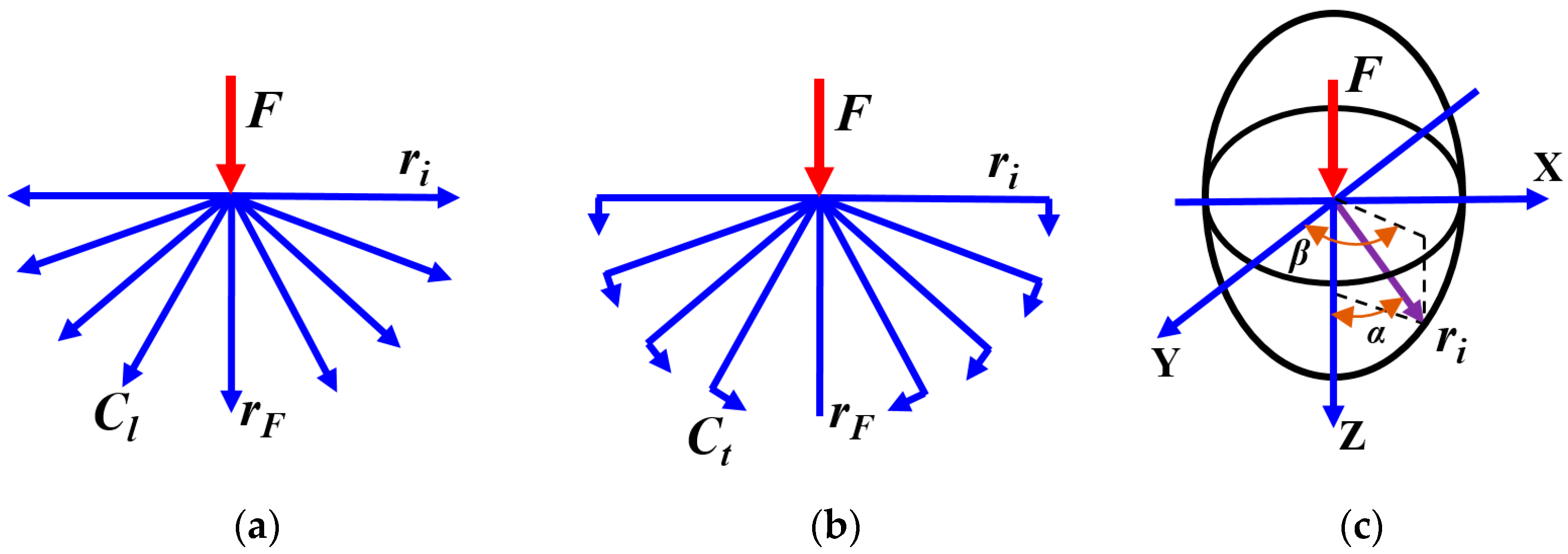
  • The law of change of the impact value over time F K = f K ( t K j ) , where f K ( t K j ) is a variable value per unit of time t K j ;
  • Direction of impact;
  • Time t K of impact;
  • Impact location with defined geometric boundaries and contact area.
In this case, according to Newton’s second law, during the time of interaction, each contact body (wheel and rail) receives mechanical momentum (momentum as a measure of the quantity of motion) P i = p i t i j = f i t i j t i , where p i t i j characterizes the change in mechanical momentum per unit of time j . Thus, during the modeling, all contact areas between all contacting elements will receive an impact impulse subject to the law of change of the impact value over time F i = f i ( t i j ) , characterizing the law of change of impulse over time P i = p i t i j , the character of which will remain unchanged at its transmission along all directions of energy propagation, which corresponds to the directions of wave propagation. This ability of the impact impulse is confirmed by the human ability to recognize musical pieces acoustically (through the sound carried by elastic waves) and to recognize pieces of art (through the image carried by electromagnetic waves).
Typically, in the current concept, when modeling the deformation process of a railway track, time is used as an attribute to reproduce the shape/position, i.e., it is considered from the logical point of view of the onset of a certain deformation. The duration of the processes is taken into account and compared by adopting/changing the frequency values. Thus, the proposed introduction of the law of changes in impulse characteristics over time makes it possible to create a dynamic relationship between the values of force–amplitude–energy. This approach is logical, as it takes into account the onset of deformation and the duration of the process. This approach can help researchers better understand the interplay between these variables and their impact on the overall system.
Generalized consideration of elastic wave propagation in a medium: There are two physical interpretations of the term ‘wave’. The first one reflects the geometric interpretation of motion, while the second one views the ‘wave’ as the means (a transfer/vehicle) by which the energy is transferred. The description of the motion of a continuous medium, using the first understanding of the term ‘wave’, is performed using a vector partial differential equation, which describes the transfer of momentum in any continuum. This description has many limitations because it involves the use of operators that allow calculations to be performed in vector spaces.
To address these limitations, we developed an approach that describes the vibration of railway structures under the influence of rolling stock using the theory of elastic waves [39,41,42,43,44]. For this purpose, the physics of elastic wave propagation is described using geometric vectors that simulate the propagation of elastic waves in space and time (Figure 1).
The oscillations in different directions are described using an impulse, which is a function of the change of force over time. The change in function values is attributed to the properties of elastic waves as they propagate. Thus, the term ‘wave’ has been moved from the first understanding to the second. Further, in the present paper, the second interpretation of the term ‘wave’ is considered.
According to the theory of relativity, all natural phenomena proceed in the same way in any system of measurement. When materials are subjected to various impacts, waves are generated in the former, that is, a sufficient amount of interaction energy ensures that different types of waves occur.
Waves transfer energy without the transfer of matter (the latter may occur only as a side effect). Depending on the characteristics of the material, longitudinal waves (determined by the elasticity modulus) (Figure 1a) and transverse waves (determined by the shear modulus, and in its/their absence, transverse waves are absent) propagate in it (Figure 1b). The determination of whether a wave is ‘transverse’ or ‘longitudinal’ depends on the parameters observed. The concept of a transverse wave, like a longitudinal wave, is conventional to some extent and is related to the way it is described. The rate of energy transfer in a material is the rate of wave propagation in that material. The rate of energy transfer by longitudinal waves is known to be higher than the rate of energy transfer by transverse waves due to the essence of the physical process. Each type of wave carries a certain type of energy. Longitudinal waves carry kinetic energy, which causes the space between particles to be compressed or stretched along the wave propagation. Transverse waves carry potential energy, which causes the particles to move perpendicular to the direction of propagation to the vacated space after the longitudinal wave has passed. Thus, there is a fundamental difference between the direction of wave propagation and the direction of movement of material particles under the action of waves.
According to the conditions of wave appearance, elastic waves at a newly formed contact (wheel–rail) are spherical, and at existing contacts (contact has already taken place, i.e., is being transmitted through already contacting surfaces, e.g., sleeper–ballast–railway bed) are quasi-spherical. The main characteristics of this kind of wave are:
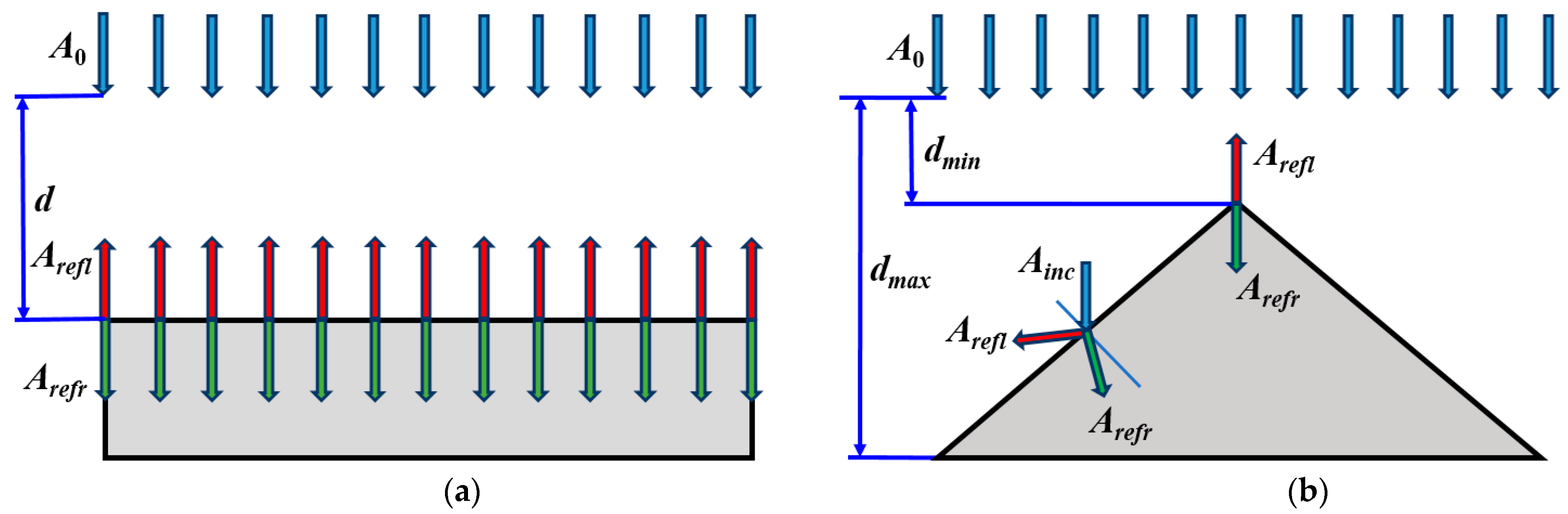
  • The vector of velocity of a divergent spherical wave is directed radially away from the source (the wave diverges radially from the source), while that of a convergent wave is directed towards the source;
  • The amplitude of the spherical wave decreases from the source with increasing distance to the observation point, i.e., it is inversely proportional to the distance to the source.
Thus, with two kinds of waves present in an ideal elastic body, if a force is applied to a point from top to bottom, the wavefront is an ellipsoid (Figure 1c). However, since the direction of propagation of elastic waves is radial, the upper part of the ellipsoid is convergent, and the lower part is divergent. In addition, the maximum values of kinetic energy, and hence the maximum displacements under their action, are directed along the direction of the force. In contrast, potential energy is perpendicular to the direction of the force, irrespective the angle at which the force is applied to the body. Pure longitudinal and transverse waves propagate along these directions, forcing the material particles to move in a straight line. In the other directions, a mixed motion takes place, since two types of waves are in action. Hence, the motion of particles is elliptical, with a change in the direction of the major and minor axes, depending on the value of the angle between the considered radial direction and the direction of the force. If the radial directions are 45° to the direction of the force, the particles on these rays move in a circle in the case of motion in a plane. In any case, these are spatial movements in time, which are described by two components acting at specific time intervals. The Lissajous curve is a reflection of the mixing of waves in different directions. It takes the shape of ellipses that degenerate into straight lines when the phase difference is 0 or π and a circle when the phase difference is π/2, and the amplitudes are equal. This phenomenon is commonly observed in mechanics, where particles oscillate in the direction of wave propagation. To calculate for areas experiencing pure longitudinal waves, use compression or tension calculations. For pure transverse waves, use pure shear. For waves a t = π 2 , use pure oblique bending.
Generalized methodology for modeling with elastic waves: The modeling is based on the following assumptions:
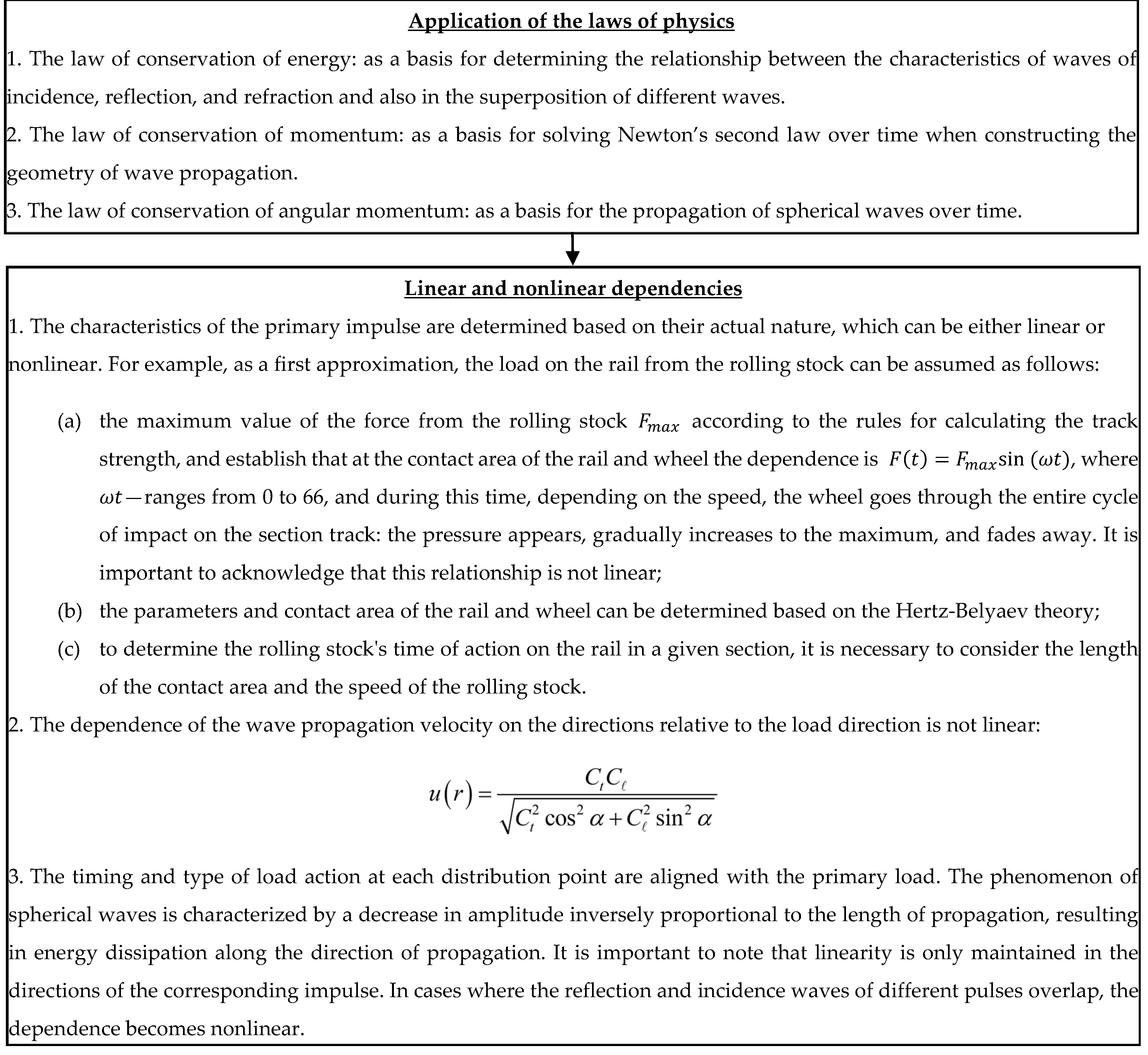
  • Describing the geometry of spherical wave propagation in time in all directions;
  • Taking into account the speed of wave propagation in all directions;
  • Taking into account the geometry of the objects in which the wave propagation took place as a factor in the emergence of new impulses from the chains of incidence–reflection–refraction waves;
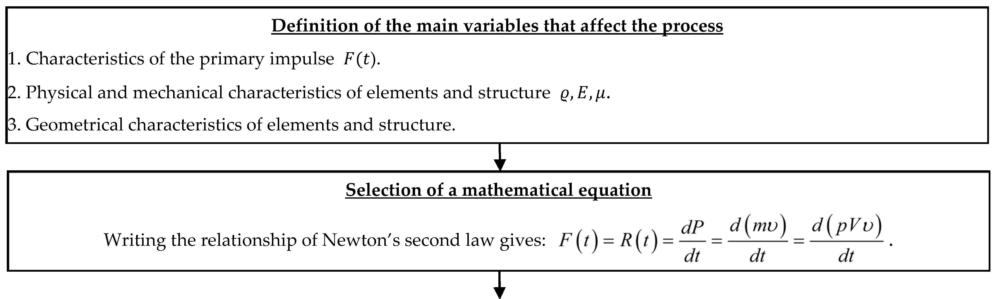
  • Description of the primary impulse as a function of the change in load in time during the action period;
  • Consideration of the property of spherical waves to transfer impulses (change amplitudes) during propagation;
  • Description of the superposition of waves in time and space as a factor of dissipation in the formation of the deformability process.
Figure 2 demonstrates the transformation of the conceptual model into a quantitative and mathematically expressed format. The notations used in the figure are as follows:
F ( t ) —impulse external force acting on the object;
R ( t ) —impulse of the force field acting inside the object;
m —mass of the object, absorbing the influence of an external impulse by means of a force field pulse, which is formed on the basis of a superposition of force waves;
P —momentum;
ρ —density of the material through which the wave propagates;
V —object’s volume, absorbing the influence of an external impulse by means of a force-field pulse, which is formed on the basis of a superposition of force waves;
υ —velocity of particles exposed to the force field that is dependent on the transverse Ct and longitudinal Cl wave propagation speeds in a particular medium;
E —Young’s modulus or the modulus of elasticity;
μ —Poisson’s ratio;
α —angle of wave propagation is defined as the angle in the vertical plane between the radius of wave propagation at a specific point of the medium and the direction of propagation of the force impulse (ref. to Figure 1c);
β —angle between the radius of wave propagation at a specific point in the medium and the positive horizontal transverse direction of force propagation (ref. to Figure 1c).
The analysis of the conceptual apparatus describing the course of physical phenomena yields the following statements:
  • Elastic waves propagate energy naturally;
  • The energy is proportional to the square of the amplitude of the waves, indicating that the presence or absence of sufficient energy directly impacts the observed changes in natural phenomena. The nature of wave propagation determines the processes of deformability, which refer to changes in geometric, physical, and mechanical parameters in response to physical factors such as thermal, aqueous, acoustic, electrical, gravitational, and radiation (nuclear, X-ray, etc.);
  • Adhering to the regulated parameters of waves during their superposition is crucial for ensuring the proper functioning of elements and structures. These parameters, including elasticity, stiffness, dissipation, and inertia, are indicative of natural phenomena or processes of change observed during testing. By following these requirements in accordance with operating conditions, we can ensure optimal performance and reliability;
  • The study of elastic wave propagation in time and space establishes the cause-and-effect relationship of dynamic stiffness values. This considers the elastic–dissipative characteristics of track structure materials, the geometry of each track structure element, and the relationship between the time of load action (which depends on the speed of movement) and the time of load absorption by each element;
  • The analysis of elastic wave propagation in time and space determines the dynamic stiffness of objects under various dynamic loads and identifies the causes of these effects.
Figure 3 shows three-dimensional diagrams of the propagation of elastic waves with longitudinal and transverse waves. A loading diagram of a rectangular object is also shown, with a load applied to its upper face at point O. Pure longitudinal waves propagate in the direction of the load, whereas pure transverse waves propagate perpendicular to it. In all other directions, both types of waves propagate, as shown in Figure 1c and Figure 2.
A detailed description of Figure 3 follows below.
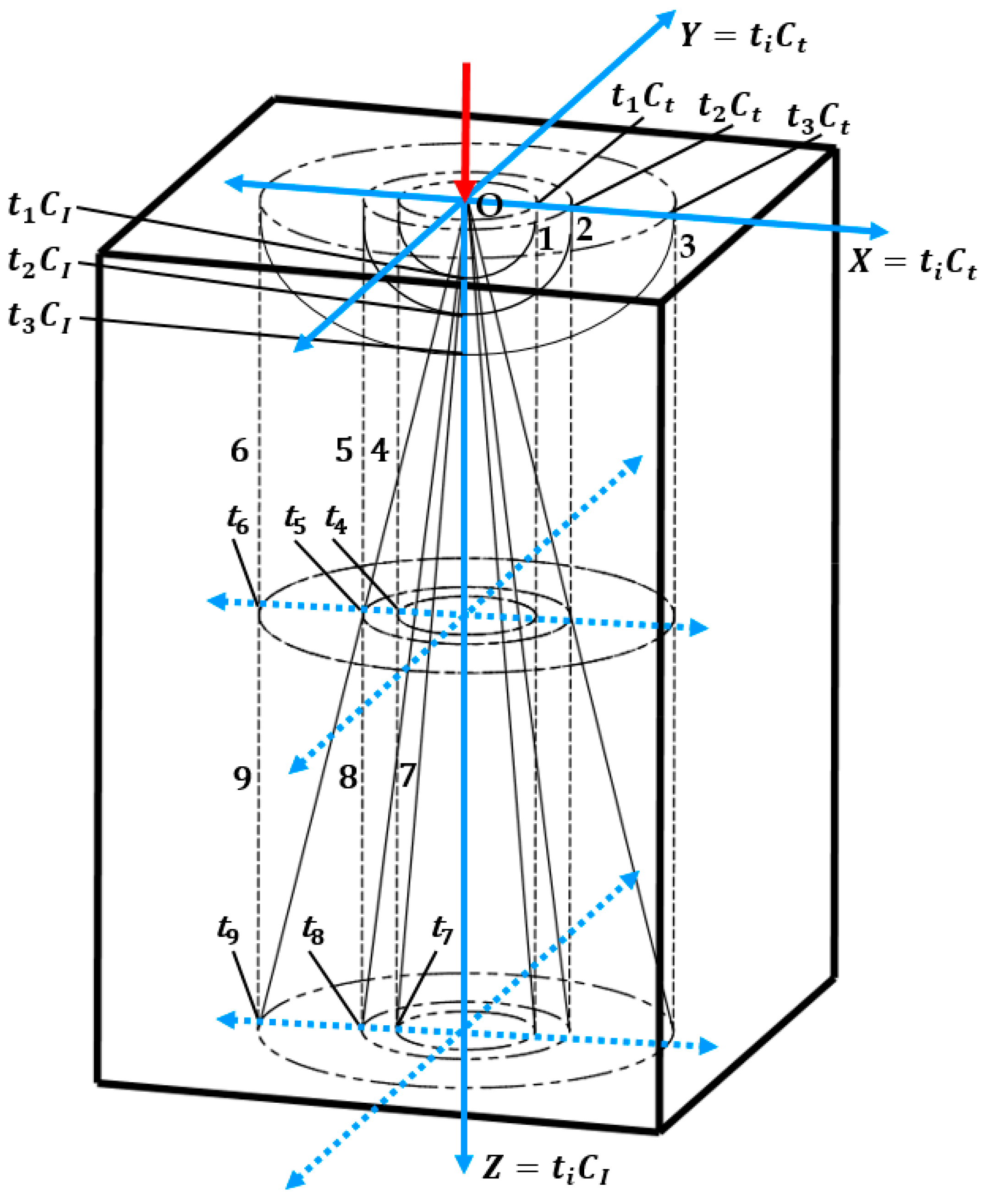
  • The ellipsoids’ surfaces 1, 2, and 3 clearly illustrate the spatial front of wave propagation and the equipotential surfaces of amplitudes, forces, momentums, and energy at times t 1 , t 2 , and t 3 .
  • Cylinders 4, 5, and 6 with radii t 1 C t , t 2 C t , and t 3 C t exhibit equipotential surfaces of moments of forces concerning the direction of force action from times t1 to t9 with confidence.
  • Circles with radii t 1 C t , t 2 C t , and t 3 C t   unequivocally represent isolines (contour lines) of moments of forces relative to point O. These circles are located on the surface perpendicular to the direction of load action at times t 1 , t 2 , and t 3 .
  • The cone surfaces 7, 8, and 9 with the vertex at point O and the axis in the direction of force represent equipotential surfaces of angular momentum at times t 7 , t 8 , and t 9 .
The above properties of waves during propagation are used to define electric fields, equipotential surfaces, the Umov–Poynting theorem, and Ampere’s right-hand grip rule.
The mentioned features of elastic wave propagation lead to the fact that the volume where the propagation of waves occurs over time, with the center of mass being in the direction of the force, can be considered for any impacts. This enables researchers to use the theorem of motion of the center of mass of the system. According to the theorem, the center of mass moves as a material point, having a mass equal to the mass of the whole system and being under the action of all external forces applied to the points of the system. It is therefore not difficult to find the amplitude for the center of mass and proceed to the determination of the amplitude at any point of the medium where the waves propagate, taking into account the time for the waves to reach these points d m i n d m a x .
The law of conservation of energy in wave propagation helps create a chain of incidents: A i n c ; reflection: A r e f l ; refraction: A r e f r , as an obligatory element of the method of elastic wave propagation when reaching any barrier location, whether it be the geometry of the object or the presence of a defect, while accounting for the presence of critical angles of propagation in the material (Figure 4). Consequently, constructing wave propagation regions over time allows for the modeling of the stress–strain process occurring from impacts at any point of the system under consideration, in view of the time when these points are reached by waves, without the use of differential and integral calculus but with the help of vectors.
Usually, the elements of a dynamical system are in constant contact, and most often dealing with the superposition of quasi-spherical waves over time—wave fields—presents the main difficulty in calculating the stress–strain state/process parameters of elements using wave theory. However, this approach has tremendous advantages for understanding the physics of a dynamic process (natural phenomena occurring during dynamic processes) over time, along all directions, and, if necessary, integrally:
Impact impulses F i of the incident waves carry energy and characterize the momentum (as a measure of the quantity of motion P i ) for the potential interaction of both elements and the dynamic system;
Impact impulses of reflection waves F i carry energy and characterize the momentum P i for the dissipation processes occurring during the interaction;
Impact impulses F i of refraction waves carry energy and characterize the amount of motion P i , which determines the inertia of the behavior of the considered elements and the dynamic system itself after the interaction.
Thus, the description of dynamic processes with the help of wave theory allows for modeling time-varying wave fields of various parameters (forces, stress–strain, energies, amount of motion, amount of heat) having analytical dependencies dynamic in time and space. This requires the use of artificial intelligence to predict the scenario of processes depending on all initial factors, conditions, and their combinations.

3. Evaluation of The System of Traditional Approaches, Methods, and Techniques for Determining, Measuring, and Evaluating Parameters of Railway Track Condition Monitoring in Terms of ‘Awareness’

3.1. Analysis of Current Modeling Concept Problems

A review of articles [45,46,47,48] provides a very efficient analysis performed in the considered area, which showed that:
  • ‘Recent decades have shown a certain evolution of approaches to monitoring the condition of various rail transport systems, especially in the context of rail vehicles and track subsystems. The approaches applied to the monitoring of the condition of the rail infrastructure have evolved from manual maintenance, through methods connected to the application of sensors, to the currently discussed today focused on the terms of Industry 4.0′;
  • ‘The application of new concepts triggers a number of potential research agendas that may be developed in the coming years, in addition to those that are still in progress. One of these relatively novel research agendas connected to changes in condition monitoring results from the development of the concept of Industry 4.0. This research agenda can be expressed as a requirement for the automation of diagnostic procedures and methods of generating large amounts of data, which drives the need for more sophisticated methods of autonomous interpretation of vibration-reliant condition-monitoring data. In turn, a large amount of monitoring leads to the collaborative term of Industry 4.0 as big data. This is worth considering in accordance with the discussion of particular aspects of big data applied in condition monitoring in the past decade, such as volume, velocity, variety, veracity, and value. Furthermore, discontinuation of onboard data computing is still a challenge and seems to be a research agenda for the next several years, especially given that the quantity of data continuously increases as an exponential or power function in relation to, for example, the number of sensors used and their measurement directions. This may be supported by the application of various methods of artificial intelligence’;
  • ‘In general, a separate research agenda is to consider the appropriate number of sensors used for a specific need and to determine where to locate these sensors’.
According to the authors of this article, the concepts of real-time computing (RTC) and real-time mode can be used as the main factor of progress, promoting the development of technical and technological processes. However, there has been no progress in pairing these concepts. Hence, the following basic approach towards learning about the dynamic processes remains:
  • Data observation and registration;
  • Selection of function or approximation (which is also selection), taking into account certain conditions under consideration, i.e., establishing correlations between parameters under consideration;
  • Clarification of actual process by taking into account the probability of occurrence of factors.
In terms of the general consideration of motion, the consideration of and relation between the impulses of different contacting surfaces under the existing concept of track condition monitoring during the passage of a rolling stock on the track by means of numerical modeling should be analyzed.
It should be noted that the current development of computer calculus enables the extension of the scope of modeling, initially based on the theory of elasticity. It has therefore become easier to transition from rod calculations to solid modeling of objects with a length much greater than the mass involved in the process.
The development of numerical modeling has essentially contributed to the development of the concept of ‘influence line’, and it has been used to represent spatial changes in the physical field rather than changes in the position of the line from initial to loaded states and back. Moreover, the question of considering the influence of geometric shapes on their stress–strain state within existing objects has been fully resolved within the existing concept. Interpretation of the change in the values of input/initial/baseline data over time continues, presenting the main challenge when describing a dynamic process.
Historically, until some time ago, modeling of track and rolling stock operations used to be performed separately.
Impacts that simulate vibrations on the track side were used when modeling the stress–strain state of a rolling stock as an impact impulse (input data). Their value did not correlate at all with the actual structures or the physical and mechanical characteristics of the track elements. For this purpose, records made during the passage of rolling stock along straight and curved sections of the track, which have different technical conditions, were known as the so-called ‘patterns’.
When modeling the stress–strain state of the elements and the track structure, the input value is the impact of the rolling stock. For this purpose, a method was developed to calculate the change in the force value depending on the type of rolling stock, its velocity, and the condition of the wheels.
In modeling for both objects, it is common to describe the hardness parameters of the elements using stiffness, damping, and input masses actively or passively in the process. Different approaches that combine track and rolling stock models have recently been explored within the existing conceptual vision. As a result, the conceptual vision is reduced to a rigid overlap in time of available results calculated for separate sub-models of track and rolling stock.
For example, paper [49] shows one of the recent modeling approaches using machine learning to monitor the technical condition of the track. The authors of this paper stress absolute solidarity with the authors of the above article in terms of the approach considered within the existing conceptual vision. The work provides great detail and enables us to demonstrate the classic interpretation of the existing conceptual vision. Therefore, Figure 5, Figure 6, Figure 7 and Figure 8 show the tracks and rolling stock models adopted for numerical modeling, as well as their integration into a single model and the dependence of the change in track hardness due to the change in ballast layer stiffness, adopted according to the ‘rail profile of class 4 irregularities’, which is generated randomly, according to the US Federal Rail Administration guide.
Figure 5 suggests that the quasi-dynamic model of track and rolling stock interaction is considered. In this model, the position of the rolling stock along the length of the track characterizes the global matrix, that is, the values of the involved masses, stiffness, and damping, taking into account the data obtained for the track and rolling stock sub-models [49,50].
Neither the initial data nor the equations for solving the global matrix provided in the paper consider time as a parameter of events in the process during matrix formation. The approach towards ensuring discrete balance between different elements of the system facilitates calculation by introducing boundary conditions. This leads to a situation where it is impossible to identify the values of element parameters that would otherwise potentially lead to unbalanced states of the systems, unless the accepted boundary values are violated.
The approach of calculation implies that reaching the boundary value is a risk, without taking into account the influence of time on the emergence of critical situations, since it is assumed that a critical situation inevitably will emerge as a result of critical impact. For example, a maximum force will inevitably produce maximum deflection, regardless of the time the force is applied.
In case existing methods of calculation are applied to investigate the movement of the wheel on the rail and evaluate the changes that will take place when increasing the speed of the rolling stock, the following dependencies would be found:
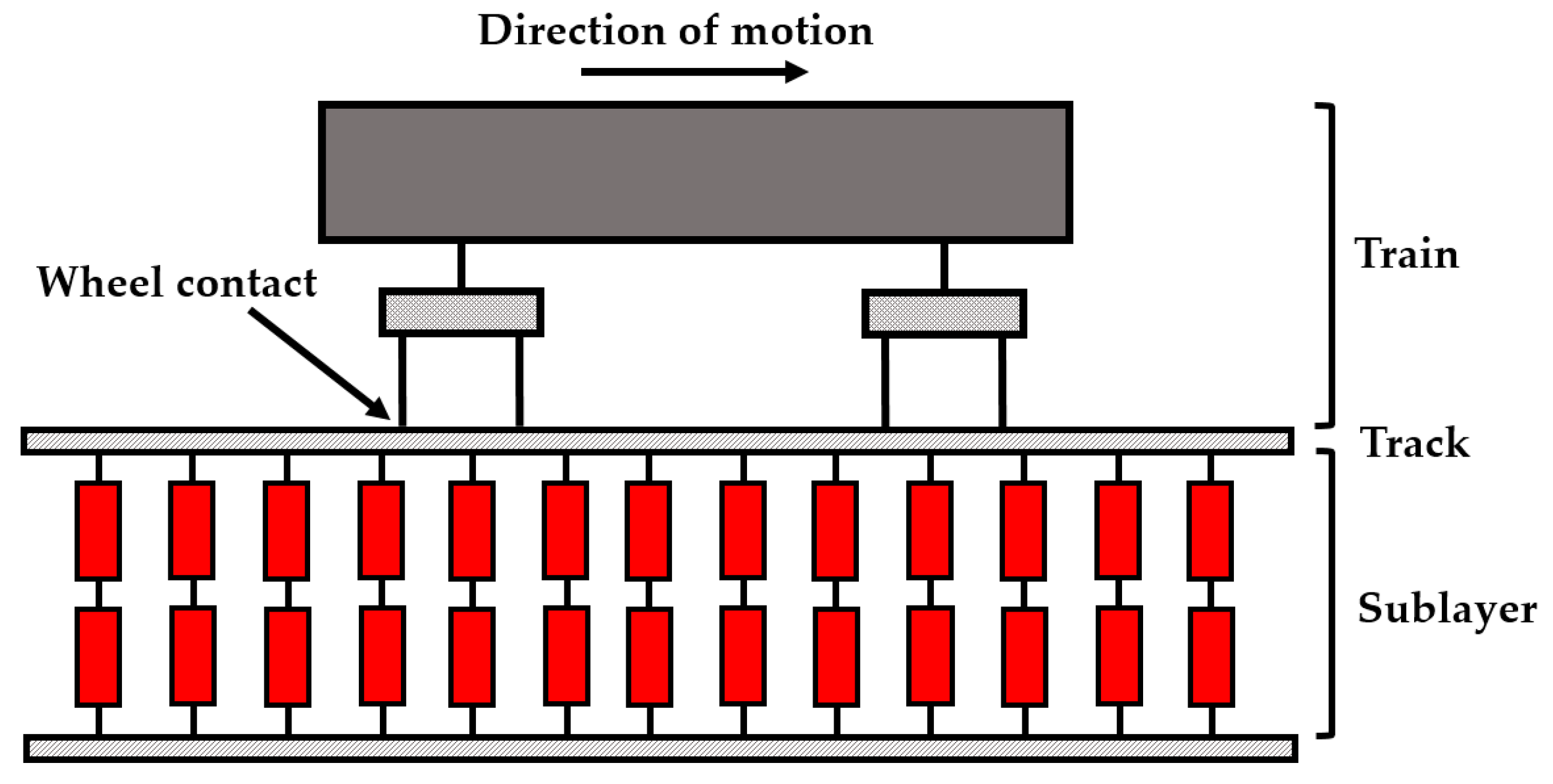
  • Directly proportional slow increase in (i) values of the force from the rolling stock, (ii) wheel/rail contact area, (iii) contact span with increasing train velocity;
  • Rapid curvilinear decrease in (i) the value of wheel–rail contact time and (ii) momentum with the increasing speed.
The second dependence is not used in the existing methodology for calculating the path for strength and stability, but it is illustrative in the analysis of the physical process, demonstrating the reduction in the amount of motion (momentum) in relation to the inertia of the system.
The specified dependences are confirmed in practice, first, by the reduction in rail deflection at increasing rolling stock velocity along the track, regardless of the increase in force dynamic additive, despite the use of a directly proportional dependence between rail deflection and the value of the impact force in the method of strength and stability calculation of the track.
Second, they are confirmed by the acceptance of vibrations not by all elements of the track structure, but by the transfer of the main oscillatory processes to the ballast layer when the train velocity increases.
Thus, the approach that implies reaching the boundary values for the formation of a critical situation is not acceptable. Hence, the solution used to help the researchers in determining critical situations in the provision of strength and stability becomes a barrier to solving functional safety.
Figure 6 demonstrates a commonly used classical track model. Experiments have been conducted abundantly for this model to confirm its performance in determining track deflections [49,51,52,53].
To date, there is no normative classification or methodology to determine the influence of dissipative processes within each element of the track structure and at the transition from one element to another, depending on the value of the operational impact of the rolling stock (at least the values of the impact forces and velocity, without taking into account the position of the wheel pair relative to the track) on the formation of the vertical deflection of the rail under the passing track measuring car. Such information would be very useful for the development of modern methods for the determination of the ratio of (i) actual track operating conditions, (ii) interrepair life, and (iii) characteristics of track structure elements, from the perspective of track operation. In addition, this information would be very helpful in modeling changes in the track technical condition depending on the actual train traffic along the track span under consideration.
This is due to the fact that information of this kind of dependence enables the comparison and analysis of track conditions in view of the velocity of the track measuring car and the recalculation of the same readings generated by the impact of a certain track measuring car for trains with other operational impacts on the span. The assumption that effects instantly lead to reactions limits the possibility of obtaining this information.
If the assumption is left out, i.e., the process of force action is considered to be proportional to the speed of energy movement in materials of the track structure elements, without changing the method of calculation, it will simply add information about the time after which each individual element and the whole structure will reach the maximum value of deflection. This is due to the fact that the calculation approach has not been changed, and the concepts of ‘external’ and ‘internal’ loads are used, involving the concepts of ‘elastic’ and ‘inelastic’ interaction and the equations for the ratio of the sum of momentum and kinetic energy used to describe these interactions. Moreover, in reality, particle velocity is the superposition of wave velocities in time at a certain location, since particle velocity depends on (i) the characteristics of the impact impulses determining the character of vibration of each particle, (ii) physical–mechanical, and (iii) geometric characteristics of the structural elements determining the possibility of occurrence of different types of waves. Therefore, ‘templates’ are used to add dynamics to the process (see, e.g., Figure 7) [49].
The cause behind this variation in stiffness and the geometric and physical–mechanical characteristics of the ballast layer to which the stiffness applies remain unknown. It should be noted that dynamic stiffness, as a response to impact, is different at different rolling stock velocities (and, therefore, for different laws of impact impulse). The reason is that the time of impact decreases with increasing velocity, while the time of passage of the impact impulse to the boundary of the element where the reflection impulse is formed remains constant. Thus, the phases of interaction impulses change at the superposition of incidence waves and reflection waves, i.e., when considering processes inside elements at different rolling stock velocities, even at the same function of its change. Figure 7 shows a record of the variation in the stiffness of the ballast layer within the span.
Moreover, the location of the particle characterizes the period/time of its oscillation. Hence, the approach itself is interesting in that measurement techniques and measurement processing methods focused on the variation in the mean energy value for the time interval that significantly exceeds the oscillation period are still used where vibrations are recorded, which are a superposition of oscillations from the impact impulses of both track and rolling stock. The decomposition of vibration processes into oscillations without taking into account the phases and location practically reduces the possibility of explanation of patterns of the physics of dynamic processes and establishment of analytical dependencies to zero.
Furthermore, the failure to understand the physics of the process prevents researchers from properly considering the issue of selecting the appropriate number of sensors with certain characteristics and determining where the sensors should be placed and how. An example could be an attempt to analyze (‘comprehend’) Figure 7, in view of the reasons behind the variation in the stiffness of the ballast layer stiffness, taking into account the above aspects and the inertia of the sensors. In addition, when artificial intelligence is used to process information, a solution is found to the conditions of ‘logical’ rather than ‘real’ time. Figure 8 demonstrates the rolling stock model, which is also a classical model [49,50,54,55].
It has already been mentioned in this paper that the elastic–dissipative relations are determined by stiffness and damping, which depend on both material properties and impact impulse characteristics. The values of the stiffness and damping coefficients refer to the input data within the existing approach, so their values provide the results of discrete step calculus in the modeling.
In the elasticity theory, such parameters as stresses are used. This parameter is often used as a boundary criterion. In terms of physics, stresses are the pressure created by the force. Like any pressure, it is an indirect parameter, since its value is determined by measuring and assessing the sensor deformations. Furthermore, the elastic–dissipative relationship depends on the mass involved in the process. Hence, the input masses also serve as the initial value. Although mass, as a physical quantity, belongs to the basic units of the measurement system, while force belongs to the indirect ones, the possibility of setting or determining the value of force in an experiment is much higher compared to the value of mass. Therefore, the basic technical unit in the theory of elasticity is force.
These three initial quantities are absolutely adequate in terms of their use when considering static systems because, after being calculated, they show the possibility to use an element or structure under the conditions defined in the problem statement. However, there are difficulties in correctly estimating these values at this stage, as the system of functional safety assessment system is centered on questions related to the expediency and efficiency of the operation of the object under the predicted operating conditions and maintenance system. The focus of the issue has shifted from the definition of characteristics of the critical technical condition of an object to the determination of the relationship between (i) actual track operating conditions, (ii) interrepair life, and (iii) characteristics of track structure elements. This leads to the necessity to revise the formation of the input data.

3.2. Discussion

The limitations of the current modeling concept are resolved by using a concept based on the theory of elastic waves. The proposed concept takes into account the characteristics of the primary impulse, the geometric characteristics of each element, and the three characteristics of the element materials (Young’s modulus, density, and Poisson’s ratio) as input data (see Table 1). This approach ensures a more comprehensive and accurate model.
For the current modeling concept, dependencies are used using the concept of ‘time step’ instead of the concept of ‘time’. Dynamic responses of the modeled track to a time varying force are provided by the system of equations at each time step [49]:
M t y ¨ t + C t y ˙ t + K t y t = f int
where M t ,   C t , and K t are the mass, damping, and stiffness matrices of the model, respectively; y ¨ t , y ˙ t , and y t are the respective vectors of acceleration, velocity, and displacement, f i n t represents the time-dependent dynamic interaction forces between the train and the track.
The dynamic responses of the vehicle can be measured using the equations of motion, represented by the second-order differential equation:
M υ y ¨ υ + C υ y ˙ υ + K υ y υ = f υ
where M υ , C υ , and K υ are the mass, damping, and stiffness matrices of the train model, respectively; y ¨ υ , y ˙ υ , and y υ represent vectors of train acceleration, velocity, and displacement, respectively. The dynamic interaction forces applied to the vehicle DOFs through the track profile and rail displacements are contained in the vector f υ .
The train and track models are combined on the wheels, which represent contact points, to form a coupled TTI system. Equations (1) and (2) are combined in such a way that the corresponding DOFs from each model couple together, resulting in global matrices of the system:
M υ       0 0             M t y ¨ υ y ¨ t + C υ         C υ , t C t , υ       C t y ˙ υ y ˙ t + K υ         K υ , t K t , υ       K t y υ y t = F
where M , C , and K are global mass, damping, and stiffness matrices, respectively; F is the time-varying vector of interactive force applied by the train to the track. These matrices are calculated at each time step according to the changing location of the traversing train. Static forces, caused by gravity and the track profile, are also included in the force vector. Equation (3) is solved using the numerical Wilson–Theta integration technique [49]. A Wilson–Theta ( Θ ) value of 1.420815 is used to ensure unconditional stability in the integration process.
For the proposed modeling concept, this model combines three blocks: the mechanism of the rolling stock impact on the track, the propagation of force waves in the elements of the track structure, and the transition of a force wave from one element to another. The calculation algorithm for the developed model is as follows:
L F = a 1 , a 2 , a i , , b 1 , b 2 , b i , , δ 1 , δ 2 , δ i , , P F = f L F , V , F , T = t 1 , t 2 , t i , , K = ω 1 , ω 2 , ω i , , s 1 , s 2 , s i , , ω i = g 11 , g i 2 , g i j , , ϕ 11 , ϕ i 2 , ϕ i j , , F A = A 11 , A 12 , A p l , , B 11 , B 12 , B s m , , Y = y 11 , y 12 , y i k , , S F = f K , P F , F A   R F = f K , F A , ω i K   Y = f P F , R F , T .
where L F ,   a i , b i ,   δ i —trajectory of the wheels, the length and width of the contact area, the gap between the wheel and the rail at the moment of contact, respectively; V , F , P F , T , ω i , F A , R F , Y —loads, speeds of movement, load impulse parameters, time, track elements, force waves by direction, reaction waves by direction, deformation states of the model, respectively; K ,   s i , g i j , ϕ i j , A p l , B s m , y i k —assembly of track elements, connections between elements, j element of the set of geometric dimensions, and physical and mechanical properties of the element ω i , l , m element of the set of parameters of propagation of longitudinal and transverse waves by direction, k element of deformation states element ω i , respectively.
The system’s modeling properties are universal and unifying, as they allow for tracking the influence of input parameters on the change in deformability processes over time. In addition, the rate at which simulation results are updated and received is determined by the speed at which elastic waves propagate through the material. This allows real-time simulation results that are influenced by natural phenomena.

4. Approach towards the Design of the ‘Closed’ Measurement System

The pairing of the concepts of ‘real–time computing’ and ‘real-time mode’ for each particular case and application in different fields is essentially the establishment of expedient synchronization parameters between accuracy and the possibility of describing, recording, processing, and analyzing factors under consideration. In this case, the approach to creating a ‘closed’ measurement system is based on the synchronization of the results predicted in the models and the results registered during the measurement. The measurement system is ‘closed’ in terms of the predictability of the course of the process in time and space, rather than the physical influence.
The concept of ‘real time’ of natural processes is related to the speed of elastic waves or light in different media. Meanwhile, the concept of ‘real-time’ registration of changes in various parameters is related to the ability of the equipment to locally register the consequences of the superposition of waves in time, taking into account the inertia of the measurement system itself.
Thus, to implement ‘conscious’ measurements, it is necessary to model the processes of change in the registered parameters in order to predict and identify the expected resulting patterns, taking into account such ‘random’ factors; for example, the influence of wheel pair position when passing down a railway track on the correlation of force and geometric parameters of the system.
Whereas the speed of processes is different in different media, and the speed of wave propagation in precision modeling is considerably higher than the speed of registration of processes, it is also necessary to establish expedient correlation dependencies between the mentioned processes. Consequently, at a certain stage, it is necessary to ‘refine’ the modeling results in order to compare them with the registration results. This, however, is accompanied by a substantial advantage: the concept of ‘real time’ is not replaced by the concept of ‘logical time’.
Another advantage of the approach towards the design of the ‘closed’ measurement system is its versatility in terms of consideration processes in view of conditions. For example, the description by means of impact impulses propagated by elastic waves is absolutely identical to the description of processes of track–rolling stock interactions both at high-speed movement and at freight velocities with different axial loads. Therefore, the physics of the process is clear and explainable without specifying the exposure conditions.
A single system of change in force and geometrical parameters in time can be designed with a certain combination of measuring systems used for the registration of geometrical parameters in track measuring cars and elastic processes on loading trains [56,57,58,59,60,61,62]. It would allow us not only to estimate the condition of the track, taking into account the rolling stock, but also to predict the course of stress–strain processes of the track depending on the impact of the actual train traffic on the considered track [63,64,65,66].
The application of elastic wave theory in the geometric setting during modeling offers the third advantage of the approach to the design of ‘closed’ measurement systems [67,68,69,70,71,72]. The third benefit lies in the fact that no additional artificially imposed constraints, such as boundary conditions, are needed in the consideration of the process of propagation of the impact impulse by means of elastic waves in different directions. The process takes place by utilizing the properties of waves.
As mentioned above, incidence waves carry the impact energy, reflection waves carry the dissipation energy, and refraction waves carry the inertia energy. To depict this process, the sports relay race could be taken as a physical equivalent. Let us assume that players start running at the same speed in each direction of wave propagation. Two other players are standing on the path of intersection of the wave propagation beam with the medium boundary in each direction. These players carry the baton beams in the directions of reflection and refraction of these beams at the corresponding velocities and with the energy transferred by them from the incident wave player, taking into account the law of energy conservation when the waves reach the medium boundaries at different angles in different directions. Each player’s relay will end at the point where everyone’s energy is zero. Each player’s energy to run decreases as the distance increases, and if the players’ directions cross, their energy decreases to account for the collision. If each player’s energy change were recorded, a result would be the vector process of energy change in time and location by players in the form of a field. There is no need to comply with the entropy conditions in this process. There is a goal to run to the end point, since there is no movement without energy, and the amount of energy determines the possibilities of this relay. In addition, the reason for the energy waste in time at any relay location is always known. In this case, there is no need to resort to coefficients to describe the processes of dissipation and inertia, as exact information about the player, the direction, and time of collision with another player, as well as the span each player will make, is available.
Thus, modeling and registering the processes of propagation of force influence and geometric changes allows for obtaining additional knowledge about dynamic processes and using them in the design of new systems for specific tasks under specific conditions.
Moreover, the geometric propagation of elastic waves characterizes the amount of mass involved in the process at a given time. The relationship between parameters such as force, amplitude, and energy always allows us to estimate and find any of these parameters at a particular location and time. Thus, there is a shift away from the definition of mechanical hardness and reduced masses, and details of these characteristics by elements of the system ‘rolling stock–track’ are added.

5. Conclusions

The article discusses the importance of updating the integrated approach to assessing changes in the technical condition of railway tracks under rolling stock influence for functional safety assessment. It emphasizes the necessity of combining human intelligence and creativity with artificial intelligence to enhance efficiency.
The proposed ‘closed’ measurement system is designed to enhance comprehension of natural processes and utilize this knowledge for technosphere development, promoting environmental sustainability and resource provision for sustainable transport.
The novel concept emphasizes utilizing scientific advancements to elucidate physical changes in structural elements and railroad track structures. The key contribution of this research is the development of the ‘closed’ measurement system, which synchronizes predicted and registered results to ensure process predictability in both time and space.
The original contributions of this research are outlined below.
  • Development of a ‘closed’ measurement system that synchronizes predicted and registered results for process predictability.
  • Establishment of ‘real-time’ concepts for natural processes and equipment registration, based on the speed of elastic waves or light and the ability to register wave superposition effects.
  • Introduction of ‘conscious’ measurements that require modeling of parameter changes to predict patterns, considering various factors; for example, wheel position on railway tracks.
  • Creation of a versatile approach for consistent process description across different conditions, such as track–rolling stock interaction at various speeds and loads with different track structure characteristics.
  • Provide the basis for a unified system of track condition assessment and stress–strain prediction based on actual train traffic.
The paper demonstrates that a reasonable and informed change in conceptual vision helps expand the scope of the problems to be solved in an analytical setting. In the future, the authors intend to provide a practical rationale for the proposed approach to constructing a ‘closed’ measuring system by conducting experimental studies both in a laboratory and on an actual railway track.

Author Contributions

Conceptualization, I.B., V.L. and L.N.; methodology, I.B., V.L. and L.N.; software, I.B., V.L. and L.N.; validation, I.B., V.L. and L.N.; formal analysis, I.B., V.L. and L.N.; resources, I.B., V.L. and L.N.; data curation, I.B., V.L. and L.N.; writing—original draft preparation, I.B., V.L. and L.N.; writing—review and editing, I.B., V.L. and L.N. All authors have read and agreed to the published version of the manuscript.

Funding

This research received no external funding.

Institutional Review Board Statement

Not applicable.

Informed Consent Statement

Not applicable.

Data Availability Statement

Data are contained within the article.

Conflicts of Interest

The authors declare no conflicts of interest.

References

  1. Castro, G.; Pires, J.; Motta, R.; Bernucci, L.; Fortunato, E.; Futai, M. Evaluating Environmental Effects On the Structural Behavior of the Railroad Track Subgrade Considering Different Sub-Ballast Design Solutions. Transp. Geotech. 2022, 34, 100761. [Google Scholar] [CrossRef]
  2. Indraratna, B.; Nguyen, T.T.; Singh, M.; Rujikiatkamjorn, C.; Carter, J.P.; Ni, J.; Truong, M.H. Cyclic loading response and associated yield criteria for soft railway subgrade—Theoretical and experimental perspectives. Comput. Geotech. 2021, 138, 104366. [Google Scholar] [CrossRef]
  3. Kampczyk, A.; Gamon, W.; Gawlak, K. Implementation of Non-Contact Temperature Distribution Monitoring Solutions for Railway Vehicles in a Sustainability Development System Transport. Sensors 2022, 22, 9624. [Google Scholar] [CrossRef]
  4. Xie, H.; Luo, Q.; Wang, T.; Jiang, L.; Connolly, D.P. Stochastic analysis of dynamic stress amplification factors for slab track foundations. Int. J. Rail Transp. 2023, 12, 281–303. [Google Scholar] [CrossRef]
  5. Gu, Q.; Pan, J.; Liu, Y.; Fu, M.; Zhang, J. An Effective Tangent Stiffness of Train–Track–Bridge Systems Based on Artificial Neural Network. Appl. Sci. 2022, 12, 2735. [Google Scholar] [CrossRef]
  6. Bondarenko, I.; Keršys, A.; Neduzha, L. Assessment of the Railway Track Deformability Behaviour as the Parameter of Operational Availability Function. In Proceedings of the 25th International Conference Transport Means, Kaunas, Lithuania, 6–8 October 2021; pp. 644–648. [Google Scholar]
  7. Mazilu, T.; Dumitriu, M.; Răcănel, I.-R. Parametric Study of the Influence of Nonlinear Elastic Characteristics of Rail Pads on Wheel–Rail Vibrations. Materials 2023, 16, 1531. [Google Scholar] [CrossRef]
  8. Fischer, S.; Liegner, N.; Bocz, P.; Vinkó, Á.; Terdik, G. Investigation of Track Gauge and Alignment Parameters of Ballasted Railway Tracks Based on Real Measurements Using Signal Processing Techniques. Infrastructures 2023, 8, 26. [Google Scholar] [CrossRef]
  9. Pircher, P. A DEM Model for Elastic Sleepers to Study Dynamic Railway Track Behavior. Master’s Thesis, Montanuniversitaet Leoben, Leoben, Austria, 2021. [Google Scholar] [CrossRef]
  10. Li, D.; Kaewunruen, S.; You, R. Remaining Fatigue Life Predictions of Railway Prestressed Concrete Sleepers Considering Time-Dependent Surface Abrasion. Sustainability 2022, 14, 11237. [Google Scholar] [CrossRef]
  11. Kisilowski, J.; Kowalik, R. Method for Determining the Susceptibility of the Track. Appl. Sci. 2022, 12, 12534. [Google Scholar] [CrossRef]
  12. Sala, A.J.; Felez, J.; Cano-Moreno, J.D. Efficient Railway Turnout Design: Leveraging TRIZ-Based Approaches. Appl. Sci. 2023, 13, 9531. [Google Scholar] [CrossRef]
  13. Gonzalo, A.P.; Horridge, R.; Steele, H.; Stewart, E.; Entezami, M. Review of Data Analytics for Condition Monitoring of Railway Track Geometry. IEEE Trans. Intell. Transp. Syst. 2022, 23, 22737–22754. [Google Scholar] [CrossRef]
  14. Guerrieri, M. Railway Track Deterioration and Monitoring. In Fundamentals of Railway Design; Springer Nature: Cham, Switzerland, 2023. [Google Scholar] [CrossRef]
  15. Kraśkiewicz, C.; Mossakowski, P.; Zbiciak, A.; Sabouni-Zawadzka, A.A. Experimental identification of dynamic characteristics of a track structure influencing the level of noise emission. Arch. Civ. Eng. 2021, 67, 543–557. [Google Scholar] [CrossRef]
  16. Hodas, S.; Izvoltova, J.; Chromcak, J.; Bacova, D. Monitoring the Geometric Position of Transition Zones to Increase the Quality and Safety of Railway Lines. Appl. Sci. 2022, 12, 6038. [Google Scholar] [CrossRef]
  17. La Paglia, I.; Di, G.E.; Facchinetti, A.; Carnevale, M.; Corradi, R. Acceleration-based condition monitoring of track longitudinal level using multiple regression models. Proc. Inst. Mech. Eng. Part F J. Rail Rapid Transit 2023. [Google Scholar] [CrossRef]
  18. Fernández-Bobadilla, H.A.; Martin, U. Modern Tendencies in Vehicle-Based Condition Monitoring of the Railway Track. IEEE Trans. Instrum. Meas. 2023, 72, 3507344. [Google Scholar] [CrossRef]
  19. Kulkarni, R. Onboard Condition Monitoring of Vehicle-Track Dynamic Interaction Using Machine Learning: Enabling the Railway Industry’s Digital Transformation. Ph.D. Thesis, Engineering Mechanics. KTH, School of Engineering Sciences (SCI), Centres, The KTH Railway Group, Stockholm, Sweden, 2023. [Google Scholar]
  20. Ghiasi, R.; Malekjafarian, A. A Data-Driven Approach for Monitoring Railway Tracks Using Dynamic Responses Collected by an In-service Train. In Experimental Vibration Analysis for Civil Engineering Structures; EVACES 2023; Lecture Notes in Civil Engineering; Limongelli, M.P., Giordano, P.F., Quqa, S., Gentile, C., Cigada, A., Eds.; Springer: Cham, Switzerland, 2023; Volume 433. [Google Scholar] [CrossRef]
  21. Roth, M.; Baasch, B.; Havrila, P.; Groos, J. Map-Supported Positioning En–ables In-Service Condition Monitoring of Railway Tracks. In Proceedings of the 21st International Conference on Information Fusion (FUSION), Cambridge, UK, 10–13 July 2018; pp. 2346–2353. [Google Scholar] [CrossRef]
  22. Wang, Q.A.; Dai, Y.; Ma, Z.-G.; Wang, J.-F.; Lin, J.-F.; Ni, Y.-Q.; Ren, W.-X.; Jiang, J.; Yang, X.; Yan, J.-R. Towards high-precision data modeling of SHM measurements using an improved sparse Bayesian learning scheme with strong generalization ability. Struct. Health Monit. 2024, 23, 588–604. [Google Scholar] [CrossRef]
  23. Farooq, M.A.; Meena, N.K.; Punetha, P.; Nimbalkar, S.; Lam, N. Experimental and Computational Analyses of Sustainable Approaches in Railways. Infrastructures 2024, 9, 53. [Google Scholar] [CrossRef]
  24. Flenga, M.G.; Favvata, M.J. A New Method for Defining the Optimal Separation Gap Distance and the Acceptable Structural Pounding Risk on Multistory RC Structures. Appl. Sci. 2024, 14, 1165. [Google Scholar] [CrossRef]
  25. Wang, J.-F.; Lin, J.-F.; Xie, Y.-L. Damage Identification of Turnout Rail through a Covariance-Based Condition Index and Quantitative Pattern Analysis. Infrastructures 2023, 8, 176. [Google Scholar] [CrossRef]
  26. Weston, P.; Roberts, C.; Yeo, G.; Stewart, E. Perspectives on railway track geometry condition monitoring from in-service railway vehicles. Veh. Syst. Dyn. 2015, 53, 1063–1091. [Google Scholar] [CrossRef]
  27. Boronenko, Y.P.; Tret’yakov, A.V.; Rakhimov, R.V.; Zimakova, M.V.; Nekrasova, A.V.; Tret’yakov, O.A. Monitoring the technical condition of the railway track using the method of continuous recording of dynamic processes occurring due to the interaction between rolling stock and railway track. Bull. Sci. Res. Results 2021, 3, 66–82. [Google Scholar] [CrossRef]
  28. Tsunashima, H. Condition Monitoring of Railway Tracks from Car-Body Vibration Using a Machine Learning Technique. Appl. Sci. 2019, 9, 2734. [Google Scholar] [CrossRef]
  29. Chen, J.; Díaz, M.; Rubio, B.; Troya, J.M. Raise: Railway Infrastructure Health Monitoring Using Wireless Sensor Networks. In Sensor Systems and Software. S-CUBE 2013. Lecture Notes of the Institute for Computer Sciences, Social Informatics and Telecommunications Engineering; Zuniga, M., Dini, G., Eds.; Springer: Cham, Switzerland, 2013; Volume 122, pp. 143–157. [Google Scholar] [CrossRef]
  30. Tsunashima, H.; Hirose, R. Condition monitoring of railway track from car-body vibration using time–frequency analysis. Veh. Syst. Dyn. 2022, 60, 1170–1187. [Google Scholar] [CrossRef]
  31. Wei, B.; Wang, W.-H.; Wang, P.; Yang, T.-H.; Jiang, L.-Z.; Wang, T. Seismic Responses of a High-speed Railway (HSR) Bridge and Track Simulation under Longitudinal Earthquakes. J. Earthq. Eng. 2022, 26, 4449–4470. [Google Scholar] [CrossRef]
  32. Bragança, C.; Souza, E.F.; Ribeiro, D.; Meixedo, A.; Bittencourt, T.N.; Carvalho, H. Drive-by Methodologies Applied to Railway Infrastructure Subsystems: A Literature Review—Part II: Track and Vehicle. Appl. Sci. 2023, 13, 6982. [Google Scholar] [CrossRef]
  33. Zeng, Y.; Shen, C.; Núñez, A.; Dollevoet, R.; Zhang, W.; Li, Z. An Interpretable Method for Operational Modal Analysis in Time-Frequency Representation and Its Applications to Railway Sleepers. Struct. Control Health Monit. 2023, 2023, 6420772. [Google Scholar] [CrossRef]
  34. Zhuang, L.; Qi, H.; Wang, T.; Zhang, Z. A Deep-Learning-Powered Near-Real-Time Detection of Railway Track Major Components: A Two-Stage Computer-Vision-Based Method. IEEE Internet Things J. 2022, 9, 18806–18816. [Google Scholar] [CrossRef]
  35. De Rosa, A.; Kulkarni, R.; Qazizadeh, A.; Berg, M.; Di Gialleonardo, E.; Facchinetti, A.; Bruni, S. Monitoring of lateral and cross level track geometry irregularities through onboard vehicle dynamics measurements using machine learning classification algorithms. Proc. Inst. Mech. Eng. Part F J. Rail Rapid Transit 2021, 235, 107–120. [Google Scholar] [CrossRef]
  36. Firlik, B.; Tabaszewski, M. Monitoring of the technical condition of tracks based on machine learning. Proc. Inst. Mech. Eng. Part F J. Rail Rapid Transit 2020, 234, 702–708. [Google Scholar] [CrossRef]
  37. Goodall, R.; Dixon, R.; Hamadache, M.; Ward, C. Railways Discovering Mechatronics and Monitoring—An Overview. IFAC-Pap. Line 2020, 53, 8488–8493. [Google Scholar] [CrossRef]
  38. Karakose, M.; Yaman, O.; Murat, K.; Akin, E. A new approach for condition monitoring and detection of rail components and rail track in railway. Int. J. Comput. Intell. Syst. 2018, 11, 830–845. [Google Scholar] [CrossRef]
  39. Bondarenko, I.; Lukoševičius, L.; Keršys, R.; Neduzha, L. Innovative Trends in Railway Condition Monitoring. Transp. Res. Procedia 2024, 77, 10–17. [Google Scholar] [CrossRef]
  40. Gonzalo, A.P.; Entezami, M.; Weston, P.; Roberts, C.; Marquez, F.P.G. Railway Track and Vehicle Onboard Monitoring: A Review. E3S Web Conf. 2023, 409, 02014. [Google Scholar] [CrossRef]
  41. Bondarenko, I.; Keršys, R.; Neduzha, L. Analysis of Problem Related to Experimental Data Processing in the Study of the Rolling Stock Influence on the Track. In Proceedings of the 26th International Conference Transport Means, Kaunas, Lithuania, 5–7 October 2022; pp. 663–668. [Google Scholar]
  42. Bondarenko, I.; Severino, A.; Olayode, I.O.; Campisi, T.; Neduzha, L. Dynamic Sustainable Processes Simulation to Study Transport Object Efficiency. Infrastructures 2022, 7, 124. [Google Scholar] [CrossRef]
  43. Bondarenko, I.; Campisi, T.; Tesoriere, G.; Neduzha, L. Using Detailing Concept to Assess Railway Functional Safety. Sustainability 2023, 15, 18. [Google Scholar] [CrossRef]
  44. Bondarenko, I.; Lukoševičius, V.; Keršys, R.; Neduzha, L. Investigation of Dynamic Processes of Rolling Stock–Track Interaction: Experimental Realization. Sustainability 2023, 15, 5356. [Google Scholar] [CrossRef]
  45. Kostrzewski, M.; Melnik, R. Condition Monitoring of Rail Transport Systems: A Bibliometric Performance Analysis and Systematic Literature Review. Sensors 2021, 21, 4710. [Google Scholar] [CrossRef] [PubMed]
  46. Ward, C.P.; Weston, P.; Stewart, E.J.C.; Li, H.; Goodall, R.; Roberts, C.; Mei, T.X.; Charles, G.; Dixon, R. Condition monitoring opportunities using vehicle-based sensors. Proc. Inst. Mech. Eng. Part F J. Rail Rapid Transit 2011, 225, 202–218. [Google Scholar] [CrossRef]
  47. Ngamkhanong, C.; Kaewunruen, S.; Afonso Costa, B.J. State-of-the-art review of railway track resilience monitoring. Infrastructures 2018, 3, 3. [Google Scholar] [CrossRef]
  48. Chia, L.; Bhardwaj, B.; Lu, P.; Bridgelall, R. Railroad Track Condition Monitoring Using Inertial Sensors and Digital Signal Processing: A Review. IEEE Sens. J. 2019, 19, 25–33. [Google Scholar] [CrossRef]
  49. Malekjafarian, A.; Sarrabezolles, C.-A.; Khan, M.A.; Golpayegani, F. A Machine-Learning-Based Approach for Railway Track Monitoring Using Acceleration Measured on an In-Service Train. Sensors 2023, 23, 7568. [Google Scholar] [CrossRef] [PubMed]
  50. Cantero, D.; O’Brien, E.J.; González, A. Modelling the vehicle in vehicle—Infrastructure dynamic interaction studies. Proc. Inst. Mech. Eng. Part K J. Multi-Body Dyn. 2010, 224, 243–248. [Google Scholar] [CrossRef]
  51. Malekjafarian, A.; Obrien, E.I.; Quirke, P.; Cantero, D.; Golpayegani, F. Railway Track Loss-of-Stiffness Detection Using Bogie Filtered Displacement Data Measured on a Passing Train. Infrastructures 2021, 6, 93. [Google Scholar] [CrossRef]
  52. Nguyen, K.; Goicolea, J.; Galbadón, F. Comparison of dynamic effects of high-speed traffic load on ballasted track using a simplified two-dimensional and full three-dimensional model. Proc. Inst. Mech. Eng. Part F J. Rail Rapid Transit 2014, 228, 128–142. [Google Scholar] [CrossRef]
  53. Zhai, W.; Wang, K.; Lin, J. Modelling and experiment of railway ballast vibrations. J. Sound Vib. 2004, 270, 673–683. [Google Scholar] [CrossRef]
  54. Kwon, Y.W.; Bang, H. The Finite Element Method Using MATLAB; CRC Press: Boca Raton, FL, USA, 2000; 624p. [Google Scholar] [CrossRef]
  55. González, A. Vehicle-bridge dynamic interaction using finite element modelling. In Finite Element Analysis; Moratal, D., Ed.; InTechOpen: Rijeka, Croatia, 2010; pp. 637–662. [Google Scholar] [CrossRef]
  56. Milosevic, M.D.G.; Pålsson, B.A.; Nissen, A.; Nielsen, J.C.O.; Johansson, H. Condition Monitoring of Railway Crossing Geometry via Measured and Simulated Track Responses. Sensors 2022, 22, 1012. [Google Scholar] [CrossRef] [PubMed]
  57. La Placa, A.; Freddi, F.; Giuliani, F. Monitoring of Insulated Rail Joints Based on Gap Value Measurement. Urban Rail Transit 2024, 10, 28–41. [Google Scholar] [CrossRef]
  58. Circelli, M.; Kaviani, N.; Licciardello, R.; Ricci, S.; Rizzetto, L.; Arabani, S.S.; Shi, D. Track geometry monitoring by an on-board computer-vision-based sensor system. Transp. Res. Procedia 2023, 69, 257–264. [Google Scholar] [CrossRef]
  59. Zanelli, F.; La Paglia, I.; Debattisti, N.; Mauri, M.; Tarsitano, D.; Sabbioni, E. Monitoring Railway Infrastructure Through a Freight Wagon Equipped with Smart Sensors. In Experimental Vibration Analysis for Civil Engineering Structures; EVACES 2023; Lecture Notes in Civil Engineering; Limongelli, M.P., Giordano, P.F., Quqa, S., Gentile, C., Cigada, A., Eds.; Springer: Cham, Switzerland, 2023; Volume 432. [Google Scholar] [CrossRef]
  60. Liu, G.; Wang, Q.-A.; Jiao, G.; Dang, P.; Nie, G.; Liu, Z.; Sun, J. Review of Wireless RFID Strain Sensing Technology in Structural Health Monitoring. Sensors 2023, 23, 6925. [Google Scholar] [CrossRef]
  61. Nesser, H.; Hassan, A.; Mahmoud, H.A.; Lubineau, G. High-Sensitivity RFID Sensor for Structural Health Monitoring. Adv. Sci. 2023, 10, 2301807. [Google Scholar] [CrossRef]
  62. Zou, X.; Wen, L.; Hu, B. A Bulk Acoustic Wave Strain Sensor for Near-Field Passive Wireless Sensing. Sensors 2023, 23, 3904. [Google Scholar] [CrossRef]
  63. Balcı, E.; Bezgin, N.Ö. Can One Exclude Track and Rolling Stock Stiffness for the Assessment of Dynamic Impact Forces Due to Variations in Track Profile. In Advances in Transportation Geotechnics IV; Tutumluer, E., Nazarian, S., Al-Qadi, I., Qamhia, I.I., Eds.; Lecture Notes in Civil Engineering; Springer: Cham, Switzerland, 2022; Volume 165. [Google Scholar] [CrossRef]
  64. Musayev, J.; Zhauyt, A.; Ismagulova, S.; Yussupova, S. Theory and Practice of Determining the Dynamic Performance of Traction Rolling Stock. Appl. Sci. 2023, 13, 12455. [Google Scholar] [CrossRef]
  65. La Placa, A.; Freddi, F.; Giuliani, F. Bonded insulated rail joint monitoring using gap opening variation with fibre optic sensors: Analytical validation and limits. Transp. Res. Procedia 2024, 74, 1007–1014. [Google Scholar] [CrossRef]
  66. Wu, P.; Zhang, F.; Wang, J.; Wei, L.; Huo, W. Review of wheel-rail forces measuring technology for railway vehicles. Adv. Mech. Eng. 2023, 15. [Google Scholar] [CrossRef]
  67. Yang, C.; Kaynardag, K.; Salamone, S. Investigation of wave propagation and attenuation in periodic supported rails using wave finite element method. Acta Mech. 2024, 235, 1453–1469. [Google Scholar] [CrossRef]
  68. Zhang, P.; Li, S.; Núñez, A.; Li, Z. Vibration modes and wave propagation of the rail under fastening constraint. Mech. Syst. Signal Process. 2021, 160, 107933. [Google Scholar] [CrossRef]
  69. Iqbal, M.; Kumar, A. Analysis of bending waves and parametric influence on band gaps in periodic track structure. Mater. Today Proc. 2023. [Google Scholar] [CrossRef]
  70. Bondarenko, I.; Keršys, R.; Neduzha, L. Modeling the Dynamism of Complex Dynamic Systems Using the Universal Laws of the Wave Theory. In Proceedings of the 27th International Conference Transport Means, Palanga, Lithuania, 4–6 October 2023; pp. 639–644. [Google Scholar]
  71. Boccaccio, M.; Fierro, G.P.M.; Bucciarelli, F.; Meo, M. Multi-tonal subwavelength metamaterial for absorption and amplification of acoustic and ultrasonic waves. Eng. Res. Express 2021, 3, 025024. [Google Scholar] [CrossRef]
  72. Tran, L.-H.; Hoang, T.; Foret, G.; Duhamel, D. Calculation of the dynamic responses of a railway track on a non-uniform foundation. J. Vib. Control 2023, 29, 3544–3553. [Google Scholar] [CrossRef]
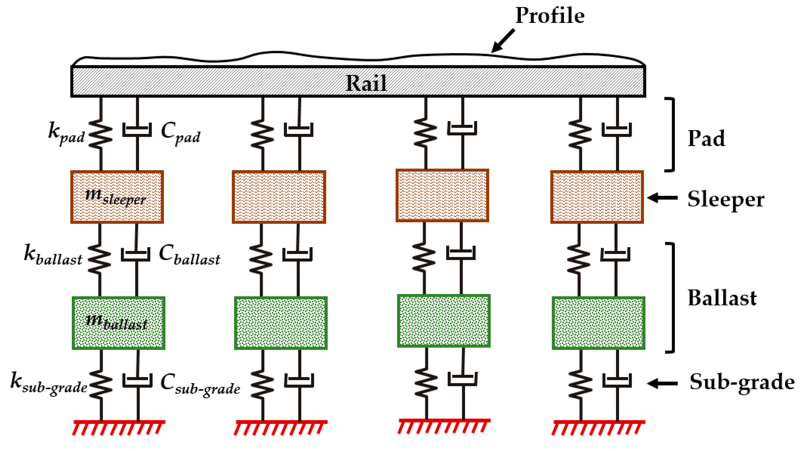
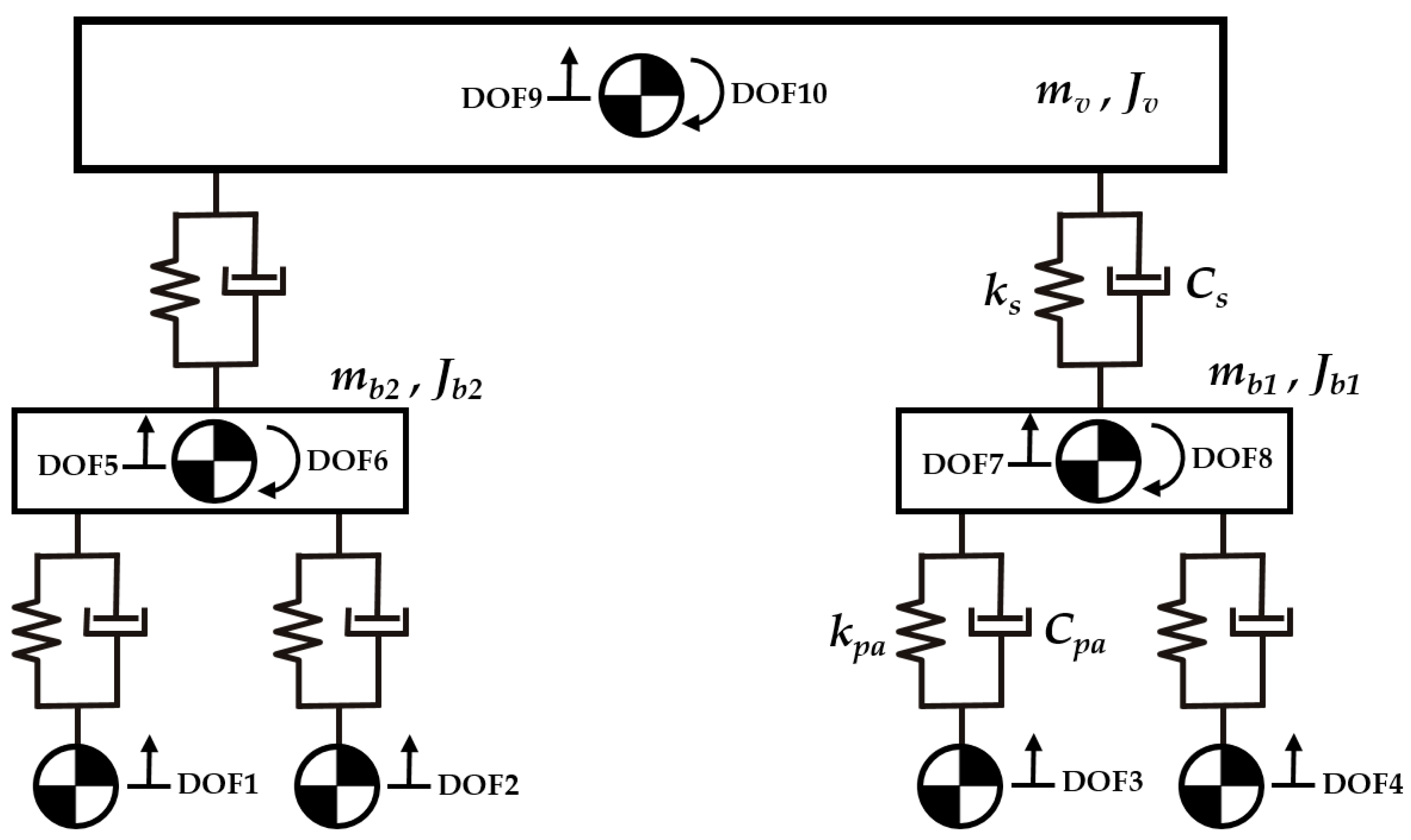
Figure 1. Directional movement under: (a) the longitudinal waves’ action, (b) the transverse waves’ action, (c) both waves’ action.
Sustainability 16 03180 g001
Figure 2. Logical modeling workflow.
Sustainability 16 03180 g002aSustainability 16 03180 g002b
Figure 3. Three-dimensional diagrams of elastic wave propagation.
Sustainability 16 03180 g003
Figure 4. Changes in the parameters of the impact of the primary impulse A 0 when falling on: (a) rectangular object, (b) triangular object.
Sustainability 16 03180 g004
Figure 5. Schematic of the coupled system.
Sustainability 16 03180 g005
Figure 6. Track numerical model.
Sustainability 16 03180 g006
Figure 7. Distribution of the sub–ballast stiffness over distance [49].
Sustainability 16 03180 g007
Figure 8. Train half-car numerical model.
Sustainability 16 03180 g008
Table 1. Input data for both modeling concepts.
Input Data
Proposed Modeling ConceptCurrent Modeling Concept
TrainTrack
Young’s modulus of materialsWheelset massElastic modulus of rail
Poisson’s ratio of materialsBogie massRail cross-sectional area
Density of materialsCar body massRail second moment of area
Geometric characteristics of elementMoment of inertia of bogieRail mass per unit length
Characteristics of primary impulseMoment of inertia of main bodyRail pad stiffness
Primary suspension stiffnessRail pad damping
Secondary suspension stiffnessSleeper mass (half)
Primary suspension dampingSleeper spacing
Secondary suspension dampingBallast stiffness
Distance between car body center
of mass and bogie pivot
Ballast damping
Distance between axlesBallast mass
Subgrade stiffness mean
Subgrade damping
Disclaimer/Publisher’s Note: The statements, opinions and data contained in all publications are solely those of the individual author(s) and contributor(s) and not of MDPI and/or the editor(s). MDPI and/or the editor(s) disclaim responsibility for any injury to people or property resulting from any ideas, methods, instructions or products referred to in the content.

