Article

Operation of a Pilot-Scale Biogas Plant Made of Textile Materials and Application of Its Results to a Full-Sized Demonstration Plant

by
Verónica Hidalgo-Sánchez
1,2,*,
Josef Hofmann
1,
María Emma Borges
2,*,
Uwe Behmel
1,
Diana Hehenberger-Risse
1,
Tobias Finsterwalder
3,
Christina Pritscher
1,
Johannes Blattenberger
1,
Tanja Wainz
1 and
Maximilian Dillis
1
1
Department of Mechanical Engineering, University of Applied Sciences Landshut, 84036 Landshut, Germany
2
Department of Chemical Engineering, University of La Laguna, 38200 La Laguna, Spain
3
Finsterwalder Umwelttechnik GmbH & Co. KG, 83233 Bernau am Chiemsee, Germany
*
Authors to whom correspondence should be addressed.
Sustainability 2024, 16(8), 3177; https://doi.org/10.3390/su16083177
Submission received: 19 February 2024 / Revised: 22 March 2024 / Accepted: 2 April 2024 / Published: 10 April 2024
(This article belongs to the Special Issue Sustainability of Bioenergy: From the Field to the Plant Production)

Abstract

:
In small German farms, there is a technically usable potential of cattle manure and pig manure ranging from 153 to 187 million tons of fresh matter per year. Since 2021 and 2023, new incentives under the Renewable Energy Sources Act (EEG) have been promoting biogas production in small farms. These incentives, applicable to biogas plants up to 150 kWel, include direct compensations for plants up to 100 kWel and market premiums for those up to 150 kWel. A small biogas plant made of textile materials was designed for both pilot and full-scale applications. Compared to conventional concrete biogas reactors, these textile-based reactors offer a simplified construction and operation, eliminating the need for specialized civil engineering. The primary objective of this research is to demonstrate the process engineering feasibility of biogas reactors based on textile materials for small farm biogas plants (30 to 75 kWel). Another goal is to design the construction method in such a way that this type of system can be built by farmers themselves after type testing on site. Operational insights were gathered from the laboratory plant with a 300-L digester volume, using cattle manure and clover grass silage. To adapt the system to the biogas reactor made of textile materials, the reactor was designed without a stirrer. These insights were considered in the design and approval procedure of the full-sized demonstration biogas plant made of textile materials. The full-size demonstration plant digesters underwent an approval procedure from local authorities, featuring treatment volumes of 120 m3 for the main biogas reactor and 550 m3 for the digestate reactor in an earth basin style. This new type of biogas plant could be built in small farms for self-sufficiency in electrical and thermal energy or for treating sewage sludge in small-scale communal wastewater treatment and biogas plants.

1. Introduction

In recent decades, governments have made efforts to reduce greenhouse gas emissions and air pollutants. Evidence of this can be seen in the international agreements known as the UN Sustainable Development Goals [1,2]. These goals have a long history dating back to the end of the last century. They have formed the foundation for various multilateral and international agreements, beginning with Agenda 21 in 1992 at the Earth Summit in Rio de Janeiro and continuing through to the present day [1]. In this context, the European Commission introduced the National Energy and Climate Plans in 2019, as part of the Clean Energy for all Europeans package [3]. European countries have set targets for achieving greenhouse gas emissions neutrality by the year 2045 [3,4]. Furthermore, since 2020, the German Renewable Energy Sources Act (EEG) has been promoting the expansion of renewable energies. Its goal is to transform the energy supply and increase the proportion of renewable energies in the electricity supply to at least 80% by 2050 [5]. The newest amendments to the EEG, namely the EEG 2020 and EEG 2023, promote biogas generation based on unused cow and pig manure in small farms [5]. Additionally, recent geopolitical events in Central Europe have highlighted the significant energy dependencies of certain countries on others. For instance, Germany’s dependency on gas from other countries has become apparent. The political and economic consequences have had a profound impact on energy prices, the energy supply and the country’s politics [6,7,8].
In Germany, there is a technically usable potential of cattle manure and pig manure ranging from 153 to 187 million tons of fresh matter per year, equivalent to an energy amount from 37.8 to 49.1 TWh [9,10]. Over 40% of this potential is located in just 35 districts, and around two-thirds of this technical potential is currently unused [11]. Additionally, 76% of the cattle farms in Bavaria and 77% of the cattle farms in Thuringia have less than 200 livestock units, so that approximately two-thirds of the technical biogas potential of these two regions, which is based in cow manure, is located in small farms [12].
The primary objective of this research is to demonstrate the process engineering feasibility of biogas reactors based on textile materials for small farm biogas plants (30 to 75 kW electrical output). Another goal is to design the construction method in such a way that this type of system can be built by farmers themselves after type testing on site. Ensuring the operational safety of the system and protecting water resources will be achieved by obtaining subsequent approval from relevant authorities or experts, in accordance with existing environmental protection regulations.
The present paper shows results from a pilot-scale biogas plant prototype and its operational variables. These results have been taken into account for the design of a full-sized biogas plant made of textile materials and its building permit for small agricultural farms. The substrates used in this project consist of agricultural residues from a small farm, including solid cattle manure from 60 large livestock units, suckler cows and fattening bulls, along with a smaller proportion of clover grass silage. Due to the farms’ organic management practices, only locally produced substrates may be used in both the pilot and the full-sized demonstration plant, which has a designed fermenter volume of approx. 120 m3. Solid manure and clover grass silage present greater challenges as substrates in biogas plants compared to liquid manure, primarily due to their high content of fiber and dry matter [13,14]. The suitability of cattle or pig manure should therefore be tested and evaluated as potential feedstock as part of the experimental operation in the 300 L pilot-scale biogas plant, which has been developed and studied.
Considering primary energy efficiency, the decentralized cogeneration of electricity and heat using combined heat and power plants (CHPs) takes precedence over central gas power plants [4]. The biogas can be stored, and the generated electricity can be on-demand and integrated into a smart grid interconnected network provided by numerous small farm biogas plants with CHPs that utilize liquid manure, manure and agricultural residues [15,16].
Furthermore, there are numerous experiments with plastic biogas reactors used for educational purposes in laboratory-scale settings [17,18] and for households and small farms with volumes under 10 m3 [19,20] in different countries around Asia, Africa and South America [20]. The applied plastic materials include fiber-reinforced plastics, soft plastics and hard plastics [20]. Soft Plastic Digesters include soft polyvinyl chloride (PVC), red mud, polymethyl methacrylate, low-density polyethylene (LDPE), polyethylene (PE) and polypropylene (PP). Hard Plastic Digesters are made from hard polyvinyl chloride (PVC), acrylonitrile butadiene styrene (ABS), polyethylene (PE), polypropylene (PP), high-density polyethylene (HDPE) and linear low-density polyethylene (LLDPE) [20]. Pilot-scale biogas plants made from textile materials still need to be investigated as a previous development step to gain experience for a full-sized demonstration biogas reactor, also made of textile materials, up to 75 kWel.

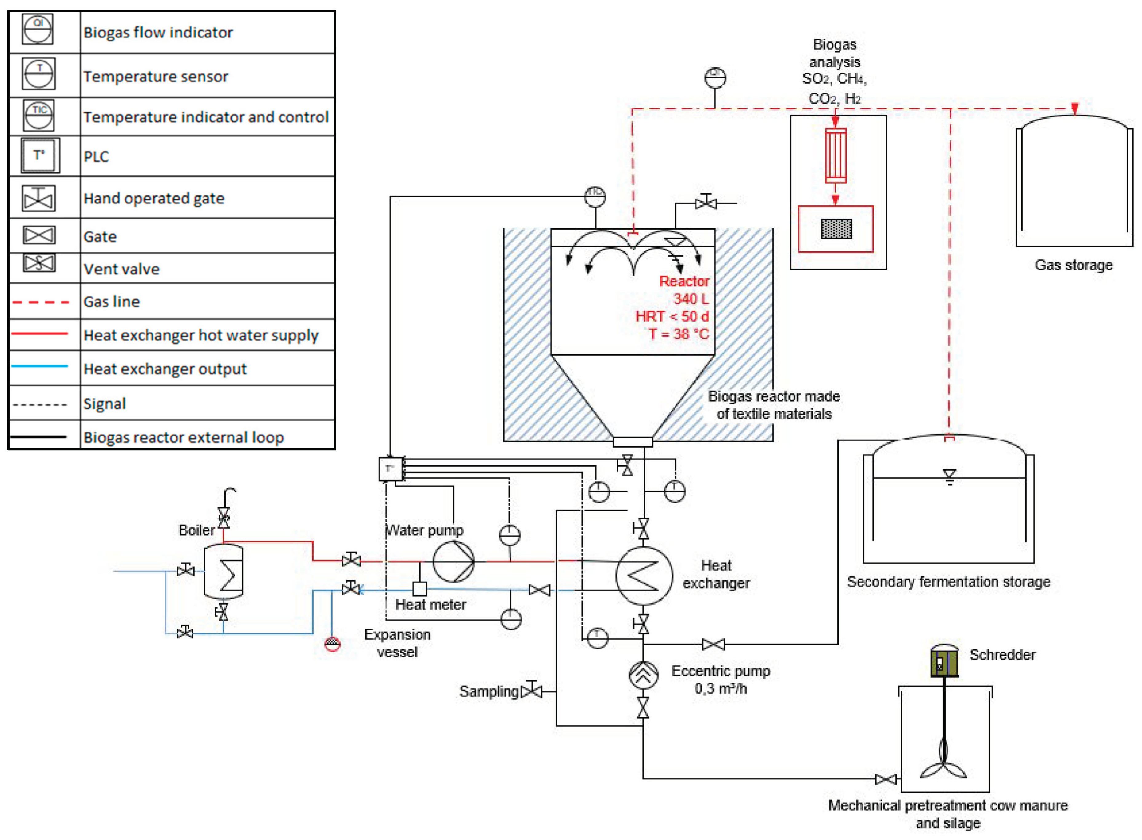
2. Materials and Methods: Pilot-Scale Biogas Plant and Full-Sized Demonstration Plant

Initially, a 300 L pilot-scale biogas plant was designed, built and operated under real environmental conditions at Landshut University’s utilities. The substrate utilized was cattle manure from 60 livestock units available on the premises and clover grass silage sourced from the cooperative farm on site. The primary objective was to gain practical experience for the second biogas reactor development phase: the design, construction and operation of a 120 m3 full-sized demonstration plant at the same location.
The textile materials intended for use in the planned biogas plant should be designed and manufactured from high-quality, quality-assured plastic films. For instance, there is a decades-long track record of successfully employing HDPE, high-density polyethylene materials, as sealing components in the construction of household waste and waste disposal landfills known as geotextiles. HDPE materials consist in general of medium-density polyethylene resin, 2.6% carbon black and an antioxidant package [21]. These geotextiles are employed to prevent the penetration of chemically aggressive leachate into groundwater-bearing layers [22,23], and there are numerous studies and investigations on the longevity and durability of HDPE geomembranes applied in civil engineering, predicting long lifetimes over 70 years in well-maintained landfills with a temperature of 33 °C [24]. Leak detection systems have also been incorporated into such landfill sealing systems to monitor the integrity of the construction materials. The applicants therefore agree that such a system should also be suitable for the construction of containers for biogas plants.

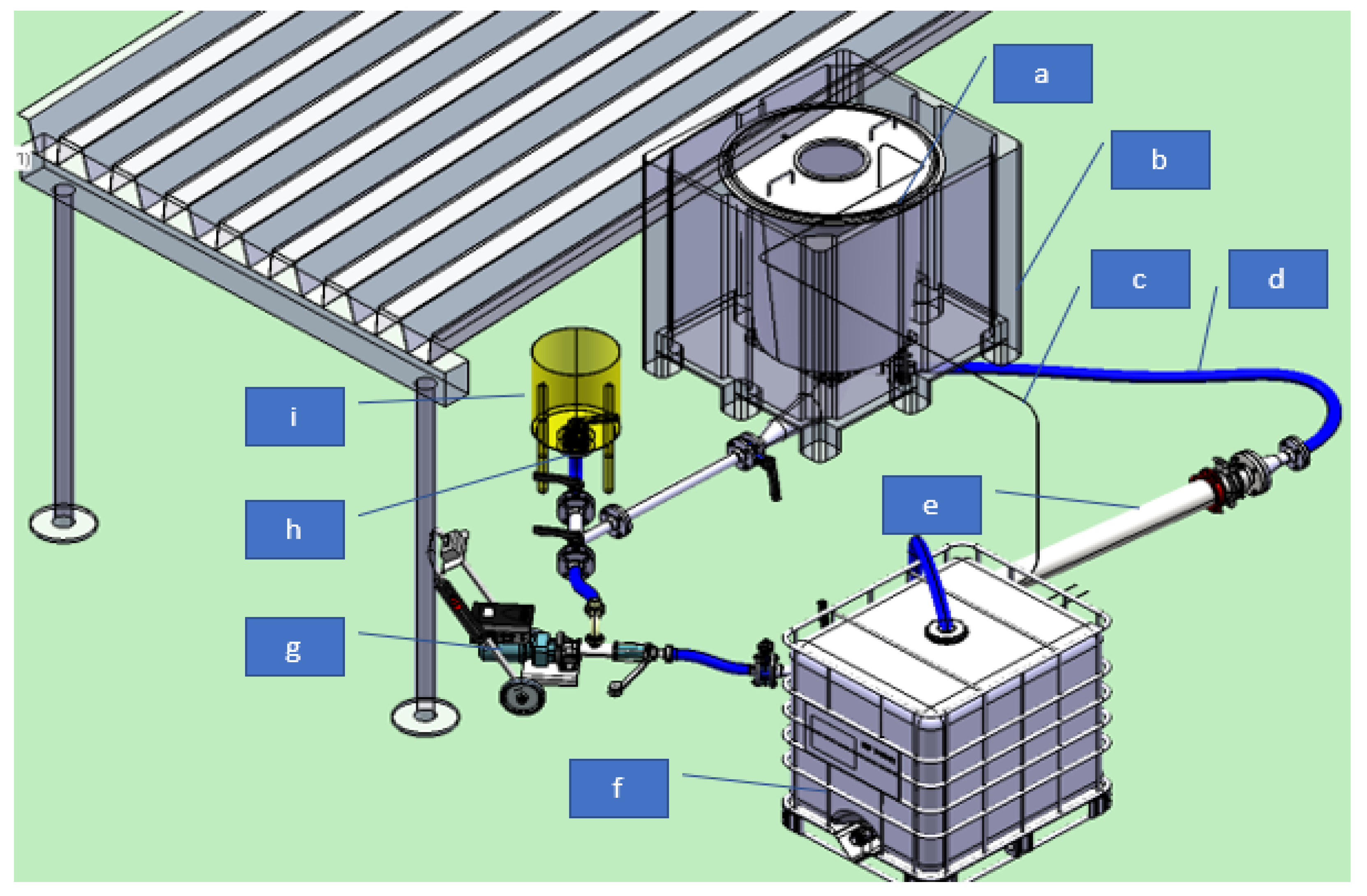
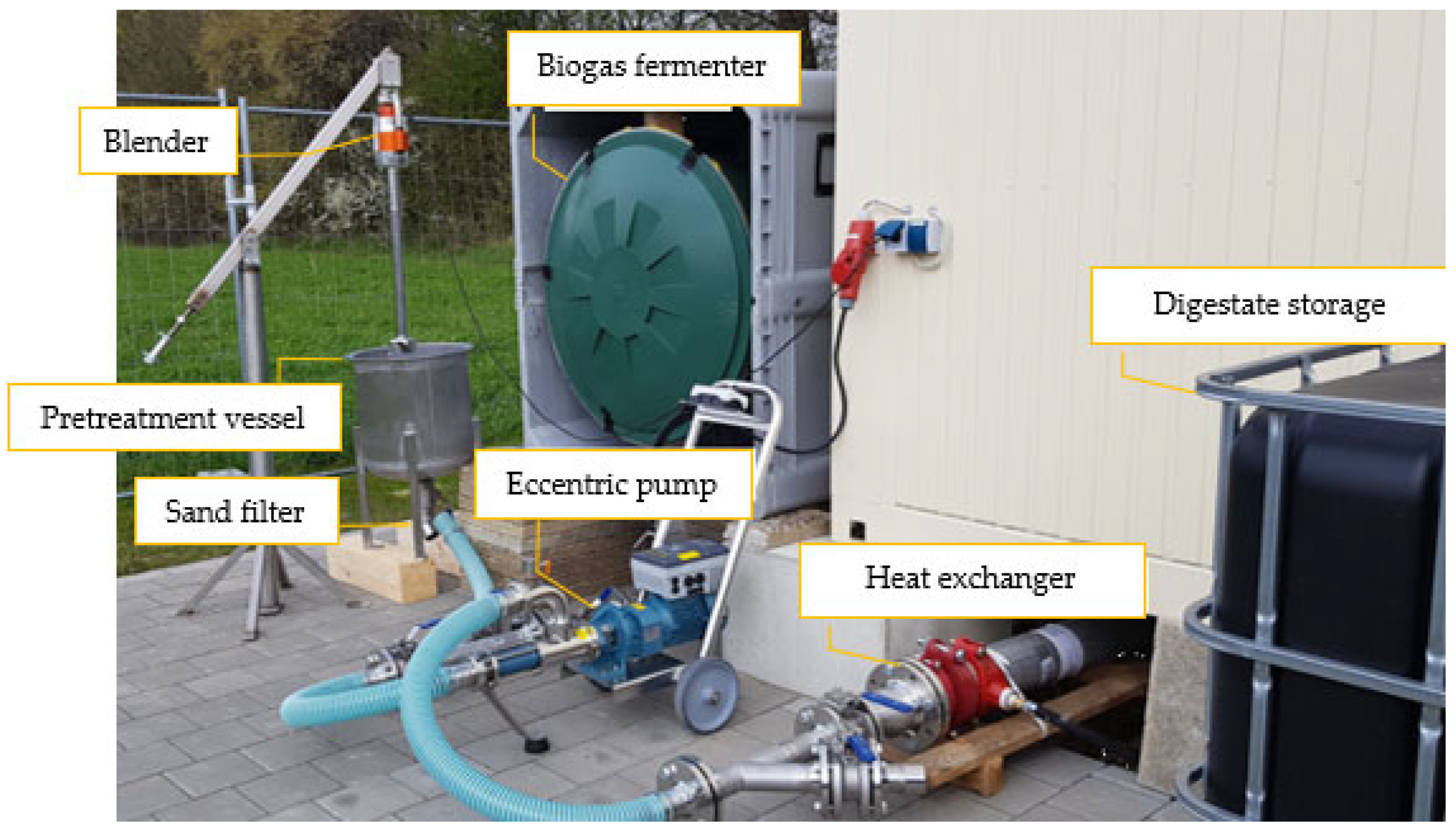
2.1. Pilot-Scale Biogas Plant Overview and Flow Diagram

The pilot biogas plant consists of the typical components found in a biogas plant. Figure 1 shows a 3D representation with the most important components of the system. This representation includes the main mechanical components referring to the substrate pretreatment, supply of the biogas fermenter and digestate storage. The pilot-scale biogas plant has a unique feature—it is designed without a stirrer, to avoid mechanical friction and potential damage to the textile material. Instead, there is an exterior circulation loop driven by an eccentric pump (g), connected by flexible hoses and stainless-steel pipes (d), which is necessary to install all the components for the heat transfer (e) and the agitation of the biogas reactor content. The biogas reactor (a) is protected and sustained by a container (b), which also serves as support for the insulation of the biogas reactor textiles. A gas pipe (c), installed at the top of the biogas reactors and connected to the digestate storage (f), collects the biogas produced. The pilot-scale biogas plant also includes a homogenization and pretreatment unit (i). This unit consists of a stainless-steel vessel connected to the exterior loop and is equipped with a sand trap (h), a ball valve and a shredder, which is attached to the pretreatment vessel. The hot water supply is connected to the pipe-in-pipe heat exchanger (e).
Figure 2 illustrates the flow diagram of the pilot-scale biogas plant with all the system components, including temperature sensors, gas measurement devices, valves and the hot water supply. The main loop input and output lines of the pilot-scale biogas plant are connected to the bottom of the fermenter. The components installed in the main loop, the eccentric pump and the heat exchanger or the fermenter itself, are equipped with cutting valves in the output and input lines, for maintenance issues. The main loop is also connected to the secondary fermentation storage, which is filled by hand, opening and closing the pertinent ball valves. The hot water flow (red line) into the system is possible though the installed pipe in the pipe heat exchanger. This hot water circuit is connected to an electrical boiler in a separated secondary water loop. There is also a tight gas line connected from the top of the biogas fermenter to the biogas storage and also to the digestate storage, which also works as additional gas storage. A sample module is connected in this line to an analyzer. A detailed description of the components follows in the subsequent sections.
Figure 3 shows the pilot-scale plant with the most important components: the biogas fermenter, the eccentric pump, the pretreatment unit with the blender and the sand filter, the heat exchanger and the digestate storage, which also acts as the secondary fermenter, which operates at ambient temperatures. The digestate storage is filled by hand, and its capacity allows it to be emptied once per year.

2.1.1. Fermenter Made of Textile Materials

The fermenter is constructed of polypropylene textile material. It is open at both the top and bottom. At the upper opening, which has an inner diameter of approx. 90 cm, it is securely attached to a cover using a flange system. This cover is connected to a bag gas hood, and the system’s tightness is ensured by a foam seal made of polypropylene. The piping connections are located at the bottom of the biogas reactor and are connected to it through a single flange in a pipe-in-pipe system. The inner connection has a 50 cm long riser tube to prevent a short-circuit flow. The fermenter consists of a plastic film made of polypropylene. To protect the film from damage, the fermenter is enclosed within a barrel that also acts as a structural support for the entire assembly, including the insulation materials. The barrel is placed within a pallet box filled with Isofloc, a material consisting of cellulose flakes obtained from paper waste, which both supports the reactor and provides insulation.

2.1.2. Mechanical Pretreatment and Homogenization: Feeding of the Pilot-Sized Biogas Plant

The substrate is fed into the system and shredded once a day within the pretreatment and homogenization vessel, along with some liquid reactor content to ensure a sufficient main dry mass in the system. Due to the presence of lignocellulosic fibers in both the cow manure and the grass silage, it is necessary to mechanically pretreat the substrate to facilitate the flow and operation of the biogas plant content [25,26]. The mechanical pretreatment ensures the cutting and defibration of the solid manure and clover grass silage. This process has a relatively low energy demand, with a peak load requirement of 1000 W. Overall, the additional energy gained per mass unit of organic matter is not always high enough to justify its use for an increased energy yield over methane. Nevertheless, efforts are underway to adapt mechanical processes for use in biogas plants [25]. In the pilot-sized biogas plant, an industrial blender, the Dynamic SMX 800 T, is employed. It is affixed to a hydrolysis and shredding vessel with a capacity of approximately 40 L.
The solid manure at the site contains several contaminants, including stones that originate from the ground where the manure is collected. These stones may also be present in the bedding material, such as the straw used for the cattle. To avoid abrasion and mechanical problems during the operation of the pilot plant, the pretreatment vessel is also equipped with a sand trap at the bottom in the feeding line between the pretreatment vessel and the main circulation loop. It consists of a piece of pipe with an outlet located halfway along its length at an angle of approximately 45°. The bottom of the pipe section is closed at the bottom with a lid that can easily be unscrewed. This design allows the stones to sink vertically, so that they are collected and then removed after the substrate is shredded and fed into the biogas plant. The shredded and homogenized substrate then flows through the sand trap into the main circuit. The flow is regulated by the opening or closing of the installed ball valves and is driven by the eccentric pump of the main circulation loop. An adequate operation of the ball valve during the feeding ensures the air-tightness of the system. This equipment requires manual operation. As the biogas plant does not have a stirrer, the eccentric pump is essential to ensure the necessary agitation in the system to promote the biogas production and to transport the heating energy into the fermenter.

2.1.3. Piping

The main pipelines are constructed from stainless-steel pipes with a nominal diameter of DN 50. Additionally, DN 50 flexible, thin plastic hoses have been installed for ease of removal during maintenance and for visual circuit monitoring. The flaps and T-pieces are made from stainless steel. To facilitate access in case of solid accumulations in the loop, the hoses are connected to the pump through easily detachable pipe fittings. The piping is insulated with a 50 mm layer of rockwool and a special aluminium covering sheet to protect it from atmospheric conditions.

2.1.4. Digestate Storage

A secondary container with a capacity of 1000 L serves as secondary storage for the digestate until its application in the field. This container is gas-tight and can therefore also be used as a gas storage facility. This design contributes to extending the substrate retention time under ambient temperature. Both the primary digester and the digestate storage are connected to the biogas storage though a gas pipe.

2.1.5. Heating System, Temperature Control and Regulation

To maintain a constant temperature of 37 °C in the biogas reactor and ensure mesophilic operation, a hot water supply, a temperature control unit and sensors are essential. These sensors, in connection with the control unit, regulate the hot water supply and the temperature in the biogas reactor and the external loop. Standard calibrated two-wire PT100 temperature sensors are employed for this purpose and are connected to a Prozeda grandis 650HK control and regulation unit.
Since the laboratory biogas plant cannot be connected to an existing heating infrastructure, the heat source utilized is an electrical hot water boiler. This boiler has a maximum temperature of 70 °C and its own control temperature. As a result, the temperature can be adjusted to maintain the design operational temperature in the biogas reactor for mesophilic conditions. This requires a hot water supply typically between 50 and 55 °C in winter and 45 °C in summer. The heat is supplied via an additional water loop, and heat transfer occurs within a double tube heat exchanger provided by FiTeC Umwelttechnik GmbH & Co. KG (Bernau am Chiemsee, Germany). The control unit receives temperature readings from the sensors installed in the biogas reactor, as well as in the inlet and outlet lines of the reactor, the inlet and outlet lines of the heat exchanger and the hot water loop. If the temperature of the biogas reactor drops below 35 °C, the control unit activates the hot water pump to supply the heat exchanger with hot water, which is connected to the external biogas reactor loop, thus heating the biogas reactor loop. The eccentric pump operates continuously, as it transfers heat to the biogas reactor, and the content also has to be mixed to allow a good anaerobic fermentation and to avoid the accumulation of solids in unfavorable places.

2.1.6. Gas Measurement and Analysis

The volume flow is measured using a TG 1/5 drum gas meter from Ritter with a measuring range of 2–120 L/h and uses water as a pressure barrier. Gas composition analysis is carried out by a mobile gas measuring device, the Multitec 540 from Sewerin (Gütersloh, Germany). This device is equipped with sensors for measuring methane, carbon dioxide, hydrogen, oxygen and sulfide. Periodic calibration is performed using a test gas mixture that closely resembles the expected biogas composition. For connecting the mobile Multitec 540, a permanently mounted connection is available, which includes a gas cooler, a condensate trap and a particle filter.

2.1.7. Laboratory Measurements

The parameters analyzed for the substrate characterization adhere to the guideline of the Association of German Engineers (VDI) 4630: Fermentation of organic substances -Substrate characterization, sampling, substance data collection. Table 1 provides a list of the measured parameters and the corresponding laboratory equipment.

2.2. Inoculum

The inoculum is a solid suspension containing microorganisms that carry out the anaerobic degradation processes. In this project, the inoculum is obtained from the digestate of an agricultural biogas plant where solid manure and energy corn are processed. Different inoculum samples from the same digestate storage plant show activity and composition variations, especially in their residual organic acid content. This is due to fluctuations in the operational management of the biogas plant, the substrates and co-substrates used, and their seasonal variations.

2.3. Substrate

Cattle manure and clover grass are the two types of substrate available on site. After harvesting, the clover grass is stored for a minimum of 6 months before it is fed to the cattle. However, the availability of clover grass silage is limited since it primarily serves as feed for the cattle on site. Consequently, only the surplus feed can be utilized as a co-substrate. The most important requirement for EEG remuneration is the proportion of manure in the total substrate, which must be at least 80%, with a hydraulic retention time in the gas-tight system of at least 150 days [5]. This retention time is made possible by the secondary storage reactor, which operates at ambient temperatures, allowing for additional fermentation. Since a maximum of 20% co-substrate is permitted without compromising the intended use as agricultural fertilizer, these mass proportions have been considered for the experiment.

3. Results from the Pilot-Scale Plant

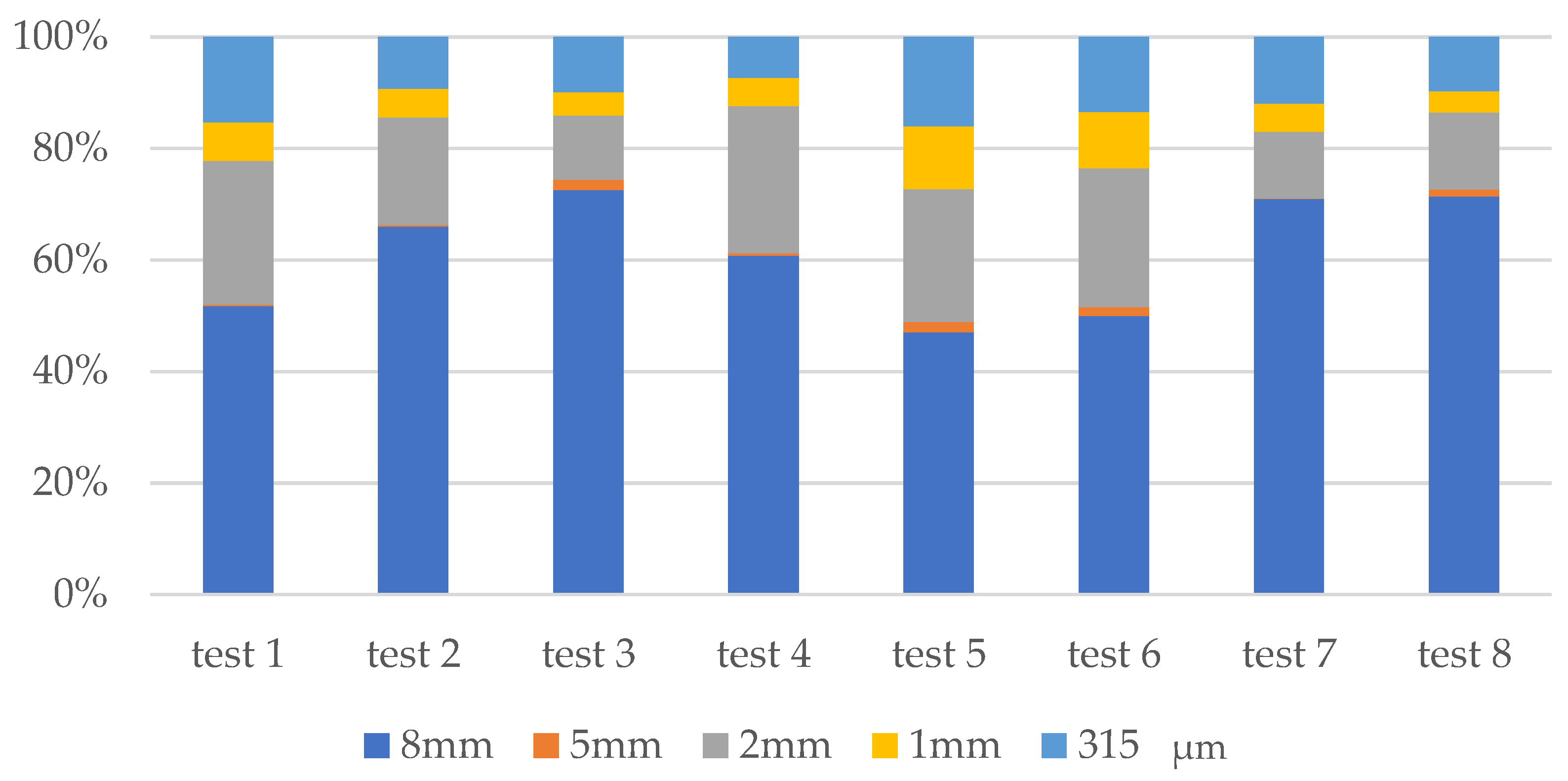
3.1. Mechanical Pretreatment

3.1.1. Mechanical Pretreatment Duration and Particle Size

To optimize the pretreatment duration and energy input, an experiment was conducted in the 40 L pretreatment vessel by combining two different substrate loadings, two different water volumes and two different shredding times. The initial parameters of the experiment procedures are presented in Table 2.
Figure 4 illustrates that the combination in Test 5 yielded the best results, with 10 L/0.88 kg/140 s, achieving an over 50% reduction in fiber size to under 5 mm, with a specific energy input of 44.4 Wh/kg substrate. Test 6 showed similar results using 20 L of water instead of 10 L, and Test 1, with a shredding time of 100 s instead of 140 s, resulted in a lower specific energy input of 31.7 kWh/kg of substrate. The sieve analysis was carried out by a sieve shaker AS 200 control from Retsch (Haan, Germany).
The best energy efficiency was achieved in Test 4, which used parameters of 20 L/1.75 kg/100 s and resulted in acceptable shredding, as the particle deflection was at 5 mm, not at 8 mm. The parameters from Test 4 were chosen to feed the pilot-scale biogas plant, favoring the efficiency of the process with at least 40% of the particles being under 5 mm.

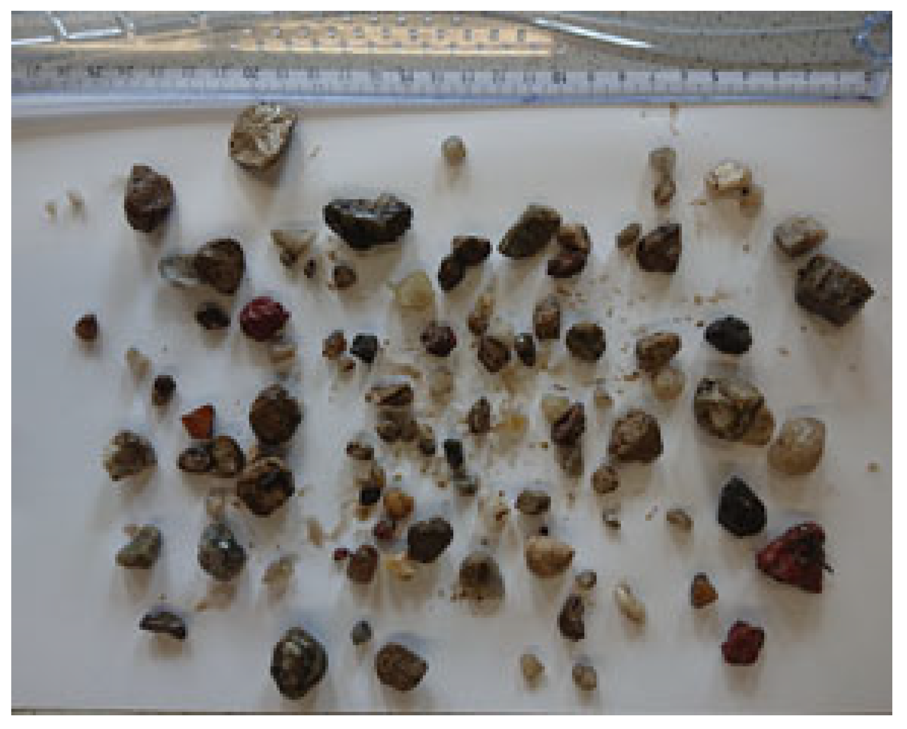
3.1.2. Sand and Stones Trap

The straw is sourced from the farm’s soil, which has a gravelly composition. The stones can cause significant problems, particularly during the dosing of the solid manure suspension into the fermenter. The stator of the eccentric screw pump, which is made of nitrile butadiene rubber, is prone to abrasion, leading to pump failures on several occasions. The stones are obviously introduced into the feeding line due to the high flow forces during the crushing process. Figure 5 shows the stones and sand collected over one month of regular operation. The collected sand and stones made up to 1% of the input substrate mass.

3.2. Operation of the Pilot-Scale Biogas Plant

3.2.1. Starting the Biogas Operation

During the start-up process in summer, significant pH increases were observed in the stored solid manure (up to 9.3) due to the high temperatures. This also quickly led to a pH rise to 8.15 in the fermenter. Analytical data revealed ammonium concentrations of up to 1.3 g/L, leading to an inhibition caused by free ammonia. At a pH of 8.15, approximately 10% of the ammonium is present as free ammonia. While this might not be a concern in stable biogas plants, during the experiment, it significantly inhibited gas production. The pH value was too high for rapid hydrolysis and acidification. It was demonstrated that only solid manure was suitable for the start-up process in its fresh form. After activating the microorganisms, the substrate dosage initially consisted of solid manure, with a DM between 17.1% and 21.5% and an oDM from 82% to 84%, and after regular operation, the manure was combined with clover grass silage as a co-substrate, with a DM of 1.8% and an oDM of 79.4%.

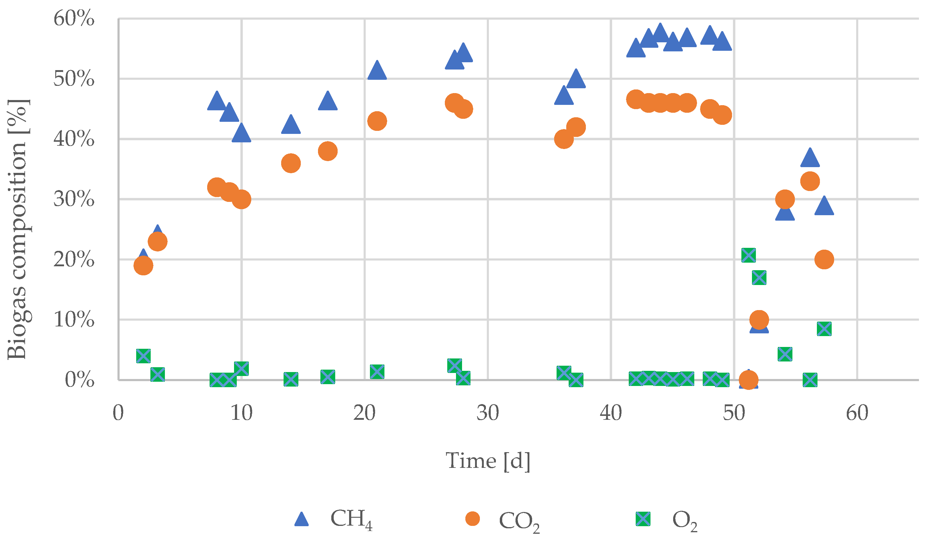
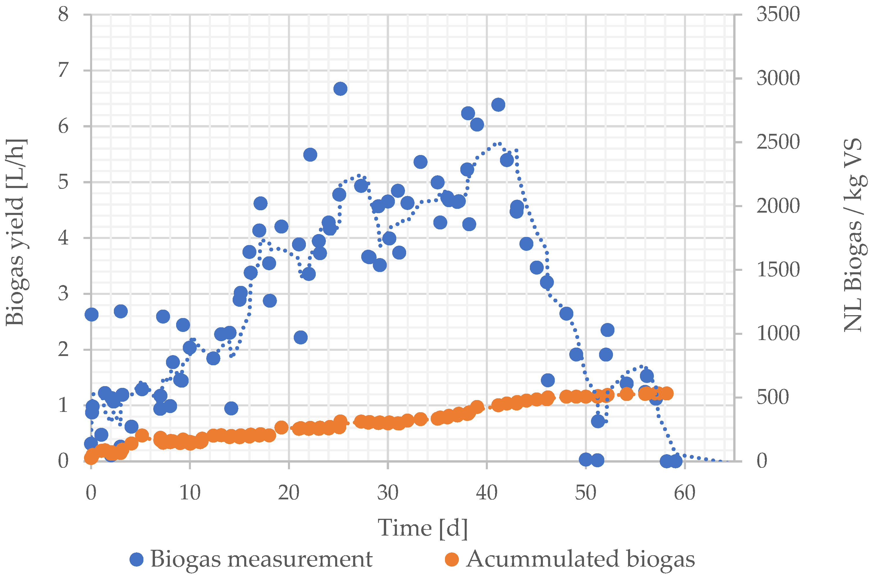
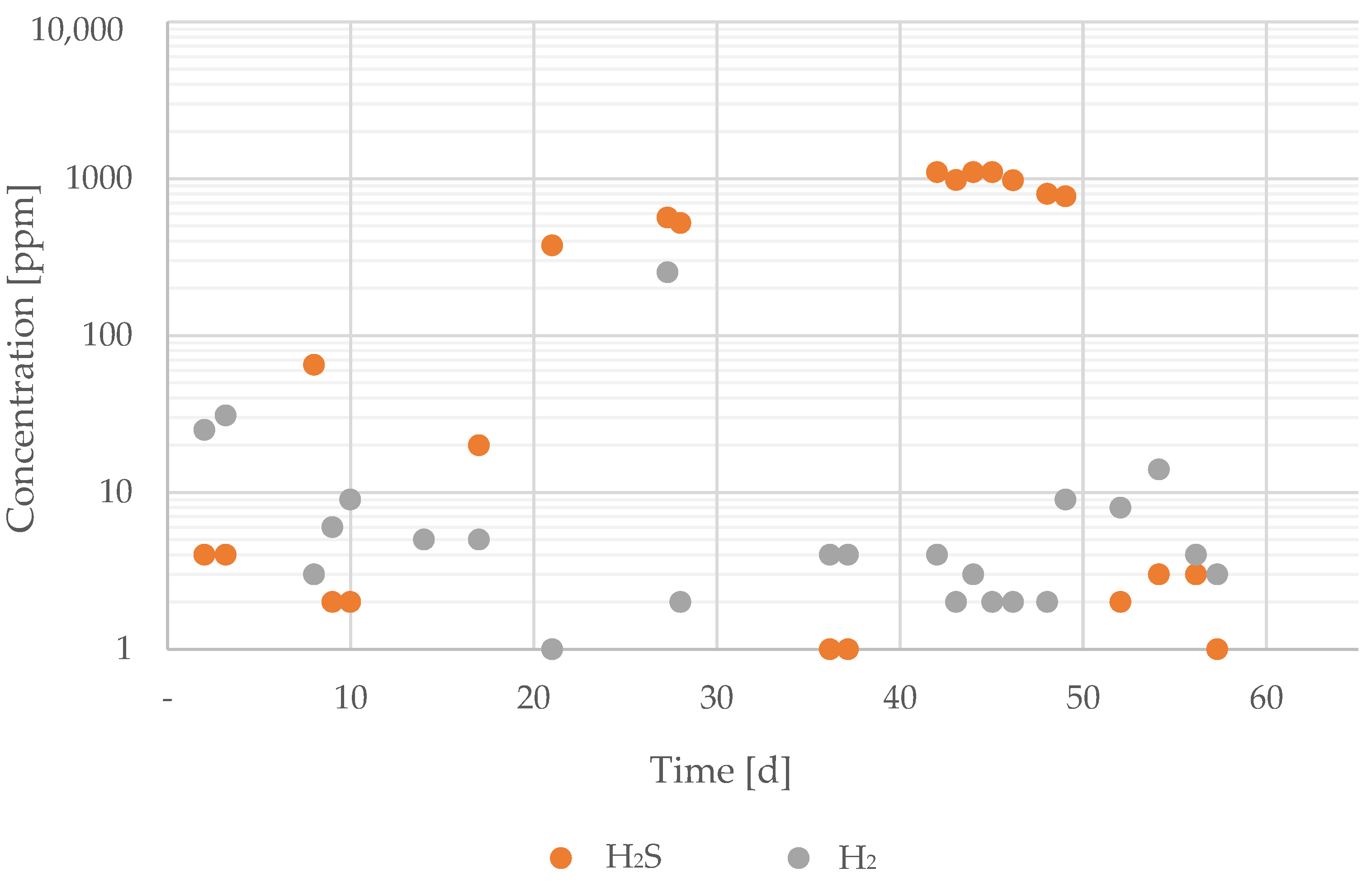
3.2.2. Biogas Yield and Composition

Figure 6 shows the gas yield during normal operation; it increased continuously and stabilized around an average of 5 L/h from test day 20. The methane content ranged between 50 and 55%, as shown in Figure 7. The total amount of gas produced during regular operation up to test day 58 added up to a gas yield of 4235 L = 533 L/kg OTS (71.2 m3/t FM).
After two days of normal operation, the biogas was composed of 20.2% of CH4, 23% of CO2, 4 ppm H2S, 25 ppm CO, 4% O2 and 15% N2. This biogas composition varied fast, and it adjusted after 8 days to 46.4% of CH4, 32% of CO2, 65 ppm H2S, 3 ppm CO, 0% O2 and 0% N2. From test day 21, the biogas yield was composed of 51.5% of CH4, 43.0% of CO2. 376 ppm H2S, 1 ppm CO, 1.4% O2 and 5.3% N2 (Figure 7).
The biogas also contained traces of other gases, such as hydrogen sulfide, which varied greatly. Figure 8 illustrates the concentration of trace gases. The hydrogen sulfide concentration decreased, particularly when solid manure and co-substrate were added during normal daily operation. However, when the regular operation was interrupted, preventing the daily feeding of the biogas plant, no oxygen was introduced into the fermenter. As a result, the hydrogen sulfide could not be oxidized, which caused peak concentrations of hydrogen sulfide.

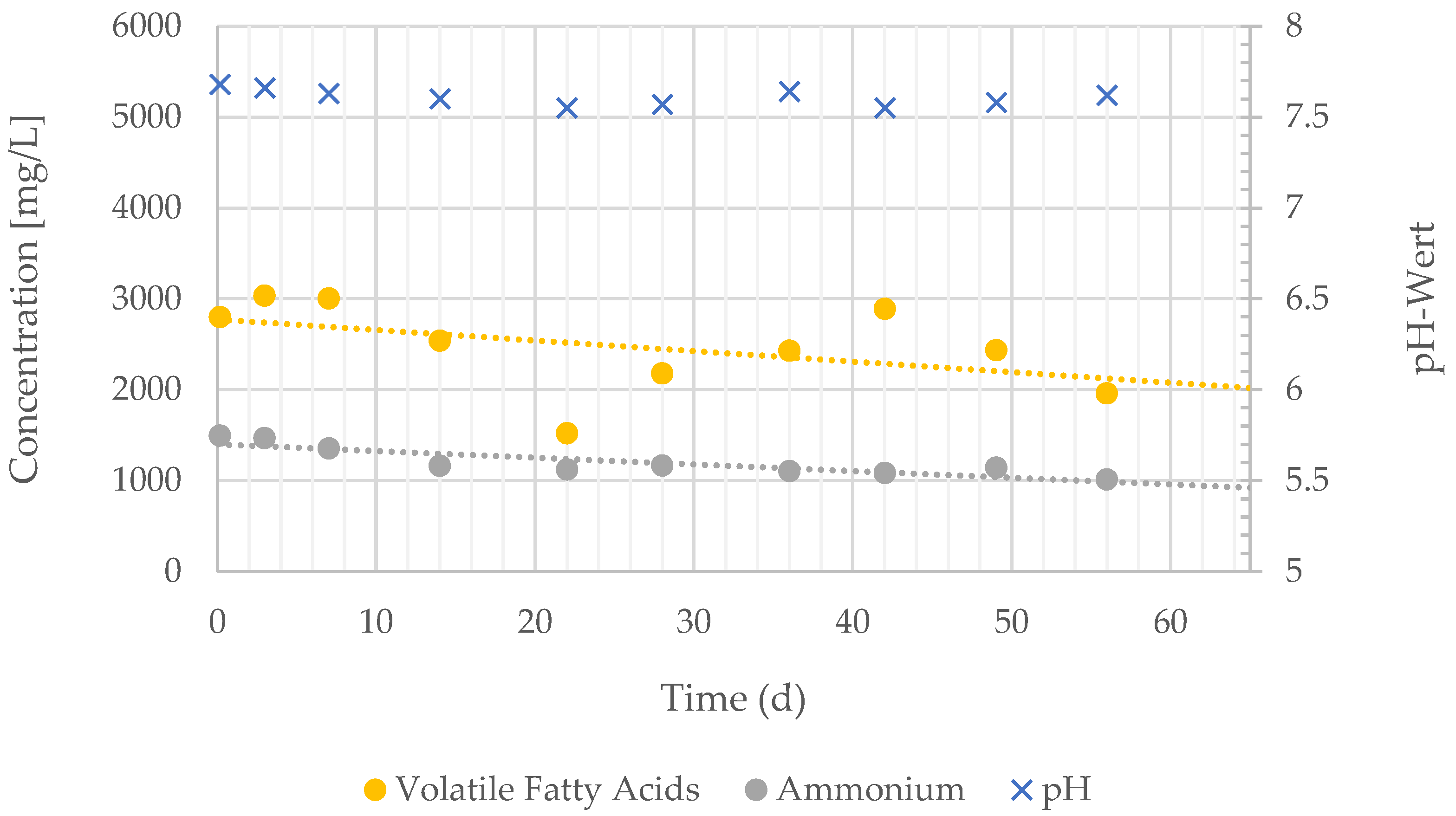
3.2.3. pH, Ammonium and Volatile Fatty Acids

During the normal operation phase, there was an increase in organic acids from approximately 1500 mg/L to nearly 3000 mg/L. However, as no significant hydrogen peaks were detected and the pH value did not change significantly, it can be assumed that the selected load is far from reaching its maximum capacity. Figure 9 shows the analyzed chemical parameters during normal operation.
The ammonium concentration decreased from about 1500 mg/L to 1050 mg/L. This reduction can be attributed to the fact that the ammonium concentration of the inoculum was higher than in the solid manure, leading to the breakdown of the initial concentration.

3.2.4. Floating Layer

No agitator was used to operate the fermenter. However, the floating layer gradually became more impermeable to the biogas. During the test, a dense floating layer developed, restricting the escape of gas. To facilitate the release of gas from the reactor content, it is necessary to periodically disrupt and moisten the floating layer with substrate. A thick floating layer was removed on test day 50.

3.3. Improvements during Operation

Stirrer and Substrate Floating Layer

To minimize the risk of damage and additional components in the textile reactor, the fermenter was initially constructed without a stirrer. Instead, it was intended to maintain the substrate circulation solely by the external circulation pump.
However, it turned out that a stirrer is essential for regularly disrupting the floating layer without the need to open the lid. The requirements for this stirrer included ensuring that neither the lance nor the temperature sensor, which hangs from the lid in the fermenter, would be damaged. Consequently, a lifting stirrer was selected. This type of stirrer does not rotate; instead, it achieves mixing through an up and down movement of a perforated disc.

3.4. Transfer to the Design of the Full-Sized Demonstration Biogas Plant

3.4.1. Stirrer

There are already liquid manure biogas plants that operate without a stirrer, so the main hydraulic circulation of the textile fermenter was designed to be sufficient for agitating the biogas substrate. As a result of the experience gained from the floating layer in the pilot-size fermenter, an agitator will be incorporated into the design of the full-scale demonstration plant.

3.4.2. Pretreatment

The shredding used in the pilot plant cannot be replicated identically in the demonstration plant. It is not possible to obtain a motor with explosion protection for the blender. This precaution is necessary because when solid manure is crushed in fermenter liquid, the release of methane cannot be prevented and a potential explosion cannot be reliably ruled out. Therefore, the company Finsterwalder Umwelttechnik GmbH & Co. KG has developed a process based on high blade speeds with which the explosion protection requirements can be met.

3.4.3. Institutional Permissions

There are numerous legal requirements to consider during the design and construction of the on-site biogas demonstration plant [27,28,29]. To begin with, the construction employs textile materials, which are not typically used in biogas plant construction. Secondly, these legal requirements are not solely dependent on the characteristics of the biogas plant and its substrates but also on its location. In this specific case, the farm where the on-site demonstration biogas plant will be built is close to the floodplain of the Schweinsbach Creek, necessitating compliance with particular requirements [30]. The most important special aspects of this unique case are explained in the following section.

Requirements for Biogas Reactor

To ensure compliance with regulations, the lowest point of the fermenter, specifically the underside of the insulation, must be situated at least 50 cm above the groundwater level [30,31]. Furthermore, the use of textile material for the fermenter is a novel application and not a standard solution. The suitability of the textile material for this application must be proven through a report issued by an authorized technical expert [30]. If the textile material already has a National Technical Approval (abZ) or a General Construction Technique Permit (aBG) for manure soil basins, any deviations from the abZ/aBG must be meticulously assessed, including the design, the gradient toward the control pipe, the integration of the extraction pipeline, the protective cover of the fermenter base, the agitator and more.

Requirements for Leakage Detection in the Digestate Storage and Piping System

The visual leak detection of the digestate storage can be compromised by rainwater. To eliminate potential confusion arising from the differing conductivities of water and digestate, the possibility of employing conductivity measurement is being considered. The proposed approach involves utilizing a single-walled pipe within a protective tube, requiring the implementation of leakage detection through an inspection shaft [32].

General Requirements

The approvals for the individual components must conform to the relevant legislation stipulated by the Bavarian Environment Agency [29]. Safety devices are mandatory for the transfer of digestate to transport vehicles for distribution. The construction of the biogas plant must be carried out by a specialist company in accordance with the Ordinance on Facilities Handling Substances that are Hazardous to Water (AwSV) and subsequently approved by an expert in compliance with AwSV. The filling point for the digestate must meet the requirements of the technical rules for water-hazardous substances (TRwS) [32]. A detailed description of the implementation process is also required.

4. Discussion

Small-scale biogas plants constructed from textile materials have proven to be effective in generating biogas using the available on-site substrates. This innovative construction approach aimed to enable the easy installation of biogas reactors on site without the need for concrete structures or specialized civil engineering work. The functionality of this new concept was successfully demonstrated in the 300 L pilot-size plant. Various components, such as shredding pretreatment, a stone separator and an exterior circulation loop for mixing without a stirrer, were incorporated to adapt the substrate to the biogas plant’s operating conditions. The biogas yield achieved in the laboratory plant was close to the optimal theoretical biogas yields according to literature data of the Bavarian Agriculture Institute [10]. However, when upscaling to larger sizes, certain modifications were required not only to accommodate different product sizes and upscaling but also to meet the regulatory requirements for biogas plant permits. The decision-making process for determining the necessary technical requirements was a lengthy and complicated one, involving local authorities and technicians who needed to approve the system initially. This process can influence the acceptance of new developments and implementations according to the current political and energy landscape.
The construction of conventional biogas reactors primarily requires materials such as concrete, asphalt, steel and brick, which make up approximately 50% of the investment costs [14]. This conventional construction method contributes to approximately 15% of the equivalent CO2 emissions from conventional biogas reactors, without considering the benefits of applying cogeneration [33]. Presently, small agricultural farms, with livestock units ranging from 50 to 60 livestock units, are not able to operate biogas plants economically due to the high investment costs, which range between 5000 EUR and 4000 EUR per kWel for cow and pig manure biogas reactors between 100 kWel and 1 MWel [14,34]. Textile biogas reactors should increase the economic viability of biogas plants for small producers like livestock farms or small towns. This cost reduction will enable these plants to operate economically.

5. Conclusions

-
The operation of a 300 L pilot-size biogas reactor, constructed using textile materials and utilizing cow manure with silage as a co-substrate, was successfully demonstrated. The biogas yields and composition were comparable to those of standard biogas plants constructed with concrete and reinforced steel.
-
The pilot-size biogas plant was equipped with a pretreatment unit for shredding, separating impurities and homogenizing the substrate. The removal of interfering materials, such as stones or sand, which made up to 1% of the substrate mass input, was crucial for the proper operation of the biogas plant. Stones could damage the plastic sheet. This must be avoided to prevent groundwater pollution.
-
To prevent mechanical damage of the plastic sheet, the biogas plant was designed and constructed without a stirrer. During normal operation, however, a thick floating layer accumulated, mainly composed of lignocellulosic materials. To ensure proper biogas production, the periodic disruption of the floating layer and accumulated materials is essential.
-
The process of obtaining institutional permissions for this new product was lengthy, spanning over two years. Such extended procedures can impact the acceptance of new developments and implementations within the current political and energy landscape.
-
Further investigation is needed for other substrates, as only cattle manure with clover grass, with a high content of lignocelluloses, was the object of this study. Substrates with a high proportion of fatty acids and their consequences on the process were not investigated.
-
The investigation of the disruptive materials contained in the substrates is also an important path to consider, as they can have a significant impact on the materials’ lifetime, maintenance cycles and their consequent economic impact.

Author Contributions

V.H.-S. contributed to this study´s conceptualization, methodology, validation, formal analysis, investigation, data curation, writing, draft preparation and editing. J.H. contributed to this study´s conceptualization, review, supervision, project administration and funding acquisition. M.E.B. contributed to this study´s conceptualization, methodology, validation and writing—review and editing. U.B. contributed to this study´s validation, investigation, resources, review, supervision and project administration. D.H.-R. contributed to this study´s conceptualization, investigation and project administration. T.F. contributed to the resources and to the conceptualization. C.P. contributed to the data curation. J.B. contributed to the visualization and resources. T.W. contributed to the English review, and M.D. contributed to the methodology. All authors have read and agreed to the published version of the manuscript.

Funding

This research was funded by the Bavarian Ministry for Economic Affairs, Research and Development Project “Small biogas plants made of textile materials BGA-Textil-BE/19/02”.

Informed Consent Statement

Not applicable.

Data Availability Statement

The data that support this study are available on request.

Acknowledgments

We wish to thank the whole Department of Mechanical Engineering of the University of Applied Sciences in Landshut and especially Walter Fischer for his contributions to the investigation project; Donata Huber, Daniel Chirita and Sophie Schneider for their cooperation during the whole project in the laboratory works and during the pilot-scale plant operation; and the Department of Chemical Engineering at La Laguna University. Many thanks to the Agricultural Machinery School, especially to Wiedemann.

Conflicts of Interest

Author Tobias Finsterwalder was employed by the company Finsterwalder Umwelttechnik GmbH & Co. KG. The remaining authors declare that the research was conducted in the absence of any commercial or financial relationships that could be construed as a potential conflict of interest.

References

  1. THE 17 GOALS|Sustainable Development. Available online: https://sdgs.un.org/goals#icons (accessed on 26 November 2023).
  2. United Nations—General Assembly. Resolution Adopted by the General Assembly on 25 September 2015: Transforming Our World: The 2030 Agenda for Sustainable Development; United Nations: New York, NY, USA, 2015. [Google Scholar]
  3. European Commission. Regulation (EU) 2018/1999 of the European Parliament and of the Council of 11 December 2018 on the Governance of the Energy Union and Climate Action, amending Regulations (EC) No 663/2009 and (EC) No 715/2009 of the European Parliament and of the Council, Directives 94/22/EC, 98/70/EC, 2009/31/EC, 2009/73/EC, 2010/31/EU, 2012/27/EU and 2013/30/EU of the European Parliament and of the Council, Council Directives 2009/119/EC and (EU) 2015/652 and repealing Regulation (EU) No 525/2013 of the European Parliament and of the Council (Text with EEA relevance.): Document 32018R1999. 2023. Available online: https://eur-lex.europa.eu/legal-content/EN/TXT/PDF/?uri=CELEX:32018R1999&from=EN (accessed on 18 February 2024).
  4. Bundesministerium Für Energie und Wirtschaft. Integrierter Nationaler Energie- und Klimaplan gemäß der VERORDNUNG DES EUROPÄISCHEN PARLAMENTS UND DES RATES über das Governance-System für die Energieunion und für den Klimaschutz, zur Änderung der Richtlinie 94/22/EG, der Richtlinie 98/70/EG, der Richtlinie 2009/31/EG, der Verordnung (EG) Nr. 663/2009, der Verordnung (EG) Nr. 715/2009, der Richtlinie 2009/73/EG, der Richtlinie 2009/119/EG des Rates, der Richtlinie 2010/31/EU, der Richtlinie 2012/27/EU, der Richtlinie 2013/30/EU und der Richtlinie (EU) 2015/652 des Rates und zur Aufhebung der Verordnung (EU) Nr. 525/2013: Integrierter Nationaler Energie- und Klimaplan. 2020. Available online: https://www.bmwk.de/Redaktion/DE/Downloads/I/integrierter-nationaler-energie-klimaplan.pdf?__blob=publicationFile&v=8 (accessed on 18 February 2024).
  5. Bundesministerium Der Justiz. Gesetz Für Den Ausbau Erneuerbarer Energien (Erneuerbare-Energien-Gesetz—EEG 2023); Bundesministerium Der Justiz: Berlin, Germany, 2014. [Google Scholar]
  6. Grabau, M. Gas Games: Der Wandel Der Europäischen Erdgasaußenpolitik Infolge Der Ukraine-Krise; Vieweg: Wiesbaden, Germany, 2017; ISBN 9783658201555. [Google Scholar]
  7. Grimm, V.; Groß, C.; Marxsen, T.; Schwarz, M. Energiekrise Belastet Haushalte. Wirtschaftsdienst 2023, 2023, 754–761. [Google Scholar] [CrossRef]
  8. Holtemöller, O.; Kooths, S.; Schmidt, T.; Wollmershäuser, T. Gemeinschaftsdiagnose: Energiekrise, Inflation, Rezession und Wohlstandsverlust. Wirtschaftsdienst 2022, 2022, 761–765. [Google Scholar] [CrossRef]
  9. Fachagentur Nachwachsende Rohstoffe e.V. FNR. Faustzahlen. Available online: https://biogas.fnr.de/daten-und-fakten/faustzahlen (accessed on 18 February 2024).
  10. Bayrische Landesanstalt Für Landwirtschaft. Biogasausbeuten Verschiedener Substrate. Available online: https://www.lfl.bayern.de/iba/energie/049711/?sel_list=51%2Cl&anker0=substratanker#substratanker (accessed on 14 December 2023).
  11. Majer, S.; Kornatz, P.; Daniel-Gromke, J.; Rensberg, N.; Brosowski, A.; Oehmichen, K.; Liebetrau, J. (Eds.) Stand und Perspektiven Der Biogaserzeugung Aus Gülle; Deutsches Biomasseforschungszentrum Gemeinnützige GmbH: Leipzig, Germany, 2019; ISBN 9783946629481. [Google Scholar]
  12. Effenberger, M. Personal Communication; Bavarian State Research Center for Agriculture: Freising, Germany, 2023. [Google Scholar]
  13. Croce, S.; Wei, Q.; D’Imporzano, G.; Dong, R.; Adani, F. Anaerobic digestion of straw and corn stover: The effect of biological process optimization and pre-treatment on total bio-methane yield and energy performance. Biotechnol. Adv. 2016, 34, 1289–1304. [Google Scholar] [CrossRef] [PubMed]
  14. Biogasinitiative Der Brandenburgischen Energie Technologie Initiative. Biogas in Der Landwirtschaft: Leitfaden Für Landwirte und Investoren im Land Brandenburg; Biogasinitiative Der Brandenburgischen Energie Technologie Initiative: Postdam, Germany, 2006. [Google Scholar]
  15. Persson, T.; Murphy, J.; Jannasch, A.-K.; Ahern, E.; Liebetrau, J. A Perspective on the Potential Role of Biogas in Smart Energy Grids; IEA Bioenergy: Paris, France, 2014; ISBN 9781910154137. [Google Scholar]
  16. Bayerische Landesanstalt Für Landwirtschaft. Abschlussbericht Zum Vorhaben: Einrichtung und Erprobung Des Intervallbetriebs Der Biogasanlage an Der Versuchsstation Grub (N/14/13); Projektbericht: Grub, Germany, 2018. [Google Scholar]
  17. Vogel, F.W.; Carlotto, N.; Wang, Z.; González-Herrero, R.; Giménez, J.B.; Seco, A.; Porcar, M. Simplicity Hits the Gas: A Robust, DIY Biogas Reactor Holds Potential in Research and Education in Bioeconomy. Fermentation 2023, 9, 845. [Google Scholar] [CrossRef]
  18. Yimer, S.; Yimer, B.; Sahu, O. Biogas Production Using Geomembrane Plastic Digesters as Alternative Rural Energy Source and Soil Fertility Management. Sustain. Energy 2014, 2, 12–19. [Google Scholar] [CrossRef]
  19. Garfí, M.; Castro, L.; Montero, N.; Escalante, H.; Ferrer, I. Evaluating environmental benefits of low-cost biogas digesters in small-scale farms in Colombia: A life cycle assessment. Bioresour. Technol. 2019, 274, 541–548. [Google Scholar] [CrossRef] [PubMed]
  20. Cheng, S.; Li, Z.; Mang, H.-P.; Huba, E.-M. A review of prefabricated biogas digesters in China. Renew. Sustain. Energy Rev. 2013, 28, 738–748. [Google Scholar] [CrossRef]
  21. Jeon, H.-Y.; Bouazza, A.; Lee, K.-Y. Depletion of antioxidants from an HDPE geomembrane upon exposure to acidic and alkaline solutions. Polym. Test. 2008, 27, 434–440. [Google Scholar] [CrossRef]
  22. Kerry, R.; Rowe, H.P. Durability of HDPE geomembranes: Review Article. Geotext. Geomembr. 2002, 20, 77–95. [Google Scholar]
  23. Lavoie, F.; Kobelnik, M.; Valentin, C.; Da Silva, J. Durability of Hdpe Geomembranes: An Overview. Quim. Nova 2020, 43, 656–667. [Google Scholar] [CrossRef]
  24. Kissel, R.; Henkelmann, G.; Seidel, J.; Koch, K. Substrataufbereitung: Zur Verbesserung Des Abbaus Faserreicher Biomasse. Fachinformation; Arbeitsgemeinschaft Landtechnik und Landwirtschaftliches Bauwesen in Bayern e.V. (ALB): Freising, Germany, 2019. [Google Scholar]
  25. Ferreira, L.C.; Nilsen, P.J.; Fdz-Polanco, F.; Pérez-Elvira, S.I. Biomethane potential of wheat straw: Influence of particle size, water impregnation and thermal hydrolysis. Chem. Eng. J. 2014, 242, 254–259. [Google Scholar] [CrossRef]
  26. Hernández-Beltrán, J.U.; Hernández-De Lira, I.O.; Cruz-Santos, M.M.; Saucedo-Luevanos, A.; Hernández-Terán, F.; Balagurusamy, N. Insight into Pretreatment Methods of Lignocellulosic Biomass to Increase Biogas Yield: Current State, Challenges, and Opportunities. Appl. Sci. 2019, 9, 3721. [Google Scholar] [CrossRef]
  27. Bayerisches Landesamt Für Umwelt. Leckageerkennungssysteme in JGS-Anlagen. Hinweise zur Bearbeitung von Anträgen auf Ausnahme nach §16 Abs. 3 AwSV: Merkblatt Nr. 3.3/1; Bayerisches Landesamt Für Umwelt: Augsburg, Germany, 2019. [Google Scholar]
  28. Bayerisches Landesamt Für Umwelt. Anlagen in Der Landwirtschaft—LfU Bayern. Available online: https://www.lfu.bayern.de/wasser/umgang_mit_wgs/landwirtschaft/index.htm (accessed on 25 November 2023).
  29. Bayerisches Landesamt Für Umwelt. Biogashandbuch Bayern—LfU Bayern. Available online: https://www.lfu.bayern.de/energie/biogashandbuch/index.htm (accessed on 25 November 2023).
  30. Bundesministeriums der Justiz. Verordnung über Anlagen zum Umgang mit Wassergefährdenden Stoffen (AwSV): Verordnung über Anlagen zum Umgang mit wassergefährdenden Stoffen vom 18. April 2017 (BGBl. I S. 905), die. 2017. Available online: https://www.gesetze-im-internet.de/awsv/AwSV.pdf (accessed on 18 February 2024).
  31. WHG; BMU. Gesetz Zur Ordnung Des Wasserhaushalts (Wasserhaushaltsgesetz—WHG); WHG: Berlin, Germany, 2009. [Google Scholar]
  32. Deutsche Vereinigung Für Wasserwirtschaft, Abwasser und Abfall. Arbeitsblatt DWA-A 779 (TRwS 779): Technische Regel wassergefährdender Stoffe—Allgemeine Technische Regelungen; 2023 (DWA-A 779); Deutsche Vereinigung für Wasserwirtschaft, Abwasser und Abfall: Bodenheim, Germany, 2023. [Google Scholar]
  33. Bachmaier, J.; Effenberger, M.; Gronauer, A. Greenhouse gas balance and resource demand of biogas plants in agriculture. Eng. Life Sci. 2010, 10, 560–569. [Google Scholar] [CrossRef]
  34. Eder, M.; Kirchweger, S. Aufbereitung und Analyse von Daten aus dem Arbeitskreis Biogas zu Kosten bestehender Biogasanlagen; Universität für Bodenkultur, Department für Wirtschafts-und Sozialwissenschaften, Institut für Agrar-und Forstökonomie: Vienna, Austria, 2011. [Google Scholar]
Figure 1. 3D representation with (a) biogas reactor, (b) biogas reactor container, (c) gas connection between the biogas reactor and the gas-tight digestate storage, (d) exterior biogas cycle hose, (e) heat exchanger, (f) gas-tight digestate storage, (g) eccentric pump, (h) sand trap and (i) shredding pretreatment unit.
Sustainability 16 03177 g001
Figure 2. Pilot-scale biogas plant flow diagram.
Sustainability 16 03177 g002
Figure 3. Pilot-scale biogas plant.
Sustainability 16 03177 g003
Figure 4. Particle size distribution from sieve analysis results. The AS 200 control has 5 sieves with mesh sizes of 8 mm, 5 mm, 2 mm, 1 mm and 315 µm.
Sustainability 16 03177 g004
Figure 5. Sand trap sample during operation.
Sustainability 16 03177 g005
Figure 6. Biogas yield and specific biogas yield during normal continuous operation.
Sustainability 16 03177 g006
Figure 7. Biogas composition during normal operation. The oxygen was introduced during the feeding of the system. The feeding operation occurs by opening and closing the installed ball valve of the pretreatment unit by hand in combination with the eccentric pump suction. If the loading liquid level in the pretreatment vessel decreases enough, air flows into the system.
Sustainability 16 03177 g007
Figure 8. Presence of trace gases during normal operation.
Sustainability 16 03177 g008
Figure 9. Chemical parameters during continuous operation.
Sustainability 16 03177 g009
Table 1. Analyzed chemical parameters in the pilot-scale biogas plant.
ParameterMethodEquipment
Dry matterDrying cabinet at 105 °C until the substrate’s weight is constantHeratherm OGH60
Thermo Fisher Scientific, Waltham, MA, USA
Volatile substance24 h at 550 °C in muffle furnaceMuffle furnace L 9/R,
Nabertherm, New Castle, DE, USA
Volatile fatty acidsLCK cuvette test, Hach LangeDR3900 Spectrophotometer, Hach Lange, Loveland, CO, USA
Chemical oxygen demandLCK cuvette test, Hach LangeDR3900 Spectrophotometer, Hach Lange
pH, temperaturePortable pH measurement, Hach LangeHQ40d Multimeter, Hach Lange
Biogas compositionGas chromatographyExternal laboratory
Table 2. Shredding experiment parameters.
Experiment12345678
Volume of water [L]1020102010201020
Substrate [kg]0.880.881.751.750.880.881.751.75
Time [s]100100100100140140140140
Energy input [Wh]27.827.827.827.838.938.938.938.9
Specific energy input [Wh/kg]31.731.715.915.944.444.422.222.2
Disclaimer/Publisher’s Note: The statements, opinions and data contained in all publications are solely those of the individual author(s) and contributor(s) and not of MDPI and/or the editor(s). MDPI and/or the editor(s) disclaim responsibility for any injury to people or property resulting from any ideas, methods, instructions or products referred to in the content.

