

Lightweight Design of Vibration Control Devices for Offshore Substations Based on Inerters

1
Guangdong Power Grid Corporation, Guangzhou 510600, China
2
School of Intelligent Engineering, South China University of Technology, Guangzhou 510641, China
*
Author to whom correspondence should be addressed.
Sustainability 2024, 16(8), 3385; https://doi.org/10.3390/su16083385
Submission received: 24 February 2024
/
Revised: 2 April 2024
/
Accepted: 8 April 2024
/
Published: 18 April 2024
(This article belongs to the Special Issue Current Advances in Offshore Wind Energy for Sustainability)
Abstract
:Offshore substations are important sustainable power infrastructures subjected to strong vibrations induced by complex environmental excitations such as wind, waves, and currents. To protect the structures and expensive facilities, lightweight vibration control devices are highly desirable in offshore substations. With a high-performance energy dissipation device, the inerter, the conventional Tuned Mass Damper (TMD) is upgraded for lightweight vibration control. The optimal parametric design and performance evaluation of single- and double-tuned vibration control devices is performed based on the H-norm criteria. The corresponding equivalent mass ratios of both single- and double-tuned vibration control devices are summarized and formulated in a systematical manner. Finally, the presented optimal design formulas, equivalent mass ratios, and control performances are validated by vibration control analyses on a practical offshore substation. The results show that inerter-based vibration control devices can be effectively equivalent to a TMD, with the equivalent mass ratio. The double-tuned inerter-based device could save 25% mass compared to a TMD. With a Tuned Mass Damper Inerter (TMDI), the responsibility for the mass could be shared with dual-end connected inerters. Meanwhile, the Tuned Viscous Mass Damper (TVMD) completely replaces the mass block with an inerter, which has a superior lightweight vibration control performance.
1. Introduction
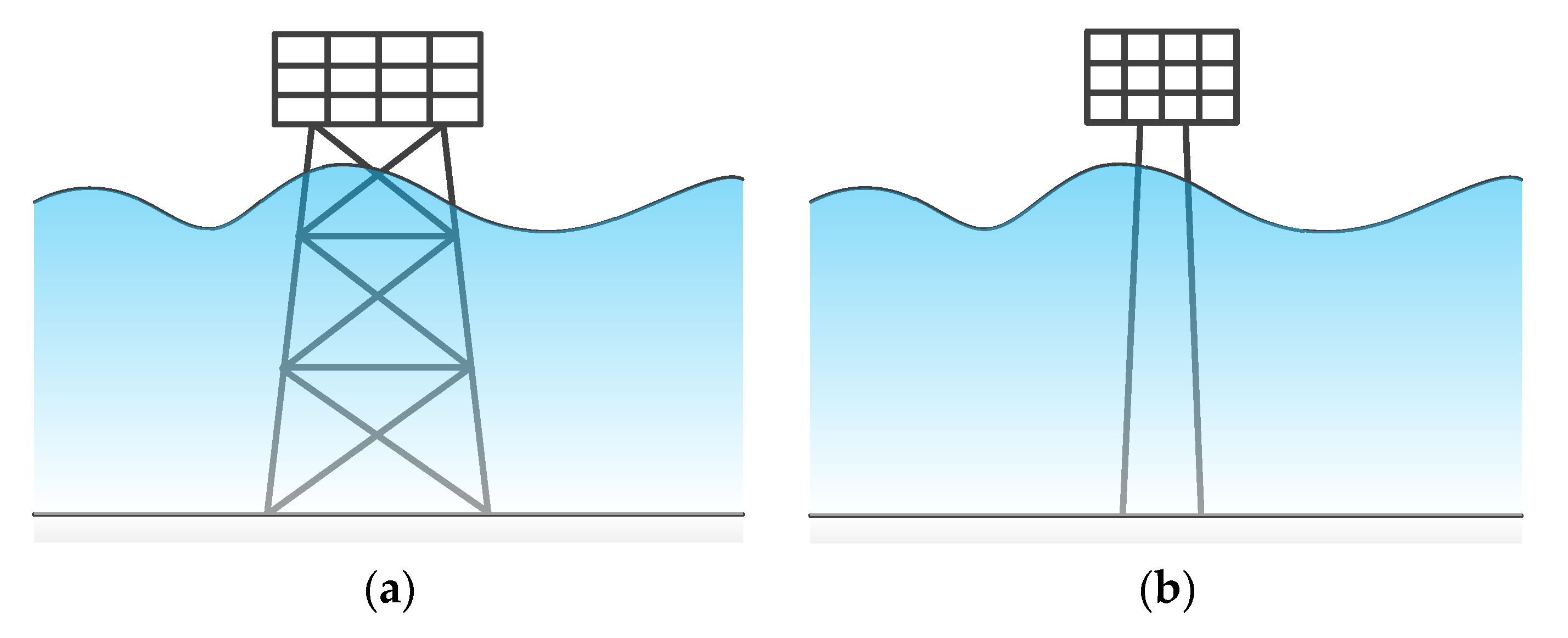
Offshore substations are important sustainable power infrastructures in wind farms [1]. Many expensive and delicate instruments are used in offshore substations. As shown in Figure 1, offshore substations are constructed to be supported by a jacket type or a mono-pile type, with sustainable power instruments equipped to the frame structure above sea level so that they are protected from sea intrusion [2]. However, located in a complex environment, particularly excited by stochastic wind, wave, and current loadings, they are often subjected to strong vibrations [3,4]. These long-time harmful vibrations adversely impact the normal operation of instruments, which may tremendously increase the operation and maintenance costs of sustainable power [5]. Additionally, vibrations may also induce damage to the bearing structures, which would cause disastrous accidents and serious economic losses [6]. Therefore, vibration control is highly desired to protect the facilities of offshore substations [7,8,9]. As offshore substations are constructed in the marine environment and bear many instruments, the space for vibration control devices is particularly limited; therefore, lightweight vibration control devices are highly desirable in offshore substations [10]. Therefore, vibration control devices with a light weight and high performance would benefit the development and maintenance of wind farms, which contribute to sustainable development.
Conventional vibration control devices are referred to as Tuned Mass Dampers (TMDs) [11]. TMDs are acknowledged for their simple configuration, feasible installation, effective vibration suppression performance, and low cost. Conventional TMDs have gained much research attention during parametric optimal design and control performance evaluations [12,13,14,15,16]. They have also been practically applied on various structures, such as buildings [17,18,19], bridges [20,21], wind turbines [22,23,24], etc., to resist different vibrations caused by seismic activity [19,21], wind [17,20], or waves [22,23,24], etc. However, the control performance of optimal designed TMDs is dependent on mass. In particular, with higher mass values (more weight), a better control performance can be achieved. This aspect may lead to an additional burden on the primary structure. Especially for offshore substations, a lightweight performance is highly desired. Therefore, the lightweight design of vibration control devices is an important practical issue to be addressed.
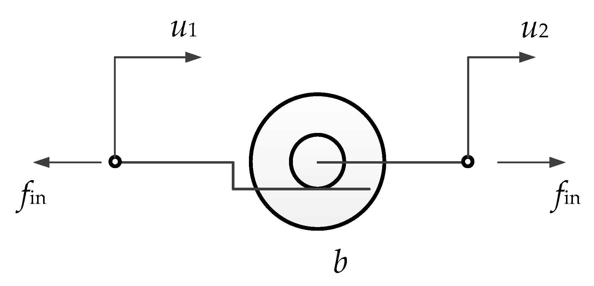
Recently, with the development of advanced mechanical design, a high-performance mechanical element named “inerter” was proposed and developed [25]. It originates from an interdisciplinary analogy between electronics and mechanics. An inerter element is characterized as outputting forces fin in proportion to the relative translation accelerations between its two terminals ( and ) [26], as shown in Equation (1).
Here, ü1 and ü2 denote the displacement of the terminals. The overhead dots denote a derivation with respect to time. The inertance coefficient is b, which has the same dimension as mass. This property can be physically achieved with a mechanism (such as rack-pinion [27], ball screw [28], living hinge [29], hydraulic mechanics [30], etc.) converting the translation deflection into rotation. With a flywheel, the rotation can produce a significant inertial effect. The schematic diagram of a general simplified symbol of an inerter element is shown in Figure 2. The circular plates indicate the flywheel used to generate the inertial-like force, as presented by Equation (1). The inertial effect is quantified by the inertance coefficient, which can be valued at hundreds of times the physical mass of the inerter device. With this feature, the lightweight design of a vibration control device may be realized.
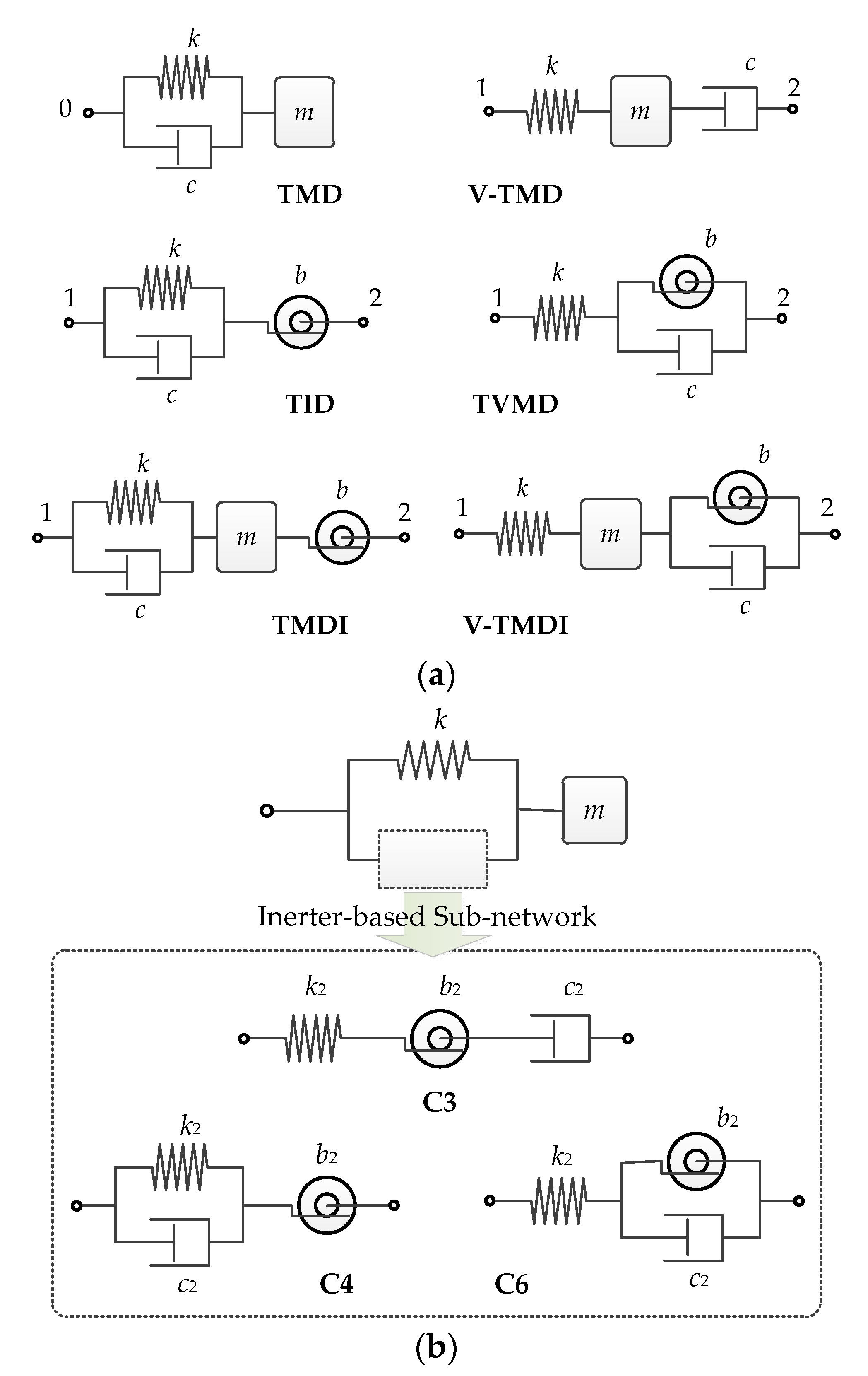
By adopting the inerter into conventional vibration control devices, many high-performance vibration absorbers have been developed and investigated. Among these, the Tuned Viscous Mass Damper was developed by Ikago’s laboratory using a ball screw mechanism [31]. With an excellent control performance, it became the first known inerter-based vibration absorber in a practical building [32], and it has gained much research attention recently [33,34,35]. A Tuned Mass Damper Inerter (TMDI) [36] and Tuned Inerter Damper (TID) [37] have also been developed for vibration control, subsequently as single-tuned vibration control devices. Their practical applicability has been further investigated and addressed in recent years [38,39,40,41,42]. A variant design of a TMD is addressed in [43], referred to as the V-TMD. It is found that TVMD and TID also follow such variant pairs. In this way, a V-TMDI is also developed [44]. The family of inerter-based single-tuned vibration control devices is shown as Figure 3a. A systematic investigation into inerter-based single-tuned vibration control devices was performed in [45,46]. Alternatively, by replacing the dashpot of the TMD with TVMD, a double-tuned vibration control device is developed, known as the Rotational Inertial Double-Tuned Mass Damper (RIDTMD) [47], which is also referred to as a tuned mass inerter system combining the advantages of both the TMD and TVMD [48]. In addition, other inerter-based sub-networks have been adopted to form double-tuned vibration control devices, which are investigated in [49,50,51,52]. According to the literature [49,53], the inerter-based sub-networks marked C3, C5, and C6, as shown in Figure 3b, exhibit stable and effective performances. The C6 configuration is merely the RIDTMD.
With the spring, dashpot, mass, and inerter elements, the lightweight design of vibration control devices for offshore substations was addressed in this paper. The optimal design and performance evaluation for different configurations, including various single- and double-tuned types, are compared and discussed in this paper. The rest of this paper is organized as follows. Firstly, the governing equations of the primary offshore substation structure to be controlled and coupling with different vibration control devices are displayed in Section 2. Subsequently, the optimal parameters of different vibration control devices are determined in Section 3. With a practical case of an offshore substation subjected to wave loads, the control performances of different vibration control devices are compared in Section 4. Finally, the conclusions are summarized in Section 5.
2. Vibration Control Mechanisms
In this section, the vibration control mechanisms for the primary offshore substation structure coupling vibration control devices are derived. Firstly, the primary offshore substation structure is simplified and modeled in Section 2.1. Subsequently, the primary structure coupling the conventional TMD and inerter-based single- and double-tuned vibration control devices is modeled in Section 2.2, Section 2.3 and Section 2.4, respectively. Both the differential governing equations in the time domain and the algebraic equation in the Laplace domain are provided in this section. Here, a genetic representation form of the vibration mechanism based on the Laplace equations is revealed.
2.1. Primary Offshore Substation Structure without Control
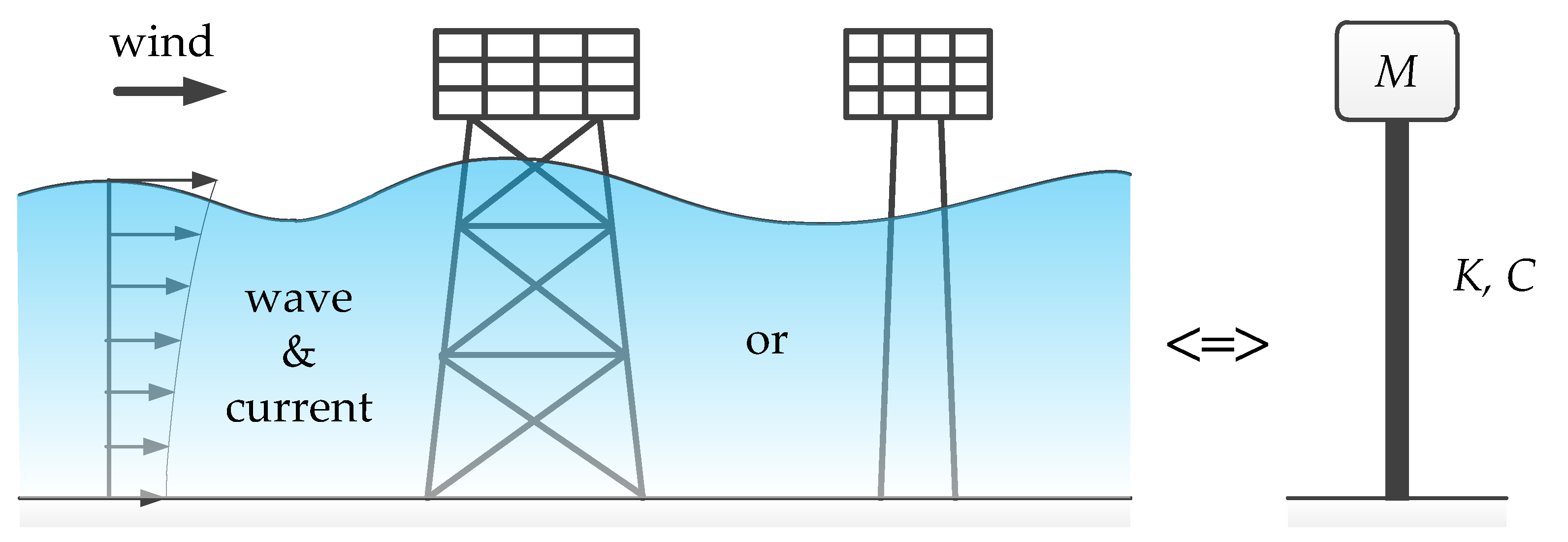
The primary offshore substation structure shown in Figure 1 is composed of a supporting truss or pile which arose from the sea floor, as well as the main frame of a substation building. The supporting truss or pile can be simplified as a cantilevered column characterized by stiffness K and damping C, whereas the main frame of the substation building is usually a low-rise steel frame, which is much stiffer than the supporting structure. It can be simplified as the main mass of M in this dynamic system. Thus, the primary offshore substation structure is simplified as a single-degree-of-freedom (SDOF) system, as shown on the sight side of Figure 4. The input excitation on the SDOF system is noted as f(t). Here, f(t) is the time history of the excitation force. It can be the resultant wave force acting on the underwater part of the supporting structure. As a system output, the vibration displacement response of the substation is denoted as x(t). The relationship between the input f(t) and output x(t) can be established based on the structural dynamic vibration analysis theory with a second-order differential equation.
In order to solve the structural dynamic differential equation in an algebraic manner, with Laplace transform, the relationship between the input f(t) and output x(t) is converted to a simple algebraic form of F(s) = X(s)(Ms2 + Cs + K). Here, s is the Laplace complex frequency, X(s) and F(s) are the Laplace transforms of x(t) and f(t). Although the SDOF structure without control is a simple case, this approach is effective in analyzing complex cases with complex vibration control devices, as shown in the follow sections.
2.2. Vibration Control with Conventional TMD
The conventional TMD, as demonstrated in Figure 3a, was attached on the primary mass of the primary offshore substation structure. The mass, damping, and stiffness coefficients of the TMD are denoted as m, c, and k, respectively. The governing equations of the primary structure coupling the TMD, as referred to [11,12,13], are written as
Here, ÿ denotes the displacement of the TMD mass relative to the ground. f0 denotes the output force of the TMD. The overhead dot means a derivation with respect to time. The output force of the TMD is produced by the Kelvin–Voigt element composed of a spring and dashpot in parallel connection [11], as provided by
Note that the expression of Equation (2) for the conventional TMD can be extended to more complex devices by changing the output force to adapt different characteristic vibration control devices.
By substituting Equation (3) into Equation (2), and performing Laplace transformation on both sides of the equations, the governing equations in the Laplace domain are obtained as
Here, Y(s) is the Laplace transform of y(t). Equation (4) can be regarded as a generic formulation for vibration control devices, with A1,2,3(s) being the characteristic functions, which are polynomial functions for single-tuned vibration control devices and are rational functions for double-tuned vibration control devices. For the most conventional TMD, they are obtained as Equation (5). Certainly, they are replaced with other forms for other complex vibration control devices.
2.3. Single-Tuned Vibration Control Devices
Single-tuned vibration control devices are categorized into two types, as displayed in Figure 2, namely the conventional type and the variant type. The governing equations for the abovementioned two types are displayed in this subsection.
As single-tuned vibration control devices are two-terminal-connected, as shown in Figure 5, the general governing equations can be formulated as
Here, ÿ denotes the displacement of the mass (in TMD [11,12,13], V-TMD [43], TMDI [36,40,42], or V-TMDI [44,45,46]) or massless node (TID [37,39,41], TVMD [31,32,33,34,35]) relative to the ground. φ is a location modification factor used to address location dependence. f1 and f2 denote the output force of the two terminals, as displayed in the following. Note that Equation (6) is an extended form of Equation (2), with the two force items f1 and f2 for the two terminals, respectively.
2.3.1. Conventional Type (TMDI)
The conventional type includes the TMD [11,12,13], TID [37,39,41], and TMDI [36,40,42]. Due to generality, the TMDI with mass, damping, stiffness, and inertance coefficients of m, c, k, and b is represented for this type. When the mass is absent (m = 0), it degenerates to the model of the TID. When the inertance is absent (b = 0), it becomes the model of the TMD [11,12,13].
This type is characterized by a Kelvin–Voigt element in one terminal, encoded as terminal 1, connected to the primary mass. Excluding the TMD [11,12,13] as a one-terminal-connected device, the TID [37,39,41] and TMDI [36,40,42] have an inerter element connected to the other end, encoded as terminal 2. It can be connected to the ground, or to a certain location of the primary structure if a ground connection is not feasible. Thus, f1 and f2 are written as
2.3.2. Variant Type (V-TMDI)
The other type is the variant type, including the V-TMD [43], TVMD [31,32,33,34,35], and V-TMDI [44,45,46]. For the sake of generality, the V-TMDI [44,45,46] with mass, damping, stiffness, and inertance coefficients of m, c, k, and b is represented. With an absent of mass (m = 0) or inerter (b = 0), the model of the TVMD [31,32,33,34,35] or V-TMD [43] can be obtained.
For this type, terminal 1 connects a spring, whereas a dashpot–inerter system in parallel connection is attached in terminal 2. Exclusively, the V-TMD [43] only has a dashpot in terminal 2. Thus, f1 and f2 are written as
By substituting Equation (9) into Equation (6) and performing Laplace transformation on both sides of the equations, the governing equations of the V-TMDI [44,45,46] in the Laplace domain are obtained in the format of Equation (4), with characteristic polynomials provided by
In Equations (6)–(10), the location modification factor φ is based on a Ritz–Galerkin truncation according to the fundamental mode. It is taken as the modal value where terminal 2 is connected. For a grounded connection, φ = 0.
2.4. Double-Tuned Vibration Control Devices
Double-tuned vibration control devices are replacing the dashpot of TMDs [11,12,13] with inerter-based sub-networks. The installations of double-tuned vibration control devices are similar to those of the TMD [11,12,13]. Only one terminal is connected to the primary mass, which exhibits a better installation feasibility. Thus, the governing equations of one-terminal-based double-tuned vibration control devices [49,50,51,52,53] are within the generic format of Equation (2), with a more complex output force of Equation (11) in place of a simple one in Equation (3):
Here, fC3,4, or 6 is the output force generated by the inerter-based sub-network. For configurations C3, C4, and C6 [49,50], with inerter, damping, and stiffness coefficients of b2, c2, and k2, it is governed as follows.
2.4.1. C6 Type (RIDTMD)
The C6 type double-tuned vibration control device is the most known RIDTMD [47]. Based on the equilibrium criterion, the output force fC6 in the time domain is derived as
Here, y1 is the displacement of the node in the C6 sub-network [49]. This dummy displacement variable can be eliminated algebraically with Laplace transforms, obtained as
Here, FC6(s) is the Laplace transform of fC6(t).
2.4.2. C4 Type
With Laplace transforms, the dummy displacement variable y1 is eliminated algebraically, as written by
2.4.3. C3 Type
In the C3 type sub-network [49,50], two dummy displacements on the connection joints of different elements are induced, y1 and y2. The fC3 in the time domain is governed by
With Laplace transforms, the dummy displacement variables y1 and y2 are eliminated, as written by
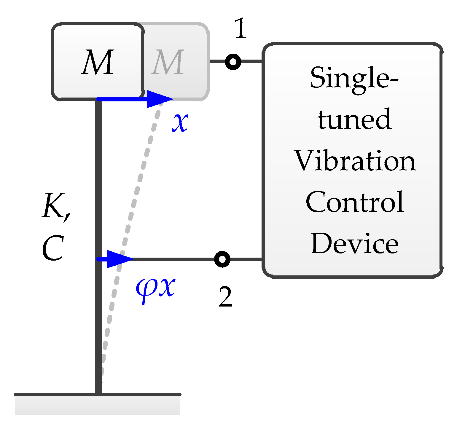
2.4.4. Mechanical Impedance Function
The above one-terminal vibration control devices connected on the primary mass, as displayed by Figure 6, can be generically formatted. The governing equations can be written in the general format of Equation (4), with characteristic functions provided by
Here, Ψ(s) is defined as a mechanical impedance function, denoted as
3. Determination of Optimal Parameters of Vibration Control Devices
In order to determine the optimal parameters to maximize the performances of vibration control devices, parametric optimization is performed in this section. Firstly, the methodology for parametric optimization is addressed in Section 3.1. Subsequently, the optimal parameters of single- and double-tuned vibration control devices are obtained and discussed in Section 3.2 and Section 3.3, respectively.
3.1. Parametric Optimization Method
3.1.1. Dynamic Amplification Function
The transfer function is defined as the quotient between the output response X(s) and the input excitation F(s). In the frequency domain, the frequency response function H(iω) is used to solve the variance of the dynamic response via the stochastic vibration theory. Here, the frequency response function H(iω) is taking s = iω for the transfer function, where i2 = −1. Sf(ω) is a spectral density function of the excitation f(t), where ω denotes the frequency.
In order to perform the analysis in a generic manner, the transfer functions are expressed in a dimensionless format. Like the analysis for many vibration control devices [43,44,45,46,49,50,51,52,53], the dynamic characteristic parameters for vibration control devices are demonstrated in Table 1.
In this way, with a generic governing equation as per Equation (4), the transfer function in a dimensionless form is obtained as
Here, is a dimensionless form of the characteristic functions. For single-tuned vibration control devices, based on Equations (8) and (10), Equations (21) and (22) are for the TMDI and V-TMDI, respectively.
For double-tuned vibration control devices, Equation (18) is reformatted as
Here, is the dimensionless mechanical impedance function, as provided by
The dynamic amplification function D(Ω) is defined as the modulus of the dimensionless transfer function. Here, the dimensionless excitation frequency is defined as . The dynamic amplification function denotes the dynamic factor of the response based on the static one at an excitation frequency of .
3.1.2. H-Norm-Based Optimization
The parameters of vibration control devices should be determined for optimization targets. The parameters of vibration control devices are divided into predetermined parameters denoted by a vector of π, and underdetermined parameters are represented by a vector of θ. The predetermined parameters are ones determined before parametric optimization as known parameters to be substituted into the optimization, like the mass ratio μ and the installation parameter φ. They are usually determined based on some presumptions and installation restrictions, whereas the underdetermined parameters are ones to be determined based on predetermined parameters to achieve better control performances, like the parameters (ν, ζd) for single-tuned cases, and (ν, γ, ζd) for double-tuned cases. The parametric optimization is to determine θopt(π) with an optimal target. Targeted on the norms of dynamic amplification functions, H-norm-based optimization criteria are presented.
H∞ optimization [11] is targeted by minimizing the infinity norm (maximum value) Dmax of the dynamic amplification function, as per
Here, θopt-∞(π) represents the optimal underdetermined parameters determined by H∞ optimization. θmin,max denote the lower and upper boundary of the parameter vector θ. H∞ optimization can be analytically approximated by the fixed-point approach, as presented in [1]. H∞ optimization is targeted by minimizing the maximum possible dynamic amplification factor over the whole frequency domain. This is particularly effective for harmonically or stochastically excited structures with various frequencies.
Alternatively, H2 optimization [13] is targeted on minimizing the second norm I of the dynamic amplification function, as per
Here, θopt-2(π) represents the optimal parameters determined by H2 optimization. The H2-norm I can be analytically obtained by the filter approach or Cauchy’s residue theorem. However, the H2 optimization results can be non-analytical for complicated cases. As the H2-norm corresponds to the standard deviation value of a dynamic response subjected to a white noise with a unit intensity (Sf(ω) = 1), it is particularly effective for broad-banded stochastically excitations.
3.2. Single-Tuned Vibration Control Devices
For single-tuned vibration control devices, the predetermined parameter vector is π = {μ, β, φ}, and the underdetermined parameter vector is θ = {ν, ζd}.
3.2.1. Conventional TMD
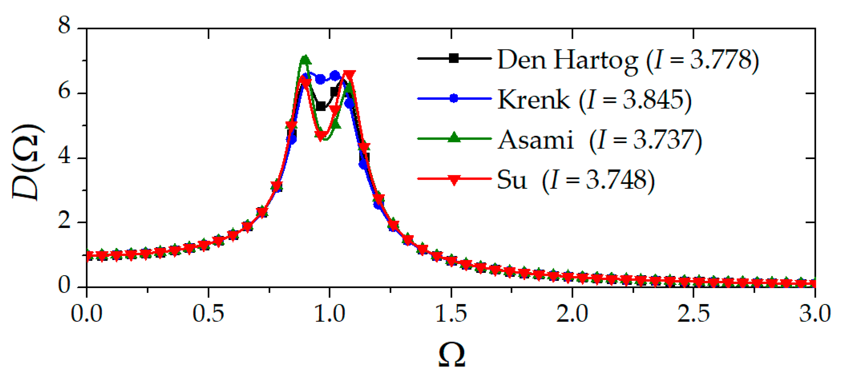
The solution of optimal parameters for the conventional TMD has been addressed extensively. Many analytical H-norm-based solutions are proposed [1,2,3,36]. The dynamic amplification functions under different optimal parameters for a conventional TMD with μ = 0.05 are calculated and illustratively demonstrated in Figure 7. The H2-norm for each solution is shown in the legend. Among these, the hybrid H∞–H2 solution [36] combines the advantages of the fixed-point approach for the H∞-norm and filter-based approach for the H2-norm. Thus, this method is adopted in the present investigation.
Moreover, in order to estimate the control performance, the H2-norm for the TMD with hybrid H∞–H2 solutions is obtained as
This result can be used as a standard to estimate the lightweight performances of double-tuned vibration control devices in Section 3.3.
3.2.2. Ground Connected Single-Tuned Vibration Control Devices
For ground connected single-tuned vibration control devices (φ = 0), based on the hybrid H∞–H2 optimization approach, the analytical optimal parameters are solved as Equation (28) for the conventional type and Equation (29) for the variant type.
It should be addressed that the H2 solutions for the variant type single-tuned vibration control devices cannot exist when the inertance coefficient is sufficiently large. Thus, the H∞–H2 optimization approach could provide a stable solution to adapt this situation.
3.2.3. Equivalent Mass Ratio Approach to Address the Installation Location
Considering the installation location with an arbitrary parameter φ, the exact analytical solutions can be derived as Equations (30) and (31) based on the H∞–H2 optimization criterion [46].
Here, the coefficients Γ1,2,3,4 are determined as Equation (32) for the conventional type and Equation (33) for the variant type.
By ignoring high-order tiny items, the solutions for these general cases can be simplified as Equations (34) and (35) for the conventional and variant types, respectively.
Here, an important parameter, the equivalent mass ratio μeq, is introduced, as defined by . The equivalent mass ratio can be used to estimate the lightweight performance of vibration control devices. The simplification Equations (34) and (35) are exactly the same as the exact solution Equations (30)–(33) when the product μβφ = 0. To be specific, when φ = 0, Equations (34) and (35) degenerate to Equations (28) and (29), respectively. When β = 0, Equation (34) degenerates to the solution of the TMD. The comparison between the exact and simplified solutions for different types and installation locations is shown in Figure 8. The simplified results are observed to be in good agreement with the exact solutions.
Particularly, the scope of application for the equivalent mass ratio approach should be addressed as . Beyond this scope, the adoption of an inerter does not effectively enhance the vibration control performance [35]. This criterion provides a limit for the installation of the inerter element. The concept of the equivalent mass ratio indicates the contribution of inertance with an installation on the vibration control as a mass in the TMD (or V-TMD). Also, with this approach, the weight reduction for inerter-based single-tuned vibration control devices can be estimated from a theoretical perspective.
3.3. Double-Tuned Vibration Control Devices
The parametric optimization problem of double-tuned vibration control devices is defined by the predetermined parameter vector as π = μ and the underdetermined parameter vector as θ = {β, ν, γ, ζd}. Different from single-tuned vibration control devices, the inerter in double-tuned vibration control devices is viewed as a sub-element of the inerter-based sub-network. Therefore, the inertance parameter β here is an underdetermined parameter rather than a predetermined parameter.
3.3.1. Optimal Parameters
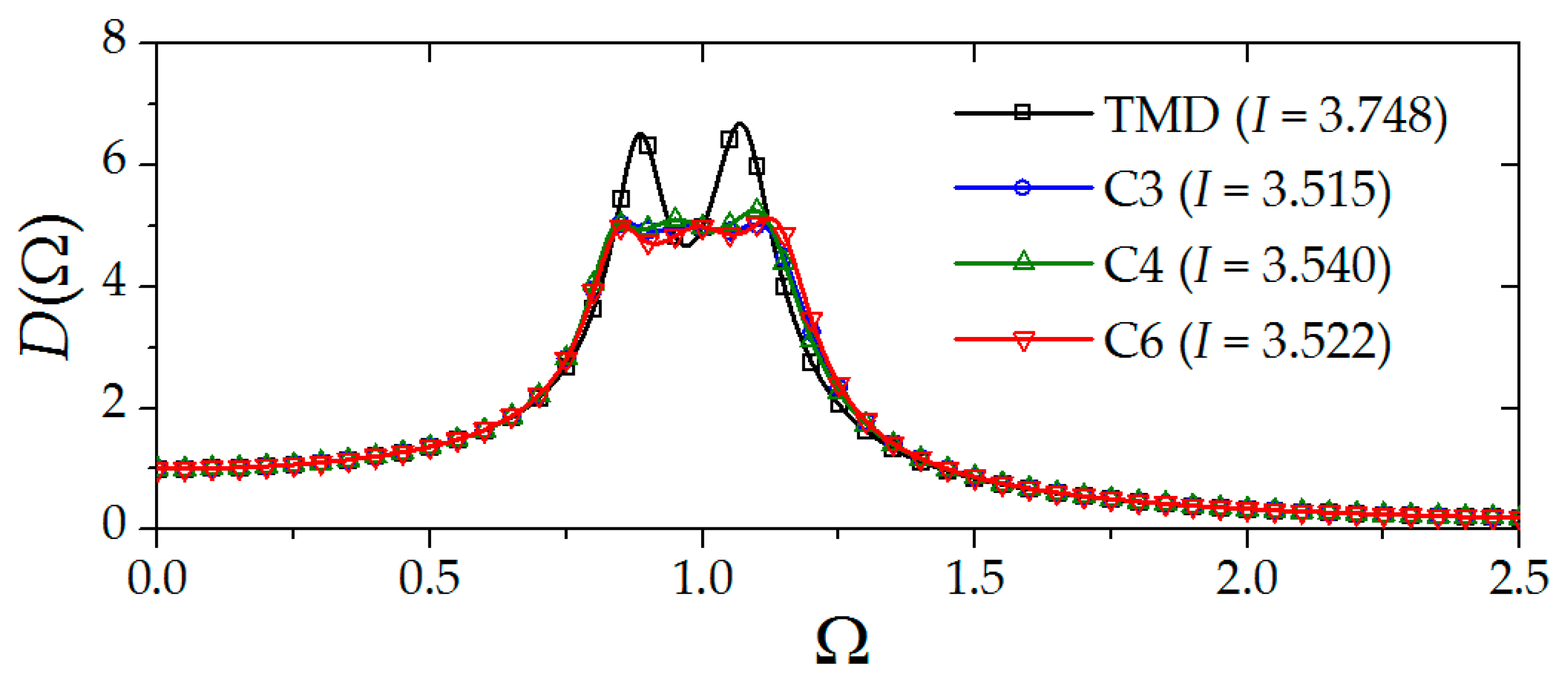
As the transfer function of double-tuned vibration control devices is more complicated than the previously addressed single-tuned vibration control devices, the analytical optimal parameters are more cumbersome, as derived from [49,50]. For the convenience of a practical application, the optimal parameters for double-tuned vibration control devices are empirically formulated in [53] with simple formulations. With these empirical formulations, the dynamic amplification functions for a conventional TMD and double-tuned vibration control devices with μ = 0.05 are calculated, as shown in Figure 9. It is noticed that the control performances (H-norms) of optimal designed double-tuned vibration control devices with C3, C4, and C6 sub-networks are similar, which are lower than a TMD with the same mass.
3.3.2. Equivalent Mass Ratio
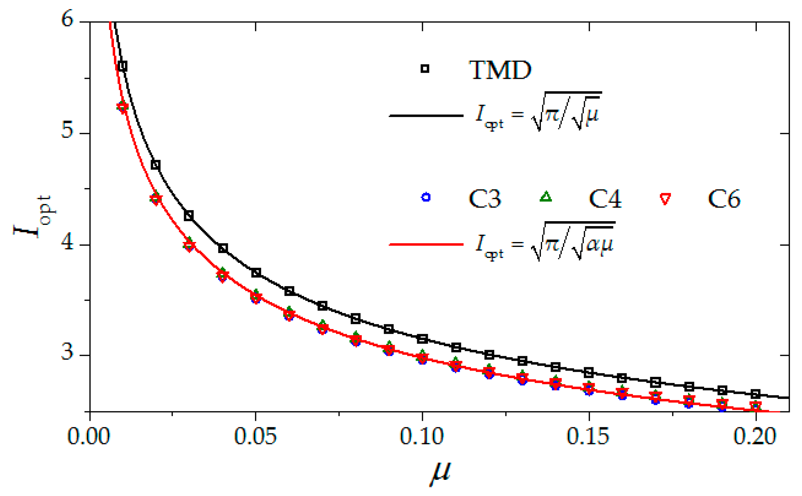
- In order to further quantify the lightweight vibration control performance, with the formant of the conventional TMD in Equation (27), an equivalent mass ratio for double-tuned vibration control devices is defined as μeq = αμ, with α being a mass magnification effect factor. The factor α is determined by equalizing the optimal H2-norms of double-tuned vibration control devices with those of the conventional TMD, as per Equation (36), via a least square technique.
- The optimal H2-norms of double-tuned vibration control devices and the conventional TMD are plotted in Figure 10. It is noticed that Equation (36) can fit well with the data, indicating the effectiveness of the equivalent mass approach. The resulting factor α is determined as 1.25, which indicates that the optimally designed double-tuned vibration control device may save 25% of the mass compared to a conventional TMD.
4. Vibration Control on a Practical Offshore Substation
In this section, the vibration control on a practical offshore station is subjected to wind, wave, and current loads. The basic calculation conditions are demonstrated in Section 4.1. The control performances of different vibration control devices are shown in Section 4.2. Finally, comparisons and discussions are displayed in Section 4.3.
4.1. Vibration Response Analysis
4.1.1. Finite Element Model of the Offshore Substation
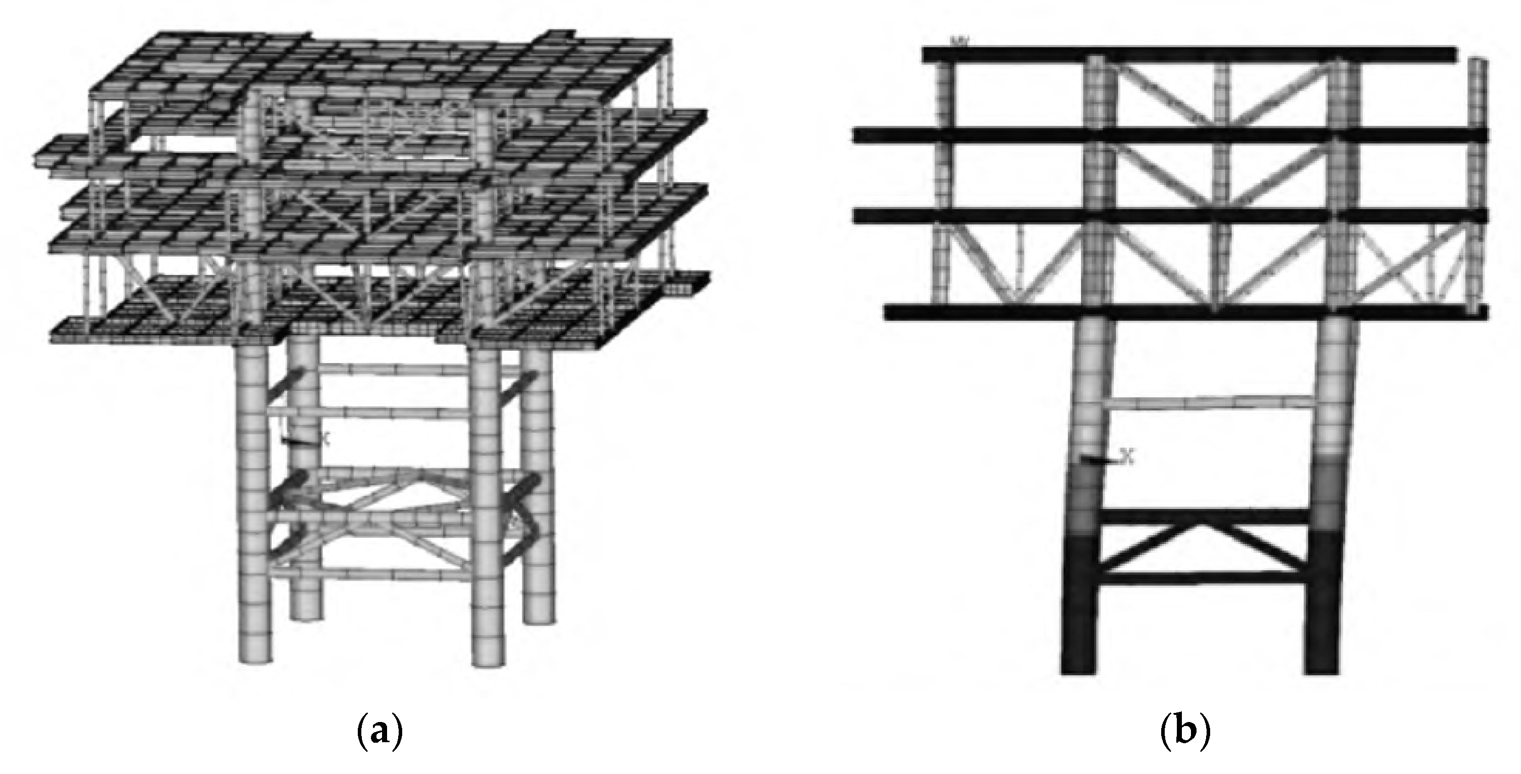
A practical 220 kV offshore substation from a wind farm is taken as an example for this case study. It is composed of a four-story steel structure supported on a jacket structure, as shown in Figure 11. The finite element model is established with ANSYS software; PIPE 16 elements are used to simulate the truss members. BEAM188 elements are used to simulate the frames of the upper structure. Like many engineering validation cases [42,53], the steel material is characterized as a density of 7850 kg/m3, a passion ratio of 0.3, and a Young’s modulus of 206 GPa.
Based on the modal analysis, the fundamental modal frequency of the offshore substation structure is calculated as 0.79 Hz. As shown in Figure 11b, the mode is characterized as a horizontal vibration. The inherent damping of the structure is taken as Rayleigh damping with a damping ratio of 0.04.
4.1.2. Environmental Excitations
In order to provide calculation inputs for readers to follow, the determination of environmental excitations is provided in this section.
- (1)
- Wind load
The wind velocity Vz and the turbulence intensity Iz are assumed to follow a power law along the height z, with a power index of 0.12 for a marine terrain [4], as shown in Equation (37).
Here, V10 is a basic wind speed at a standard reference height of 10 m. The stochastic wind velocity spectrum Swind(ω) is taken as the Davenport spectrum as
Here, n = 600ω/(πV10) is the reduced frequency. With a spectral representation method [54], the stochastic wind speed Vz(t) can be obtained. Then, the wind load on each structural node fwind(t) can be obtained as
where Cp is the wind pressure coefficient, ρair is the air density, and A is the tributary area of the node.
- (2)
- Wave and current loads
The wave is assumed based on a linear airy wave. The horizontal velocity and acceleration of the water particles vx(z, t) and ax(z, t) are expressed by
Here, Φ is the velocity potential function. ωi, κi, and εi (i = 1, 2, …, N) are the frequency, wave number, and stochastic phase of the ith wave. d is the water depth. Swave(ω) is the wave height spectrum, which is taken as the JONSWAP spectrum as per Equation (41) [55]. Δω is the frequency interval.
Here, A is a normalized factor, taken as 0.076; TP is the characteristic period of the wave; υ is a spectral peak factor, taken as 3.3; and σ is the spectral shape factor, taken as 0.07 for ω ≤ 2π/TP and 0.09 for ω > 2π/TP. With Morison’s formula, the wave and current loads on an underwater pipe element fw&c(t) are calculated by
where CD is a drag coefficient, taken as 1.2; CM is an inertial coefficient, taken as 2.0; vc is the mean current velocity; ρsea is the density of sea water; D and h are the diameter and tributary height of the pipe element, respectively; and A is the tributary area of the element.
4.2. Vibration Control Performance
4.2.1. Vibration Control Devices
Vibration control devices are selected as conventional TMDs with a mass ratio of μ = 0.05, which is assumed to be the maximum acceptable proportion for engineering structures. For single-tuned vibration control devices, the TMDI and TVMD are selected as illustrations. Considering that the installation is between the top of the lowest jacket and the floor of the upper platform, φ is calculated as 0.5 based on the modal analysis, as shown in Figure 11b. The TMDI is illustrated with μ = 0.01, β = 0.16, and φ = 0.5. The TVMD is illustrated with β = 0.20 and φ = 0.5. The illustrated single-tuned vibration control devices are characterized with μeq = 0.05. For the double-tuned vibration control device, a RIDTMD with μeq = 0.05 is selected, which is characterized as μ = 0.04. The underdetermined parameters are calculated with simplified formulas, as presented in Section 3. The details of the calculation cases are shown in Table 2.
4.2.2. Vibration Responses and Control Rates
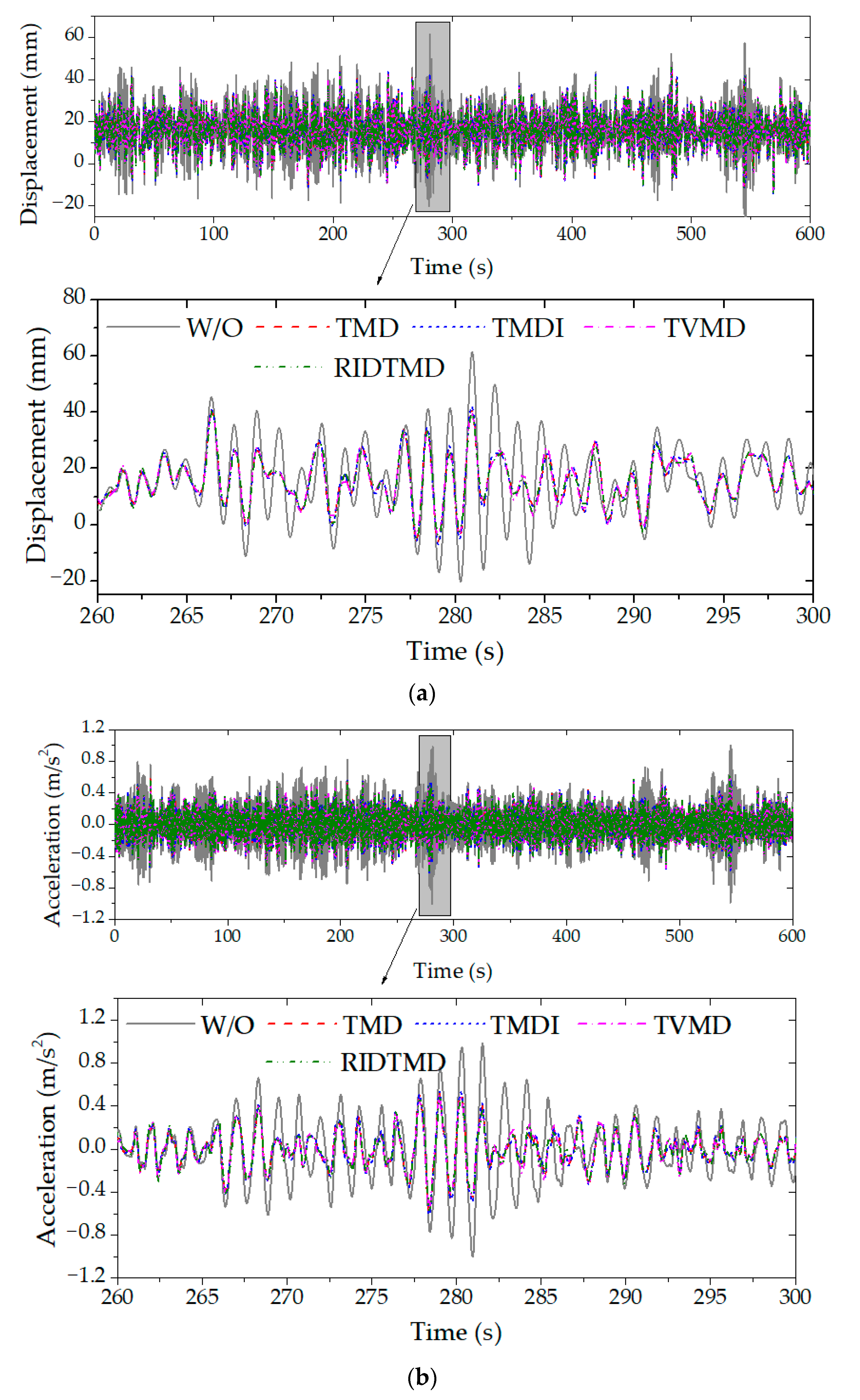
The dynamic responses of the offshore substation are analyzed with a transient time history analysis method. The top displacement and acceleration responses of the offshore substation for different cases are shown in Figure 12.
It can be observed from Figure 12 that with vibration control devices, the vibration responses, including both displacement and acceleration, are significantly suppressed. This shows the effectiveness of the vibration control device. Moreover, with the same equivalent ratio, despite the difference in the configurations of vibration control devices, the reduction effect may be similar. This further validates the effectiveness of lightweight performance estimated with the equivalent mass ratio, as presented in Section 3.2.3 and Section 3.3.2. This aspect will be further addressed in Section 4.3.
In order to further quantify the control performances, the reduction rate of the dynamic and maximum responses Jdyn and Jtot is defined, as expressed by
Here, qUC(t) and qC(t) are the uncontrolled and controlled responses, respectively. SD[·] denotes the standard deviation value of the dynamic responses. Max[·] denotes the maximum of the absolute value of the total responses.
The statistics of the obtained responses and the corresponding control rates are summarized and listed in Table 3. It is obtained that the maximum displacement is reduced by over 24%, and the maximum acceleration is reduced by up to 37%, which are beneficial to both prohibit the supporting structure from unfavorable dynamic loadings and protect the devices from harmful vibrations.
4.3. Comparisons of Different Vibration Control Devices
It can be observed from Table 3 that with a properly designed single- or double-tuned vibration control device, the control performance of the inerter-based vibration control device is similar to a conventional TMD with a same equivalent mass ratio. Moreover, it can be observed from Figure 12 that the time histories for vibration control devices with the same equivalent mass ratio are also similar. These results provide strong evidence for the effectiveness of the equivalent mass ratio, as presented in Section 3.
However, inerter-based devices exhibit a better lightweight performance. Specifically, the double-tuned inerter-based device could save 25% of the mass compared to the TMD. With the TMDI, the responsibility for the mass could be shared with dual-end connected inerters. The presented TMDI conserved only 20% of the mass of the TMD, whereas the TVMD completely replaced the mass block with an inerter, which has a superior lightweight vibration control performance. Thus, we strongly recommend that the TVMD is practically applied on offshore substations as a lightweight vibration control device.
5. Conclusions
Offshore substations are important sustainable power infrastructures subjected to strong vibrations induced by wind, waves, and currents. In order to protect the structure and facilities from vibration, vibration control devices are required.
In this paper, the lightweight design issue of vibration control devices for offshore substations is addressed with an inerter element. Inerter-based single-tuned vibration control devices are usually dual-end connected. The ground connection usually exhibits excellent lightweight vibration control performance. When ground connection is prohibited, it can be installed on the primary structure. However, the contribution of an inerter is discounted with the modal parameter. Double-tuned vibration control devices with a single terminal exhibit good installation feasibility. Although they use different inerter-based sub-networks, the optimal control performances are similar.
Through a practical example of a practical offshore substation, properly designed vibration control devices are proven to be effective in controlling the vibration induced by the marine environment of wind, waves, and currents. Inerter-based devices exhibit a better lightweight performance. Specifically, the double-tuned inerter-based device could save approximately 25% of the mass compared to the conventional TMD. With the TMDI, the responsibility for the mass could be shared with dual-end connected inerters, whereas the TVMD completely replaces the mass block with an inerter, which has a superior lightweight vibration control performance.
Inerter-based vibration control devices are characterized by a high performance and being lightweight. They have the potential to be applied for use in vibration control and energy harvesting in sustainable power industries. To adapt complex scenarios (such as multi-hazards, including seismic, wind, waves, ice, etc.), various primary structures (offshore platforms, wind turbines, low-carbon building structures, etc.), and multi-functions (such as balancing stability, recycling mechanical, ocean energy, etc.), further investigations are required.
Author Contributions
Conceptualization, Y.W.; methodology, Y.W.; validation, C.X. and M.Y.; formal analysis, C.X. and M.Y.; writing—original draft preparation, C.X.; writing—review and editing, M.Y.; supervision, Z.H.; project administration, C.X.; funding acquisition, Y.W. All authors have read and agreed to the published version of the manuscript.
Funding
This research was funded by the Science and Technology Project of China Southern Power Grid, grant number 0300002023030103GH00130.
Institutional Review Board Statement
Not applicable.
Informed Consent Statement
Not applicable.
Data Availability Statement
Data are contained within the article.
Conflicts of Interest
Y.W., C.X. and M.Y. were employed by the company Guangdong Power Grid Corporation. The remaining authors declare that the research was conducted in the absence of any commercial or financial relationships that could be construed as a potential conflict of interest.
References
- Faraggiana, E.; Ghigo, A.; Sirigu, M.; Petracca, E.; Giorgi, G.; Mattiazzo, G.; Bracco, G. Optimal floating offshore wind farms for Mediterranean islands. Renew. Energy 2024, 221, 119785. [Google Scholar] [CrossRef]
- Wang, H.J.; Liu, C.; Guo, Y.H.; Zhao, Y.; Li, X.Y.; Lian, J.J. Experimental and numerical research on the wet-towing of wide-shallow bucket jacket foundation for offshore substation. Ocean Eng. 2023, 275, 114126. [Google Scholar] [CrossRef]
- Elobeid, M.; Pillai, A.C.; Tao, L.; Ingram, D.; Hanssen, J.E.; Mayorga, P. Implications of wave–current interaction on the dynamic responses of a floating offshore wind turbine. Ocean Eng. 2024, 292, 116571. [Google Scholar] [CrossRef]
- Townsend, J.F.; Xu, G.J.; Jin, Y.J.; Yu, E.B.; Wei, H.; Han, Y. On the development of a generalized atmospheric boundary layer velocity profile for offshore engineering applications considering wind–wave interaction. Ocean Eng. 2023, 286, 115621. [Google Scholar] [CrossRef]
- Kikuchi, Y.; Ishihara, T. Assessment of capital expenditure for fixed-bottom offshore wind farms using probabilistic engineering cost model. Appl. Energy 2023, 341, 120912. [Google Scholar] [CrossRef]
- Sykes, V.; Collu, M.; Coraddu, A. A Review and Analysis of the Uncertainty Within Cost Models for Floating Offshore Wind Farms. Renew. Sustain. Energy Rev. 2023, 186, 113634. [Google Scholar] [CrossRef]
- Danovaro, R.; Bianchelli, S.; Brambilla, P.; Brussa, G.; Corinaldesi, C.; Del Borghi, A.; Dell’Anno, A.; Fraschetti, S.; Greco, S.; Grosso, M.; et al. Making eco-sustainable floating offshore wind farms: Siting, mitigations, and compensations. Renew. Sustain. Energy Rev. 2024, 197, 114386. [Google Scholar] [CrossRef]
- Machado, M.R.; Dutkiewicz, M.; Colherinhas, G.B. Metamaterial-based vibration control for offshore wind turbines operating under multiple hazard excitation forces. Renew. Energy 2024, 223, 120056. [Google Scholar] [CrossRef]
- Rezaei, F.; Contestabile, P.; Vicinanza, D.; Azzellino, A. Towards understanding environmental and cumulative impacts of floating wind farms: Lessons learned from the fixed-bottom offshore wind farms. Ocean Coast. Manag. 2023, 243, 106772. [Google Scholar] [CrossRef]
- Díaz-Motta, A.; Díaz-González, F.; Villa-Arrieta, M. Energy sustainability assessment of offshore wind-powered ammonia. J. Clean. Prod. 2023, 420, 138419. [Google Scholar] [CrossRef]
- Ormondroyd, J.; Den Hartog, J.P. The theory of the dynamic vibration absorber. Trans. ASME 1928, 50, 9–22. [Google Scholar] [CrossRef]
- Krenk, S.; Høgsberg, J. Tuned mass absorbers on damped structures under random load. Probabilistic Eng. Mech. 2008, 23, 408–415. [Google Scholar] [CrossRef]
- Asami, T.; Nishihara, O.; Baz, A.M. Analytical solutions to H∞ and H2 optimization of dynamic vibration absorbers attached to damped linear systems. J. Vib. Acoust. 2002, 124, 284–295. [Google Scholar] [CrossRef]
- Bisegna, P.; Caruso, G. Closed-form formulas for the optimal pole-based design of tuned mass dampers. J. Sound Vib. 2012, 331, 2291–2314. [Google Scholar] [CrossRef]
- Krenk, S.; Høgsberg, J. Tuned mass absorber on a flexible structure. J. Sound Vib. 2014, 333, 1577–1595. [Google Scholar] [CrossRef]
- Argenziano, M.; Faiella, D.; Carotenuto, A.R.; Mele, E.; Fraldi, M. Generalization of the Den Hartog model and rule-of-thumb formulas for optimal tuned mass dampers. J. Sound Vib. 2022, 538, 117213. [Google Scholar] [CrossRef]
- Sun, X.; Wu, H.; Wu, Y.; Su, N. Wind-induced responses and control of a Kilometer skyscraper with mass and viscous dampers. J. Build. Eng. 2021, 43, 102552. [Google Scholar] [CrossRef]
- Kaveh, A.; Javadi, S.M.; Moghanni, R.M. Optimal structural control of tall buildings using tuned mass dampers via chaotic optimization algorithm. Structures 2020, 28, 2704–2713. [Google Scholar] [CrossRef]
- Domizio, M.; Garrido, H.; Ambrosini, D. Single and multiple TMD optimization to control seismic response of nonlinear structures. Eng. Struct. 2022, 252, 113667. [Google Scholar] [CrossRef]
- Lin, Y.Y.; Cheng, C.M.; Lee, C.H. A tuned mass damper for suppressing the coupled flexural and torsional buffeting response of long-span bridges. Eng. Struct. 2000, 22, 1195–1204. [Google Scholar] [CrossRef]
- Labbafi, S.F.; Shooshtari, A.; Mohtashami, E. Optimal design of friction tuned mass damper for seismic control of an integral bridge. Structures 2023, 58, 105200. [Google Scholar] [CrossRef]
- Wang, J.W.; Liang, X.; Wang, L.Z.; Wang, B.X.; Wang, L.L. The influence of tuned mass dampers on vibration control of monopile offshore wind turbines under wind-wave loadings. Ocean Eng. 2023, 278, 114394. [Google Scholar]
- Jahangiri, V.; Sun, C.; Kong, F. Study on a 3D pounding pendulum TMD for mitigating bi-directional vibration of offshore wind turbines. Eng. Struct. 2021, 241, 112383. [Google Scholar] [CrossRef]
- Elias, S. Vibration improvement of offshore wind turbines under multiple hazards. Structures 2024, 59, 105800. [Google Scholar] [CrossRef]
- Smith, M.C. Synthesis of mechanical networks: The inerter. IEEE Trans. Autom. Control 2002, 47, 1648–1662. [Google Scholar] [CrossRef]
- Ma, R.S.; Bi, K.M.; Hao, H. Inerter-based structural vibration control: A state-of-the-art review. Eng. Struct. 2021, 243, 112655. [Google Scholar] [CrossRef]
- Sun, L.; Hong, D.; Chen, L. Cables interconnected with tuned inerter damper for vibration mitigation. Eng. Struct. 2017, 151, 57–67. [Google Scholar] [CrossRef]
- Papageorgiou, C.; Houghton, N.E.; Smith, M.C. Experimental testing and analysis of inerter devices. J. Dyn. Syst. Meas. Control 2009, 131, 101–116. [Google Scholar] [CrossRef]
- John, E.D.A.; Wagg, D.J. Design and testing of a frictionless mechanical inerter device using living-hinges. J. Frankl. Inst. 2019, 356, 7650–7668. [Google Scholar] [CrossRef]
- De Domenico, D.; Deastra, P.; Ricciardi, G.; Sims, N.D.; Wagg, D.J. Novel fluid inerter based tuned mass dampers for optimised structural control of base-isolated buildings. J. Frankl. Inst. 2019, 356, 7626–7649. [Google Scholar] [CrossRef]
- Ikago, K.; Saito, K.; Inoue, N. Seismic control of single-degree-of-freedom structure using tuned viscous mass damper. Earthq. Eng. Struct. Dyn. 2012, 41, 453–474. [Google Scholar] [CrossRef]
- Ikago, K.; Sugimura, Y.; Saito, K.; Inoue, N. Modal response characteristics of a multiple-degree-of-freedom structure incorporated with tuned viscous mass dampers. J. Asian Arch. Build. Eng. 2012, 11, 375–382. [Google Scholar] [CrossRef]
- Zhang, R.F.; Zhao, Z.P.; Pan, C.; Ikago, K.; Xue, S.T. Damping enhancement principle of inerter system. Struct. Control Health Monit. 2020, 27, e2523. [Google Scholar] [CrossRef]
- Su, N.; Bian, J.; Peng, S.T.; Xia, Y. Impulsive resistant optimization design of tuned viscous mass damper (TVMD) based on stability maximization. Int. J. Mech. Sci. 2023, 239, 107876. [Google Scholar] [CrossRef]
- Mustapha, A.; Zhang, X.; Atroshchenko, E.; Jaroon, R. Vibration control of inerter-enhanced mega sub-controlled structure system (MSCSS) and the reliability analysis of the structure under seismic action. Eng. Struct. 2024, 241, 117508. [Google Scholar]
- Marian, L.; Giaralis, A. Optimal design of a novel tuned mass-damper-inerter (TMDI) passive vibration control configuration for stochastically support-excited structural systems. Probabilistic Eng. Mech. 2014, 38, 156–164. [Google Scholar] [CrossRef]
- Lazar, I.F.; Neild, S.A.; Wagg, D.J. Using an inerter-based device for structural vibration suppression. Earthq. Eng. Struct. Dyn. 2014, 43, 1129–1147. [Google Scholar] [CrossRef]
- Deastra, P.; Wagg, D.; Sims, N.; Akbar, M. Tuned inerter dampers with linear hysteretic damping. Earthq. Eng. Struct. Dyn. 2020, 49, 1216–1235. [Google Scholar] [CrossRef]
- Alotta, G.; Failla, G. Improved inerter-based vibration absorbers. Int. J. Mech. Sci. 2021, 192, 106087. [Google Scholar] [CrossRef]
- Su, N.; Peng, S.T.; Xia, Y. Filter-based inerter location dependence analysis approach of Tuned mass damper inerter (TMDI) and optimal design. Eng. Struct. 2022, 250, 113459. [Google Scholar] [CrossRef]
- Islam, N.U.; Jangid, R.S. Optimum parameters of tuned inerter damper for damped structures. J. Sound Vib. 2022, 537, 117218. [Google Scholar] [CrossRef]
- Fitzgerald, B.; McAuliffe, J.; Baisthakur, S.; Sarkar, S. Enhancing the reliability of floating offshore wind turbine towers subjected to misaligned wind-wave loading using tuned mass damper inerters (TMDIs). Renew. Energy 2023, 221, 522–538. [Google Scholar] [CrossRef]
- Ren, M.Z. A variant design of the dynamic vibration absorber. J. Sound Vib. 2001, 245, 762–770. [Google Scholar] [CrossRef]
- Masnata, C.; Matteo, A.D.; Adam, C.; Pirrotta, A. Smart structures through nontraditional design of Tuned Mass Damper Inerter for higher control of base isolated systems. Mech. Res. Commun. 2020, 105, 103513. [Google Scholar] [CrossRef]
- Su, N.; Bian, J.; Peng, S.T.; Xia, Y. Generic optimal design approach for inerter-based tuned mass systems. Int. J. Mech. Sci. 2022, 233, 107654. [Google Scholar] [CrossRef]
- Su, N.; Chen, Z.Q.; Xia, Y.; Bian, J. Hybrid analytical H-norm optimization approach for dynamic vibration absorbers. Int. J. Mech. Sci. 2024, 264, 108796. [Google Scholar] [CrossRef]
- Garrido, H.; Curadelli, O.; Ambrosini, D. Improvement of tuned mass damper by using rotational inertia through tuned viscous mass damper. Eng. Struct. 2013, 56, 2149–2153. [Google Scholar] [CrossRef]
- Zhang, L.; Xue, S.T.; Zhang, R.F.; Xie, L.Y.; Hao, L.F. Simplified multimode control of seismic response of high-rise chimneys using distributed tuned mass inerter systems (TMIS). Eng. Struct. 2021, 228, 111550. [Google Scholar] [CrossRef]
- Hu, Y.L.; Chen, M.Z.Q.; Shu, Z.; Huang, L.X. Analysis and optimisation for inerter-based isolators via fixed-point theory and algebraic solution. J. Sound Vib. 2015, 346, 17–36. [Google Scholar] [CrossRef]
- Barredo, E.; Blanco, A.; Colín, J.; Penagos, V.M.; Abúndez, A.; Luis, G.V.; Meza, V.; Cruz, R.H.; Mayen, J. Closed-form solutions for the optimal design of inerter-based dynamic vibration absorbers. Int. J. Mech. Sci. 2018, 144, 41–53. [Google Scholar] [CrossRef]
- Barredo, E.; Mendoza Larios, J.G.; Colín, J.; Mayen, J.; Flores-Hernandez, A.A.; Arias-Montiel, M. A novel high-performance passive non-traditional inerter-based dynamic vibration absorber. J. Sound Vib. 2020, 485, 115583. [Google Scholar] [CrossRef]
- Barredo, E.; Rojas, G.L.; May´en, J.; Flores-Hernandez, A.A. Innovative negative-stiffness inerter-based mechanical networks. Int. J. Mech. Sci. 2021, 205, 106597. [Google Scholar] [CrossRef]
- Su, N.; Peng, S.T.; Hong, N.N.; Xia, Y. Wind-induced vibration absorption using inerter-based double tuned mass dampers on slender structures. J. Build. Eng. 2022, 58, 104993. [Google Scholar] [CrossRef]
- Melaku, A.F.; Bitsuamlak, G.T. A divergence-free inflow turbulence generator using spectral representation method for large-eddy simulation of ABL flows. J. Wind. Eng. Ind. Aerodyn 2021, 212, 104580. [Google Scholar] [CrossRef]
- Mazzaretto, O.M.; Menéndez, M.; Lobeto, H. A global evaluation of the JONSWAP spectra suitability on coastal areas. Ocean Eng. 2022, 266, 112756. [Google Scholar] [CrossRef]
Figure 1.
Schematic diagrams of offshore substations. (a) Jacket-type offshore substation. (b) Mono-pile-type offshore substation.
Figure 1.
Schematic diagrams of offshore substations. (a) Jacket-type offshore substation. (b) Mono-pile-type offshore substation.

Figure 2.
A general simplified symbol of an inerter element.

Figure 3.
Various inerter-based single- and double- tuned vibration control devices. (a) Single-tuned vibration control devices. (b) Double-tuned vibration control devices.
Figure 3.
Various inerter-based single- and double- tuned vibration control devices. (a) Single-tuned vibration control devices. (b) Double-tuned vibration control devices.

Figure 4.
Simplification of the dynamic structural system for the offshore substation.

Figure 5.
A schematic diagram of a primary structure coupling a two-terminal-connected single-tuned vibration control device.
Figure 5.
A schematic diagram of a primary structure coupling a two-terminal-connected single-tuned vibration control device.

Figure 6.
A schematic diagram of a primary structure coupling a one-terminal-connected vibration control device (a TMD or a double-tuned vibration control device) generically expressed by a mechanical impedance function.
Figure 6.
A schematic diagram of a primary structure coupling a one-terminal-connected vibration control device (a TMD or a double-tuned vibration control device) generically expressed by a mechanical impedance function.

Figure 7.
Dynamic amplification functions under different optimal parameters for a conventional TMD with μ = 0.05.
Figure 7.
Dynamic amplification functions under different optimal parameters for a conventional TMD with μ = 0.05.

Figure 8.
The comparison of dynamic amplification functions between the exact and simplified solutions for different types and installation locations (μ = 0.01; β = 0.10; φ = 0.2, 0.4, and 0.6). (a) Conventional type of TMDI; (b) variant type of V-TMDI.
Figure 8.
The comparison of dynamic amplification functions between the exact and simplified solutions for different types and installation locations (μ = 0.01; β = 0.10; φ = 0.2, 0.4, and 0.6). (a) Conventional type of TMDI; (b) variant type of V-TMDI.

Figure 9.
Dynamic amplification functions under optimal parameters for a conventional TMD and double-tuned vibration control devices with μ = 0.05.
Figure 9.
Dynamic amplification functions under optimal parameters for a conventional TMD and double-tuned vibration control devices with μ = 0.05.

Figure 10.
The optimal H2-norms of double-tuned vibration control devices and the conventional TMD.

Figure 11.
Finite element model and the fundamental mode of the offshore substation structure. (a) Finite element model. (b) Fundamental modal shape.
Figure 11.
Finite element model and the fundamental mode of the offshore substation structure. (a) Finite element model. (b) Fundamental modal shape.

Figure 12.
The top displacement and acceleration responses of the offshore substation for different cases. (a) The top displacement responses for the uncontrolled and different controlled cases. (b) The acceleration response histories for the uncontrolled and different controlled cases.
Figure 12.
The top displacement and acceleration responses of the offshore substation for different cases. (a) The top displacement responses for the uncontrolled and different controlled cases. (b) The acceleration response histories for the uncontrolled and different controlled cases.


Table 1.
Dynamic characteristic parameters for vibration control devices.
| Symbol | Expression | Physical Meaning |
|---|---|---|
| The natural frequency of the primary offshore substation structure. | ||
| The damping ratio of the primary offshore substation structure. | ||
| The tuning mass ratio of the vibration control device. | ||
| The tuning inertance ratio of the vibration control device. Note that for a single-tuned vibration control device, b2 = 0, whereas for a double-tuned vibration control device, b = 0. | ||
| The nominal frequency of the vibration control device. Note that for a double-tuned vibration control device, b = 0. | ||
| The tuning frequency ratio of the vibration control device. | ||
| The secondary nominal frequency of the sub-network of the double-tuned vibration control device. | ||
| The secondary tuning frequency ratio of the double-tuned vibration control device. | ||
| The nominal damping ratio of the vibration control device. Note that for a double-tuned vibration control device, b = 0. | ||
| The dimensionless Laplace complex frequency. |
Table 2.
Details of vibration control devices for each case.
| Case # | Device | Predetermined Parameter | Underdetermined Parameter |
|---|---|---|---|
| 0 | None | — | — |
| 1 | TMD | μ = 0.05 | ν = 0.9524, ζd = 0.1118 |
| 2 | TMDI | μ = 0.01, β = 0.16, φ = 0.5 | ν = 0.9524, ζd = 0.1118 |
| 3 | TVMD | β = 0.20, φ = 0.5 | ν = 1.0260, ζd = 0.1147 |
| 4 | RIDTMD | μ = 0.04 | β = 0.0046, ν = 0.9259, γ = 1.1200, ζd = 0.0234 |
Table 3.
The statistics of the obtained responses and the corresponding control rates.
| Response | Case # | Device | SD[q(t)] | Jdyn (%) | Max[q(t)] | Jtot (%) |
|---|---|---|---|---|---|---|
| Displacement (mm) | 0 | None | 11.1 | — | 61.5 | — |
| 1 | TMD | 8.4 | 24.4 | 46.2 | 24.9 | |
| 2 | TMDI | 8.5 | 24.0 | 46.3 | 24.7 | |
| 3 | TVMD | 8.1 | 26.9 | 46.2 | 24.8 | |
| 4 | RIDTMD | 8.2 | 26.7 | 46.3 | 24.8 | |
| Acceleration (m/s2) | 0 | None | 0.253 | — | 1.000 | — |
| 1 | TMD | 0.167 | 33.9 | 0.603 | 39.7 | |
| 2 | TMDI | 0.168 | 33.5 | 0.606 | 39.4 | |
| 3 | TVMD | 0.164 | 35.1 | 0.615 | 38.5 | |
| 4 | RIDTMD | 0.163 | 35.7 | 0.630 | 37.0 |
Disclaimer/Publisher’s Note: The statements, opinions and data contained in all publications are solely those of the individual author(s) and contributor(s) and not of MDPI and/or the editor(s). MDPI and/or the editor(s) disclaim responsibility for any injury to people or property resulting from any ideas, methods, instructions or products referred to in the content. |
© 2024 by the authors. Licensee MDPI, Basel, Switzerland. This article is an open access article distributed under the terms and conditions of the Creative Commons Attribution (CC BY) license (https://creativecommons.org/licenses/by/4.0/).
Share and Cite
MDPI and ACS Style
Wang, Y.; Xu, C.; Yu, M.; Huang, Z. Lightweight Design of Vibration Control Devices for Offshore Substations Based on Inerters. Sustainability 2024, 16, 3385. https://doi.org/10.3390/su16083385
AMA Style
Wang Y, Xu C, Yu M, Huang Z. Lightweight Design of Vibration Control Devices for Offshore Substations Based on Inerters. Sustainability. 2024; 16(8):3385. https://doi.org/10.3390/su16083385
Chicago/Turabian StyleWang, Yanfeng, Chenghao Xu, Mengze Yu, and Zhicong Huang. 2024. "Lightweight Design of Vibration Control Devices for Offshore Substations Based on Inerters" Sustainability 16, no. 8: 3385. https://doi.org/10.3390/su16083385
Note that from the first issue of 2016, this journal uses article numbers instead of page numbers. See further details here.