Review

Roboforming in ISF—Characteristics, Development, and the Step Towards Industry 5.0

1
Faculty of Mechanical Engineering and Naval Architecture, University of Zagreb, Ivana Lučića 5, 10000 Zagreb, Croatia
2
Department of Polytechnics, Dr. Franjo Tuđman Defense and Security University, Ilica 256b, 10000 Zagreb, Croatia
*
Author to whom correspondence should be addressed.
Sustainability 2025, 17(6), 2562; https://doi.org/10.3390/su17062562
Submission received: 20 January 2025 / Revised: 3 March 2025 / Accepted: 12 March 2025 / Published: 14 March 2025

Abstract

:
The concept of Industry 4.0 envisions the flexibilization of production and high levels of automation of existing manufacturing processes. As an extension of this concept, Industry 5.0 assumes the adaptation of products to the individual needs of users, with a particular emphasis on creativity, personalization, sustainability, and an ethical approach to business. Within these concepts, the development of metal forming technology is also recognized. In addition to the usual mass production, the development of various roboforming ideas is steering this branch of industry towards greater flexibilization, as well as personalization of production. This supports the idea of sustainability, enables more precise determination of the quantity of required material and energy resources, and emphasizes quality over quantity. This paper provides an overview of metal forming technologies that belong to the domain of roboforming of sheet metals, from the basic idea in 1960s to the present day. These technologies have seen a marked tendency to accelerate in development over the past few years. The technologies are classified, and an overview of scientific papers proposing their development and application is provided, with a discussion of the fundamental production parameters that influence product quality as well as the production trend towards Industry 5.0.

Graphical Abstract

1. Introduction

In the context of plastic deformation of metal materials, the term roboforming refers to the forming processes of metal sheets. Such metal sheet forming processes belong to incremental forming processes. In this way, we come to a synonym for roboforming, which is incremental sheet forming (ISF).
Roboforming is an example of a technology that combines the concepts of Industry 4.0 and Industry 5.0, integrating automation, digitalization, and smart systems (characteristic of Industry 4.0) with a human-centric approach and sustainability (key principles of Industry 5.0). When connecting roboforming with the principle of sustainability of technologies, it is possible to highlight the following.
  • Roboforming enables precise shaping of metals and other materials, minimizing waste [1].
  • Thanks to its efficiency, roboforming often consumes less energy and tool material compared to traditional shaping techniques such as deep drawing [2,3]. Unlike deep drawing, ISF does not require expensive dies, allowing for faster design adjustments. Automated optimization of the process further decreases the energy footprint.
  • The technology enables on-demand production of parts, reducing overproduction and storage needs. This aligns with “just-in-time” manufacturing, supporting the principles of a circular economy [4].
ISF technology, while advancing over the years, faces a few challenges that must be addressed to ensure its future relevance, especially in the context of sustainability.
  • ISF processes can be time-consuming. This limits their applicability for high-volume production.
  • One of the major issues with ISF processes is the surface quality of formed parts, which directly affects the final product quality. This often requires additional post-processing steps such as polishing, which consumes additional energy and materials.
  • ISF is a highly flexible process, but it is not typically used for mass production, especially for automotive or aerospace parts that require high volumes. Technology’s reliance on skilled operators and slow cycles is a major limitation for large-scale production.
  • ISF is primarily used with metals like aluminum, titanium, and steel, but there is a growing demand for using more sustainable materials, including biodegradable or recyclable polymers, composites, and other eco-friendly materials.
The aim of this research paper is to analyze the development and research in the field of ISF roboforming to propose solutions to some of these challenges and thus improve the sustainability of the technology and increase its compatibility with the principles of Industry 5.0.

Methodology

This review employed a systematic approach to identify and analyze relevant literature on roboforming and incremental sheet forming (ISF) technologies. The search was conducted using the SCOPUS and Google Scholar databases, focusing on publications from 1967 to February 2025. The following search string was used: (“roboforming” OR “incremental sheet forming”) AND (“Industry 5.0” OR “sustainability” OR “process parameters” OR “control systems”).
The initial search yielded 187 documents. After removing duplicates and search errors, 122 unique publications remained. These were screened based on titles and abstracts, resulting in 96 potentially relevant papers. Full-text analysis of these articles led to the final inclusion of 82 papers that directly addressed the review’s objectives. Additionally, backward and forward snowballing techniques were applied to these 87 papers, adding 5 more relevant publications to the review.
The selected literature was categorized based on the following themes:
  • Historical development of ISF technologies;
  • Classification of ISF processes;
  • Key process parameters and their effects;
  • Control processes in ISF—roboforming;
  • Sustainability considerations in ISF;
  • Future research directions.
Each publication was critically analyzed for its contribution to the field, methodological approach, and key findings. Special attention was given to studies that ad-dressed sustainability aspects or proposed innovations aligning with Industry 5.0 concepts. The review synthesized these findings to identify trends, gaps in current knowledge, and future research directions. The comparative table (Table 1) highlights contributions of this paper.

2. Historical Development of ISF Technologies

The beginnings of the development of roboforming are associated with the development of incremental forming processes. A prerequisite for its development is the application of CNC machines. The history of incremental sheet metal deformation can be divided into four basic periods: the first period (from 1967 to 1989), the second period (from 1990 to 2000), the third period (from 2000 to 2010), and the modern era (from 2010 to now) [5].

2.1. Early Conceptual Period (1967–1989)

The first period was marked by a predominantly conceptual development of the incremental process of sheet metal forming. This period represents the development of ideas from which incremental shaping procedures will later be formed. During this period, no machines were made that could carry out the procedure, but only ideas were developed. The beginning of this period is in 1967, when two new ISF processes were proposed by Leszak and Berghahn [5,6]. Leszak’s patent describes the forming process of workpieces with the geometry of a disc or a bowl from metal sheets. The workpiece rotates in a clamping device, while the vertical movement of the tool head puts pressure on the surface of the sheet and the sheet is deformed due to stress. That way, the sheet is shaped by a bending action [7]. Berghahn’s patent describes the process of making the same products. In Berghahn’s patent, the sheet metal is clamped into a clamping device and rotated, while a rotating roller is pressed along the inner circumference of the workpiece, thus describing the desired contour of the workpiece [8]. The Berghahn process can be considered the ISF, and the Leszak process cannot. But the Berghahn process did not result with any evidenced developments related to true ISF and therefore cannot be considered the origin of the modern ISF process. The real original modern ISF procedure can be considered the procedure proposed and researched by Mason (1978). Mason, in his Bachelor’s thesis, describes the basics of incremental sheet metal forming [5,9,10]. A small roller follows the contour of the desired shape in space. Mason suggested using the multi-pass method to allow for better quality of the workpiece and to achieve sharper angles. Mason’s supervisor, Appleton, presented his research at a congress in Kyoto in 1984. The presentation of this paper encouraged a strong development of incremental sheet metal forming in Japan, and Japan would later become one of the leading countries in this field.

2.2. Emergence of CNC Applications (1990–2000)

The second period of development of incremental forming is described by many patents issued in Japan, with no significant advances in this area in the Western world. The development of CNC has made it possible to achieve more accurate and complex forms of workpieces. At the beginning of this period, the first two-point incremental sheet forming (TPIF) procedure was developed by Matsubara in 1994 [3,5,11]. The process consists of clamping the sheet metal and moving the tool along a given trajectory, while on the opposite side, support is provided using a fixed tool. This reduces stress and allows sharper angles to be achieved [12]. The automotive industry in Japan has made a major contribution to the development of ISF procedures. Patents were issued by Toyota, Hitachi, and Honda. These patents are variations on the Matsubaro process [13,14,15,16,17,18].

2.3. Expansion and Refinement (2000–2010)

The third period begins in 2000 and is marked by an exponential growth in the interest of industry leaders in the Western world. At a CIRP (Collège International pour la Recherche en Productique) conference in 1997, Japanese scientists presented their research to the Western world. Scientists and representatives of the automotive industry who attended this conference were amazed by the possibility of this process. The first use of robots in the field of incremental sheet metal forming was carried out by Timo Tuominen from Finland in 2002 [19]. The basis of the procedure remains the same, regardless of whether a robot or a CNC machine is used. The sheet is clamped in a vertical position and formed with a rounded tool. In the beginning, two robots were used due to the weaker rigidity of the industrial robot system. Today, the forming process can also be performed with a single robot. The development of ISF has been marked by numerous innovations and patents, particularly involving hybrid methods like combining ISF with deep drawing and the use of heat to enhance the forming process. Hitachi Ltd. and Okada (2001–2004) introduced methods that combined ISF and deep drawing [20], integrated heating devices into ISF setups to reduce spring-back effects [21], and developed a method for forming curved sheets using full-die support [21]. The University of Leuven [22] and Callebaut [22] developed systems using localized heating to reduce forming forces and improve precision. Klocke and Wehrmeister presented a localized heating system with a supporting tool on the sheet’s backside [23]. Park et al. utilized friction from high-speed tools for localized heating during ISF [24].

2.4. Modern Era (2010–Present)

In the Modern Era, the use of robots in incremental sheet metal forming represented an accelerator in the development of incremental forming processes. Currently, many studies are being carried out in the world to allow process improvements. The U.S. has been involved in the development of roboforming since 2010. In 2012, Kiridena et al. patented a method [25] that expanded upon Johnson’s earlier work [26]. They introduced a five-axis double-sided incremental forming (DSIF) method with two tools working simultaneously to enhance accuracy by considering the material’s squeeze factor. Ren and Xia improved this method by introducing a stiffening feature to reduce the gap between tools [27]. Cao and Malhotra proposed the Accumulative DSIF (ADSIF) technique, patented 2012 [28], to improve geometric accuracy using alternating tool movements and feature-based tool-path strategies. Roth patented in 2011 [29], integrating electric heating with DSIF, reducing forming forces and spring-back effects while improving material formability. Nonomura et al. patented in 2013 [30], proposing gradual stretching techniques for improved dimensional accuracy. In 2017, Ebot et al. [31] proposed automatic tool-path generation based on geometric feature recognition. Ford Global Technologies patented in 2019 [32], claiming a method using sacrificial material layers (e.g., protective films or low-carbon steel) to shield the sheet from tool contact, ensuring scar-free surfaces in single point incremental forming (SPIF) and DSIF processes. Nissan Motor Co., Ltd. patented an incremental forming method where a metal plate is incrementally formed into a three-dimensional shape by pressing and moving a tool. The method focuses on smoothing out minute irregularities on the metal sheet to improve surface precision and appearance quality [33].
Key advancements in functionality through the development phases of incremental sheet forming (ISF) are classified in Table 2 [34,35,36].
These advancements have transformed ISF into a more versatile, precise, and efficient sheet forming method, particularly suitable for small series and personalized products, aligning with Industry 5.0 principles.

3. Classification of Incremental Forming Processes

The classification of roboforming in ISF encompasses various dimensions, including process geometry, system configurations, control mechanisms, material properties, industrial applications, and the integration of advanced technologies. Each classification highlights the unique ways robots can enhance the flexibility, efficiency, and accuracy of incremental forming processes, catering to diverse industrial needs.

3.1. Classification by Process Geometry in Incremental Forming

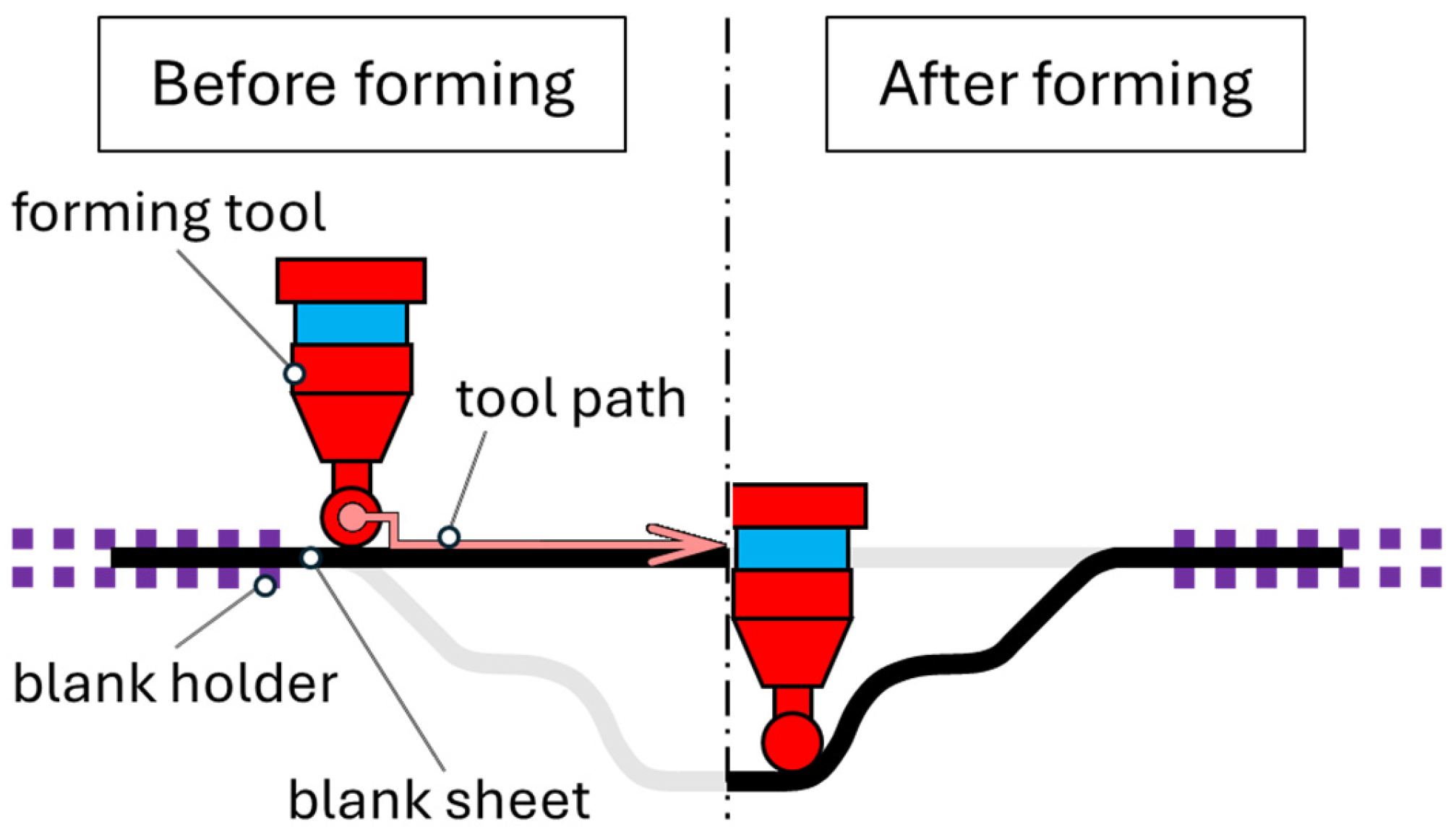
  • Single Point Incremental Forming (SPIF);
  • Two-Point Incremental Forming (TPIF);
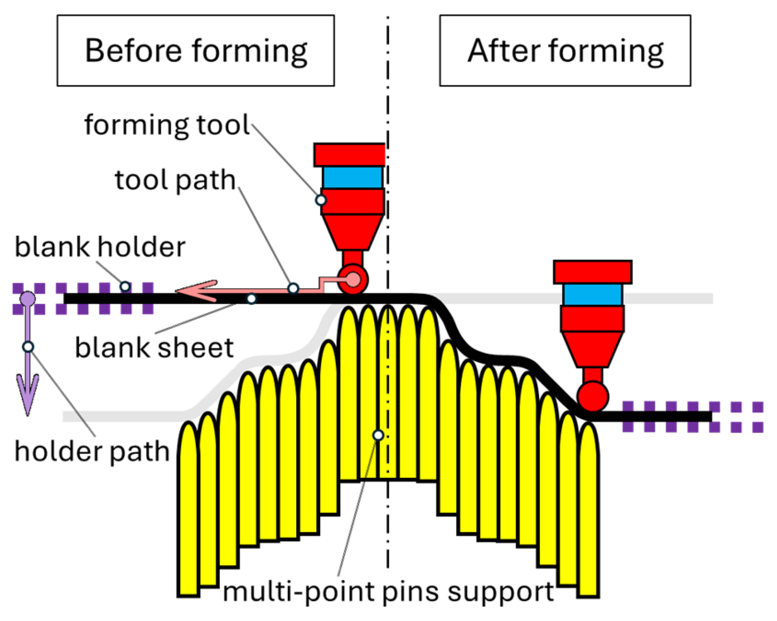
  • Multi-Point Incremental Forming (MPIF);
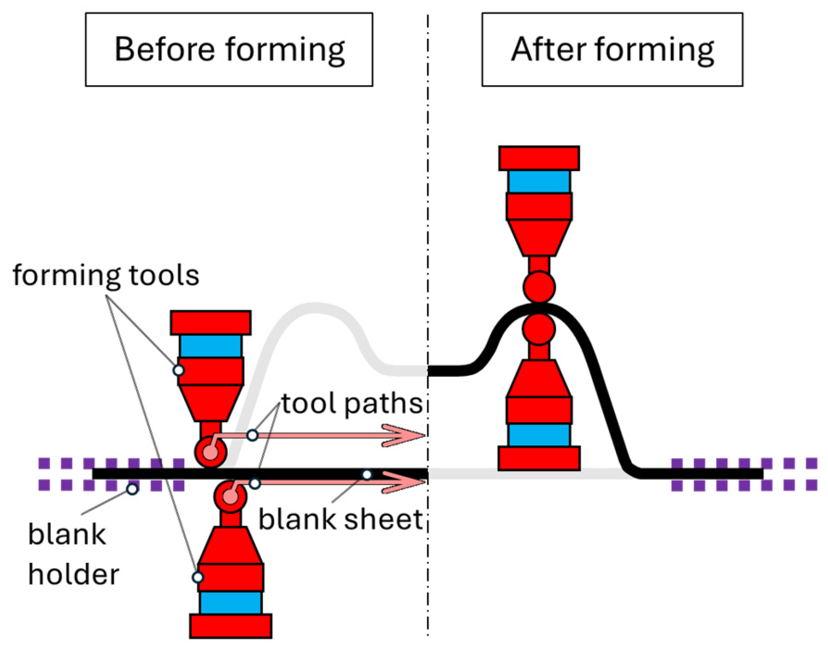
  • Double-Sided Incremental Forming (DSIF).
The SPIF process is one of the earliest methods developed in the field of incremental forming. The SPIF process is performed by using a tool with a rounded tip, applied with a CNC machine. It is a technique in which sheet metal is shaped into the desired product through a series of cascading incremental deformations. Research has shown that this process is not limited to forming metals but can also be applied to forming polymer and composite sheets [37,38].
The most basic method of this process involves clamping the sheet in an appropriate fixture and shaping it using a tool with a rounded tip, typically with a radius ranging from 5 to 20 mm. The tool is mounted in a tool holder on a CNC machine or, more commonly in modern applications, is attached to a robot or robotic arm. The tool presses into the sheet and follows the contour of the desired part, as shown in Figure 1. Upon completing the toolpath in the feed direction, the tool assumes a new depth, and the process is repeated until the desired geometry is achieved. The main advantage of this process is that it does not require a die. The absence of a die significantly influences the cost-effectiveness of manufacturing. It supports the production of highly customized or geometrically complex parts, ideal for prototyping and low-volume production.
The TPIF is a modified version of the SPIF process that achieves finer tolerances. In this process, the sheet is clamped in a holding device and incrementally formed using a tool of similar or the same geometry as in the SPIF process, moving between two predefined points, while incorporating a partial or full matrix. The partial matrix provides support only in essential parts of the workpiece, by using a countertool, while the full matrix provides support across the entire geometry of the workpiece (Figure 2). The partial matrix does not have the complete geometry of the workpiece, which allows it to be used for making several workpieces with different geometries, resulting in increased flexibility. The disadvantage of the partial matrix is the unfavorable loading, which can cause material failure during deformation. TPIF is a relatively new process in the metal forming industry, and thus there is a limited number of publications related to the process. Recent research projects focus on optimizing the tool path to improve surface quality, dimensional accuracy of parts, and to achieve a uniform distribution of sheet thickness across the product. The geometric accuracy of the TPIF process is higher than that of the SPIF process due to the smaller elastic recovery after unloading [39,40], and TPIF also enables the formation of more complex geometries.
The MPIF process is a hybrid process that combines two common manufacturing methods: Multi-Point Forming (MPF) and ISF. The basic concept of this procedure in the ISF process was first described by Li et al. (2009) [41]. Apart from the multi-point pin support tool, the basic components in the MPIF procedure are like those in the TPIF process. The multi-point pins are placed in fixed positions as shown in Figure 3. Each pin must be adjusted to the desired position before the shaping process begins. During the process, the forming tool moves along a pre-designed path, while the blank sheet is clamped using the sheet metal holder and moved down together. The movement of the sheet metal and the sheet holder should correspond to the path of the forming tool in the vertical direction. Compared to the conventional TPIF process, the MPIF process not only increases process flexibility but also reduces costs and shortens the time required for the forming process. The deformation of the material in the MPIF process closely corresponds to that in the TPIF process. A comparison between the MPIF and TPIF processes [42] shows that the thickness distributions and equivalent plastic deformations are very similar. However, dimples can easily appear on parts manufactured using the MPIF process due to discontinuous contact between the multi-point tool and the sheet metal.
As a result, the MPIF process leads to lower geometric precision and poorer surface finish compared to the TPIF process. Additional research in recent years has resulted in increased flexibility and improved accuracy of products obtained through this process [42,43,44,45,46].
DSIF is a process in which sheet metal is clamped vertically in a clamping device and formed using rounded tools, held by two opposing robotic arms (Figure 4). One robot is a “slave” and the other is a “master”. The use of two opposing robots, rather than one on a single side, helps achieve better surface quality and greater bending angles of the sheet, as the “slave” robot provides additional support. This procedure finds the widest application in RPT (rapid prototyping) procedures, i.e., rapid prototyping in the automotive and aerospace industries. DSIF is also used in the production of low-volume complex parts. The advantages of the process are increased symmetry of the workpiece (synchronized movement of two tools enables an improvement in the symmetry of the workpiece compared to the incremental forming process at one point), the possibility of applying higher shear speeds in the forming process (resulting in an increase in the efficiency of the process), flexibility (the DSIF process enables the production of extremely complex parts that are unachievable by conventional metal forming processes by deformation), no matrix is required (faster time production of the product because no time is spent on the construction and production of the matrix; the lack of a matrix results in an improvement in the economy of the process). The disadvantage of this process is the complexity of synchronized control of two tools (there are many influencing factors from clearance in the joints of the robotic arm to local imperfections of the material that are difficult to visualize), the required specialized equipment (requires two robots, a software package that will enable communication between the robots, an algorithm that will guide the robots and try to minimize possible errors in execution), and slow process (DSIF is a slow process that can have an impact on energy consumption) [47,48].

3.2. Classification by Type of Robot and System

ISF processes can be categorized based on the type of robotic systems employed. These classifications highlight the diverse robotic systems utilized in ISF, each offering unique advantages tailored to specific manufacturing requirements.
  • Robotic Arm (Manipulator-Based Forming);
  • Gantry Robotic Systems;
  • Hybrid Robotic Systems.
The Robotic Arm (Manipulator-Based Forming) approach utilizes a robotic arm equipped with a precisely controlled end-effector, such as a spherical or conical tool, to perform SPIF or TPIF. The flexibility and dexterity of robotic manipulators make them suitable for forming complex geometries. For instance, a study on robot-assisted incremental sheet metal forming demonstrated the use of a robotic manipulator to form steeper wall angle parts in a single pass, highlighting the capability of robotic arms in enhancing formability and precision in ISF processes [49].
Gantry Robotic Systems feature a gantry construction, providing a large working envelope suitable for handling larger material dimensions. Gantry systems are particularly advantageous for industrial-scale production of large parts due to their rigidity and precision. They offer overhead motion in multiple axes, facilitating the forming of sizable sheet metal components. For example, precision gantry stages or Cartesian robots are employed in various manufacturing processes requiring high accuracy and repeatability.
Hybrid Robotic Systems classification involves the integration of CNC machines and robotic systems to leverage the strengths of both technologies. The combination allows for the flexibility of robotic manipulators in performing complex operations, while CNC control ensures high precision and repeatability. Such hybrid systems are beneficial in ISF processes where intricate tool paths and adaptive forming strategies are required. A review of parallel-serial (hybrid) robotic manipulators discusses various architectures and applications, emphasizing the versatility and enhanced capabilities of hybrid systems in manufacturing [50].

3.3. Classification by Degree of Control

ISF processes can be classified based on the degree of control employed during the forming operation These classifications highlight the varying levels of control in ISF processes, each offering distinct advantages depending on the specific requirements of the manufacturing application.
  • Offline Programming;
  • Online Adaptive Forming;
  • Closed-Loop Forming.
Offline Programming: In this approach, forming operations are based on pre-generated CNC or CAD/CAM programs. This method is suitable for standardized and repeatable processes, where the forming path and parameters are predetermined and do not require real-time adjustments. The use of Offline Programming allows for efficient planning and simulation of the forming process, ensuring consistency and reducing setup times [51].
Online Adaptive Forming involves robots using sensors to provide feedback and adjust the tool in real time during the forming process. The advantages of Online Adaptive Forming include error reduction and better tracking of deformation, as the system can respond to variations in material properties or tool wear by making immediate adjustments. This adaptability enhances the robustness of the forming process, leading to improved part quality and reduced scrap rates [52].
Closed-Loop Forming combines sensors, such as optical or laser systems, for continuous geometry monitoring and tool control. This approach ensures high precision and quality by continuously monitoring the formed part and adjusting the forming parameters to maintain the desired geometry. The integration of advanced sensing technologies allows for real-time correction of deviations, leading to enhanced accuracy and surface finish in the final product [53].

3.4. Classification by Material Type and Sheet Thickness

ISF processes can be classified based on the material type and sheet thickness. These classifications highlight different approaches in ISF processes, each with specific requirements and challenges depending on the material type and sheet thickness [5,54,55].
  • Forming of Thin Sheets;
  • Forming of Thick Sheets;
  • Forming of Composite Materials.
Forming of Thin Sheets is suitable for materials such as aluminum, copper, or steel up to 2 mm thick. Applications include medical equipment and prototypes. Due to the thinness of the material, the forming process is less demanding, and the equipment requirements are lower. However, careful monitoring of process parameters is essential to prevent material damage.
Forming of Thick Sheets is used for tougher and thicker materials (e.g., over 4 mm). It requires stronger tools and robots due to the increased forces needed for forming. Thicker sheets allow for greater forming depths but also increase the demands for precision and process control. Optimizing parameters such as feed rate and temperature is crucial to achieve the desired product quality.
Forming of Composite Materials is specifically tailored for multi-layered structures. Composite materials often require specific forming conditions to prevent delamination or damage to layers. Using appropriate tools and controlling temperature are key to maintaining the integrity of the composite during the forming process.

3.5. Classification by Industrial Application of ISF

Flexibility of ISF, low tooling costs, and ability to work with various materials make it attractive for multiple industries. The application can be classified as follows [56,57]:
  • Prototyping;
  • Batch Production;
  • Customized Products.
ISF is ideal for rapid prototyping as it does not require expensive tools, unlike traditional methods such as stamping or deep drawing. This method enables the creation of complex geometries directly from CAD models. The automotive and aerospace industries often use this technique to develop prototypes of new parts.
ISF can be used for small-scale production runs, especially when standard methods are not cost-effective. For example, in producing batches of a few hundred parts, ISF offers significant savings as it eliminates tooling costs. It is used in industries producing limited-series parts, such as specialized machine components, automotive concepts, or parts for testing.
ISF is useful for producing personalized products, such as medical implants or components tailored to specific customer needs. Thanks to digitalization and direct integration with CAD models, unique components can be manufactured with high precision. An example can be the production of customized medical implants for facial bones or cranial applications. Figure 5 shows a sketch of an example of complex geometry obtained by ISF. Figure 6 shows a sketch of denture bases formed by ISF [58].

3.6. Classification by Integration of Technologies

Hybrid approaches enhance precision, enable the forming of difficult materials, and open up new applications across industries.
  • Laser-Assisted Forming—Heat-Assisted ISF;
  • Hybrid Additive and Incremental Processes;
  • ISF-Assisted Deep Drawing;
  • Ultrasonic-Assisted ISF (UAISF).
Heat-assisted incremental sheet forming (HA-ISF) is an advanced technique that combines localized heating with the incremental sheet forming process to improve formability and reduce forming forces, especially for hard-to-form materials. Key aspects of HA-ISF can include different heating methods like electric heating (applies electric current to heat the forming zone) and laser-assisted forming. Laser-assisted forming involves the integration of lasers into the incremental forming process [21,59]. The laser is used to locally heat the sheet metal, reducing its resistance to deformation and making the material more pliable. Localized heating enables more accurate control of the forming process. By softening the material in specific areas, residual stresses in the formed component are minimized. It allows for the forming of high-strength alloys and materials that are otherwise difficult to deform at room temperature [60].
The hybrid additive and incremental process combines additive manufacturing (AM) techniques, such as 3D printing, with ISF. The process begins by building up material layers using additive techniques, followed by robotic incremental forming to shape the material. AM enables the creation of tailored preforms with complex geometries, which are then refined using ISF. Hybrid processes minimize material waste by combining precise additive and subtractive techniques. They enable the use of a wide range of materials and design complexities [61,62,63].
The ISF-assisted deep drawing of the sheet metal, pre-cut to a specific shape, is placed on a concave die with its bottom supported. A tool presses down on the sheet from above, moving along the die to gradually form the material into the desired shape. The sheet’s bottom is held in place, preventing tilting and ensuring it maintains the intended form. For the circular part of the flange, the sheet is clamped between the female die and the tool. This clamping prevents the flange from spreading outward and helps maintain a more perpendicular angle between the curved flange section and the bottom of the part. This method allows for precise control over the forming process, especially for complex shapes with flanged edges [20].
UAISF is an advanced variation of the traditional incremental sheet forming (ISF) process that incorporates ultrasonic vibrations to enhance formability and reduce forming forces. The forming tool is connected to an ultrasonic transducer, which makes it vibrate in the vertical direction at ultrasonic frequencies. The tool moves along a pre-programmed path to form the desired shape, similar to traditional ISF. Ultrasonic vibrations cause localized softening of the material, making it more pliable and easier to deform. The main forming force is significantly reduced, typically by about 20% compared to conventional ISF. Ultrasonic energy facilitates the movement of dislocations within the material’s crystal structure, enhancing plasticity [64].

4. Key Process Parameters and Their Effects

The significance of knowing the influencing parameters is of great importance for the implementation of the optimal process. Using robots introduces a new set of difficulties. The robot is not an ideal rigid system, as such it is subject to deformation; these deformations affect the precision of the incremental deformation process and must be considered when making the product. Algorithms and machine learning are used to reduce this impact. Other influential parameters are the place of deformation of the sheet metal (if we are closer to the edge of the sheet where the clamping device is, then the stress conditions have changed), the shape of the tool, the shear speed, the lubricants used, the rotation of the tool, the tool control (it is necessary to coordinate the movement of the two robots during the DSIF process), elastic spring-back of the material, etc. The six basic and most important parameters are tool geometry, tool path, feed speed, tool rotation frequency, vertical step size (incremental depth), and forming angle. These six parameters were chosen as the most important because of the greatest impact on the implementation of the procedure. Other parameters vary according to the type of geometry of the workpiece, the material, and the choice of technology [65,66,67].

4.1. Tool Geometry

The size and shape of the tool is an important factor in the formability of materials in ISF processes. Experiments have shown that a tool with a smaller radius of curvature provides greater formability than a tool with a larger radius. The use of tools with a larger radius of curvature allows for better support of the sheet metal when forming due to the larger area of the contact zone. The use of tools with a larger radius of curvature also results in an increase in the deformation force due to the increase in the contact zone between the tool and the workpiece. A tool with a smaller curvature radius achieves better formability of the material due to the high concentration of the strain zone, which causes more stress and results in better formability. An additional reason increased formability has been observed when using tools with a smaller curvature radius is friction at the tip of the tool, which results in heat development and an increase in the temperature at which the process is carried out. Reducing the rounding radius of the tool can also have a negative impact. It has been proven that by reducing the radius of curvature from 10 mm to 5 mm, the material forming limit is reduced. Using a 5 mm diameter tool results in higher precision, but material thinning exceeds 20%. A 10 mm diameter tool reduces thinning to approximately 10% at the cost of slightly lower accuracy [68].

4.2. Tool Path

The path of the tool is also considered an important parameter of the ISF process. The tool path defines the movement of the tool along a given contour; therefore, it influences the contact conditions between the tool and the sheet. Contact conditions are critical for the distribution of stress and loads, which directly influence the formability of the material and the precision of the process. The simplest strategies for tool paths are step-by-step and spiral paths. Tool paths are determined using CAM software. Depending on the geometry of the object and the initial thickness of the sheet, the beginning of the tool’s path should start from the edges of the product in order to achieve the best possible final shape. It is also better to apply a curved tool path strategy (simultaneous movement of the tool in horizontal and vertical directions) in order to achieve a uniform distribution of sheet thickness. Deformation of the sheet takes place only at the tip of the tool in the contact zone with the sheet, where the sheet is subject to tensile deformation. Such a deformation scheme results in a decrease in the thickness of the sheet and a decrease in the cross-section of the sheet, which is not desirable. To reduce the impact of such deformation, sheet metal deformation is performed in steps.

4.3. Feed Speed

The feed speed has an impact on the friction conditions between the tool and the sheet, and the influence on the sheet loads. When testing the influence of feed speed, it was observed that during the use of feed speed from 1200 mm/s to 4000 mm/s, the formability of the material was reduced. It is believed that the reduction in the material formability is the result of hardening. Aluminum alloys do not react significantly to an increase in feed speed, so feed speed has less influence on their formability. Feed speeds around 800 mm/min offer a balance between speed and part quality in steel forming [67].

4.4. Tool Rotation Frequency

The influence of the tool rotation frequency has a great influence on the implementation of the process. Friction occurs on the contact surface between the tool and the sheet, which can be affected by the frequency of the rotation of the tool. Friction generates heat that affects the microstructure of the material and the quality of the surface. Research on the influence of the rotational frequency of the tool has shown that from 0 to 1000 rpm, friction prevails, and as the rotational frequency is increased to 2000 to 7000 rpm, the influence of heat becomes predominant. It has also been observed that increasing the frequency of rotation resulted in increased formability of the material. That is why optimization is necessary.

4.5. Vertical Step Size

The vertical step (incremental depth) refers to the depth that the tool takes during the grip and pass. The impact of the vertical step has not yet been fully explored. Theoretical research conducted on the influence of the vertical step has shown that negative load distribution occurs under the tool, and tensile stresses occur on the walls of the workpiece. With the reduction in the vertical step, the previously mentioned loads are also reduced. Research [63] has shown that during incremental sheet metal forming, the vertical step has a significant impact on the formability of the material. Reducing the vertical step increased the likelihood of forming the desired product and improving surface quality but also resulted in longer processing time. Smaller step sizes (e.g., 0.2 mm) enhance surface finish and reduce spring-back; larger step sizes (e.g., 1 mm) accelerate the process but may compromise dimensional accuracy [68].

4.6. Forming Angle

The maximum forming angle in incremental forming is considered one of the most important criteria when determining the formability of a material. Studies have shown that the influence of the vertical step size had little effect on the maximum achievable shaping angle. The radius of tool rounding and the initial thickness of the sheet metal had a greater influence on this parameter. The angles that are achievable by incremental forming of the aluminum sheet range from 63° to 66° [69]; when forming steel sheets, an angle of 80° is achieved [70]. With the increase in the radius of tool rounding, the size of the tool and the size of the vertical step, and the decrease in the thickness of the sheet metal, a decrease in the maximum achievable angle of forming was recorded. Feed speed has no significant effect on this parameter. Experiments have shown that the curved path of the tool results in a more achievable forming angle.

5. Control Processes in ISF—Roboforming

The measurement and control systems used in the roboforming process include a large number of sensors and instruments for monitoring dimensions and shapes, deformations, forces, temperatures, and other key parameters during the forming process. These systems are essential for ensuring sustainability, as they enable resource optimization, waste reduction, and energy efficiency, ultimately increasing overall process effectiveness and reducing negative environmental impact.
Dimension and shape monitoring systems scan and monitor the shape of the workpiece in real time [71,72]. Force and movement sensors are installed between the robotic arm and the tool, enabling monitoring of changes in forces and torques, detecting overloads and preventing damage to tools or materials. They are also used for feedback control and real-time process adjustment. Deformation sensors measure local deformations of sheet metal, such as stretching or bending. Temperature sensors record the temperature distribution both on the surface and inside the sheet metal and tool during the process. Accelerometers and vibration sensors measure vibrations of the robotic arm and tools to avoid errors caused by dynamic instabilities and analyze system stability during forming [73,74,75].
Roboforming is a very complex metal forming technology that involves complex interactions between robots, tools, materials and sensors. Each of these elements affects the accuracy, precision, and reliability of measurement results. Despite extensive research aimed at identifying and quantifying factors influencing measurement accuracy, standardized procedures for evaluating accuracy and precision are not yet established. Regular calibration of measurement systems in roboforming is necessary and is a key part of maintaining the quality and reliability of the process. The calibration procedure is defined as an operation that, under specified conditions, in a first step, establishes a relation between the quantity values with measurement uncertainties provided by measurement standards and corresponding indications with associated measurement uncertainties and, in a second step, uses this information to establish a relation for obtaining a measurement result from an indication [76]. Although the main goal of roboforming is to achieve results and product quality within specifications, from a metrological point of view, measurement uncertainty is an indispensable parameter that speaks about the quality of measurement results, ensures confidence in the measurement result and significantly affects the risks of accepting a non-compliant product or not accepting a compliant product.
Due to the complexity of roboforming, multiple sources of uncertainty are present, making it challenging to evaluate measurement uncertainty. Real-time measurements are subject to dynamic influences such as vibration, friction, and thermal expansion, which further complicates the estimation of uncertainty. Although the calibration procedures for individual measurement systems are described in the literature, no research has yet been conducted to determine the measurement uncertainty of measurement results in the roboforming process.
The calibration of measurement systems ensures optimal system functionality and contributes to sustainable production by reducing waste, increasing efficiency, and minimizing the risk of errors.
Industrial roboforming processes are relatively new, and a detailed assessment of measurement uncertainty will require additional measurement instruments, sophisticated tools and data processing, user and engineer education as well as promoting awareness of the importance of expressing measurement uncertainty in industrial applications.

6. Sustainability Considerations in ISF

ISF is broadly recognized for its superior flexibility, cost-effectiveness, and faster production times compared to traditional methods. In addition, these technologies represent a clear step towards Industry 5.0 by increasing the human-centric approach through the adaptation of products to the specific needs of the customer [77] and encourage the sustainability of production. However, literature lacks extensive assessments of this process’s sustainability. Some researchers have attempted to address this gap. For example, in [78], a comparative analysis highlights the sustainability aspects of incremental forming versus stamping. Although incremental forming requires more deformation energy than stamping, it can achieve material savings.
Research in [79] compares the energy requirements of conventional stamping and incremental deformation by producing identical parts using both processes. While incremental forming involves longer processing times and higher energy consumption, reducing the incremental step size can mitigate energy use. The environmental aspects, such as energy expenditure, tooling usage, metal waste, recycling potential, and carbon footprint, were also analyzed. Incremental forming stands out for its energy efficiency and adaptability in manufacturing customized parts, though its longer processing times must be considered.
Another study [80] delves into sustainability by analyzing energy consumption, including deformation energy, electricity usage, and a comparison with the energy demands of stamping. It also evaluates the environmental impacts, such as CO2 emissions, optimal batch sizes, and material efficiency. The study suggests future strategies to lower energy use, including minimizing idle times and designing high-efficiency equipment.
Another study [81] evaluates incremental forming regarding power needs, energy usage, costs, CO2 emissions, production times, and material efficiency. The findings indicate that incremental forming is more sustainable than conventional methods, particularly for small production runs like prototypes. Process sustainability can be enhanced by optimizing parameters such as spindle speeds, feed rates, and step sizes. Additionally, improved tool paths and energy-efficient machinery could further enhance the process’s performance.

7. Process Optimization

Based on the data available in the literature, it is possible to recommend certain optimizations of process parameters and system characteristics. This section delves into the key improvements across the major systems of ISF, including control, mechanical, and measurement systems.

7.1. Control System

The advancements in control systems for incremental sheet forming (ISF) have significantly improved process precision and efficiency. Smart control systems enhanced by real-time data processing should enable the following:
  • Continuous monitoring of forming forces and sheet thickness;
  • Adaptive adjustment of tool paths based on real-time feedback;
  • Predictive maintenance to minimize downtime.
These improvements allow for more accurate forming, reduced material waste, and increased efficiency.

7.2. Mechanical System

Mechanical systems can expand the capabilities of ISF:
  • Multi-axis CNC machines specifically designed for ISF allow for more complex geometries.
  • Hybrid ISF systems combining traditional forming with other processes like laser heating expand its possibilities.
  • Implementation of robotic arms increases flexibility and larger working envelopes.

7.3. Measurement System

Adequate measurement systems enhance the accuracy and quality control of ISF processes. Therefore, the recommendations for improvements would aim towards the following:
  • Integration of in situ 3D scanning for real-time geometry verification;
  • Development of force sensors for precise control of forming pressure;
  • Implementation of thermal imaging for temperature monitoring in warm/hot ISF processes.

7.4. Tool Head Selection

Tool head selection significantly impacts the forming process:
  • Smaller tool diameters (e.g., 5 mm) generally produce higher geometric accuracy but increase the risk of material thinning.
  • Larger tool diameters (e.g., 10 mm) reduce thinning but may compromise accuracy.
  • Rotating geometry tools can improve surface finish and reduce forming forces compared to rigid tools.

7.5. Process Parameters

Key process parameters must be optimized based on the material and part requirements:
  • Feed speed: Higher rates (e.g., 1500 mm/min) increase efficiency but may compromise surface quality.
  • Vertical step size: Smaller steps (e.g., 0.2 mm) enhance surface finish but increase forming time.
  • Spindle speed: Optimal speeds vary by material, with aluminum alloys performing best at 2000–3000 RPM [55].

7.6. Material Considerations

Different materials require specific parameter adjustments:
  • Aluminum alloys: Commonly used due to their formability, requiring careful control of forming speed and temperature.
  • Titanium alloys: May require preheating or special lubricants to prevent cracking.
  • Steel sheets: Often used for industrial applications, necessitating higher forming forces [82].

7.7. Part Type Influence

The geometry and function of the part also dictate parameter selection:
  • Complex shapes may require multi-stage forming strategies with varying tool paths.
  • Parts with high accuracy requirements might need smaller tool diameters and step sizes.
  • Large parts may benefit from robotic ISF systems for increased working volume [83].
By considering these factors in combination, manufacturers can optimize the ISF process for specific materials and part types, ensuring high-quality outcomes while maximizing efficiency.

8. Further Research Directions

Based on the comprehensive review of incremental sheet forming (ISF) technologies and their development towards Industry 5.0 principles, several key areas emerge as promising directions for further research.
Optimization of production parameters based on the control process:
  • Focus research on the full integration of measurement systems with autonomous robotic platforms that will make decisions in real time.
  • Develop measurement systems that will meet the requirements of flexible manufacturing in a way that will enable rapid adaptation to different materials, shapes, and production batches.
  • New measurement systems should be more resistant to vibrations, temperature, and electromagnetic interference in order to maintain accuracy and precision even in demanding conditions.
  • To monitor environmental impact, it is necessary to establish measurement systems that will measure emissions and other parameters related to sustainability, ensuring compliance with environmental standards.
  • Develop and standardize methods for assessing measurement uncertainty in roboforming. Adopt international standards and software for assessing measurement uncertainty and implement advanced tools for uncertainty assessment and automatic inclusion in results.
The future of measurement systems in roboforming lies in the integration of advanced technologies, automation, and sustainability. Quality measurement systems are key tools for achieving high product quality with minimal resources, reducing waste and yielding environmentally friendly production. It is necessary to educate users and engineers to promote awareness of the importance of expressing measurement uncertainty in industrial applications.

9. Conclusions

The development of ISF technologies, particularly within the context of roboforming, demonstrates significant potential for integrating the principles of Industry 5.0, including personalization, sustainability, and an ethical approach to manufacturing. A historical review highlights the accelerated evolution of these technologies, with key innovations involving advanced robotic systems, hybrid processes such as ISF combined with deep drawing, ultrasonic-assisted ISF, and the use of localized heating to improve material formability.
Despite notable advantages such as waste reduction, process flexibility, and adaptability for producing complex components, challenges remain. These include the need to reduce processing time, improve surface quality, and explore sustainable materials and methods. Addressing these challenges requires further automation, process optimization, and the integration of advanced technologies, for real-time parameter control during forming.
Enhancing the sustainability of ISF processes involves multiple strategies. First, optimizing forming parameters, such as tool paths, feed rates, and step sizes, can significantly reduce energy consumption. Second, integrating renewable energy sources into manufacturing facilities and employing energy-efficient robotics can minimize the carbon footprint of production. Third, increasing the recyclability of materials through the use of biodegradable composites or metals with higher recycling rates aligns with circular economy principles. Additionally, adopting closed-loop monitoring and feedback systems can help ensure minimal waste and consistent quality, while innovative hybrid methods, such as combining additive and incremental forming, provide opportunities for reducing material use without compromising performance.
ISF processes, with their emphasis on sustainability and innovation, represent a significant step toward ethical and environmentally responsible manufacturing, aligning closely with the goals of Industry 5.0. Future research should focus on integrating measurement systems for monitoring emissions and energy efficiency, standardizing methods for assessing measurement uncertainty, and advancing tools for real-time process adjustments. Such developments will enhance trust in outcomes, improve process precision, and contribute to the broader sustainability objectives of modern manufacturing systems.

Author Contributions

Conceptualization, Z.K.; methodology, Z.K. and P.P.; writing—original draft preparation, Z.K., B.R. and P.P.; validation, B.R., P.P. and A.R.; writing—review and editing, P.P., B.R. and A.R.; formal analysis, A.R.; investigation, Z.K. All authors have read and agreed to the published version of the manuscript.

Funding

This research received no external funding.

Conflicts of Interest

The authors declare no conflicts of interest.

References

  1. Meier, H.; Buff, B.; Laurischkat, R.; Smukala, V. Increasing the Part Accuracy in Dieless Robot-Based Incremental Sheet Metal Forming. CIRP Ann. 2009, 58, 233–238. [Google Scholar] [CrossRef]
  2. Jeswiet, J.; Geiger, M.; Engel, U.; Kleiner, M.; Schikorra, M.; Duflou, J.; Neugebauer, R.; Bariani, P.; Bruschi, S. Metal Forming Progress since 2000. CIRP J. Manuf. Sci. Technol. 2008, 1, 2–17. [Google Scholar] [CrossRef]
  3. Jeswiet, J. Incremental Single Point Forming. Trans. NAMRI/SME 2001, 29, 75–79. [Google Scholar]
  4. Toshev, R.; Bengs, D.; Helo, P.; Zamora, M. Advancing Free-Form Fabrication: Industrial Robots’ Role in Additive Manufacturing of Thermoplastics. Procedia Comput. Sci. 2024, 232, 3131–3140. [Google Scholar] [CrossRef]
  5. Emmens, W.C.; Sebastiani, G.; Van Den Boogaard, A.H. The Technology of Incremental Sheet Forming—A Brief Review of the History. J. Mater. Process. Technol. 2010, 210, 981–997. [Google Scholar] [CrossRef]
  6. Çerlek, Ö.; Akin, Y.; Tüylü, A. Incremental Sheet Metal Forming Method. In Special Issues in Material and Energy Sciences; Bridge Publications: Commerce, CA, USA, 2023; pp. 5–19. [Google Scholar]
  7. Edward, L. Apparatus and Process for Incremental Dieless Forming. U.S. Patent 3,342,051, 19 September 1967. [Google Scholar]
  8. Berghahn, W.G.; Murray, J.G.F. Method of Dielessly Forming Surfaces of Revolution. U.S. Patent 3,316,745, 2 May 1967. [Google Scholar]
  9. Hadoush, A. Efficient Simulation and Process Mechanics of Incremental Sheet Forming. Ph.D. Thesis, University of Twente, Enschede, The Netherlands, 2010. [Google Scholar]
  10. Mason, B. Sheet Metal Forming for Small Batches. Bachelor’s Thesis, University of Nottingham, Nottingham, UK, 1978. [Google Scholar]
  11. Pathak, J. A Brief Review of Incremental Sheet Metal Forming. Int. J. Latest Eng. Manag. Res. 2017, 2, 35–43. [Google Scholar]
  12. Matsubara, S. Method and Device for Forming Metal Plate. JPH07132329A, 23 May 1995. [Google Scholar]
  13. Shima, A.; Yoshikawa, T.; Nakamura, K.; Suda, Y.; Suzuki, S. Formation of Successively Expanding Metallic Plate and Apparatus Therefore. JPH0985355A, 31 March 1997. [Google Scholar]
  14. Ueno, K.; Matsuda, F.; Nagata, T.; Yamamoto, K.; Murata, A.; Nonoyama, F. Incremental Molding Method. JPH10137858A, 26 May 1998. [Google Scholar]
  15. Waratani, K.; Yoshikawa, T.; Nakamura, K.; Shima, A.; Endo, H.; Tajima, Y.; Suzuki, S.; Misdeki, T. Method for Continuously and Successively Bulging Metal Sheet and Device Therefore. WO2009053323A3, 20 October 2008. [Google Scholar]
  16. Ueno, K.; Matasuda, F.; Nagata, T.; Yamamoto, K.; Atsunobu, M.; Nonioyama, F. Male Die Forming Method of Metal Sheet. JP 10-314855, 22 May 1997. [Google Scholar]
  17. Ochiai, I.; Momoiyama, K.; Onawa, T.; Suzuki, S.; Miseki, T. Formation of Metallic Plate and Forming Tool. JP 11-285741, 3 April 1998. [Google Scholar]
  18. Murata, A.; Matsuda, F. Incremental Pressing and Forming Device. JP 2000-153313, 16 November 1998. [Google Scholar]
  19. Tuominen, T. Method and Apparatus for Forming Three-Dimensional Shapes in a Sheet Metal. JP 2004-291067, 21 October 2004. [Google Scholar]
  20. Okada, N.; Kawamura, W. Incremental Forming Method and Apparatus for the Same. JP 2006-051547, 17 April 2001. [Google Scholar]
  21. Okada, N.; Ro, G.; Suzuki, Y. Method and Apparatus for Incremental Forming. JP 2004-291065, 21 October 2004. [Google Scholar]
  22. Callebaut, B.; Duflou, J.; Verbert, J. Asymmetric Incremental Sheet Forming System. EP 1 899 089 A2, 26 July 2011. [Google Scholar]
  23. Klocke, F.; Wehrmeister, T. Laser-Assisted Metal Spinning of Advanced Materials. In Proceedings of the Second International WLT-Conference on Lasers in Manufacturing, Munich, Germany, 24 June 2003; pp. 195–200. [Google Scholar]
  24. Park, J.G.; You, B.S.; Kim, Y.S. A parametric Study in Incremental Forming of Magnesium Alloy Sheet. Trans. Mater. Process. 2008, 17, 412–419. [Google Scholar] [CrossRef]
  25. Kiridena, V.S.; Xia, Z.C. Method of Incrementally Forming a Workpiece. CN102343386A, 8 February 2012. [Google Scholar]
  26. Johnson, C.F.; Kiridena, V.S.; Ren, F.; Xia, Z.C. System and Method for Incrementally Forming a Workpiece. US8322176B2, 4 December 2012. [Google Scholar]
  27. Ren, F.; Xia, Z.C. Method to Improve Geometrical Accuracy of an Incrementally Formed Workpiece. US8783078B2, 2 February 2012. [Google Scholar]
  28. Cao, J.; Malhotra, R. System and Method for Accumulative Double Sided Incremental Forming. US9168580B2, 25 April 2013. [Google Scholar]
  29. Roth, J.; Cao, J. Electrical-Assisted Double Side Incremental Forming and Processes Thereof. US20120055217A1, 8 March 2012. [Google Scholar]
  30. Nonomura, K.; Kurozumi, K.; Inoue, K. Incremental Forming Method. US 6,561,002 B2, 13 May 2016. [Google Scholar]
  31. Ndip-Agbor, E.E.; Cao, J. Automated Toolpath Generation Method for Double Sided Incremental Forming. US20170227947A1, 25 December 2018. [Google Scholar]
  32. Ilinich, A.; Luckey, S.G.; Gillard, A.J.; Kiridena, V.S. Method to Reduce Tool Marks in Incremental Forming. US0030585A1, 17 August 2021. [Google Scholar]
  33. Asano, R.; Sada, K.; Oyamada, K.; Hamano, S.; Ishizaki, S.; Nagai, K. Incremental Forming Method. JP2024137168A, 10 July 2024. [Google Scholar]
  34. Trzepieciński, T.; Najm, S.M.; Oleksik, V.; Vasilca, D.; Paniti, I.; Szpunar, M. Recent Developments and Future Challenges in Incremental Sheet Forming of Aluminium and Aluminium Alloy Sheets. Metals 2022, 12, 124. [Google Scholar] [CrossRef]
  35. Lu, B.; Fang, Y.; Xu, D.K.; Chen, J.; Ou, H.; Moser, N.H.; Cao, J. Mechanism Investigation of Friction-Related Effects in Single Point Incremental Forming Using a Developed Oblique Roller-Ball Tool. Int. J. Mach. Tools Manuf. 2014, 85, 14–29. [Google Scholar] [CrossRef]
  36. Strano, M. Technological Representation of Forming Limits for Negative Incremental Forming of Thin Aluminum Sheets. J. Manuf. Process. 2005, 7, 122–129. [Google Scholar] [CrossRef]
  37. Schafer, T.; Schraft, R. Incremental Sheet Metal Forming by Industrial Robots. Rapid Prototyp. J. 2005, 11, 278–286. [Google Scholar] [CrossRef]
  38. Trzepieciński, T.; Krasowski, B.; Kubit, A.; Wydrzyński, D. Possibilities of Application of Incremental Sheet-Forming Technique in Aircraft Industry. Adv. Mech. Mater. Eng. 2018, 35, 87–100. [Google Scholar] [CrossRef]
  39. Safari, M. Two point incremental forming of a complicated shape with negative and positive dies. Iran. J. Mater. Form. 2017, 4, 51–61. [Google Scholar] [CrossRef]
  40. Jeswiet, J.; Duflou, J.R.; Szekeres, A. Forces in Single Point and Two Point Incremental Forming. Adv. Mater. Res. 2005, 6–8, 449–456. [Google Scholar] [CrossRef]
  41. Li, X.J.; Li, M.Z.; Liu, C.G.; Cai, Z.Y. Principle and Simulation Study on Multi Point-Single Point Incremental Combined Forming for Sheet Metal. Mater. Sci. Forum 2009, 626–627, 273–278. [Google Scholar] [CrossRef]
  42. Nourmohammadi, A.A.; Elyasi, M.; Mirnia, M.J. Flexibility Improvement in Two-Point Incremental Forming by Implementing Multi-Point Die. Int. J. Adv. Manuf. Technol. 2019, 102, 2933–2952. [Google Scholar] [CrossRef]
  43. Ramkumar, K.; Baskar, N.; Elangovan, K.; Narayanan, C.S.; Selvarajan, K.A.; Jesuthanam, C.P. Comparison of Multi Point Incremental Forming Tool with Single Point Incremental Forming Tool Using FLD, Fractography and 3D-Surface Roughness Analysis on Cr/Mn/Ni/Si Based Stainless Steel. Silicon 2021, 13, 487–494. [Google Scholar] [CrossRef]
  44. Ramkumar, K.; Selvarajan, K.A.; Narayanan, C.S.; Bejaxhin, A.B.H. Performance Analysis of Multi-Point Incremental Forming Tool Using Martensitic AISI 420 Sheet Metals. Arch. Metall. Mater. 2024, 69, 326–366. [Google Scholar] [CrossRef]
  45. Boudhaouia, S.; Gahbiche, M.A.; Ayed, Y.; Giraud, E.; Ben Salem, W.; Dal Santo, P. Experimental and Numerical Study of a New Hybrid Process: Multi-Point Incremental Forming (MPIF). Int. J. Mater. Form. 2018, 11, 815–827. [Google Scholar] [CrossRef]
  46. Zhao, X.; Ou, H. A New Flexible Multi-Point Incremental Sheet Forming Process with Multi-Layer Sheets. J. Mater. Process. Technol. 2023, 322, 118214. [Google Scholar] [CrossRef]
  47. Peng, W.; Ou, H.; Becker, A. Double-Sided Incremental Forming: A Review. J. Manuf. Sci. Eng. 2019, 141, 050802. [Google Scholar] [CrossRef]
  48. Moser, N.; Leem, D.; Ehmann, K.; Cao, J. A High-Fidelity Simulation of Double-Sided Incremental Forming: Improving the Accuracy by Incorporating the Effects of Machine Compliance. J. Mater. Process. Technol. 2021, 295, 117152. [Google Scholar] [CrossRef] [PubMed]
  49. Mohanty, S.; Regalla, S.P.; Daseswara Rao, Y.V. Robot-Assisted Incremental Sheet Metal Forming under the Different Forming Condition. J Braz. Soc. Mech. Sci. Eng. 2019, 41, 74. [Google Scholar] [CrossRef]
  50. Antonov, A. Parallel–Serial Robotic Manipulators: A Review of Architectures, Applications, and Methods of Design and Analysis. Machines 2024, 12, 811. [Google Scholar] [CrossRef]
  51. Belchior, J.; Guillo, M.; Courteille, E.; Maurine, P.; Leotoing, L.; Guines, D. Off-Line Compensation of the Tool Path Deviations on Robotic Machining: Application to Incremental Sheet Forming. Robot. Comput.-Integr. Manuf. 2013, 29, 58–69. [Google Scholar] [CrossRef]
  52. Thiery, S.; Zein El Abdine, M.; Heger, J.; Ben Khalifa, N. Closed-Loop Control of Product Geometry by Using an Artificial Neural Network in Incremental Sheet Forming with Active Medium. Int. J. Mater. Form. 2021, 14, 1319–1335. [Google Scholar] [CrossRef]
  53. Nallagundla, V.R.; Lingam, R.; Cao, J. Incremental Sheet Metal Forming Processes. In Handbook of Manufacturing Engineering and Technology; Nee, A., Ed.; Springer: London, UK, 2014; pp. 1–37. ISBN 978-1-4471-4976-7. [Google Scholar]
  54. Tisza, M. General Overview of Sheet Incremental Forming. J. Achiev. Mater. Manuf. Eng. 2012, 55, 113–120. [Google Scholar]
  55. Popp, G.-P.; Racz, S.-G.; Breaz, R.-E.; Oleksik, V.S.; Popp, M.-O.; Morar, D.-E.; Chicea, A.-L.; Popp, I.-O. State of the Art in Incremental Forming: Process Variants, Tooling, Industrial Applications for Complex Part Manufacturing and Sustainability of the Process. Materials 2024, 17, 5811. [Google Scholar] [CrossRef]
  56. Schuh, G.; Bergweiler, G.; Fiedler, F.; Bickendorf, P.; Colag, C. A Review on Flexible Forming of Sheet Metal Parts. In Proceedings of the 2019 IEEE International Conference on Industrial Engineering and Engineering Management (IEEM), Macao, China, 15–18 December 2019; pp. 1221–1225. [Google Scholar]
  57. Bhoyar, P.K.; Borade, A.B. The Use of Single Point Incremental Forming for Customized Implants of Unicondylar Knee Arthroplasty: A Review. Res. Biomed. Eng. 2015, 31, 352–357. [Google Scholar] [CrossRef]
  58. Milutinović, M.; Lenđel, R.; Potran, M.; Vilotić, D.; Skakun, P.; Plančak, M. Application of Single Point Incremental Forming for Manufacturing of Denture Base. Adv. Technol. Mater. 2014, 39, 15–24. [Google Scholar]
  59. Li, W.; Attallah, M.M.; Essa, K. Heat-Assisted Incremental Sheet Forming for High-Strength Materials—A Review. Int. J. Adv. Manuf. Technol. 2023, 124, 2011–2036. [Google Scholar] [CrossRef]
  60. Göttmann, A.; Diettrich, J.; Bergweiler, G.; Bambach, M.; Hirt, G.; Loosen, P.; Poprawe, R. Laser-Assisted Asymmetric Incremental Sheet Forming of Titanium Sheet Metal Parts. Prod. Eng. Res. Dev. 2011, 5, 263–271. [Google Scholar] [CrossRef]
  61. Ge, T.; Li, Y.; Gao, D.; Yang, C.; Li, F. Hybridizing Additive Manufacturing and Sheet Forming Process to Manufacture Complex Components with Multi-Features: A Review. J. Manuf. Process. 2024, 124, 345–364. [Google Scholar] [CrossRef]
  62. Cherukupally, S.; Nagallapati, V.; Konka, P.; Simhambhatla, S.; Nallagundla, V.R. Brief Paper: Judicious Hybridization of Incremental Forming and Additive Manufacturing to Enhance Product Complexity Through Non-Planar Substrate/Deposition. In Proceedings of the International Manufacturing Science and Engineering Conference, Knoxville, TN, USA, 17–21 June 2024. [Google Scholar]
  63. Ambrogio, G.; Gagliardi, F.; Muzzupappa, M.; Filice, L. Additive-Incremental Forming Hybrid Manufacturing Technique to Improve Customised Part Performance. J. Manuf. Process. 2019, 37, 386–391. [Google Scholar] [CrossRef]
  64. Cheng, R. Investigation of Acoustic Softening and Its Application in Ultrasonic Assisted Incremental Sheet Forming. Ph.D. Thesis, University of Michigan, Ann Arbor, MI, USA, 2022. [Google Scholar]
  65. Kim, Y.H.; Park, J.J. Effect of Process Parameters on Formability in Incremental Forming of Sheet Metal. J. Mater. Process. Technol. 2002, 130–131, 42–46. [Google Scholar] [CrossRef]
  66. Patel, D.; Gandhi, A. A Review Article on Process Parameters Affecting Incremental Sheet Forming (ISF). Mater. Today Proc. 2022, 63, 368–375. [Google Scholar] [CrossRef]
  67. Ai, S.; Lu, B.; Chen, J.; Long, H.; Ou, H. Evaluation of Deformation Stability and Fracture Mechanism in Incremental Sheet Forming. Int. J. Mech. Sci. 2017, 124–125, 174–184. [Google Scholar] [CrossRef]
  68. Ghazi, S.K.; Salloom, M.Y.; Bedan, A.S. Experimental Evaluation of a System to Control the Incremental Forming of Aluminum Alloy Type 1050. Eng. Technol. Appl. Sci. Res. 2024, 14, 16943–16949. [Google Scholar] [CrossRef]
  69. Ham, M.; Jeswiet, J. Single Point Incremental Forming and the Forming Criteria for AA3003. CIRP Ann. 2006, 55, 241–244. [Google Scholar] [CrossRef]
  70. Crina, R. Determination of the Maximum Forming Angle of Some Carbon Metal Sheets. J. Eng. Stud. Res. 2011, 17, 71. [Google Scholar]
  71. Ambrogio, G.; Costantino, I.; De Napoli, L.; Filice, L.; Fratini, L.; Muzzupappa, M. Influence of Some Relevant Process Parameters on the Dimensional Accuracy in Incremental Forming: A Numerical and Experimental Investigation. J. Mater. Process. Technol. 2004, 153–154, 501–507. [Google Scholar] [CrossRef]
  72. Lingam, R.; Bansal, A.; Reddy, N.V. Analytical Prediction of Formed Geometry in Multi-Stage Single Point Incremental Forming. Int. J. Mater. Form. 2016, 9, 395–404. [Google Scholar] [CrossRef]
  73. Gatea, S.; Ou, H.; McCartney, G. Review on the Influence of Process Parameters in Incremental Sheet Forming. Int. J. Adv. Manuf. Technol. 2016, 87, 479–499. [Google Scholar] [CrossRef]
  74. Paul, E.; Bharti, S.; Uthama, A.; Boby, R.A.; Krishnaswamy, H.; Klimchik, A. Evaluation of Deviations Due to Robot Configuration For Robot-Based Incremental Sheet Metal Forming. In Proceedings of the 2023 6th International Conference on Advances in Robotics, Rupnagar, India, 5–8 July 2023; Association for Computing Machinery: New York, NY, USA, 2023; pp. 1–6. [Google Scholar]
  75. Bharti, S.; Paul, E.; Uthaman, A.; Krishnaswamy, H.; Klimchik, A.; Abraham Boby, R. Systematic Analysis of Geometric Inaccuracy and Its Contributing Factors in Roboforming. Sci. Rep. 2024, 14, 20291. [Google Scholar] [CrossRef]
  76. JCGM. International Vocabulary of Metrology—Basic and General Concepts and Associated Terms. Chem. Int. Newsmag. IUPAC 2008, 30, 21–22. [Google Scholar]
  77. Alves, J.; Lima, T.M.; Gaspar, P.M. Is Industry 5.0 a Human-Centred Approach? A Systematic Review. Processes 2023, 11, 193. [Google Scholar] [CrossRef]
  78. Ingarao, G.; Ambrogio, G.; Gagliardi, F.; Di Lorenzo, R. A Sustainability Point of View on Sheet Metal Forming Operations: Material Wasting and Energy Consumption in Incremental Forming and Stamping Processes. J. Clean. Prod. 2012, 29–30, 255–268. [Google Scholar] [CrossRef]
  79. Torres, S.; Caldeŕon, E.; Ortega, R.; Acosta, P. Sustainability in Terms of Energy Consumption in Processes of Incremental Forming and Stamping. Mater. Today Proc. 2022, 49, 175–180. [Google Scholar] [CrossRef]
  80. Liu, F.; Li, Y.; Ghafoor, S.; Cheng, Z.; Li, F.; Li, J. Sustainability Assessment of Incremental Sheet Forming: A Review. Int. J. Adv. Manuf. Technol. 2022, 119, 1385–1405. [Google Scholar] [CrossRef]
  81. Riaz, A.A.; Hussain, G.; Iqbal, A.; Esat, V.; Alkahtani, M.; Khan, A.M.; Ullah, N.; Xiao, M.; Khan, S. Energy Consumption, Carbon Emissions, Product Cost, and Process Time in Incremental Sheet Forming Process: A Holistic Review from Sustainability Perspective. Proc. Inst. Mech. Eng. Part B J. Eng. Manuf. 2022, 236, 1683–1705. [Google Scholar] [CrossRef]
  82. Nasulea, D.; Oancea, G. Incremental Deformation: A Literature Review. MATEC Web Conf. 2017, 121, 03017. [Google Scholar] [CrossRef]
  83. Paniti, I.; Somló, J. Novel Incremental Sheet Forming System with Tool-Path Calculation Approach. Acta Polytech. Hung. 2014, 11, 43–60. [Google Scholar]
Figure 1. SPIF scheme.
Sustainability 17 02562 g001
Figure 2. TPIF scheme.
Sustainability 17 02562 g002
Figure 3. MPIF scheme.
Sustainability 17 02562 g003
Figure 4. DSIF scheme.
Sustainability 17 02562 g004
Figure 5. Sketch of product with complex geometry made by ISF.
Sustainability 17 02562 g005
Figure 6. Sketch of denture bases formed by ISF.
Sustainability 17 02562 g006
Table 1. Contributions.
AspectPrevious ReviewsThis Review
Historical coverageLimited to specific periodsComprehensive from 1960s to present
Process classificationBasic categorizationDetailed classification including emerging hybrid methods
Sustainability analysisOften overlookedIn-depth discussion of energy efficiency and material waste
Future directionsGeneral suggestionsSpecific research gaps identified
Industry 5.0 alignmentNot typically addressedExplicit connection to Industry 5.0 principles
Table 2. Classification of key ISF advancements through the development phases.
Key Advancements in FunctionalityDescription
1Increased precision and complexity of shapesDevelopment of CNC-controlled processes enabled more precise and complex forming
2Improved surface quality of formed partsIntroduction of rolling tools to decrease friction
3Reduced forming forces and spring-back effectIntegration of localized heating methods like electrically-assisted and laser-assisted ISF
4Increased maximum forming angleMulti-stage forming techniques allow for steeper wall angles, approaching 90°
5Expanded application to harder-to-form materialsHeat-assisted methods improve formability of difficult materials
6Integration with other manufacturing technologiesCombination with additive manufacturing and laser heating processes
7Automation and process optimizationDevelopment of robotic ISF systems and advanced control algorithms
8Improved energy efficiency and sustainabilityISF requires less material and energy compared to traditional forming methods
9Enhanced formabilityISF processes generally achieve higher formability than conventional deep drawing
10Increased flexibility and cost-effectiveness for small batchesElimination of specialized dies reduces costs for low production runs
Disclaimer/Publisher’s Note: The statements, opinions and data contained in all publications are solely those of the individual author(s) and contributor(s) and not of MDPI and/or the editor(s). MDPI and/or the editor(s) disclaim responsibility for any injury to people or property resulting from any ideas, methods, instructions or products referred to in the content.

