Article

Increasing Electric Vehicle Charger Availability with a Mobile, Self-Contained Charging Station

1
School of Sustainable Engineering and the Built Envrioment, Arizona State University, Tempe, AZ 85281, USA
2
College of Engineering, Electrical & Computer Engineering Department, Utah State University, Logan, UT 84322, USA
3
School of Electrical, Computer and Energy Engineering, Arizona State University, Tempe, AZ 85281, USA
*
Author to whom correspondence should be addressed.
Sustainability 2025, 17(6), 2767; https://doi.org/10.3390/su17062767
Submission received: 9 January 2025 / Revised: 7 March 2025 / Accepted: 14 March 2025 / Published: 20 March 2025
(This article belongs to the Special Issue Effects of CO2 Emissions Control on Transportation and Its Energy Use)

Abstract

:
As the transition to sustainable transportation has accelerated with the rise of electric vehicles (EVs), ensuring drivers have access to charging to maximize the electric miles driven is critical to lowering carbon emissions in the transportation sector. Limited charging station capacity and poor reliability, especially during peak travel times, long-distance travels, holidays, and events, have hindered the adoption of EVs and threaten the progress toward reducing greenhouse gas emissions. Adaptive, flexible deployment strategies combined with innovative approaches integrating mobility and renewable energy are essential to address these systemic challenges and bridge the current infrastructure gap. To address these challenges, this study proposes a self-contained, mobile charging station (MCS). Designed for rapid deployment, the proposed MCS increases charging capacity during demand surges while minimizing reliance on fossil fuels. The feasibility of integrating a solar canopy with this MCS to further reduce carbon emissions is also studied. This study weighed the pros and cons of differing cell chemistries, sized the battery using data provided by the United States’ largest public CPO, and discussed the feasibility of a solar canopy for off-grid energy.

1. Introduction

1.1. Motivation

Electric vehicles (EVs) have prevailed to become an integral part of the transition to more sustainable transportation and the reduction in greenhouse gas emissions. As global demand for cleaner energy sources rises, the adoption of EVs is accelerating, supported by advances in battery technology and a shift in consumer priorities toward sustainability. EVs are an important factor in lowering emissions and the transition from internal combustion engine (ICE) vehicles to environmentally friendly modes of transportation [1]. This shift not only helps in cutting down air pollutants but also drives innovation in energy storage and power management systems, paving the way for smarter, cleaner cities.
The widespread adoption of EVs is directly tied to the availability, reliability, and scalability of charging infrastructure. Innovations in charging technology are critical to meeting the growing demands of EV users, ensuring convenience and reducing range anxiety. There must be sufficient growth in the charging infrastructure’s capacity to accommodate the charging of the increasing number of EVs on the road [2]. Nevertheless, substantial expansion of charging infrastructure requires extensive planning, strategic investment, and time.
EV charging is typically classified into three levels. Level 1 and Level 2 charging utilize widely available single-phase (Level 1) and dual-single phase (Level 2) electricity to deliver between 0.8 and 14.4 kW of power via electric vehicle supply equipment (EVSE), with the vehicle’s onboard charger converting AC power to DC power [3]. In contrast, Level 3 charging employs three-phase power predominantly available at commercial sites to deliver between 20 and 350 kW [4]. Commonly known as Direct Current Fast Chargers (DCFCs) [5], these stations perform the AC-to-DC rectification externally, delivering DC power directly to the vehicle’s battery and significantly reducing charging times. For clarity, a “charger” or “stall” refers to a single, typically independent dispenser, while a “site” or “station” denotes a location hosting multiple chargers. Furthermore, “open” or “public” charging networks operated by charge point operators (CPOs) like Electrify America or EVgo are accessible to any EV user, whereas “closed” or “private” networks, such as Tesla Superchargers or the Rivian Adventure Network (RAN), restrict access to select manufacturers.
Many DCFC CPOs deploy charging stations at intervals of 100 to 150 miles along major travel corridors. Although most modern EVs have enough range to reach each station, they often lack the capacity to bypass multiple stops, compelling drivers to charge at every available station. This reliance raises concerns over charger turnover and reliability, especially in corridors like Interstate 80 (linking Salt Lake City, UT to Wyoming) or US Highway 93 (connecting Phoenix, AZ to Las Vegas, NV) where the failure of a single station can render a route impractical for EV travel. Consequently, drivers may opt to charge their vehicles to 100% whenever a functional charger is available, a practice that not only extends charging times but also exacerbates congestion.
Many criticize that public CPOs typically install fewer chargers per site compared to private networks. For instance, while a typical Tesla Supercharger station comprises between eight and twelve stalls (and some sites offer up to a hundred stalls), such large installations are costly and rarely fully utilized [6,7]. Limited station capacity can lead to bottlenecks during emergency evacuations in hurricane or flood-prone areas, and even a single non-operational stall can result in significant wait times as queues form. Additionally, equipment failures that are difficult to repair promptly further compound these challenges.
In light of these issues, the integration of mobile deployable charging solutions offers a promising approach to alleviate congestion and reduce wait times. Mobile Charging Stations (MCSs) provide flexibility to deliver charging services without being confined to fixed locations. Since the introduction of the world’s first MCS by Nation-E in 2010—primarily aimed at emergency charging—the technology has advanced considerably, and MCSs are now emerging as a key component of EV charging networks across China, the United States, and Europe [8].

1.2. Literature Review

The literature review presented in this study highlights several key issues impacting the adoption of EVs, including range anxiety, limitations of Fixed Charging Stations (FCSs), challenges with grid integration and resilience, and the benefits of mobile charging stations. To facilitate the rapid adoption of electric vehicles in the market, it is crucial to overcome a significant barrier known as range anxiety—the concern that an EV will run out of energy before reaching the next available charging station [9]. Various studies discuss the impact of range anxiety on EV usage and potential solutions. For instance, in the study by Afshar et al. [8], they discussed the range anxiety of EVs, their impact, and ways to resolve range anxiety comprehensively. Additionally, in the study by Afshar et al. [10], it was highlighted that the scarcity of FCSs not only increases range anxiety but also extends charging durations, both of which significantly hinder the widespread acceptance of EVs.
FCSs, while essential, present significant limitations. As highlighted in the study by Veneri et al. [11], it is discussed that longer traveling distances require frequent electric service stations along the way, pointing out the need for a denser network of charging stations to support extended travel and mitigate the anxiety associated with potentially running out of energy mid-journey. According to the study by Atmaja et al. [12], FCSs inherently pose several challenges for users. Specifically, users experience prolonged waiting times and congestion at FCS locations, as well as increased travel distances that contribute to range anxiety and lead to inefficient charging experiences. Multiple studies have been conducted using both real-time data and collected data to determine station reliability. Studies have shown that between 20% and 23% of publicly available chargers are faulty [13,14], meaning that in many locations, especially along travel corridors with only a few stalls per station, at least one or two chargers may be non-functional at any given time, further exacerbating congestion and user frustration.
The introduction of MCSs presents opportunities for local electrical grids. According to the study by Afshar et al. [15], MCSs effectively mitigate power grid stress during peak hours by leveraging their energy arbitrage capabilities, strategically charging during off-peak times when electricity demand and costs are lower, and supplying energy to EVs during high-demand periods. Moreover, MCSs offer significant advantages over FCSs primarily due to their flexibility and ability to meet changing demands at convenient times and locations for users. This adaptability addresses major barriers such as range anxiety and charging availability, significantly enhancing the EV user experience. In contrast, FCSs do not offer the same flexibility and can lead to grid strain during peak periods due to their fixed locations and capacity limits [8]. In the study by Afshar et al. [10], they suggested using MCSs to alleviate range anxiety by supplying additional location-flexible chargers, which can reduce the need for extensive investments in FCS infrastructures. This approach not only smooths the demand curve but also reduces the need for extensive FCS infrastructure in dense urban areas where space and grid capacity are limited, enhancing the overall utilization of existing FCS by balancing the charging load. These findings underscore the challenges faced by the current charging infrastructure, particularly in high-demand areas. The variability in charger functionality not only impacts individual drivers but can also lead to increased congestion at charging sites. As electric vehicle adoption continues to grow, ensuring the reliability of each charging stall becomes increasingly important to support long-distance travel and reduce range anxiety.
In the study by Huang et al. [16], they evaluated different mobile charging strategies and their operational implications, aiming to enhance the feasibility and consumer acceptance of EVs in urban settings. However, the paper did not discuss how the MCS’s battery is energized. In the study by Afshar et al. [15], the study presented an optimized charging strategy that utilizes both mobile and fixed charging stations to minimize the overall charging costs and time for EV users. This work highlighted the potential of MCSs to alleviate power grid stress by intelligently scheduling charging times and leveraging the flexibility of mobile units to reach users at their locations. Although the study addressed the ability of MCSs to travel to users, it did not provide specific details about the physical design, mechanics, or operational logistics of how the mobile charging station moves or travels. To address these research gaps, our study discusses the energy harvesting of MCSs, introduces a novel modular design feature including trailer design and cost analysis, and, to the best of our knowledge, is the first to address the trailer design for MCSs. Moreover, this paper introduces several innovative aspects and practical contributions to the field of EV charging stations, and some notable contributions are:
  • The “Modular Mobile Design” introduces a scalable mobile charging solution using “Power Cubes” that can be deployed independently or in combination. This approach offers enhanced flexibility, enabling adaptations to varying geographical conditions and event requirements, which could provide improvements over traditional FCS.
  • This study includes the comprehensive technical specifications, cost estimations, and logistical considerations necessary for the construction and operation of mobile charging stations.
  • The study highlights the potential for sustainability by considering the integration of solar panels and utilizing lithium iron phosphate (LFP) batteries, known for their environmental benefits.
  • This study provides an economic feasibility analysis that highlights the practical benefits of mobile EV charging solutions.
The rest of the paper is structured as follows: Section 2 outlines the research need, emphasizing the necessity of the MCS. Section 3 details the charging trailer design. Section 4 provides a cost analysis and feasibility study, with a discussion in Section 5. The paper concludes with Section 6, where the conclusions and future research directions are discussed.

2. Research Need

EV adoption is on the rise in the United States, yet significant infrastructure gaps, particularly in remote areas, hinder this progress. This issue is not just about availability but also about the reliability and strategic placement of charging stations to meet growing demands. As the number of EVs on the road continues to grow, the existing charging infrastructure faces increasing pressure, often leading to long wait times and frequent downtimes. This trend not only strains the system but also pushes the reliability of charging services to its limits, requiring urgent upgrades and expansion to maintain service quality. System-level impacts are evident as higher EV adoption rates lead to longer wait times at charging stations and potential increases in charging station failures, underscoring the need for robust management and rapid response strategies. In the study, Desai et al. [17], examined how the deployment of charging infrastructure impacts EV usage, analyzing route-level data to see how infrastructure investments influence travel trends. The study also monitored EV travel trends across different states and corridors. In the study, Desai et al. [18] pinpointed areas known as “fast charging deserts”, identified gaps in fast-charging stations/fixed charging stations along major travel corridors, and also emphasized the importance of strategic and equitable investments in EV charging infrastructure. For instance, the prevalence of “charging deserts” along major travel corridors—such as between Phoenix, AZ, and Las Vegas, NV—exemplifies the critical need for more reliable and accessible charging options. Current charging facilities along these routes, including a solitary 22 kW station in Wickenburg, AZ, and a problematic four-stall station in Kingman, AZ, frequently suffer from outages and reduced capacity, leading to prolonged wait times and diminishing driver confidence in EV technology. These issues are visually represented in Figure 1, which highlights the sparse distribution of reliable charging stations along Interstate 40 and US Highway 93, with the routes marked in black indicating “charging deserts”.
In response to these challenges, this paper introduces a mobile charging station (MCS) designed to enhance the charging network’s reliability and flexibility. Our preliminary design and cost analysis underscores the MCS’s potential to be deployed strategically in response to real-time usage data and demand surges—such as those observed during peak travel times like Memorial Day weekend when up to eleven vehicles were reported waiting to charge at a single, underperforming station [19].
Unlike fixed charging stations (FCSs), the mobility of the MCS allows charge point operators (CPOs) to test new locations with temporary setups before committing to permanent installations. This flexibility not only mitigates the capital risk associated with new sites but also ensures that the charging infrastructure can adapt quickly to evolving needs and avoid underutilization. Furthermore, by incorporating advanced technologies, the MCS aims to provide a reliable and efficient charging solution that directly addresses the issues highlighted by current user experiences and market demands. This approach not only fills immediate infrastructure gaps but also offers a scalable model as EV adoption continues to expand. Through the implementation of the MCS, our research seeks to provide a practical solution to the dual challenges of unreliable charger performance and insufficient capacity in existing FCS networks. By detailing the economic feasibility and operational benefits of the MCS, this paper emphasizes its potential to significantly improve the resilience and accessibility of EV charging networks, supporting the broader transition to sustainable transportation.

3. Charging Trailer Design

In response to the escalating demand for EV charging infrastructure, this paper presents the design of a novel MCS encapsulated in a trailer format. The charging trailer is proposed to address the acute shortage and unreliability of charging facilities during peak travel periods, emergencies, or in remote locations. This design aims to use mobility and quick deployment to greatly improve the existing EV charging infrastructure. By introducing a self-contained unit, the MCS ensures that EV users have reliable access to charging services, thereby supporting broader adoption and convenience for EV owners.

3.1. Design Objective

The core problem addressed by this study stems from the inadequate availability of EV charging stations that can adapt to fluctuating demands without incurring the substantial time and capital expenses associated with constructing permanent infrastructure. This is particularly critical during unexpected demand surges or in geographically challenging areas. The absence of flexible charging solutions contributes to range anxiety amongst EV users, potentially stymying the wider acceptance of EVs. The main objective of this design is to develop a mobile, modular, and fully autonomous charging station that can be swiftly deployed to any location where the existing infrastructure is insufficient. The objective function of the MCS design can be formalized as maximizing the utility of the charging station while minimizing deployment and operational costs, where utility encompasses factors such as user accessibility, charging speed, and the ability to meet demand spikes. Mathematically, it aims to optimize the following function:
max   U = f ( A , S , R , C ) ,
where U = the utility of the mobile charging station; A = the accessibility and ease of deployment to the areas needed; S = the speed and efficiency of the charging process; R = the responsiveness to demand fluctuations; and C = the cost-effectiveness of the deployment and operation.
This design strives to create a versatile solution that not only addresses current charging challenges but is also scalable and adaptable to future advancements in EV technology and energy systems. The proposed MCS will be evaluated based on its ability to provide rapid deployment, high reliability, and operational efficiency under a variety of environmental and usage conditions.

3.2. Design Constraints

In order to be transported and delivered where needed, the trailer must be hauled by a semi-truck. Therefore, the design will be limited by two constraints: first, all the power electronics, canopy covers, and the batteries must fit within the confines of a semi-trailer. Second, the total weight, including the semi-tractor, must be at or under 36,287 kg (800,000 lbs). The weight of an unloaded tractor–trailer is estimated to be about 13,600 kg (30,000 lbs), so a total weight at or under 22,680 kg (50,000 lbs) is targeted [20]. It is also desirable to have a design that allows small services to be completed in-trailer, but also be modular so individual chargers or battery modules can be removed and serviced as needed. To achieve both requirements, six individual charger and battery combo units dubbed “Power Cubes” are mounted on rails in the trailer. These modules can be pulled partially out or removed entirely, and either repaired or replaced. One “cube” would contain the vehicle charger, DC-to-DC conversion equipment, battery management system (BMS), and battery cells. Each cube could be standalone—operated on its own even outside the trailer—or placed in parallel mode with other cubes to share battery capacity. Each cube’s BMS would be able to balance the cells within the cube and communicate with the trailer’s main BMS to balance all six cubes.
The battery bank of MCS is charged upon returning to the charging depot. During off-peak hours, MCSs utilize grid electricity to charge their batteries, capitalizing on lower energy costs and reducing demand on the grid. This practice not only results in cost savings but also aligns with energy arbitrage principles, allowing MCSs to store cheap electricity and subsequently provide charging services during periods of high demand.
In addition to using the grid, MCSs that are equipped with solar canopies can harness solar energy directly. This setup is particularly beneficial during daylight hours and peak times when electricity rates are typically higher. The solar canopies convert sunlight into electrical energy, which is then used to charge the onboard battery banks of the MCSs and can also be charged at off-peak hours upon returning to the charging depot. This dual charging approach not only enhances the environmental credentials of the MCS by reducing reliance on fossil-fuel-generated electricity but also improves the energy resilience of the system by diversifying its energy sources. Together, these strategies ensure that MCSs can operate effectively and sustainably, providing a reliable service that supports the broader adoption of EVs while also contributing to grid stability and renewable energy integration.
Table 1 outlines the design constraints for the mobile, self-contained electric vehicle (EV) charging station.

3.3. Battery Analysis

This study discusses the battery analysis for the battery bank of the MCS design. There are currently two major lithium chemistries used in electric vehicle batteries: nickel manganese cobalt (NMC) and lithium iron phosphate (LFP). NMC cells are generally preferred due to their high energy density. However, NMC cells have multiple disadvantages. First, the cells are very temperature sensitive, especially in extreme heat, which can cause premature degradation, decreasing the amount of energy storage available [21]. Second, NMC cells experience great degradation when subjected to large amounts of “top charging”, aka charging to 100%, and NMC cells do not hold up well when kept at high states of charge for extended periods [22]. Finally, due to the large amount of energy planned to be stored in the trailer, safety is a major concern. NMC batteries are often regarded as less stable than LFP, and thus more likely to catch fire compared to other battery chemistries [23,24,25]. For example, thermal runaway for LFP cells is shown to occur around 256 °C, whereas NMC cells hit thermal runaway at 198 °C [24]. Thermal runaway propagation for NMC cells was five times faster than LFP cells, in part due to the lower maximum temperature of LFP cell fires (899 °C for NMC versus 524 °C for LFP) [25]. For these reasons, this study will focus on using LFP batteries.
Working within the constraints of the tractor–trailer and the legal maximum towing capacity, the limiting factor is the maximum weight. To calculate the theoretical maximum capacity for the trailer given a specific energy, the following equation can be used:
C bat max = M Vmax M t unloaded   ×   ϵ bat ,
where MVmax is the maximum gross vehicle weight allowed by law in kilograms, M t u n l o a d e d is the weight of the unloaded tractor–trailer combination in kilograms, ϵ b a t is the specific energy density for a given battery chemistry in Wh kg−1, and C b a t m a x is the maximum capacity, in Wh, given M V m a x is the limiting factor. As the energy density increases, however, the volumetric capacity of the trailer may become the limiting factor. For this reason, a second equation is needed to judge the maximum capacity:
V bat max = C trailer   ×   ρ bat   ×   1000 ,
This gives the maximum capacity of the trailer, where C t r a i l e r is the volumetric capacity of the trailer in cubic meters and ρ b a t is the energy density of a specific cell chemistry in Wh L−1. This results in V b a t m a x or the maximum capacity given the volume is the limiting factor. The true maximum capacity of the trailer is the lowest of the two results.
Currently, Contemporary Amperex Technology Co., Limited (CATL) (Ningde, China) produces the most energy-dense LFP battery, achieving a maximum specific energy of 160 Wh kg−1 and an energy density of 345 Wh L−1 [21,22]. Given a limit of 22,680 kg, the maximum allowable size of the battery is 3.63 MWh before factoring in other equipment. In their 2023 Annual Report, Electrify America (EA)—the largest public charging network in the United States—reported delivering 374 GWh of energy over 10.7 million charging sessions and 3800 chargers [26] That breaks down to about 35 kWh per session, with each charger seeing 7.7 sessions per day and dispensing, on average, 270 kWh per day. Since six chargers onboard the trailer are targeted, we estimate a daily energy consumption of 1.62 MWh. This gives a maximum runtime of approximately 2.25 days given current, off-the-shelf technology. LFP batteries with higher energy density are on the horizon. A report from The Production Engineering of E-Mobility Components Chair at RWTH Aachen University stated that, with the current technology, LFP batteries could reach an energy density of up to 200 Wh kg−1, increasing the theoretical capacity of the trailer to 4.54 MWh [27]. The total weight must still account for the DC-to-DC switching equipment, the cooling system, and serviceability in the future, so the actual battery capacity must be smaller.

3.4. Charger Setup and Design

Currently, very few CPOs have deployed stations with integrated batteries. Their use tends to be for reducing peak-power demands and not the sole source of power. EA and Tesla are the only two CPOs known to use battery storage at their charging sites, with both using Tesla’s Megapack battery storage solution [28]. However, neither CPO openly discusses their system design, so it is unknown if the charger can pull power directly from the battery or if it is rectified to AC before being sent to the charging equipment.
For this work, an end-to-end 400 V class DC system is considered. This will minimize losses and remove the need for DC-to-AC and AC-to-DC conversion. Due to the vast majority of DCFCs currently installed being limited to 400 V, all EVs are equipped to charge on 400 V stations even if they have an 800 V class architecture [29]. Because of this, a 400 V nominal rating is chosen. Each Power Cube would have a 400 V class battery and be rated to output 400 V at 375 amps independently of other cubes for a maximum output of 150 kW. Readily available DC fast chargers from ABB or Signet have an efficiency of 95%. Studies have shown that high-power DC-to-DC converters have significantly less energy loss, amounting to an efficiency of 98% [30,31].
Due to the energy capacity of the battery and the necessity to minimize project complexity and weight, this study opted to leave off any sort of AC charging. Doing this means AC-to-DC rectification will be handled solely off the trailer. To charge the trailer, the Combined Charging System (CCS) connector or J3400 (also known as North American Charging Standard, or NACS) would be standard to charge the trailer using DC charging infrastructure.

3.5. Future 800-V Compatibility

In the future, should faster charging speeds or native 800 V charging be needed, a small design update could be made to add contactors allowing two Power Cubes to act in series. This could be advantageous for commercial and industrial customers who maintain fleets of electric pickup trucks. Similar technology is already in use in electric pickup trucks: General Motor’s (GM) Ultium platform operates natively in 400 V mode, but in vehicles with the 24-module battery, a contactor can be actuated to split the pack into series mode and charge at 800 V on a compatible charger [30,32]. Similarly, the Tesla Cybertruck runs natively at 800 V but uses a contactor to split the battery into parallel mode to charge at 400 V stations [33].
Such an update to the system would also allow for faster charging of the batteries themselves. The fastest DCFC currently available is rated at a maximum of 500 A at 920 V using the Combined Charging System (CCS) connector [34]. (Tesla also reported that the recently standardized J3400 connector (also known as North American Charging Standard, or NACS) will be capable of “up to 1000 V”, and had tested the connector continuously at 900 A [35]. This means that at 800 V, the charger can output 500 kW, while at 400 V, it can output 250 kW. To fully charge the battery in the trailer, it would take ~14.5 h at 400 V or ~7.25 h at 800 V given a flat charging curve.

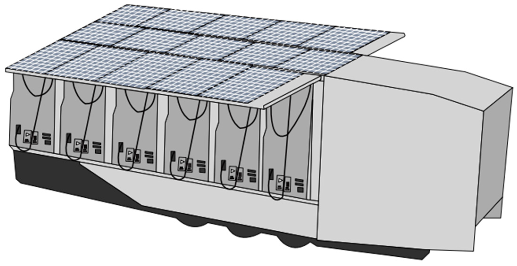
3.6. Feasibility of Solar Canopy

A typical semi-trailer has four blank sides that are typically used for advertisement of the store or company for which the trailer is hauling goods. This project would make use of these to protect the chargers while in transport and shade vehicles while they are charging. However, since these canopies are moveable, it would make them ideal canvases for photovoltaic (PV) panels. Photovoltaics (PVs) are widely adopted forms of renewable energy [36] and incorporating solar canopies into the design allows for dual functionality, providing shade while also generating clean electricity.
Current off-the-shelf PV panels have an efficiency of 25%, with emerging technologies currently being researched approaching 46% [37]. The average direct irradiation on Earth each day varies based on a location’s distance from the equator, but for the United States, it can vary from 3.5 to 6.5 kWh/m2 per day [38]. For the purposes of this study, the average for Logan, Utah was used, which is around 5 kWh/m2 per day. Given the coverable surface area of the trailer is 132.4 m2, the estimated output from the panels would be 165 kWh/day given the following equation:
C PV = DI   ×   SA   ×   η PV ,
Here, the generating capacity of the PV system in kWh (CPV) is estimated using the direct irradiation in kWh/m2 (DI) for the deployment location, the surface area (SA) of the trailer in m2, and the efficiency of the PV panels ( η P V ). This would increase the available energy by an additional 4.7 estimated charges per day, or a 10% increase in capacity, given the currently available technology. Any PV system comes at a cost in both tangible dollars and the complexity of the system. With an estimated system size of 33 kW, given the estimate of $1.70 per watt provided by the National Renewable Energy Laboratory (NREL), we can estimate the total system cost of $56,000 [39]. It would also require the installation of a solar charge controller and an additional DC-to-DC converter to boost the voltage to charge the battery.

3.7. Integrated Design

As previously discussed, the limiting factor for this study was the maximum weight of the trailer. The safety of lithium iron phosphate (LFP) batteries comes at the cost of a lower energy density compared to nickel manganese cobalt (NMC) chemistry cells. This study deemed it a worthy trade-off, but the battery calculation did not take into account other sources of weight.
The charging equipment and DC-to-DC conversion equipment would be the next greatest source of weight. The only currently known converter capable of the power input and output required for this design was created by Volkswagen Group for use in the Porsche Taycan and Audi e-Tron lines of vehicles [40]. This converter was specifically meant to allow the vehicles to charge at 150 kW when using 400 V DC fast-charging stations compared to the typical 50 kW the vehicles would be limited to at such a station. Because this device is proprietary, its exact weight and dimensions are not known. Other converters capable of taking in similar power ratings but outputting a significantly lower voltage are common and weigh 9 kg (20 lbs) [41].
Most of the weight and size of DC fast chargers come from their switching equipment, rectifying AC voltage from the grid to DC voltage that can be accepted by the battery. Since that is all able to be replaced with the DC-to-DC converter, only the charge cable and user interface components such as an LCD remain. A typical CCS Type-1 cable comes in at 7.5 kg (16.5 lbs) with the rest being negligible [42].
The final major source of weight is expected to be the solar canopy, incorporated into the design highlighted in Figure 2. Estimates show that the weight of typical residential panels is about 11 kg/m2 (24.3 lbs/m2) [43]. That brings the total solar installation to 1456 kg (3210 lbs), which provides approximately 165 kWh of energy per day, based on data detailed in Section 3.6. To add the solar canopy, the battery would have to be decreased in size by 234 kWh. Due to the unpredictability of the amount of solar energy generated per day due to clouds, time of year, and other factors, it would not be advantageous to add solar at this time given the current technology. Therefore, our final design for this study does not include a solar canopy. Figure 2 shows the proposed design for a charging trailer with six stalls and a solar canopy.

4. Cost Analysis and Feasibility

Most of the parts for a trailer like the one discussed can be bought off the shelf with the sole exception of the DC-to-DC converter. Batteries and solar panels, if equipped, are readily available for purchase. To determine the number of battery cells that are required to meet a specific cube voltage, the following equation should be used:
  C S = V D V C ,  
Here, the number of cells needed in series ( C s ) is calculated by dividing the desired voltage ( V D ) by the voltage of an individual cell ( V c ). Thus, each Power Cube would need 125 3.2 V LFP cells wired in series for a nominal voltage of exactly 400 V. For cubes installed in a trailer without solar, the total weight would be limited to 3780 kg per cube to meet the restraints discussed in Section 3.2. This would allow for approximately 10.25 blocks wired in parallel, calculated using:
C B = W C W C × C S ,
The number of cell blocks (CBs) is calculated using the maximum weight of each cube (WC), the weight of a single cell (WC), and the number of cells needed in series (CS). With the current technology, each block would contain 150 Ah for a total energy capacity of 615 kWh per cube. Given the price of $83 per battery, the cost of the battery for each cube is estimated to be $106,000 [44,45,46]. For six total cubes per trailer, the cost of the batteries is estimated to reach $636,000. For this design of the trailer, the battery would be the only major known cost source. The estimated cost for a standard trailer is $40,000, with a refrigerated trailer estimated to be $60,000. Since the CCS cables used for the trailer can be standard, off-the-shelf units, the price is estimated to be $5500 per cable, bringing the total for CCS cabling up to $33,000. Hence, the minimum total cost without solar is $729,000, and with solar is $785,000. Custom work would need to be carried out to build the cubes and the rail mounting system and make use of the refrigerated trailer’s HVAC system to cool and heat the battery coolant through the custom backplane.
If a user were to add the solar canopy, the total capacity of the trailer would decrease by 234 kWh, reducing the cost of the batteries by $40,000. However, as discussed in 3.5, the solar comes at a cost of $56,000. Either option would cost a minimum of $730,000 before custom fabrication. Given that Electrify America (EA) charges an average of $0.56 per kWh, barring any other expense such as the equipment and electricity to charge the trailer, the trailer would need to dispense 1.25 GWh of energy before it would break even given the current cost of batteries [28]. This would take two consecutive years of usage per the usage rates calculated in Section 3.3.
When compared to the cost of a grid-connected DCFC, the feasibility of a trailer like the one discussed begins to make more sense. In their attempt to plug charging holes in their most important travel corridors, the State of California found that an off-grid, self-supporting DCFC station could cost as much as $858,000. For rural sites that were able to be connected to the grid, the cost was lower but nevertheless considerable: $122,000 to $440,000 per station [47]. In these rural situations where the chargers may never be at full capacity and take years or longer to generate profit, it might make sense for charge point operators (CPOs) to go with a mobile approach such as the one outlined in this paper.
Alongside the design costs, it is crucial to consider the transportation costs associated with deploying MCS. These costs primarily encompass the fuel expenses required for the MCS to travel from its origin to the designated charging destinations, as well as driver compensation, maintenance, and insurance. Among these costs, fuel expenses and driver compensation contribute more than others. Given that our design involves a semi-truck, operating expenses in trucking are estimated to be between $1.16 and $3.05 per mile [48]. The fuel cost, FC, of a semi-truck can be calculated as:
FC = ( D / F Eff )   × F p ,
where D is the total travel distance back and forth from the MCS’s starting location to the charging destination, F C is the fuel cost, F E f f is fuel efficiency—the number of miles the truck can travel per gallon of fuel—and F p is the fuel price—the cost of one gallon of fuel [49].
The study also analyzed the per kWh cost of MCS. Understanding these costs is crucial for evaluating the financial feasibility and sustainability of deploying MCS units. Equation (8) represents the cost per kWh, and CPK can be calculated by dividing the total cost by the total energy dispensed over the life of the charger. We calculated the cost for both with solar canopy and without solar canopy and obtained $0.5832 per kWh and $0.628 per kWh, respectively.
CPK = Total   Cos t Total   Energy   Dispensed ,
Without   solar   canopy :   CPK = $ 729 , 000 1 , 250 , 000   kWh = $ 0.5832   per   kWh
With   solar   canopy :   CPK = $ 785 , 000 1 , 250 , 000   kWh = $ 0.628   per   kWh
However, public DCFCs encounter significantly different prices depending on where they plug in. The study by Bernal et al. [50] evaluated the economic viability of fast-charging stations in the U.S. The charging prices tend to vary between $0.22 per kWh and $0.56 per kWh [51]. The cost analysis reveals that the expense per kWh for a grid-connected charging station or DCFC averages around $0.22 per kWh to $0.56 per kWh, whereas the Mobile Charging Station (MCS) operates at approximately $0.5832 per kWh. Although the unit cost for the MCS is higher compared to DCFC fixed charging stations, the additional expenditure can be justified by the significant advantages the MCS offers. The flexibility of the MCS allows for rapid deployment in areas experiencing temporary surges in demand or where fixed infrastructure is not feasible. Furthermore, in emergencies or during extended power outages, the MCS proves invaluable, ensuring continuity of service when traditional stations might be compromised. Additionally, the MCS can be strategically positioned during peak usage times or in high-demand areas, effectively reducing congestion and wait times at permanent sites. This combination of mobility, versatility, and on-demand deployment makes the MCS an essential component of a comprehensive EV charging infrastructure, despite its higher per-unit cost.
Table 2 outlines the finalized cost parameters for the design of the self-contained, mobile electric vehicle charging station.

5. Discussion

The design and feasibility analysis of the mobile, self-contained charging station reveal several insights that highlight differences from conventional fixed charging infrastructure. The modular trailer-based system, featuring a ‘Power Cube’ concept, indicates that rapid deployment and operational flexibility can be achieved without sacrificing technical performance. The use of LFP batteries, despite their lower energy density compared to NMC cells, offers advantages in terms of safety and thermal stability, which is critical when integrating a large energy storage system into a mobile platform.
The detailed cost analysis shows that the MCS operates at a higher cost (approximately $0.583 per kWh without solar and $0.628 per kWh with solar) compared to some grid-connected fixed charging stations. However, the benefits of mobility, such as the ability to serve ‘charging deserts’ and areas with temporary surges in demand, such as during emergencies or peak travel periods, may compensate for these higher costs. This flexibility can alleviate congestion at permanent sites and provide CPOs with the opportunity to evaluate new locations without committing to fixed installations.
Moreover, the design’s optional integration of a solar canopy could enhance the environmental sustainability of the MCS by reducing its reliance on fossil fuel-based grid power and contributing to grid resilience. Although incorporating solar panels necessitates a slight reduction in battery capacity, the dual charging strategy (using both solar and grid electricity) could support the station’s sustainability and operational resilience, particularly in remote or off-grid scenarios.
The system’s scalability and the potential for future upgrades, such as implementing an 800 V compatible design, could decrease charging times and expand its applicability to include commercial fleets. Nevertheless, challenges such as optimizing the energy management strategy, mitigating battery degradation under extreme environmental conditions, and enhancing the integration of smart grid technologies remain. These challenges highlight the necessity for ongoing research to ensure that the potential benefits of mobile charging can be effectively realized in practical settings.

6. Conclusions and Future Research

This paper outlined and discussed the design of a novel EV DC fast charger integrated into the trailer of a semi-truck. By leveraging modular “Power Cube” units and a robust cost framework, the proposed MCS addresses several limitations of fixed charging infrastructure, notably, limited accessibility, inflexible deployment, and the challenges of emergency response. The selection of LFP cells, based on safety considerations despite their lower energy density, indicates a cautious approach to materials selection. As battery technologies evolve, future updates could potentially increase energy density or reduce costs. Although the MCS shows a higher operational cost per kWh than traditional grid-connected stations, its operational flexibility could offer a valuable solution for regions with infrastructure gaps. Future research might explore the integration of more efficient solar technologies to further improve the environmental impact of the MCS and increase its energy independence. In addition, field studies to evaluate the performance, reliability, and user acceptance of the MCS in various operational scenarios would provide valuable insights.

Author Contributions

Conceptualization, R.S. and H.W.; methodology, R.S., A.S., D.K. and H.W.; formal analysis, R.S. and A.S.; investigation, R.S., A.S., D.K. and H.W.; data curation, R.S.; writing—original draft preparation, R.S. and H.W.; writing—review and editing, A.S. and H.W.; visualization, A.S. and D.K.; supervision, H.W.; project administration, H.W.; funding acquisition, H.W. All authors have read and agreed to the published version of the manuscript.

Funding

This research was funded by US National Science Foundation grant number EEC-1941524 and the APC was funded by the same grant.

Institutional Review Board Statement

Not applicable.

Informed Consent Statement

Not applicable.

Data Availability Statement

Data are contained within the artcle.

Conflicts of Interest

The authors declare no conflict of interest.

References

  1. Li, H.; Son, D.; Jeong, B. Electric vehicle charging scheduling with mobile charging stations. J. Clean. Prod. 2024, 434, 140162. [Google Scholar] [CrossRef]
  2. Sultana, A.; Ma, X.; Hu, R.Q.; Wang, H. Power Scheduling and Cost Optimization of a Grid Integrated PV and BESS Fast Charging using SARSA Reinforcement Learning. In Proceedings of the 2024 IEEE 100th Vehicular Technology Conference (VTC2024-Fall), Washington DC, USA, 7–10 October 2024; IEEE: Piscataway, NJ, USA, 2024; pp. 1–6. [Google Scholar]
  3. Flores, R.J.; Shaffer, B.P.; Brouwer, J. Electricity costs for an electric vehicle fueling station with Level 3 charging. Appl. Energy 2016, 169, 813–830. [Google Scholar] [CrossRef]
  4. Chakravarthy, B.K.; Lakshmi, G.S.; Bhupathi, H.P. Review on charging methods and charging solutions for electric vehicles. In Proceedings of the E3S Web of Conferences, Kavala, Greece, 19–21 June 2024; EDP Sciences: Les Ulis, France, 2024; Volume 547, p. 03001. [Google Scholar]
  5. Motoaki, Y. Location-allocation of electric vehicle fast chargers—Research and practice. World Electr. Veh. J. 2019, 10, 12. [Google Scholar] [CrossRef]
  6. Amariei, F. Tesla’s Largest Supercharger Station is Open, Has Solar Canopies and Pull-Through Spots. Autoevolution, 5 September 2023. [Google Scholar]
  7. PlugShare. Terrible Herbst. Quartzsite, AZ. EV Station. Available online: https://www.plugshare.com/location/545099 (accessed on 13 March 2025).
  8. Afshar, S.; Macedo, P.; Mohamed, F.; Disfani, V. Mobile charging stations for electric vehicles—A review. Renew. Sustain. Energy Rev. 2021, 152, 111654. [Google Scholar] [CrossRef]
  9. Pevec, D.; Babic, J.; Carvalho, A.; Ghiassi-Farrokhfal, Y.; Ketter, W.; Podobnik, V. Electric vehicle range anxiety: An obstacle for the personal transportation (r) evolution? In Proceedings of the 2019 4th International Conference on Smart and Sustainable Technologies (Splitech), Split, Croatia, 18–21 June 2019; IEEE: Piscataway, NJ, USA, 2019; pp. 1–8. [Google Scholar]
  10. Afshar, S.; Macedo, P.; Mohamed, F.; Disfani, V. A literature review on mobile charging station technology for electric vehicles. In Proceedings of the 2020 IEEE Transportation Electrification Conference & Expo (ITEC), Chicago, IL, USA, 23–26 June 2020; IEEE: Piscataway, NJ, USA; pp. 1184–1190. [Google Scholar]
  11. Veneri, O.; Ferraro, L.; Capasso, C.; Iannuzzi, D. Charging infrastructures for EV: Overview of technologies and issues. In Proceedings of the 2012 Electrical Systems for Aircraft, Railway and Ship Propulsion, Bologna, Italy, 16–18 October 2012; pp. 1–6. [Google Scholar]
  12. Atmaja, T.D.; Mirdanies, M. Electric vehicle mobile charging station dispatch algorithm. Energy Procedia 2015, 68, 326–335. [Google Scholar] [CrossRef]
  13. Asensio, O.I.; Alvarez, K.; Dror, A.; Wenzel, E.; Hollauer, C.; Ha, S. Real-time data from mobile platforms to evaluate sustainable transportation infrastructure. Nat. Sustain. 2020, 3, 463–471. [Google Scholar] [CrossRef]
  14. Rempel, D.; Cullen, C.; Matteson Bryan, M.; Vianna Cezar, G. Reliability of open public electric vehicle direct current fast chargers. Hum. Factors 2024, 66, 2528–2538. [Google Scholar] [CrossRef] [PubMed]
  15. Afshar, S.; Pecenak, Z.K.; Barati, M.; Disfani, V. Mobile charging stations for EV charging management in urban areas: A case study in Chattanooga. Appl. Energy 2022, 325, 119901. [Google Scholar] [CrossRef]
  16. Huang, S.; He, L.; Gu, Y.; Wood, K.; Benjaafar, S. Design of a mobile charging service for electric vehicles in an urban environment. IEEE Trans. Intell. Transp. Syst. 2014, 16, 787–798. [Google Scholar] [CrossRef]
  17. Desai, J.; Mathew, J.K.; Sturdevant, N.J.; Bullock, D.M. Longitudinal monitoring of electric vehicle travel trends using connected vehicle data. World Electr. Veh. J. 2024, 15, 560. [Google Scholar] [CrossRef]
  18. Desai, J.; Mathew, J.K.; Li, H. Using connected vehicle data for assessing electric vehicle charging infrastructure usage and investment opportunities. Institute of Transportation Engineers. ITE J. 2022, 3, 22–31. [Google Scholar]
  19. PlugShare. Smith’s Kingman AZ. Kingman, AZ. EV Station. Available online: https://www.plugshare.com/location/315440 (accessed on 13 March 2025).
  20. Millerandzois. Weight and Size of Tractor Trailers. 6 November 2024. Available online: https://www.millerandzois.com/practice-areas/maryland-truck-accident-lawyer/maryland-truck-accident-law/weight-tractor-trailer/ (accessed on 13 March 2025).
  21. Mikheenkova, A.; Smith, A.J.; Frenander, K.B.; Tesfamhret, Y.; Chowdhury, N.R.; Tai, C.W.; Thiringer, T.; Lindström, R.W.; Hahlin, M.; Lacey, M.J. Ageing of high energy density automotive li-ion batteries: The effect of temperature and state-of-charge. J. Electrochem. Soc. 2023, 170, 080503. [Google Scholar] [CrossRef]
  22. Nájera, J.; Arribas, J.R.; De Castro, R.M.; Núñez, C.S. Semi-empirical ageing model for LFP and NMC Li-ion battery chemistries. J. Energy Storage 2023, 72, 108016. [Google Scholar] [CrossRef]
  23. Ohneseit, S.; Finster, P.; Floras, C.; Lubenau, N.; Uhlmann, N.; Seifert, H.J.; Ziebert, C. Thermal and mechanical safety assessment of type 21700 lithium-ion batteries with NMC, NCA and LFP cathodes–Investigation of cell abuse by means of accelerating rate calorimetry (ARC). Batteries 2023, 9, 237. [Google Scholar] [CrossRef]
  24. Brand, M.; Gläser, S.; Geder, J.; Menacher, S.; Obpacher, S.; Jossen, A.; Quinger, D. Electrical safety of commercial Li-ion cells based on NMC and NCA technology compared to LFP technology. In Proceedings of the 2013 World Electric Vehicle Symposium and Exhibition (EVS27), Barcelona, Spain, 17–20 November 2013; IEEE: Piscataway, NJ, USA, 2013; pp. 1–9. [Google Scholar]
  25. Schöberl, J.; Ank, M.; Schreiber, M.; Wassiliadis, N.; Lienkamp, M. Thermal runaway propagation in automotive lithium-ion batteries with NMC-811 and LFP cathodes: Safety requirements and impact on system integration. Etransportation 2024, 19, 100305. [Google Scholar] [CrossRef]
  26. Electrify America. 2023 Annual Report to the Environmental Protection Agency. Electrify America Media. Available online: https://media.electrifyamerica.com/assets/documents/original/1157-2023EPAAnnualReportFinal43024Public.pdf (accessed on 13 March 2025).
  27. Backhaus, R. Cell Development for the Batteries of Future Electric Vehicles. ATZ Worldw. 2023, 125, 10–15. [Google Scholar]
  28. Sanchez, E.A. Charger Beware: The Byzantine, Inconsistent Terms of EV Charging. The Watt Car, 30 May 2024. [Google Scholar]
  29. Kane, M. Hyundai’s E-GMP Can Use 400/800V DC Chargers but What is the Efficiency? InsideEVs, 2 December 2020. [Google Scholar]
  30. Safayatullah, M.; Elrais, M.T.; Ghosh, S.; Rezaii, R.; Batarseh, I. A comprehensive review of power converter topologies and control methods for electric vehicle fast charging applications. IEEE Access 2022, 10, 40753–40793. [Google Scholar] [CrossRef]
  31. Kurowicki, J. 2024 Chevy Silverado EV is the New Champ of Our Fast-Charging Test, Second in Range. Car and Driver, 21 June 2024. [Google Scholar]
  32. Holderith, P. Here’s an Exceedingly Nerdy Explanation of GM’s Ultium Battery System. Motor1, 26 April 2024. [Google Scholar]
  33. Dow, J.; Dow, J. First seen Cybertruck charging curve disappoints, but is that the whole story? Electrek, 31 December 2023. [Google Scholar]
  34. Delta Electronics (Netherlands) BV. DC Charger/UFC 500; Delta Electronics: Hoofddorp, The Netherlands, 2024. [Google Scholar]
  35. Wevo Energy. North American Charging Standard: Technical Specification. Available online: https://wevo.energy/glossary/nacs/ (accessed on 13 March 2025).
  36. Amin, A.; Sultana, A.; Hasan, J.; Islam, M.T.; Khan, F. Solar home system in Bangladesh: Prospects, challenges and constraints. In Proceedings of the 2014 3rd International Conference on the Developments in Renewable Energy Technology (ICDRET); Dhaka, Bangladesh, 29–31 May 2014, IEEE: Piscataway, NJ, USA, 2024; pp. 1–5. [Google Scholar]
  37. Dhilipan, J.; Vijayalakshmi, N.; Shanmugam, D.B.; Ganesh, R.J.; Kodeeswaran, S.; Muralidharan, S. Performance and efficiency of different types of solar cell material—A review. Mater. Today Proc. 2022, 66, 1295–1302. [Google Scholar] [CrossRef]
  38. National Renewable Energy Laboratory. Global Horizontal Solar Irradiance; NREL: Golden, CO, USA, 2018. [Google Scholar]
  39. Ramasamy, V.; Zuboy, J.; O’Shaughnessy, E.; Feldman, D.; Desai, J.; Woodhouse, M.; Basore, P.; Margolis, R. Us Solar Photovoltaic System and Energy Storage Cost Benchmarks, with Minimum Sustainable Price Analysis: Q1 2022 (No. NREL/TP-7A40-83586); National Renewable Energy Lab. (NREL): Golden, CO, USA, 2022. [Google Scholar]
  40. Range and Charging. Porsche Newsroom. Audi e-Tron GT Dc Converter; Transform-9J1959663BG. Audi Genuine Parts. Available online: https://parts.audiusa.com/p/Audi__e-tron-GT/DC-CONVERTER-TRANSFORM/109142843/9J1959663BG.html (accessed on 13 March 2025).
  41. VTC1550-12 VTC1550 DC/DC Converter 100-400VDC to 12VDC 100A. MDS Power. Available online: https://www.mdspower.com/vtc1550-dc-dc-converter-100-400vdc-to-12vdc-110a-vtc1550-12?srsltid=AfmBOoqGoGiQxR-g2QqMPylYl5yLrwvq85Vl2aG0-altQAPoMGS8XNUS (accessed on 13 March 2025).
  42. Home. Phoenix Contact. Phoenix Contact USA. Available online: https://www.phoenixcontact.com/en-pc/ (accessed on 13 March 2025).
  43. Idrissi, Y.A.E. How Much Do Solar Panels Weigh? A Complete Guide to Solar Panels Weight. Renewablewise, 24 January 2024. [Google Scholar]
  44. Battery Finds. LiFEPO4 Cells 3.2V. Available online: https://batteryfinds.com/product-category/battery-cells/lifepo4-battery-cells-3-2-v/ (accessed on 13 March 2025).
  45. Norstar Truckbeds & Iron Bull Trailers. How Much Does a Truck Trailer Cost? Available online: https://norstarcompany.com/blog/how-much-does-a-truck-trailer-cost/ (accessed on 13 March 2025).
  46. Mouser. 500A Liquid-Cooled Charging Cables. Phoenix Contact. Available online: https://eu.mouser.com/new/phoenix-contact/phoenix-contact-500a-liquid-cooled-charging-cables/?srsltid=AfmBOorcgtB1KuxbphlrRoETS1zK0jisZkOf3pDJigWxPsY05SX3c2-1 (accessed on 13 March 2025).
  47. Gamage, T.; Tal, G.; Jenn, A.T. The costs and challenges of installing corridor DC Fast Chargers in California. Case Stud. Transp. Policy 2023, 11, 100969. [Google Scholar] [CrossRef]
  48. Henry, C. What is Total Cost Per Mile for Truckload Carriers? FreightWaves, 14 January 2020. [Google Scholar]
  49. Fleetworthy. Fuel Cost Calculator for Semi-Trucks & Cars. Drivewyze, 3 February 2025.
  50. Bernal, D.; Raheem, A.A.; Inti, S.; Wang, H. Assessment of Economic Viability of Direct Current Fast Charging Infrastructure Investments for Electric Vehicles in the United States. Sustainability 2024, 16, 6701. [Google Scholar] [CrossRef]
  51. Stable Insights. EV Charging Pricing Trends. StableAuto. Available online: https://stable.auto/insights/electric-vehicle-charger-price-by-state (accessed on 13 March 2025).
Figure 1. The PlugShare map displays available public DCFCs (marked with orange pins) and a black route indicating the charging deserts along Interstate 40 and US Highway 93.
Sustainability 17 02767 g001
Figure 2. The proposed design of a charging trailer with six stalls and a solar canopy.
Sustainability 17 02767 g002
Table 1. Design constraints of the proposed design of self-contained MCS.
Constraint CategoryConstraint DescriptionImpact
Weight LimitationsThe total weight of the mobile charging station must not exceed 36,287 kg (80,000 lbs).Necessary to comply with road transportation regulations and ensure the mobility of the charging station via a standard semi-truck.
Size ConstraintsAll components, including power electronics and batteries, must fit within a semi-trailer.Ensures the unit can be transported together.
Power SupplyThe station must be capable of utilizing a standard electrical grid supply and incorporate renewable sources to energize.Allows for versatility in deployment locations, through grid connection and self-sustained via solar power, enhancing deployment flexibility.
Energy CapacityThe battery system must store enough energy to meet the charging demand until the next recharge.Ensures the station can function effectively during necessity without immediate access to grid power.
Environmental AdaptabilityMust operate reliably under varying climatic conditions.Ensures functionality across diverse environments, crucial for deployments in areas with extreme weather conditions.
Cost EfficiencyThe design and operation costs must align with budget constraints while ensuring economic viability.Balances practical financial limits of the project, aiming for long-term sustainability and profitability of the charging station.
Safety StandardsAdherence to all relevant safety standards and regulations for electrical systems and battery storage.Critical for public safety and regulatory compliance, particularly in handling and storing large amounts of electrical energy.
ModularityDesign must allow for modular assembly and disassembly for maintenance and upgrades.Facilitates easier maintenance, scalability, and future upgrades without requiring complete redesigns.
Charging SpeedCapable of delivering fast charging capabilities comparable to fixed stations (e.g., DC fast charging).Ensures the station’s attractiveness to EV users by minimizing charging time.
User InterfaceMust include user-friendly interfaces and accessibility features.Ensures the charging station is easy to use for a diverse range of customers.
Table 2. Finalized cost parameter of the proposed design of self-contained MCS.
Cost ParameterDetailsCost (USD)
Battery Cost per Cube150 Ah LFP cells per cube, total 6 cubes$106,000 per cube
Total Cost for Batteries6 cubes$636,000
Trailer CostRefrigerated trailer $60,000
Charging CablesCCS cables, total 6$5500 per cable
Total Cost for CCS Cables6 cables$33,000
Solar Canopy InstallationOptional, includes panels, controllers, and converters$56,000
Total Minimum CostExcluding optional solar canopy and unspecified items$729,000
Total Cost with Solar CanopyIncluding solar canopy and all components$785,000
Disclaimer/Publisher’s Note: The statements, opinions and data contained in all publications are solely those of the individual author(s) and contributor(s) and not of MDPI and/or the editor(s). MDPI and/or the editor(s) disclaim responsibility for any injury to people or property resulting from any ideas, methods, instructions or products referred to in the content.

