Abstract
The growing need for clean and efficient energy has led to more interest in hydrogen-based technologies for improving combustion. Oxyhydrogen (HHO) generators have become a possible way to improve fuel efficiency and reduce emissions in engines by adding hydrogen to the air–fuel mix. However, problems like energy loss, uneven hydrogen output, and inefficiency have slowed their use. This study looked at the design, development, and testing of a better HHO generator that solves these issues by adding a better cooling system and adjusting the potassium hydroxide (KOH) mixture (20 g, 25 g, and 30 g). The goal was to see how these changes affect hydrogen production, energy use, and system stability. The results showed that increasing the KOH mixture improved hydrogen production and electrical conductivity. The cooling system helped reduce energy loss and kept the output steady. The improved generator, using 30 g of KOH and the cooling system, produced a peak hydrogen concentration of 31 PPM—more than double that of a regular unit (14 PPM). It also worked with an efficiency of 21.4%, using 25 W of power compared to 30 W for the regular unit, saving 16.7% in energy. These findings show that this improved HHO generator could be a good and efficient solution for cars and renewable energy uses.
1. Introduction
Hydrogen has emerged as a promising alternative to conventional fossil fuels in the quest for sustainable transportation solutions. Implementing HHO generators offers potential improvements in fuel efficiency, emissions reduction, and a transition towards renewable energy sources. HHO generators are mainly used in cars to help save fuel and reduce pollution. They mainly produce hydrogen and oxygen by electrolysis with the presence of an electrolyte, which is added to the fuel. This makes the engine run better and cleaner. HHO generators are also used in factories for cutting and welding, providing a clean and efficient energy source. Their ability to save fuel and reduce emissions makes them valuable in both cars and industrial uses. Beyond technical benefits, the designed generator offers advantages across social, economic, and environmental dimensions. It can lower transportation costs, making travel and deliveries more affordable, especially for companies with large vehicle fleets. By improving fuel efficiency, it helps people and businesses save money, while promoting cleaner combustion to reduce harmful emissions.
Previously conducted studies examine the impact of HHO generators on engine efficiency, emissions reduction, and sustainability. By reviewing key studies, we highlight improvements in thermal efficiency, fuel savings, and emission control. Kumar et al. [1] found that hydrogen induction in a GDI engine improved brake thermal efficiency and lowered hydrocarbon emissions, with an optimal hydrogen mass share of 10%. Similarly, Arjun et al. [2] reported a 10% efficiency boost and 34% fuel savings in petrol engines using HHO gas, with 6 g/L KOH as the most effective catalyst.
Studies by Sharma et al. [3] and Musmar et al. [4] confirmed that HHO gas enhances combustion, reducing NOx emissions and fuel consumption in multi-cylinder engines. Essumanet al. [5] observed higher power output and thermal efficiency with HHO use. Research on HHO production optimization by Jannah and Susilo [6], Colli et al. [7], and Susilo et al. [8] highlighted that brass and stainless-steel electrodes combined with NaHCO₃ catalysts increased gas output. El Soly et al. [9] found that dry cells were more compact and heat-efficient, whereas wet cells produced greater gas volume. Karthik [10] and Al massri et al. [11] highlighted that 316 L stainless steel resists corrosion well, while ammonia hydroxide increases gas output but also corrosion risk. Butt et al. [12] discussed the combination of an HHO generator with solar photovoltaic (PV) systems to create a self-sustaining energy source. The study focused on optimizing the HHO generator’s performance, aiming to operate it independently using solar energy. By integrating solar PV, the system can generate hydrogen and oxygen gases without relying on external power sources, making it a more environmentally friendly and efficient solution.
Kultsum et al. [13] investigated the integration of a commercial HHO generator into a four-stroke, spark-ignition engine to assess its impact on performance metrics such as torque, power, and fuel consumption. By varying the input voltages to the HHO generator (15 V, 25 V, and 30 V), their study evaluated the engine’s response through experimental dynamometer tests and numerical analyses. The findings show that higher input voltages boost HHO production, but engine performance gains are modest, likely due to energy losses during conversion. In a separate study, Kultsum et al. [14] investigated how varying NaOH concentrations (2–10%) and electrode plate numbers (2, 4, 6) affect HHO production and hydrostatic pressure. The results showed that increasing both parameters boosts gas output and pressure. The best performance was achieved using 10% NaOH and six plates, emphasizing the importance of parameter optimization for efficient HHO generation. Mutlag et al. [15] studied a wet-cell HHO generator with stainless-steel plates and a KOH solution, finding that 2.5 g/L KOH gave the best efficiency of 11.72 mL/min/W. They suggested regular checks and careful control to prevent problems like drying and dirt buildup, ensuring steady performance. Vinayak et al. [16] designed a high-efficiency HHO generator, achieving 180 mL/min hydrogen output at 118 W, emphasizing low carbon emissions, cost-effectiveness, and potential for large-scale use. Usmanet al. [17] recommended stainless steel 316 L for HHO generators due to its durability, affordability, and resistance to KOH corrosion while exploring alternatives like titanium and coated electrodes for better efficiency and lower costs.
This study focuses on the design, development, and experimental evaluation of an oxyhydrogen (HHO) generator to enhance vehicle fuel efficiency and reduce harmful emissions. Exhaust emissions were examined as the primary measure to evaluate the impact of HHO gas on engine performance, following established research in the field [18]. These emissions are commonly used in experimental studies to assess methods for improving combustion, ensuring compatibility with previous findings. Testing methods were selected to guarantee accuracy, consistency, and practical application within a controlled laboratory setting. While advanced techniques such as CFD modeling could provide additional insights, the study prioritized experimental validation to directly observe the effects of HHO on combustion behavior. Future research aims to include long-term durability evaluations and investigate the accumulation of deposits. The generator’s performance is analyzed by varying KOH electrolyte concentrations and integrating a cooling system. The findings demonstrate the potential of HHO technology as an energy-efficient and environmentally sustainable solution for applications in automotive systems, industrial processes, and renewable energy integration.
2. Design of the HHO Generator
The design of the HHO generator required the selection of high-quality components and meticulous planning to ensure seamless integration and optimal performance. A 3D modeling software, CATIA V5 R20, was utilized to visualize and refine each component before fabrication. The assembly process was carried out with precision, followed by rigorous testing to validate functionality and performance, highlighting the importance of accuracy and systematic engineering in developing efficient technology. The HHO generator measures 150 × 100 × 80 mm and features two aluminum side bases, each 150 × 100 × 15 mm in size (Figure 1). It includes 4 electrodes—2 anodes and 2 cathodes—each made of stainless steel 316 and measuring 150 × 100 × 1.5 mm (Figure 2). In addition, there are 15 neutral plates, also made of stainless steel 316, with the same dimensions of 150 × 100 × 1.5 mm (Figure 3). This setup ensures efficient hydrogen production and durable construction [19].
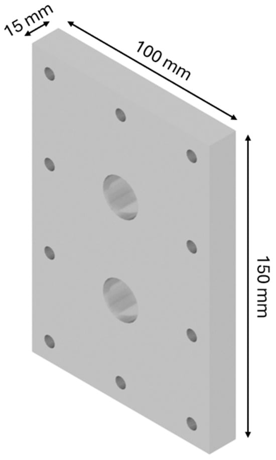
Figure 1.
Designed generator: base.
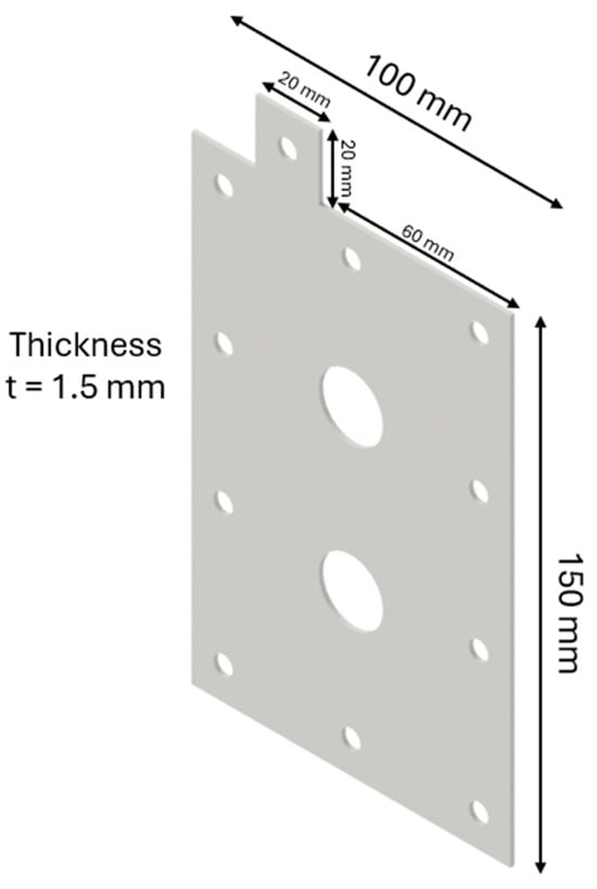
Figure 2.
Designed generator: electrode.
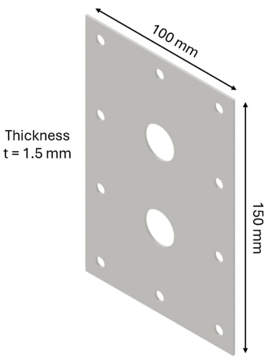
Figure 3.
Designed generator: neutral part.
Figure 4 represents the assembled designed HHO generator, and the exploded view is represented in Figure 5.
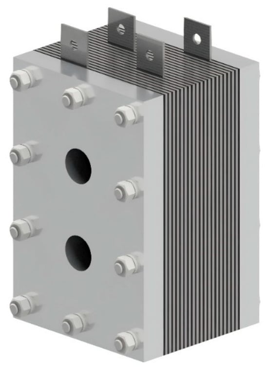
Figure 4.
Designed generator assembled.
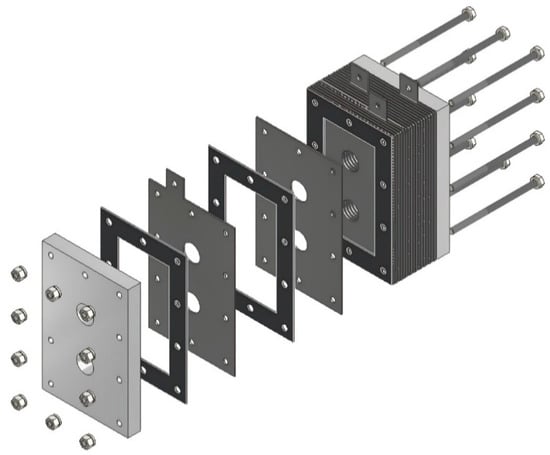
Figure 5.
Designed generator: exploded view.
3. Experimental Setup
This study aims to measure hydrogen flow by adjusting factors like the amount of electrolyte and cooling of the HHO generator. By changing these variables and using accurate flow meters, this study seeks to find the best conditions for producing the most hydrogen. This setup will help to understand how these changes affect hydrogen production efficiency [20].
3.1. Prototype of the Designed HHO Generator
The assembly of the HHO generator was carefully planned to ensure it works efficiently, lasts long, and is easy to maintain (Figure 6). First, the stainless-steel 316 L electrode plates were prepared by laser cutting and polishing to improve conductivity and prevent rusting. These plates were then arranged inside the electrolysis chamber in a specific pattern, with heat-resistant gaskets placed in between to stop short circuits and allow for even gas production. The chamber was made from non-corrosive materials to ensure it remains strong over time, even with continuous electrolysis. Strong fasteners and reinforced seals were used to make sure the chamber was airtight, preventing gas leaks and making the system safe.
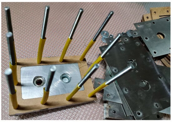
Figure 6.
Assembling the designed parts.
The HHO generator has 3 cells with 4 electrodes and 15 neutral plates, arranged in a +NNNNN–NNNNN+NNNNN– configuration. It uses a 1 L water tank filled with a mixed solution to produce hydrogen and oxygen gas. The generator is connected with 4 mm2 copper wires that can carry up to 30 amps of current. It also has ½ inch water connectors and 12 mm pressure tubes for smooth flow and secure connections. A variable DC generator provides adjustable power, making hydrogen production more efficient and easier to control. The whole setup is held together with ten M6 × 100 mm screws, twenty washers, and ten M6 nuts to keep it stable and strong.
The gas output system includes a bubbler for filtering impurities and preventing backflow, ensuring only clean HHO reaches the engine intake. During the assembly process, multiple tests and calibrations were performed to verify the functionality and reliability of each component.
3.2. Experimental Kit
Experiments were conducted to evaluate hydrogen production efficiency by varying the concentration of KOH (20 g, 25 g, and 30 g) in a 1 L distilled water solution. Figure 7 illustrates the experimental setup, including the apparatus and a flowchart outlining the procedure. Using stainless-steel 316 L electrodes and a KOH electrolyte in distilled water enhances the electrolyzer’s performance. KOH improves conductivity by supplying ions that facilitate efficient charge flow, reducing energy losses. Stainless steel 316 L resists corrosion, ensuring long-term durability and consistent hydrogen production. Distilled water ensures gas purity by avoiding impurities that could hinder reactions. Together, these factors optimize efficiency, stability, and reliability in hydrogen generation.
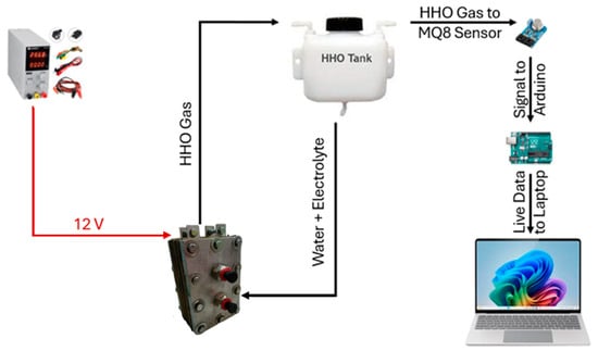
Figure 7.
Flowchart explaining the experimental setup.
The key components of the kit include the following:
- HHO Generator: This is an electrolysis chamber made of non-conductive materials such as acrylic, polypropylene, or PVC. These materials prevent the conduction of electricity outside the chamber, ensuring safety and efficiency. The electrodes, typically made of stainless steel 316, are chosen for their corrosion resistance and durability, which are critical for long-term operation.
- Water Reservoir: Plastic materials such as polyethylene are used, as they are compatible with water and electrolyte solutions.
- Pressure Relief Valve: This is constructed from stainless steel with rubber or silicone seals to regulate pressure and prevent overpressure conditions.
- Electrical Connections: Conductive metals like copper are used to ensure an efficient transfer of electricity to the electrodes.
- Gas Outlet: Corrosion-resistant materials like brass or stainless steel are used to prevent degradation over time.
- Bubblers or Dryers: Non-corrosive materials like PVC are used to remove moisture from the gas.
- Cooling System: Heat sinks made of aluminum are used to dissipate heat and maintain optimal operating temperatures.
The selection of an appropriate power source is crucial for ensuring the efficiency and performance of the system. A stable and consistent electrical supply is required to optimize the electrolysis process, with the choice of power source depending on the specific setup requirements.
Hydrogen concentration is monitored using an MQ-8 hydrogen sensor interfaced with an Arduino microcontroller. To minimize interference, the sensor is enclosed in a plastic casing. A cooling fan is integrated to regulate the system temperature during electrolysis. The process involved dissolving the required amount of KOH in distilled water, filling the 1 L water tank, and running electrolysis for 30 min. Hydrogen levels were measured with and without the fan to assess the impact of cooling on gas production efficiency.
3.3. Experimental Validation
To ensure the accuracy and reliability of the experimental setup (Figure 8), a thorough sensor calibration process was carried out before data collection. The hydrogen concentration was monitored using an MQ-8 Hydrogen Sensor, which required a preheating phase of 10 min to stabilize its readings. The sensor was calibrated against a known hydrogen concentration, 0.25 ppm in a 3 m × 3 m × 3 m room, to ensure precise measurements. Additionally, voltage and current meters were tested with reference instruments to minimize errors in electrical readings. To validate the reproducibility of the experiment, multiple trials were conducted under identical conditions. Each test was repeated several times to assess consistency in hydrogen production, fuel efficiency improvement, and emission reduction. The data collected from each run were analyzed statistically (three trials) to check for variations and ensure repeatability. External factors such as ambient temperature and humidity, recorded at 23 °C and 35%, respectively, were monitored due to their potential impact on electrolysis efficiency. The use of calibrated equipment and controlled conditions ensured reliable and reproducible results, allowing for observed performance improvements to be accurately attributed to the HHO generator.
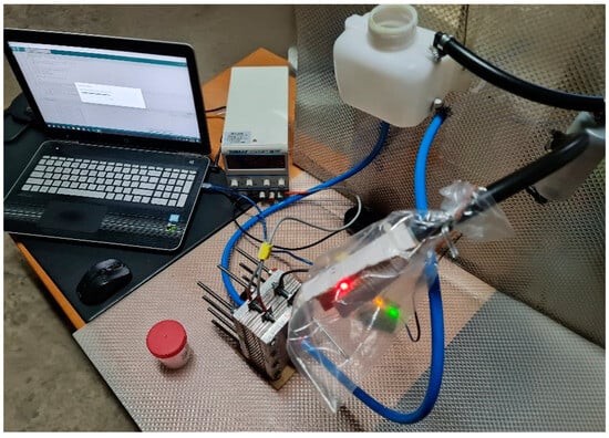
Figure 8.
Experimental setup.
Based on a previous study [21], the acceptable hydrogen mass share for use in an engine is 10% or less. In a 4-cylinder engine running at 1500 RPM, where each cylinder fires once every two revolutions, this results in 750 combustions per cylinder per minute and 3000 total combustions per minute. With a total engine displacement of 2.0 L (0.5 L per cylinder) and an air density of 1.225 g per liter, each cylinder would intake 0.6125 g of air. Given the typical air–fuel ratio of 14.7:1, each combustion requires 0.0417 g of fuel. This leads to a fuel consumption of 125.1 g per minute, with an assumed mass share of 5% of that (6.255 g per minute) needing to come from hydrogen, equivalent to about 70 L per minute. However, generating 70 L/min of hydrogen is impractical with an HHO generator, as the electricity required would exceed the fuel efficiency. Therefore, an external power source is needed to run the system efficiently.
4. Experimental Results
Detailed analysis of the data collected from the experimental setup provides insights into the performance of the HHO generator under various conditions. It was tested with different KOH concentrations, both with cooling applied and without it.
4.1. Hydrogen Production with Varying KOH Concentrations
Three different concentrations of KOH (20 g, 25 g, and 30 g) were tested to evaluate their impact on hydrogen production. The experiments were conducted with and without a cooling fan to assess the significance of temperature control in the efficiency of the HHO generator.
Figure 9 shows the variation in hydrogen concentration over time with 20 g of KOH in the electrolyte solution. The red curve represents the setup with the cooling fan, while the blue curve represents the setup without the cooling fan.
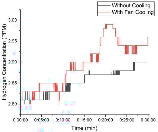
Figure 9.
Variation in hydrogen concentration with time using 20 g of KOH.
At the beginning of the experiment, both setups—one with a cooling fan and one without—generated nearly identical hydrogen concentrations. This indicates that the initial conditions had a minimal influence on hydrogen production. However, as the experiment continued, temperature differences became more pronounced, affecting gas output. The setup with the cooling fan maintained a lower temperature, leading to a more stable and higher hydrogen concentration. The hydrogen concentration in the fan-cooled setup peaked at 2.99 PPM, whereas the non-cooled setup reached a slightly lower maximum of 2.9 PPM. This suggests that cooling enhances efficiency by preventing overheating, which can positively impact hydrogen production over time. As the experiment progressed, the difference in hydrogen concentration between the cooled and non-cooled setups became more pronounced, indicating that the impact of cooling on gas stability and efficiency increased over time with 20 g of KOH.
Figure 10 illustrates the hydrogen concentration with 25 g of KOH. The cooling fan setup consistently produced higher hydrogen concentrations, peaking at 3.78 PPM, while the setup without the fan reached 3.75 PPM.
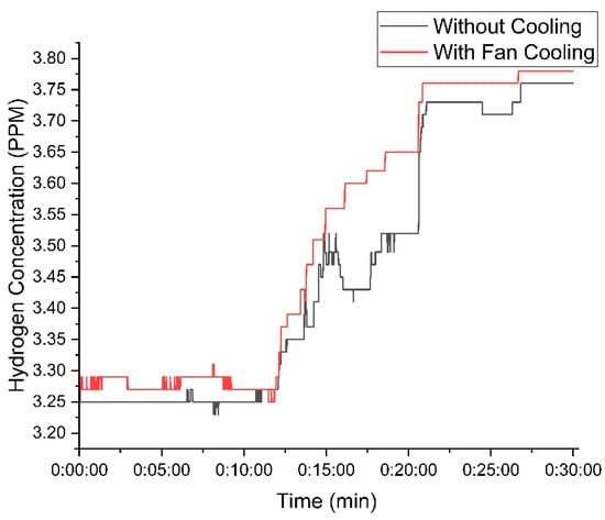
Figure 10.
Variation in hydrogen concentration with time using 25 g of KOH.
The temperature control provided by the cooling fan resulted in more efficient hydrogen production, reducing fluctuations observed in the setup without the fan.
Figure 11 represents the hydrogen concentration using 30 g of KOH. The cooling fan setup achieved a peak concentration of 14 PPM, whereas the setup without the fan reached 13 PPM.
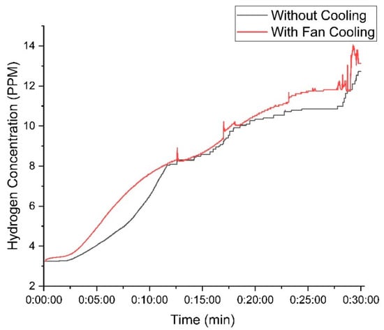
Figure 11.
Variation in hydrogen concentration with time using 30 g of KOH.
When a high mass of KOH is used in the electrolyte solution, the difference in hydrogen production between the cooled and non-cooled setups remains relatively small. This is because higher KOH concentrations enhance the electrolyte’s conductivity, reducing the electrical resistance and naturally increasing hydrogen production in both cases. However, cooling plays a crucial role in stabilizing the system by preventing excessive temperature rise, which can negatively impact electrolysis efficiency. Without cooling, higher temperatures increase water evaporation and introduce fluctuations in current flow, leading to slight inefficiencies. In contrast, the cooling system helps maintain optimal operating conditions, ensuring a more consistent electrolysis process. As a result, the system with cooling not only sustains stable hydrogen output but also improves electrical power efficiency by reducing energy losses associated with overheating and resistance variations, as presented in Table 1.

Table 1.
Electric current with varying KOH concentrations.
Reducing electric power consumption enhances system efficiency, lowers operational costs, extends equipment lifespan, improves stability, and minimizes environmental impact. This contributes to more sustainable and cost-effective hydrogen production.
4.2. Hydrogen Production Using the Designed Generator
In this experiment, the impact of cooling on the performance of an HHO generator is investigated by conducting two tests: one without a cooling system and another using a heat sink and a fan. The electrolyte consisted of 30 g of potassium hydroxide (KOH) dissolved in distilled water. KOH was selected for its high ionic conductivity, which reduces solution resistance and enhances electrolysis efficiency. The electrolysis reaction follows the fundamental decomposition of water 2H2O→2H2 + O2. The current passing through the electrolyte drives this reaction, generating hydrogen and oxygen gases. However, during prolonged operation, the system’s temperature rises due to Joule heating (resistive heating), which impacts overall efficiency.
During the first test (without cooling), the generator experienced thermal accumulation, leading to elevated electrolyte temperatures. As the temperature increased, so did the electrolyte’s evaporation rate, concentrating the KOH solution and altering conductivity. Initially, a moderate temperature increase reduces electrolyte resistance, improving current flow. However, as temperatures rose further, excessive heating led to accelerated water loss and the formation of vapor bubbles on the electrode surfaces, reducing the effective surface area for electrolysis (a phenomenon known as bubble shielding). These effects destabilized the current, causing fluctuations in hydrogen production and an overall decline in system efficiency.
In the second test, the addition of a heat sink and fan significantly improved performance by mitigating thermal buildup. The heat sink, made of thermally conductive material (such as aluminum or copper), dissipated excess heat through conduction, while the fan enhanced convective heat transfer, maintaining a lower and more stable operating temperature. As a result, the electrolyte remained within an optimal temperature range, preventing excessive water evaporation and minimizing bubble formation on electrode surfaces.
The thermal regulation stabilized the electrochemical environment, preserving consistent ionic mobility and preventing voltage instability. Consequently, the system operated with improved electrical conductivity, reduced resistive losses, and sustained a higher electrolysis rate. Hydrogen production doubled compared to the non-cooled setup, as cooling minimized energy loss as heat and maintained a more stable reaction environment.
In the sealed HHO generator, ambient temperature has a minimal effect on performance, whereas internal temperature is a key factor [22]. Elevated internal temperatures enhance ion mobility and overall efficiency; however, if left unchecked, they can cause overheating, increased energy losses, or damage to internal components. Conversely, lower internal temperatures slow reaction rates, reducing efficiency. To address this, we implemented a cooling system to regulate internal conditions, ensuring stable and reliable operation regardless of external environmental variations.
The key improvements observed with cooling are as follows:
- Lower Operating Temperature: The heat sink and fan prevented excessive heating, keeping the electrolyte and electrodes at optimal conditions for electrolysis (typically around 25–35 °C).
- Stable Electrical Power: Reduced temperature fluctuations prevented current drift, ensuring steady voltage and current flow, which is crucial for maintaining a constant electrolysis rate.
- Higher Hydrogen Production: By mitigating bubble shielding and stabilizing reaction conditions, the cooled setup nearly doubled its hydrogen output, achieving peak concentrations of 31 PPM, compared to 14 PPM in the non-cooled system.
- Reduced Energy Losses: Less heat buildup meant more electrical energy was converted into chemical energy (hydrogen production) rather than being wasted as thermal dissipation, increasing the system’s overall Faraday efficiency.
Figure 12 illustrates these improvements, clearly showing how effective thermal management directly enhances hydrogen production and system efficiency. This highlights the importance of integrating cooling mechanisms into HHO generators to maximize their potential as viable, sustainable energy solutions.
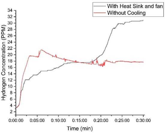
Figure 12.
Variation in hydrogen concentration of the designed generator with time using 30 g of KOH.
4.3. Comparison Between Commercial and Designed Generators
A comparative experiment was conducted to evaluate the performance of the newly designed HHO generator (Figure 13) against a commercial generator (DC2000 HHO Generator) (Figure 14) under identical conditions with 30 g of KOH.
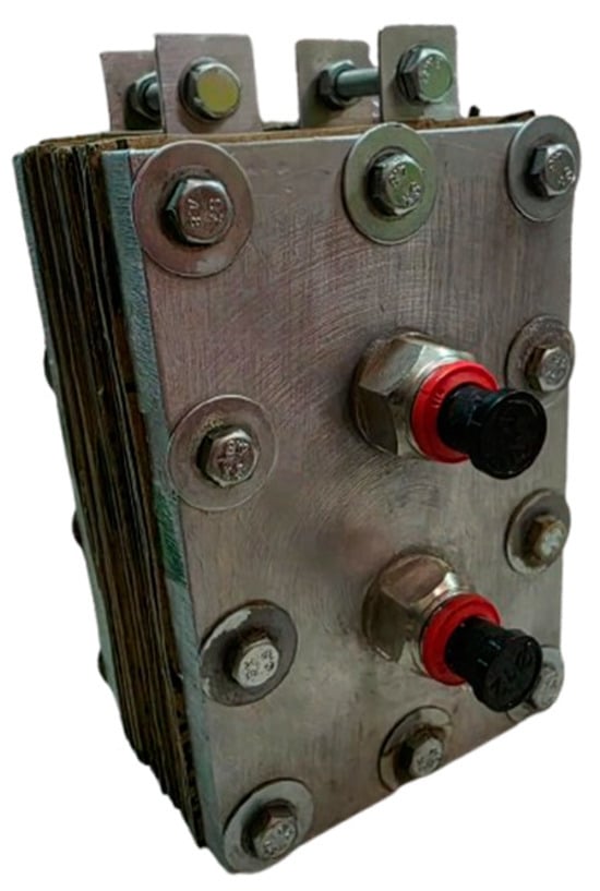
Figure 13.
The final assembly of the designed generator.
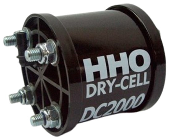
Figure 14.
Commercial DC2000 HHO generator.
Figure 15 compares the hydrogen concentration produced by the DC2000 generator and the new (designed) generator. The new generator significantly outperformed the old one, achieving an average concentration of 20 PPM and a peak of 31 PPM, while the old generator averaged 9 PPM and peaked at 14 PPM. The new generator demonstrated superior efficiency and higher hydrogen production, requiring less power (25 W) compared to the old generator (30 W).
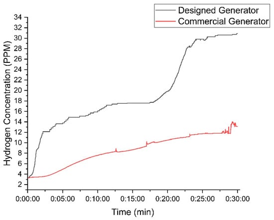
Figure 15.
Comparison between the designed and DC2000 HHO generators while using 30 g of KOH.
The experiments highlighted the importance of maintaining optimal temperature control using a cooling fan, which significantly enhanced hydrogen production efficiency. Additionally, higher KOH concentrations enhanced hydrogen output but required careful management to avoid overheating and efficiency loss. Several generator settings were selected based on previous studies [18,19,20] for comparison with a commercial model. The newly designed generator demonstrated substantial improvements over the commercial one, offering higher hydrogen output with lower power consumption (Table 2).
Table 2.
Electrolysis process summary.
5. Conclusions
This study highlights the significant advancements achieved through the design, development, and experimental evaluation of an optimized oxyhydrogen (HHO) generator. By systematically varying potassium hydroxide (KOH) concentrations and integrating a robust cooling system, the generator demonstrated enhanced fuel efficiency and reduced emissions, solidifying its potential as a sustainable energy solution.
The experimental results underscore the following key insights:
Electrolyte Optimization: Increasing KOH concentrations improved hydrogen production by enhancing electrolyte conductivity, with the 30 g KOH solution yielding the highest hydrogen concentration of 31 PPM—more than double the performance of a commercial unit.
Cooling System Integration: The advanced cooling mechanism stabilized electrolysis by mitigating overheating effects, ensuring consistent hydrogen output, reducing energy losses, and enabling a more reliable electrochemical process.
Efficiency Gains: The optimized generator operated with an efficiency of 21.4%, requiring only 25 W of power, compared to 30 W for its commercial counterpart. This reflects a 16.7% reduction in energy consumption while maintaining superior hydrogen output.
These findings not only highlight the technical benefits of the optimized HHO generator but also emphasize its potential for impactful applications in automotive and renewable energy sectors. The integration of efficient cooling systems represents a pivotal innovation, ensuring operational stability and scalability for widespread adoption.
Looking ahead, further research could focus on the following areas:
Exploring alternative electrode materials to improve corrosion resistance and conductivity.
Investigating different electrolytes to further enhance efficiency and gas output.
Evaluating the integration of HHO generators with hybrid and electric vehicle systems to complement existing sustainable energy technologies.
By addressing these future prospects, HHO generators can play a vital role in advancing clean energy solutions and promoting environmentally friendly practices across industries.
Author Contributions
Conceptualization, J.D. and N.E.H.; methodology, J.D.; software, C.A.; validation, C.A., J.D. and N.E.H.; formal analysis, J.D.; investigation, C.A.; resources, C.A.; data curation, C.A.; writing—original draft preparation, C.A.; writing—review and editing, N.E.H.; visualization, J.D.; supervision, J.D.; project administration, J.D.; funding acquisition, J.D and N.E.H. All authors have read and agreed to the published version of the manuscript.
Funding
This research was funded by the Lebanese Solar Energy Society LSES.
Institutional Review Board Statement
Not applicable.
Informed Consent Statement
Not applicable.
Data Availability Statement
The original contributions presented in the study are included in the article; further inquiries can be directed to the corresponding author.
Conflicts of Interest
The authors declare no conflicts of interest.
References
- Kumar, M.S.; Muniyappan, M.; Selvan, S.A. Experimental and CFD analysis on the impact of hydrogen as fuel on the behavior of a passenger car gasoline direct injection engine. J. Energy Inst. 2024, 113, 101487. [Google Scholar] [CrossRef]
- Arjun, T.; Atul, K.; Muraleedharan, A.P.; Walton, P.A.; Bijinraj, P.; Raj, A.A. A review on analysis of HHO gas in IC engines. Mater. Today Proc. 2019, 11, 1117–1129. [Google Scholar] [CrossRef]
- Sharma, D.; Pathak, D.K.; Chhikara, K. Performance Analysis of a Four Stroke Multi cylinder Spark Ignition Engine Powered by a Hydroxy GasBoost. J. Aeronaut. Automot. Eng. 2015, 2, 11–15. [Google Scholar]
- Musmar, S.A.; Al-Rousan, A.A. Effect of HHO gas on combustion emissions in gasoline engines. Fuel 2011, 90, 3066–3070. [Google Scholar] [CrossRef]
- Essuman, S.P.K.; Nyamful, A.; Agbodemegbe, V.Y.; Debrah, S.K. Design and Development of an Oxyhydrogen Generator for Production of Brown’s (HHO) Gas as a Renewable Source of Fuel for the Automobile Industry. Int. J. Eng. Sci. Invention 2019, 8, 1–7. [Google Scholar]
- Jannah, Z.; Susilo, S.H. Design of HHO generators as producers of water fuel (HHO generator product analysis based on electric current and catalyst). Mater. Sci. Eng. 2021, 1073, 012034. [Google Scholar] [CrossRef]
- Colli, A.N.; Girault, H.H.; Battistel, A. Non-Precious Electrodes for Practical Alkaline Water Electrolysis. Materials 2019, 12, 1336. [Google Scholar] [CrossRef] [PubMed]
- Susilo, S.H.; Suparman, S.; Mardiana, D.; Hamidi, N. The Effect of Velocity Ratio Study on Microchannel Hydrodynamics The Effect of Velocity Ratio Study on Microchannel Hydrodynamics Focused of Mixing Glycerol Nitration Reaction. Period. Polytech. Mech. Eng. 2016, 60, 228–232. [Google Scholar] [CrossRef]
- El Soly, A.; El Kady, M.; Farrag, A.E.F.; Gad, M. Comparative experimental investigation of oxyhydrogen (HHO) production rate using dry and wet cells. Int. J. Hydrogen Energy 2021, 46, 12639–12653. [Google Scholar] [CrossRef]
- Karthik, N. Better Performance of Vehicles Using HHO Gas. Am. J. Mech. Eng. 2017, 5, 167–174. [Google Scholar]
- Almassri, G.S.; Jaballa, K.M.H.; Maatug, B.; Alqaed, S. Design of Dry HHO Cell to Produce Hydrogen using Electrolysis. J. Alasmarya Univ. Basic. Appl. Sci. 2022, 7, 49–58. [Google Scholar] [CrossRef]
- Butt, O.M.; Saeed, T.; Elahi, H.; Masud, U.; Ghafoor, U.; Che, H.S.; Rahim, N.A.; Ahmad, M.S. A Predictive Approach to Optimize a HHO Generator Coupled with Solar PV as a Standalone System. Sustainability 2021, 13, 12110. [Google Scholar] [CrossRef]
- Kultsum, U.; Soumi, A.I.; Baharudin, A.; Manunggal, P.D. Performance Assessment of Spark-Ignition Engine Combined with an HHO Generator. Eng. Proc. 2024, 63, 3. [Google Scholar] [CrossRef]
- Kultsum, U.; Anggoro, C.J.; Mahyunani, D.; Soumi, A.I. HHO Gas Production Assessment for Different NaOH Concentrations and Electrode Plates Under Hydrostatic Pressure. Eng. Proc. 2025, 84, 9. [Google Scholar] [CrossRef]
- Mutlag, S.A.; Jassim, A.R.H.; Abd, O.I.; Abid, K.W. Experimental performance of HHO gas generator. AIP Conf. Proc. 2024, 3009, 030034. [Google Scholar]
- Vinayak, S.; Prakash, C.; Yadav, A.K.; Singh, V.K.; Mukhopadhyay, S.; Dixit, A. High Efficiency Zero Carbon Emission Oxy-Hydrogen (HHO) Generator. In National Conference on Energy Materials and Devices; Springer Nature: Singapore, 2024; pp. 299–310. [Google Scholar]
- Usman, M.; Farooq, M.; Naqvi, M.; Saleem, M.W.; Hussain, J.; Naqvi, S.R.; Jahangir, S.; Jazim Usama, H.M.; Idrees, S.; Anukam, A. Use of Gasoline, LPG and LPG-HHO Blend in SI Engine: A Comparative Performance for Emission Control and Sustainable Environment. Processes 2020, 8, 74. [Google Scholar] [CrossRef]
- Le Anh, T.; Duc, K.N.; Thu, H.T.T.; Van, T.C. Improving Performance and Reducing Pollution Emissions of a Carburetor Gasoline Engine by Adding HHO Gas into the Intake Manifold. In Proceedings of the Asia-Pacific Automotive Engineering Conference, APAC-17, Bangkok, Thailand, 1–3 April 2013; SAE Technical Paper. SAE International: Warrendale, PA, USA, 2013. [Google Scholar]
- Ingle, A.A. Oxy Hydrogen Gas Generator Design and Development for SI Engine. Int. Res. J. Eng. Technol. (IRJET) 2021, 8, 1691–1701. [Google Scholar]
- Jakliński, P.; Czarnigowski, J. An experimental investigation of the impact of added HHO gas on automotive emissions under idle conditions. Int. J. Hydrogen Energy 2020, 45, 13119–13128. [Google Scholar] [CrossRef]
- Georgescu, R.; Pană, C.; Negurescu, N.; Cernat, A.; Nuțu, C.; Sandu, C. The Influence of Hydrogen Addition on a SI Engine—Theoretical and Experimental Investigations. Sustainability 2024, 16, 6873. [Google Scholar] [CrossRef]
- Essuman, S.P.K.; Nyamful, A.; Agbodemegbe, V.; Debrah, S.K. Experimental studies of the effect of electrolyte strength, voltage and time on the production of Brown’s (HHo)gas using oxyhydrogen generator. Open J. Energy Effic. 2019, 8, 64–80. [Google Scholar] [CrossRef][Green Version]


Disclaimer/Publisher’s Note: The statements, opinions and data contained in all publications are solely those of the individual author(s) and contributor(s) and not of MDPI and/or the editor(s). MDPI and/or the editor(s) disclaim responsibility for any injury to people or property resulting from any ideas, methods, instructions or products referred to in the content. |
© 2025 by the authors. Licensee MDPI, Basel, Switzerland. This article is an open access article distributed under the terms and conditions of the Creative Commons Attribution (CC BY) license (https://creativecommons.org/licenses/by/4.0/).