Abstract
This paper presents a novel deep reinforcement learning (DRL)-based method for the adaptive control of transient voltage in power systems. First, we propose a neural network-based nonlinear controller (TVCON) designed to modulate each voltage-source converter (VSC), such as photovoltaic systems or energy storage systems, that actively contributes to transient voltage control. Subsequently, all distributed TVCONs can collaborate to rapidly restore system voltage during fault transients by centrally optimizing their parameters (weight coefficients). Specifically, the optimization is conducted periodically using incremental DRL to efficiently update the TVCONs’ parameters in accordance with the practical operating conditions of the system and VSCs. Consequently, the provision of transient reactive current by VSCs, which have operational constraints related to current saturation, can be feasibly and adaptively controlled by the TVCONs while considering their steady-state active current outputs. Additionally, the inappropriate sacrifice of VSCs’ active current and the resulting adverse impacts can be effectively mitigated. Finally, simulations conducted on a modified IEEE 14-Bus system validate the proposed method.
1. Introduction
With the growing focus on energy shortages and environmental pollution, renewable energy generation has garnered significant attention and has developed rapidly. On the one hand, while a significant number of traditional units still exist in power systems worldwide, there is a global trend toward the gradual replacement of these units by large-scale renewable energy generation. This shift has led to increasingly complex and diverse challenges concerning system operation and stability. On the other hand, the integration of numerous power electronic interface devices, particularly voltage source converters (VSCs), has introduced substantial flexibility for the stability control of this new type of power system [1,2,3,4,5,6].
When traditional generators at the load center are replaced with renewable energy generation, the system’s capacity for dynamic reactive power support is weakened. During disturbances caused by short-circuit faults, the voltage at dynamic load buses, such as induction motors, may experience delayed recovery or even instability [7]. Emergency load shedding and other measures are commonly employed to control transient voltage and prevent transient voltage instability; however, these strategies also bring issues related to power supply reliability and economy [8]. To address the impact of increasing renewable energy penetration on grid stability, researchers have proposed utilizing virtual synchronous generator (VSG) control to enable the VSC to exhibit characteristics similar to those of synchronous generators. This technique includes simulating the conservation of the magnetic flux in the rotor windings of synchronous generators to provide transient reactive power support to the grid. Currently, extensive research is being conducted on transient voltage control based on VSC devices. Ref. [9] achieved collaborative transient voltage control using distributed photovoltaic and energy storage devices through sensitivity analysis. Ref. [10] proposed a rapid voltage control strategy based on both local and global measurements, which enhances the transient stability of a power system fully powered by grid-forming VSCs by adjusting the VSC voltage setpoint. Ref. [11] proposed a reactive power-sharing strategy that utilizes virtual capacitors to simulate the characteristics of parallel capacitors at the output of the VSC. This strategy compensates for the output voltage based on the reactive power output of the VSC, thereby enhancing voltage control accuracy. It is well known that the output current of a VSC exhibits saturation, indicating that the VSC has a limited control capacity. Although numerous studies have explored the impact of this strong nonlinear characteristic on the stability of VSC grid-connected systems [12,13], the accurate incorporation of current saturation characteristics in the design of VSC-based transient voltage controllers and the achievement of optimized collaborative transient voltage control for multiple VSCs have not been addressed in the literature.
In recent years, by harnessing vast amounts of data to uncover complex, high-dimensional, and nonlinear mapping relationships between input features and output results, deep neural networks (DNNs) have been widely applied in various fields. For example, Ref. [14] uses Levenberg–Marquardt neural networks to analyze the two-phase flow of dusty trihybrid nanofluid. Ref. [15] develops and evaluates multilayer perceptrons combined with various nature-inspired optimization algorithms, assessing their efficacy in capturing the intricate dynamics of carbon emissions. Ref. [16] uses deep learning simulation technique to examine boundary layer flow and convective heat transfer over a stretching sheet. Moreover, deep reinforcement learning (DRL) combines the advantages of DNNs for feature extraction and reinforcement learning for sequential decision-making. It can be applied to large-scale scenarios and situations with limited information, learning to solve decision-making problems with vast amounts of high-dimensional and uncertain data. Researchers have started to apply DRL to power system operation, control, and planning, including fault diagnosis, transient stability analysis, load forecasting, renewable energy forecasting, and operational control in power systems [17,18,19]. Ref. [20] proposes a two-stage multi-agent DRL method for urban distribution network reconfiguration. Compared to traditional model-driven methods, it eliminates the need to build precise mathematical models, significantly reducing the solution time and decreasing the photovoltaic power generation curtailment cost. Ref. [21] introduced a distributed DRL framework that leverages extensive interactions with a grid simulator to learn control strategies. This method can quickly generate effective strategies, guiding the system to a secure state while minimizing operational costs and approaching to the optimal economy. Ref. [22] introduced a knowledge-enhanced DRL approach that improves training efficiency and decision quality by integrating knowledge through a linear decision space and eliminating redundant and negative actions. Ref. [23] presented a power system rescheduling method based on trajectory sensitivity and DRL, designed to simultaneously satisfy rotor angle stability and transient voltage stability constraints. Since the decision-making optimization depends on the system’s response curve, it is easy to understand that the method using DRL can naturally account for the current saturation characteristics of the VSC during transient processes. However, if the objective is for the VSC to actively engage in transient voltage control without significant deviations in transient active power from the command value, the transient reactive power current that the VSC can deliver will inevitably be influenced by its steady-state operation (steady-state active power output). This implies that the design of the transient voltage controller must consider the time-varying operational characteristics of both the system and the VSC to ensure adaptive transient voltage control. Ref. [24] proposed a resilient controller that integrates an intensified event-triggered scheme with model predictive control, addressing the dynamic changes and uncertainties associated with phasor measurement unit failures and communication intermittency probabilities. However, the approach relies on the assumption of known uncertainty probabilities, which limits its applicability to more variable scenarios. It is evident that existing methods, whether model-driven or based on DRL, are insufficient to effectively tackle the challenges associated with adaptive transient voltage control.
Considering that traditional model-driven methods struggle to accurately account for the impact of VSC current saturation during the design of transient voltage controllers [8,25,26,27,28], and the strong time-varying characteristics of both the system and VSC operational conditions, this paper proposes a DRL-based adaptive transient voltage control method for power systems considering the limited control capacity (current saturation) of VSC. The proposed controller not only possesses the advantages of a general neural network-based controller, as reported in the literature, but also maintains excellent performance as the system’s operating point changes. This adaptability sets it apart from general nonlinear controllers and highlights the uniqueness of this research. The main contributions of this paper are as follows.
- (1)
- To address the issue current saturation associated with VSC, a neural network-based nonlinear controller (TVCON) is proposed to supplement the VSC that actively contributes to the transient voltage control. Additionally, a method for centralized optimization (training) of parameters (weight coefficients) of distributed TVCONs is developed, leveraging time-domain simulations and DRL. This approach achieves distributed collaborative transient voltage control, considering the current saturation and practical operating conditions of the VSCs, thereby preventing significant active power imbalance disturbances in the system due to the involvement of VSCs in the transient voltage control.
- (2)
- To address the time-varying operational conditions of both the system and the VSCs, the proposed control method incorporates an adaptive countermeasure, which involves periodic online training and updating of the TVCONs’ parameters. The countermeasure depends on a combination of techniques, including external system equivalence, limiting integration time, and incremental learning, to improve the efficiency of online training. This ensures that the controllers can promptly track the latest system and VSC operating conditions and achieve optimal control performance.
The structure of this paper is as follows. First, the VSC model diagram with TVCON is introduced, along with a general description of the adaptive transient voltage control method. Next, the online training method for controller parameters based on DRL is presented. Finally, the effectiveness of the proposed method is validated using a modified IEEE 14-Bus system.
2. DRL-Based Adaptive Transient Voltage Control Method for Power Systems Considering the Current Saturation of the VSC
This section primarily introduces the active and reactive power control loops of a grid-following VSC, analyzes their dynamic characteristics, and examines the impacts of key parameters on the system’s transient voltage performance. Furthermore, it proposes a DRL-based adaptive transient voltage control method for power systems, taking into account the current saturation of the VSC.
2.1. VSC with a Supplementary Transient Voltage Controller and Its Control Block Diagram
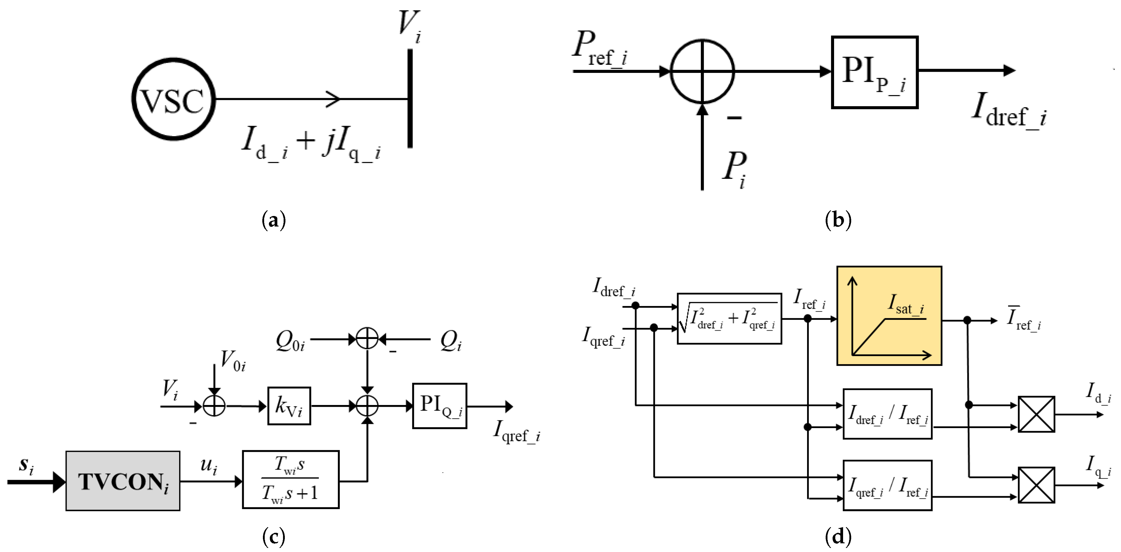
This paper primarily addresses the issues of delayed voltage recovery and transient voltage stability that arise from dynamic loads, such as induction motors, following a short-circuit fault in the power grid. Considering that these voltage problems last for around 2 s in general, this paper models the electromechanical time scale dynamics of grid-following VSCs. The focus is primarily on the outer loops for active and reactive power control, while neglecting the inner current control loop, switching processes, and other rapid dynamic processes, such as the phase-locked loop. As shown in Figure 1, and represent the d-axis and q-axis currents injected into the grid by the i-th VSC, indicating that the VSC is modeled as a controlled current source. , , and represent the active power, reactive power, and terminal voltage of the i-th VSC, respectively. and are the reference values for the active and reactive power outputs in the steady state. represents the terminal voltage of the i-th VSC in the rated state. and are the proportional-integral controllers for the active power and reactive power control loops, respectively. represents the reactive power–voltage droop control coefficient.
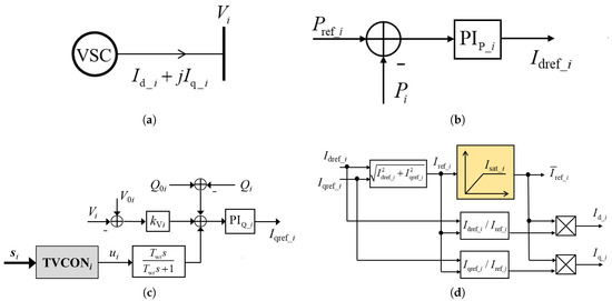
Figure 1.
Block diagram of VSC with auxiliary transient voltage controller. (a) Schematic diagram of VSC grid connection. (b) Active power control loop of VSC. (c) Reactive power–voltage control loop of VSC. (d) Current saturation limit loop of VSC.
This paper proposes to supplement a nonlinear controller (TVCON) with the reactive power control loop of the VSC, as illustrated in Figure 1c, to enhance its control performance regarding the system’s transient voltage. The TVCONi of the i-th VSC uses the real-time collected signal (vector) as the control input to generate the modulation signal . This signal then passes through a low-pass filter with a time constant , resulting in an additional reactive power deviation signal. The low-pass filter is employed to prevent the supplementary transient voltage controller from influencing the VSC’s static reactive power–voltage characteristics. Due to the capacity limit of the VSC, its operating current must remain less than or equal to the maximum allowable current. Therefore, the current commands generated by the active and reactive power control loops are typically subject to a saturation limit. This paper employs a proportional saturation method, as illustrated in Figure 1d, where and denote the d-axis and q-axis current reference values produced by the active and reactive power control loops of the i-th VSC, respectively; represents the operating current reference value; indicates the maximum permissible current, also known as the saturation current value, and is the operating current reference value after applying the saturation limit.
As shown in Figure 1d, the active and reactive currents outputted by the VSC during the transient process “compete” with one other. When the saturation current of the VSC is limited, a significant output of reactive current will inevitably lead to a reduction in the active current output. Although this is beneficial for the system’s transient voltage control, it may result in a significant imbalance in active power, potentially leading to issues with transient power angle or transient frequency stability. In fact, this “competition” relationship is also affected by the steady-state operating conditions of the VSC and the external system. For example, during midday when the solar photovoltaic output is high and is large, the transient control process must tackle the challenge of balancing active and reactive power. Conversely, at night, when the active power output from solar photovoltaic is zero (), the VSC’s capacity can be fully utilized for reactive current output during the transient process. Therefore, from the perspective of driving multiple VSCs to actively participate in the transient voltage control, the designed supplementary controllers should together accomplish two primary objectives: First, they must reasonably allocate each VSC’s control capacity to ensure an optimal transient voltage control effect while minimizing any adverse effects on the VSCs’ normal active power outputs. Second, they should guarantee that this control effectiveness is maintained across various pre-fault steady-state operating conditions of the VSCs, thereby providing adaptive functionality. Clearly, conventional fixed-parameter linear controllers cannot achieve both of these objectives. Therefore, this paper proposes TVCON, a nonlinear supplementary controller with a fixed structure but adjustable parameters, to fulfill these goals. The adaptive transient voltage control method based on the VSCs which incorporate TVCONs will be detailed in the following section.
2.2. General Description of Proposed Adaptive Transient Voltage Control Method
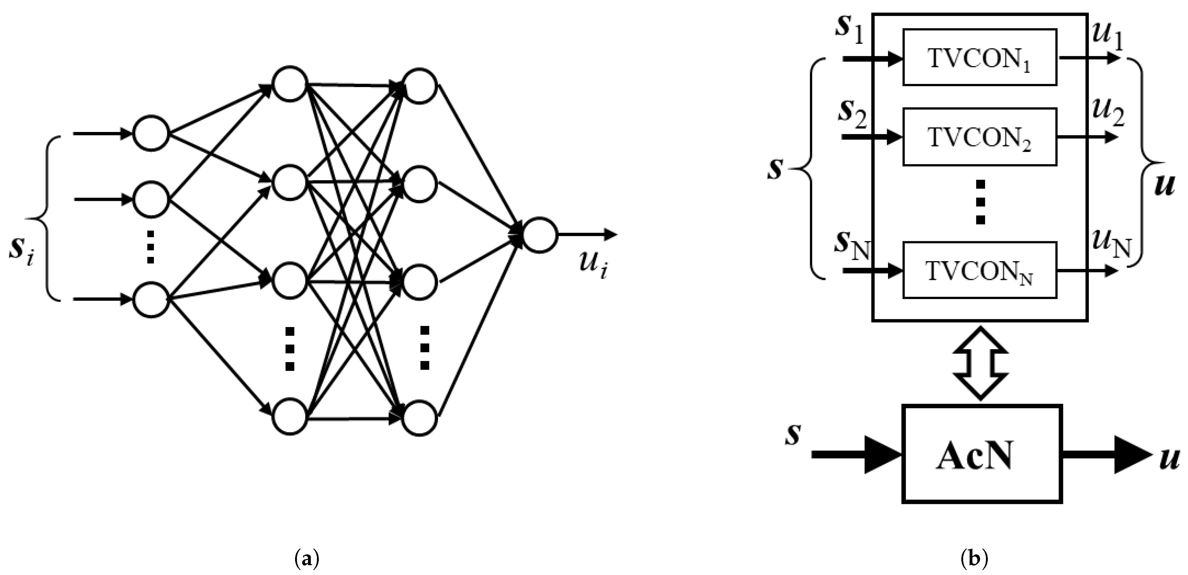
As described in the previous section, when the operating conditions of the system or the VSCs change over time (for example, when the reference active power output of the photovoltaic system varies with sunlight intensity), the transient voltage controllers designed for a specific operating condition may experience performance degradation or even failure. Therefore, this paper proposes periodically updating the parameters of the nonlinear controllers (TVCONs) online to mitigate the impact of such time-varying factors on control performance, thereby achieving adaptive transient voltage control. Figure 2a shows the structure of the nonlinear controller TVCON, where each TVCON is denoted by a multilayer neural network. As depicted in Figure 1c, the input vector for the i-th neural network controller TVCONi is , and its output is , with the connection weights between neurons represented as the vector . In this study, the periodically updated controller parameters correspond to the connection weight vectors of each neural network controller TVCONi.

Figure 2.
Structure diagram of networks TVCON and AcN. (a) Structure diagram of network TVCON. (b) Structure diagram of network AcN.
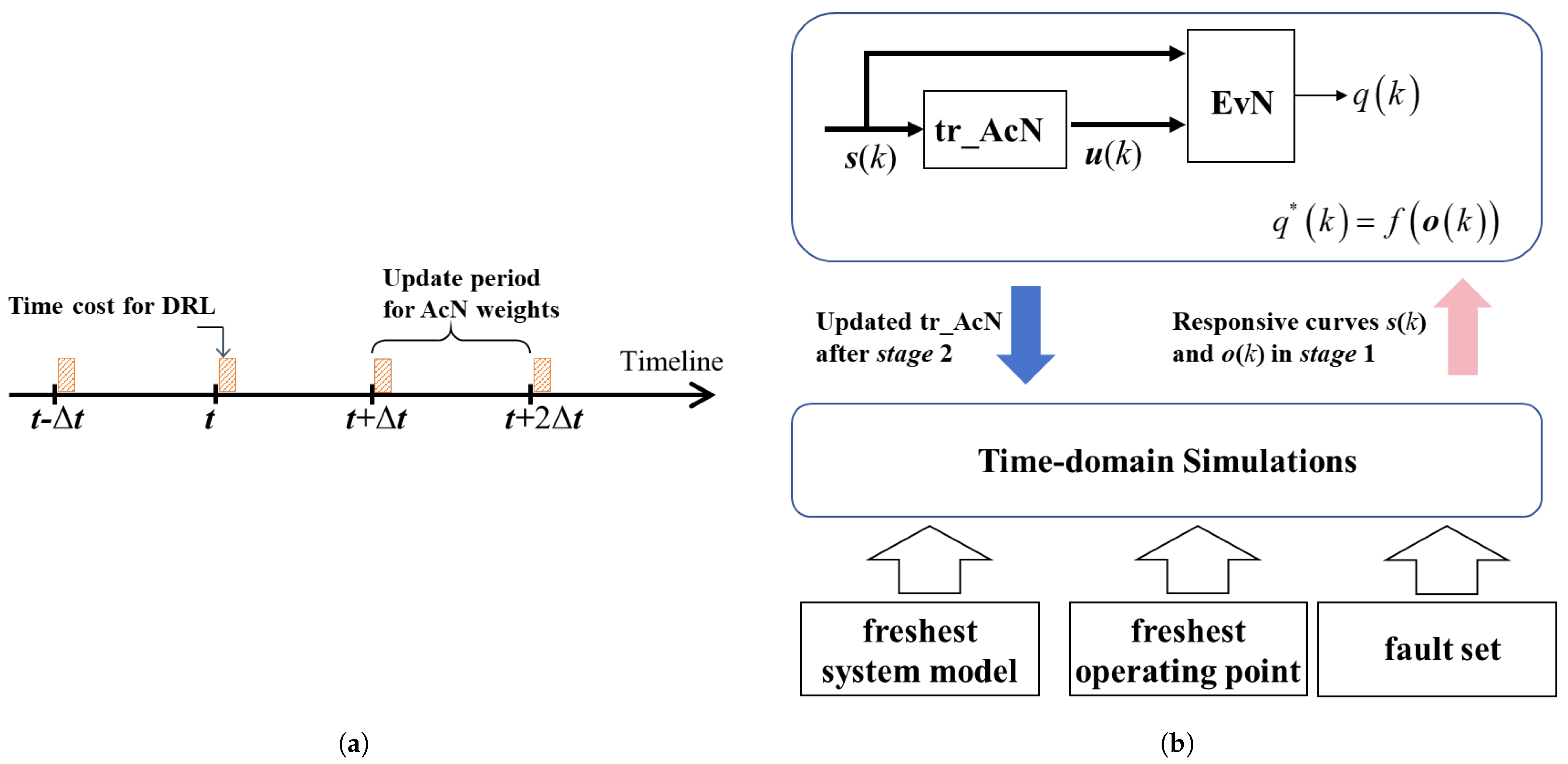
To facilitate the description of the controller parameter update strategy, the TVCONs equipped for the VSCs are equivalently and ensembly represented as one nonlinear controller AcN, as illustrated in Figure 2b, where the input vector consists of ; the output vector consists of ; N is the number of the VSCs actively participating in the transient voltage control; and represents the vector of periodically updated controller parameters, which includes . Figure 3a outlines the online periodic update strategy for the controller parameters proposed in this paper, where the controller parameters’ vector will be updated according to the following steps after every fixed time interval :
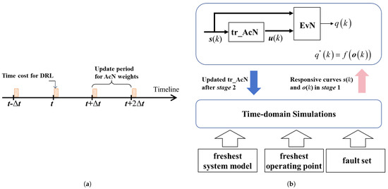
Figure 3.
Diagram of DRL-based adaptive transient voltage control framework. (a) Timing logic diagram of adaptive transient voltage control. (b) Scheme diagram of iterative process of DRL to update weights of AcN().
- (1)
- Online Training: First, the latest model and operating condition (operating point) information of the current actual system is collected from information systems such as the Energy Management System (EMS). Based on this information, the dynamic response curves of the current actual system under the anticipated fault set can be obtained through time-domain simulations. Therefore, using the dynamic response curves derived from the time-domain simulations, the connection weight vector of the nonlinear controller (which has the same structure as the actual nonlinear controller AcN) in the simulation model undergoes DRL training until convergence is achieved. The specific DRL objectives and processes will be introduced in Section 3.
- (2)
- Result Deployment: The connection weight vector , which has converged in the previous step, is then used to replace the connection weight vector of the actual AcN that performs the transient voltage control.
It is worth noting that to effectively track the system’s time-varying characteristics, the parameter update period is typically set to several minutes or tens of minutes (for example, 5 min or 15 min). As is well known, transient voltage issues are localized phenomena that can be accurately captured through time-domain simulations of the local power grid, with the external system aggregately represented. Consequently, the scale of the simulation is relatively limited. In addition, transient voltage instability or voltage recovery delays induced by faults generally present for around 2 s after fault clearance, indicating that the duration of time-domain simulations for transient voltage problems can also be relatively brief. In summary, although time-domain simulations must be repeatedly performed during parameter training, this will not significantly impact the computational efficiency.
3. Online Training Method for Controller Parameters Based on DRL
This paper proposes an online training method for the transient voltage controller parameters using DRL, as illustrated in Figure 3b: EvN denotes the evaluation network for DRL, while the action network uses the introduced in the previous section. It is important to emphasize again that the data used in the online DRL process are derived entirely from time-domain simulations of the actual system. For example, in Figure 3b, and represent the input vector of the action network and the system observation vector at the k-th simulation step, both obtained from the time-domain simulation. Additionally, and signify the outputs of the action network and evaluation network at the k-th simulation step.
3.1. Evaluation Network and Evaluation Function
In this paper, the evaluation network EvN has a multilayer neural network structure, with the connection weights between neurons represented by the vector . At the k-th simulation step, the EvN outputs , which evaluates the control performance of the action network . In fact, is an estimate of the following evaluation function that denotes the effectiveness of transient voltage control:
The system observation vector is defined as follows:
where represent the voltages at the target buses, and L is the number of target buses. denote the active power outputs of the N VSCs involved in transient voltage control.
The transient voltage control effectiveness evaluation function is defined as
where represents the target voltage value of the j-th target bus during the transient control process; Z denotes the total number of simulation steps that the dynamic observation variables span for calculating the evaluation function; and is the weight coefficient. Clearly, minimizing the evaluation function serves two primary purposes. The first summation term aims to bring the voltage of the target bus as close as possible to the target voltage value, thereby accelerating the voltage recovery during the transient process; the second summation term aims to penalize deviations of the VSCs’ active power from the reference values, thus preventing significant active power imbalances in the system that may arise from participation in transient voltage control.
Based on response curves derived from the online time-domain simulations, the value can be calculated at each simulation step.Then, together with the values of and at corresponding simulation steps, training samples for the evaluation network EvN can be generated. Moreover, since this is a supervised training process with samples, the training efficiency is relatively high.
3.2. Actor Network
As mentioned earlier, the action network in the DRL process shares the same structure as the nonlinear transient voltage controller AcN, as illustrated in Figure 2b. The is used exclusively for online training. Once convergence is achieved, its weight coefficients will be copied and transferred to AcN, thereby completing the adaptive transient voltage control, as depicted in Figure 3.
The input vector of (and AcN) consists of . Given the feedforward algebraic relationship between the input and output of , it is essential to account for the influence of historical states on transient voltage control to enhance the control performance. Therefore, the input signal for the TVCONi of the j-th VSC is selected as follows:
Equation (4) demonstrates that the input to the action network (nonlinear controller) includes system information from historical sampling points. It is important to note that, during deployment, the discrete sampling interval of the input–output signals for the nonlinear controller AcN aligns with the simulation step length of the time-domain simulation conducted during online training. Additionally, as indicated in Equation (4), the TVCONi of the i-th VSC uses only local measurement signals as inputs, while the online DRL training optimizes the adjustable parameters of all TVCONi (i = 1, 2,..., N) in a centralized manner, thereby achieving a distributed and collaborative transient voltage control effect.
3.3. Online DRL Process
As described in Section 2.2, the parameters of the nonlinear controller AcN will be updated periodically. Each period consists of two major computational stages: updating the weights of EvN and updating the weights of . These stages are conducted mutually and iteratively, followed by a stage to check the convergence criterion. These stages are listed as follows:
Stage 1: Updating the weights of EvN
- (1)
- Based on the latest system model (including the ), parameters, and information regarding operating point, perform time-domain simulations to obtain the system’s dynamic response curves under various fault disturbances;
- (2)
- Traverse the dynamic response curves to form the training sample set for the EvN, denoted ;
- (3)
- To minimize the following loss function, supervise the training of the EvN:
Stage 2: Updating the weights of
- (4)
- After completing iterations of the EvN training, fix its weight coefficients. Then, using the time-domain simulation data, the action network is trained via backpropagation through the evaluation network to minimize that is, the loss function used for training , and its weight coefficients are updated as follows:where represents the increment of the weight coefficients for the action network in this round of training.
Stage 3: Checking the convergence criterion
- (5)
- Compare the loss functions of the evaluation network and the action network from the previous and current training rounds to determine whether convergence has been achieved. If convergence is reached, copy the weight coefficients of the action network and deploy them to the nonlinear controller AcN, thereby completing the parameter update for AcN in this cycle; otherwise, return to Step (1) with the updated weight coefficients for the .
In summary, the weights of AcN will be online updated in each period by performing the following DRL process: Stage 1→Stage 2→Stage 3→Stage 1→Stage 2→Stage 3→…, until the convergence criterion is met in Stage 3. In each parameter update cycle, the initial weight coefficients of EvN and are set to the values that converged in the previous cycle. This means that the parameter training in each cycle is an incremental learning process based on the results from prior training. Given that the system’s operating state typically does not change significantly over short periods, this incremental learning approach can expedite the parameter training process.
4. Simulation Verification and Analysis
4.1. Test System Setup
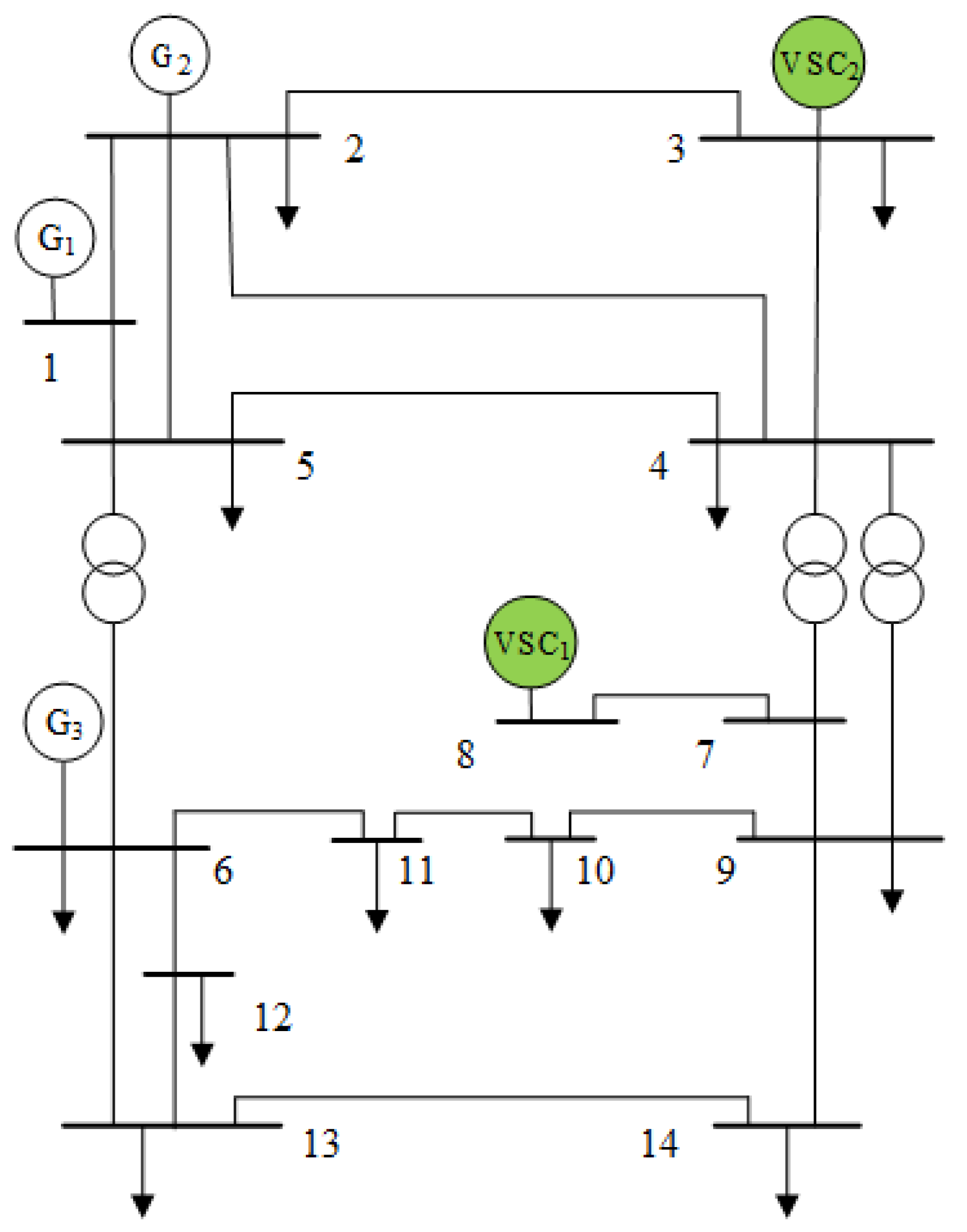
To validate the proposed DRL-based adaptive transient voltage control method, simulations are conducted using a modified IEEE 14-Bus system [29]. The modifications mainly involve replacing the two synchronous generators at Buses 3 and 8 with VSCs, and increasing the active load at Bus 4 by 40%, as illustated in Figure 4, with each number representing a specific bus within the power system. Table 1 presents the parameter settings for the two VSCs. In the absence of the TVCON on the two VSCs, transient voltage issues arise at Bus 4 during a three-phase fault in the adjacent area. Therefore, in this paper, we install TVCON on both VSCs, and their parameters are adjusted online using the proposed method to achieve collaborative and adaptive transient voltage control, improving the transient voltage quality at Bus 4.
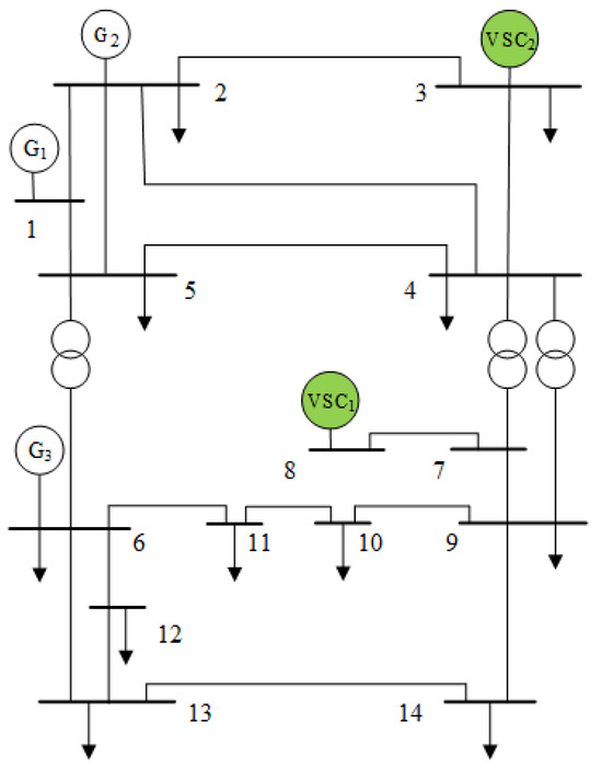
Figure 4.
Diagram of modified IEEE 14-Bus system.

Table 1.
VSC parameter settings.
In order to emphasize the importance of adaptive control, as well as the efficiency and effectiveness of the proposed method, two comparative simulation scenarios are set as follows.
Case 1: In the steady state, the active and reactive power outputs of the two VSCs are , , , ;
Case 2: In the steady state, the active and reactive power outputs of the two VSCs are , , , .
Except for the active and reactive power outputs of the VSCs, the steady-state active power output, terminal voltage, and load at each bus remain consistent in both Case 1 and Case 2. In addition, the load at Bus 4 consists of an induction motor and a constant impedance, with a ratio of 1:1, while the loads at the other buses are represented solely as constant impedances. It is assumed that the system initially operates under the scenario of Case 1, and the supplementary nonlinear controller, TVCON, for the two VSCs, has already been trained in this scenario. The simulation primarily aims to verify the convergence characteristics of the proposed online training method for the controller parameters and to assess the control performance of the controller after convergence when the system transitions from Case 1 to Case 2.
From both the perspectives of control effectiveness and training complexity, the number of layers and neurons in the neural network used as a TVCON cannot be excessively large or small. However, there is currently no straightforward method with which to easily configure the structure of neural network-based controllers. Thus, based on the trial-and-error method, the TVCON1 and TVCON2, installed for the two VSCs, utilize the four-layer feedforward neural network structure, with 10 neurons and the sigmoid activation function in both the second and third layers. The sampling rate is set at 50 Hz in this study. Specifically, the training of AcN is based on the data obtained from the time-domain simulation. Therefore, the selected faults must ensure that the transient voltage dynamics of the targeted buses are fully excited. Thus, the anticipated fault set includes instantaneous three-phase short circuits at 30%, 60%, and 90% along lines 5-4, 2-4, and 3-4, respectively, each lasting for 80 ms. The duration of the time-domain simulation from the fault occurrence is set to 3 s, with a simulation step size of 20 ms. In the simulated system, the target bus is Bus 4; therefore, in Equation (3), , , and the weight coefficient in the loss function is set to 0.65, with . All simulations are conducted on a desktop computer (Dell Technologies Inc., Round Rock, TX, USA) equipped with an Intel(R) Core(TM) i7-14700KF 3.40 GHz processor (3.4 GHz) and 32 GB of memory, using the Matlab R2024a (Version 24.1.0) platform.
4.2. Simulation Analysis
4.2.1. Online DRL Training Results
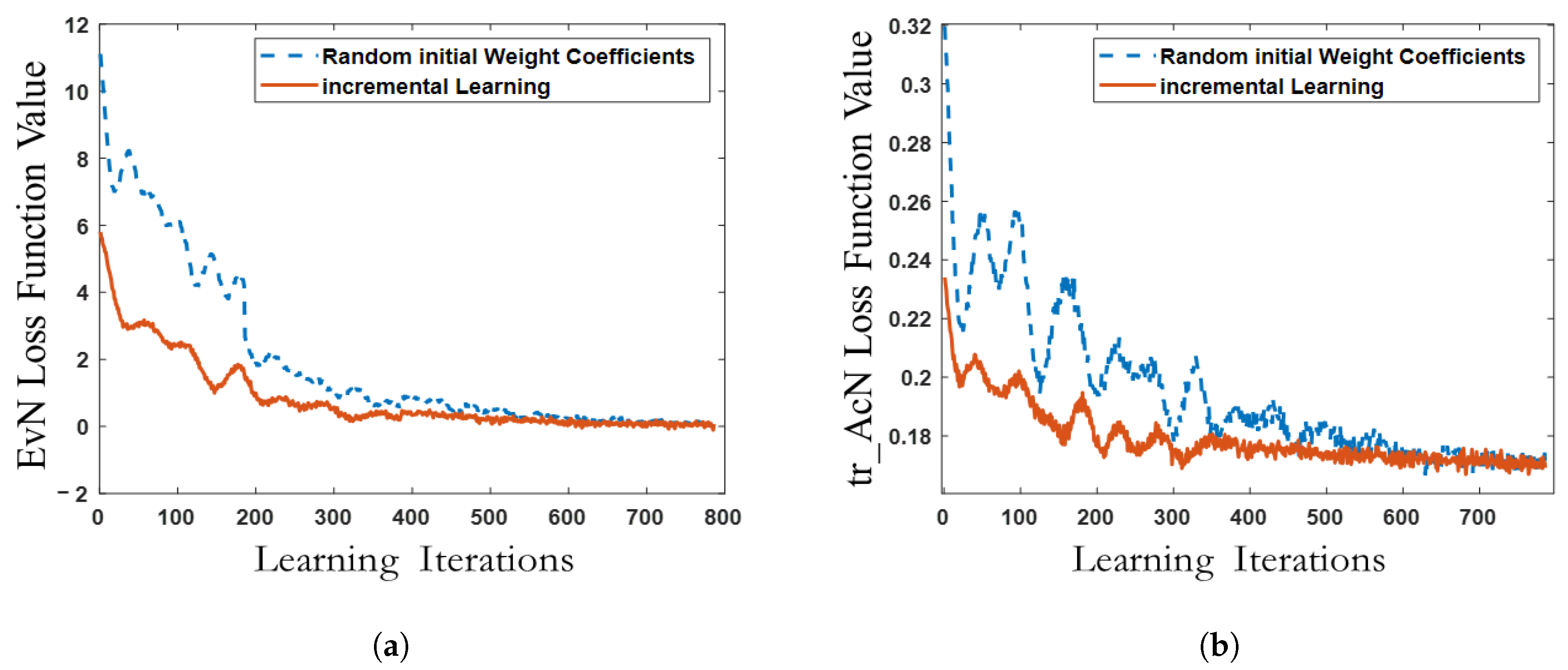
After the system’s operating scenario transitions from Case 1 to Case 2, the weight coefficients of EvN and are trained using the proposed online DRL method. Figure 5a,b show the convergence of the loss functions for EvN and with respect to the number of learning iterations. In each iteration, the loss function values at the end of Stage 1 and Stage 2, as described in Section 3.3, are used to generate Figure 5. The red solid line in Figure 5 represents the convergence process of DRL employed to update the weights of AcN when the optimal weight coefficients from Case 1 are used as the initial weights for EvN and . This approach is referred to as the incremental learning method adopted in this study. Furthermore, Figure 5a,b compare the convergence of the loss functions when the incremental learning method is applied versus when random initial weight coefficients are used for EvN and . It is evident that the learning process with random initial weight coefficients requires approximately 600 iterations to converge, while the incremental learning method presented in this paper only necessitates about 320 iterations to achieve convergence, demonstrating superior convergence characteristics and enhanced learning efficiency.
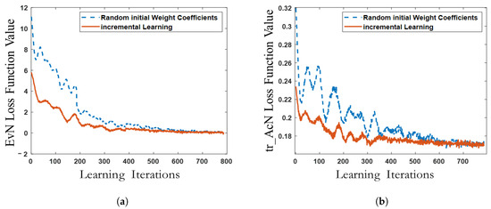
Figure 5.
Converging curve of training EvN and AcN. (a) Converging curve of training EvN. (b) Converging curve of training AcN.
The time consumption of the online training process above is statistically analyzed, revealing that the average training time per round of DRL is 0.48 s. Each round involves nine time-domain integrations, which take approximately 0.36 s. The remaining time is primarily allocated to update the weight coefficients of the EvN and , which requires about 0.12 s. Overall, the learning process with random initial weight coefficients takes approximately 290 s, while the incremental learning method used in this paper requires only 150 s. Therefore, if the parameter update cycle for the transient voltage controller is set to 5 min or even 15 min, the proposed online reinforcement learning method for updating controller parameters demonstrates adequate timeliness. In fact, if parallel computing techniques or more powerful computing platforms are employed, and the computational program is further optimized, the time required for online training can be significantly reduced. In this study, we also tried to update the weights of AcN by formulating an optimization problem that is solved using conventional model-based optimization methods, such as sequential quadratic programming (SQP). However, the search process of SQP is highly time-consuming and often fails to converge due to the high dimensionality of the search space and the reliance on numerical gradients. This demonstrates that employing the DRL process to update the weights of AcN online is both computationally efficient and feasible.
4.2.2. Analysis of Transient Voltage Control Effect
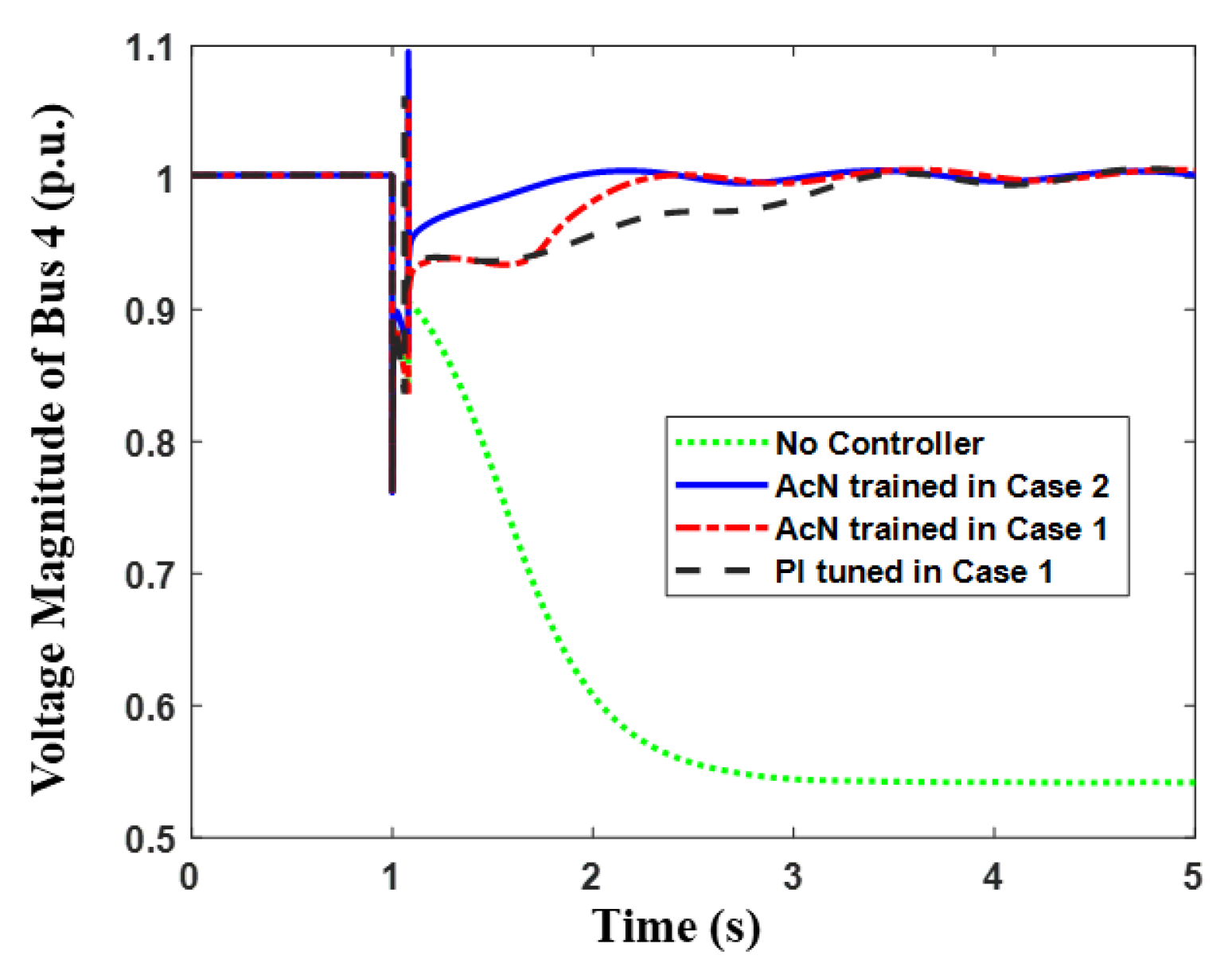
When the system operates in the scenario of Case 2, a three-phase instantaneous short circuit occurs at 50% of the distance along the line 5-4, with a fault duration of 80 ms. This paper compares the control effects when the VSCs are supplementarily controlled by four different transient voltage controllers: first, no transient voltage control is applied; second, the weight coefficients of the transient voltage controller AcN are set according to the parameter training results from Case 1 (i.e., after the system transitions from Case 1 to Case 2, the controller parameters remain unchanged); third, the weight coefficients of the transient voltage controller AcN are updated based on the parameter training results from Case 2 (i.e., after the system transitions from Case 1 to Case 2, the controller parameters are adjusted accordingly); lastly, traditional proportional–integral (PI) controllers are employed. Specifically, when the PI control is implemented, each voltage source converter (VSC) is equipped with a PI controller that uses the terminal voltage of the VSC as an input to generate the reactive power modulation signal for the VSC, similar to the process illustrated in Figure 1c. Moreover, all coefficients of the PI controllers are tuned in coordination while the system operates under Case 1, utilizing the trial-and-error method. These coefficients remain constant even as the system transitions to different operating conditions.
Figure 6 compares the transient voltage control effects associated with the four types of controllers mentioned above. It is clear that when no transient voltage controller is added to the VSC, the voltage at Bus 4 becomes unstable following the short-circuit disturbance in the system. The main reason for this instability is the insufficient transient reactive power supplied by the system, which causes the slip of the induction motor load at Bus 4 to continuously increase, ultimately leading to a locked rotor phenomenon. Furthermore, with the optimal parameters trained in Case 2, the transient voltage at Bus 4 recovers rapidly after fault clearance, confirming the effectiveness of the proposed nonlinear controller. However, when the transient voltage controller uses the optimal parameters from the Case 1 scenario, although the transient voltage at Bus 4 remains stable, its recovery process is noticeably slower compared to the transient voltage recovery process observed when the optimal parameters from Case 2 are applied, indicating a clear voltage delay recovery phenomenon. It is also observed that the traditional PI controllers demonstrate the least effective performance in controlling the voltage. Quantitatively, the average voltage dips during the fault period are 0.162, 0.195, and 0.202, respectively, for AcN trained in Case 2, AcN trained in Case 1, and PI tuned in Case 1. In other words, the online adaptation for AcN helps to reduce the voltage dip by nearly 20%, and this percentage increases to almost 25% when using the benchmark voltage dip produced by the PI controllers. Furthermore, AcN with parameters adapted to Case 2 raises the voltage above 0.95 once the fault is cleared. In contrast, AcN with parameters trained in Case 1, along with the PI controllers, takes approximately 1.75 s and 1.98 s, respectively, to restore the voltage to 0.95. Consequently, the quantitative analysis demonstrates that the proposed DRL-based adaptive transient control is more effective in enhancing transient voltage quality compared to fixed-parameter controllers.
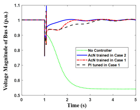
Figure 6.
Variation of Bus 4’s voltage.
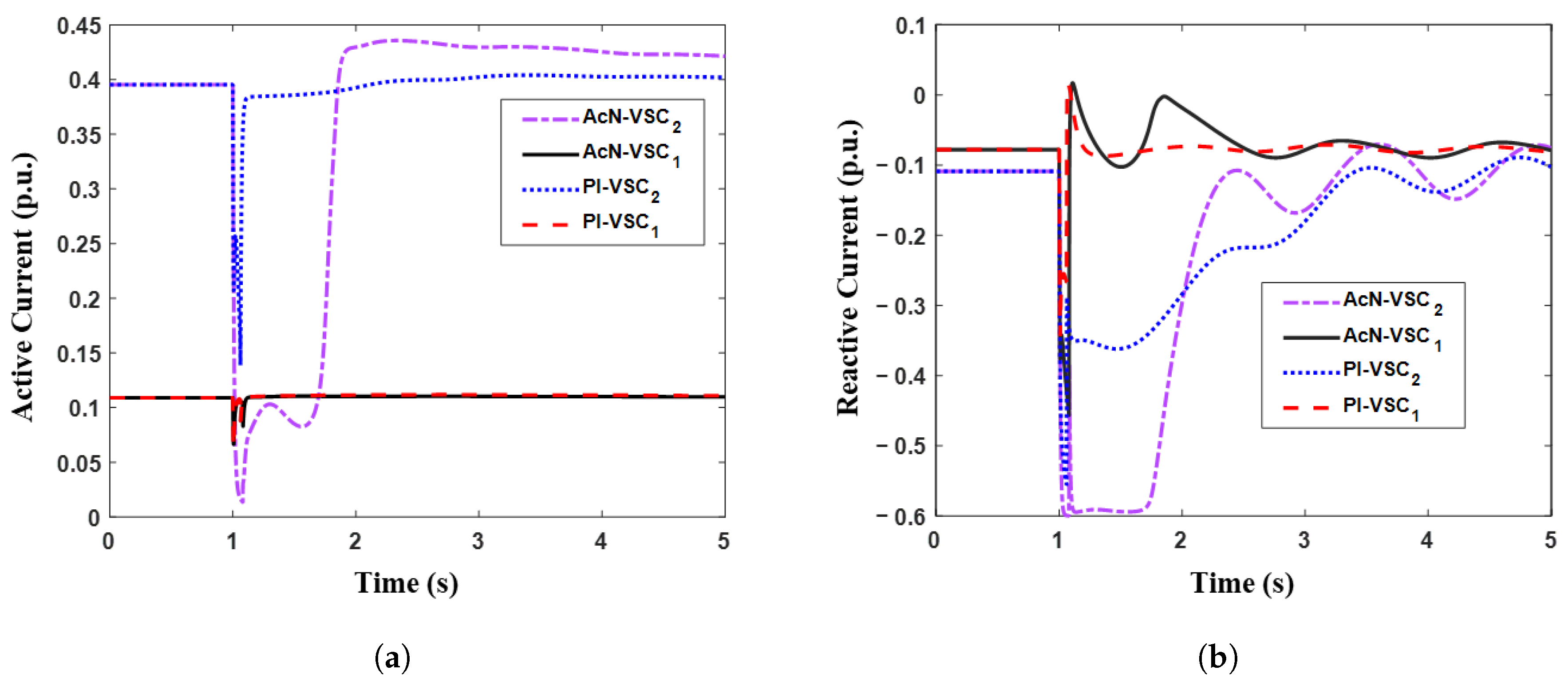
Figure 7 and Figure 8 compare the active and reactive currents outputted by the VSCs with different transient voltage controllers. In the scenario of Case 1, exhibits a higher steady-state active power output, while shows a lower steady-state active power output. Consequently, the transient voltage controller trained under the Case 1 scenario tends to “squeeze” the control capacity of while minimizing the utilization of ’s reactive power output. This strategy prevents from allocating its limited capacity to transient reactive power output, which could cause a significant deviation of its transient active power from the command value. In contrast, in the scenario of Case 2, the steady-state power outputs of and are reversed compared to Case 1. If the transient voltage controller continues to apply the optimal parameters trained in Case 1 while the system has transitioned to the scenario of Case 2, it will inappropriately “squeeze” the heavily loaded while neglecting the favorable transient reactive power output conditions of . Figure 7 shows that ’s active current drops from 0.4 p.u. to nearly zero for ~1 s, allowing for increased reactive current output. Conversely, ’s active current remains relatively low and stable, contributing minimal inductive reactive current during the voltage recovery process, thereby underutilizing its control capacity. Specifically, the traditional PI controllers tuned in Case 1 appear to inappropriately utilize the current capacities of the VSCs when the system transitions to operate in Case 2. Figure 7 and Figure 8 demonstrate that the active current of is significantly reduced by the PI controllers; however, its reactive current does not exhibit a comparable level of aggression. This discrepancy is the reason why the PI controllers are less effective than the proposed AcN controller in managing transient voltage.

Figure 7.
Output currents of VSCs when both AcN and PI are trained (tuned) in Case 1. (a) Active current. (b) Reactive current.
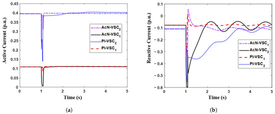
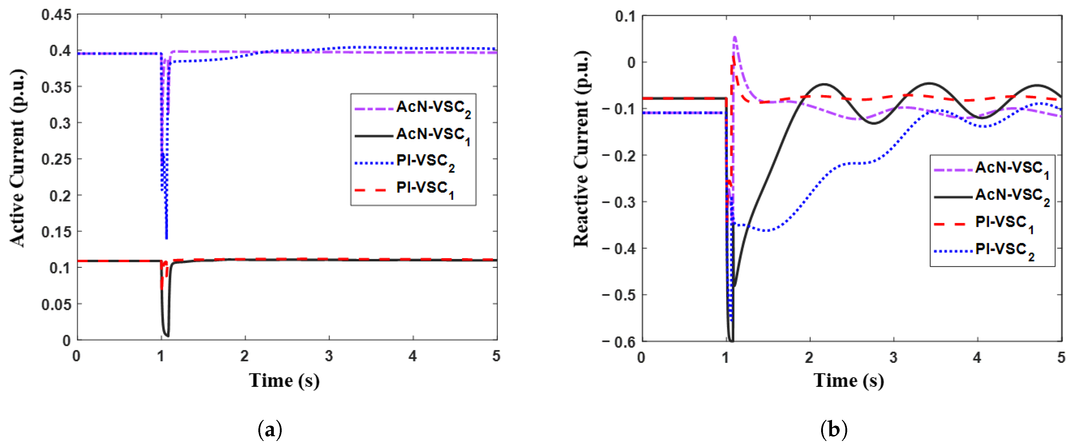
Figure 8.
Output currents of VSCs when AcN is trained in Case 2 while PI is tuned in Case 1. (a) Active current. (b) Reactive current.
When the system operates in the Case 2 scenario and the transient voltage controller employs the optimal parameters just trained under this scenario, the active and reactive currents outputted by and are shown in Figure 8. It is evident that the online learning process successfully captures the transition in operating conditions— shifts from a heavily loaded state to a lightly loaded one, while transitions from a lightly loaded state to a heavily loaded one. Consequently, the controller AcN adaptively adjusts its weight coefficients, fully utilizing ’s transient reactive current output while ensuring that the transient active power of the heavily loaded remains relatively close to its command value.
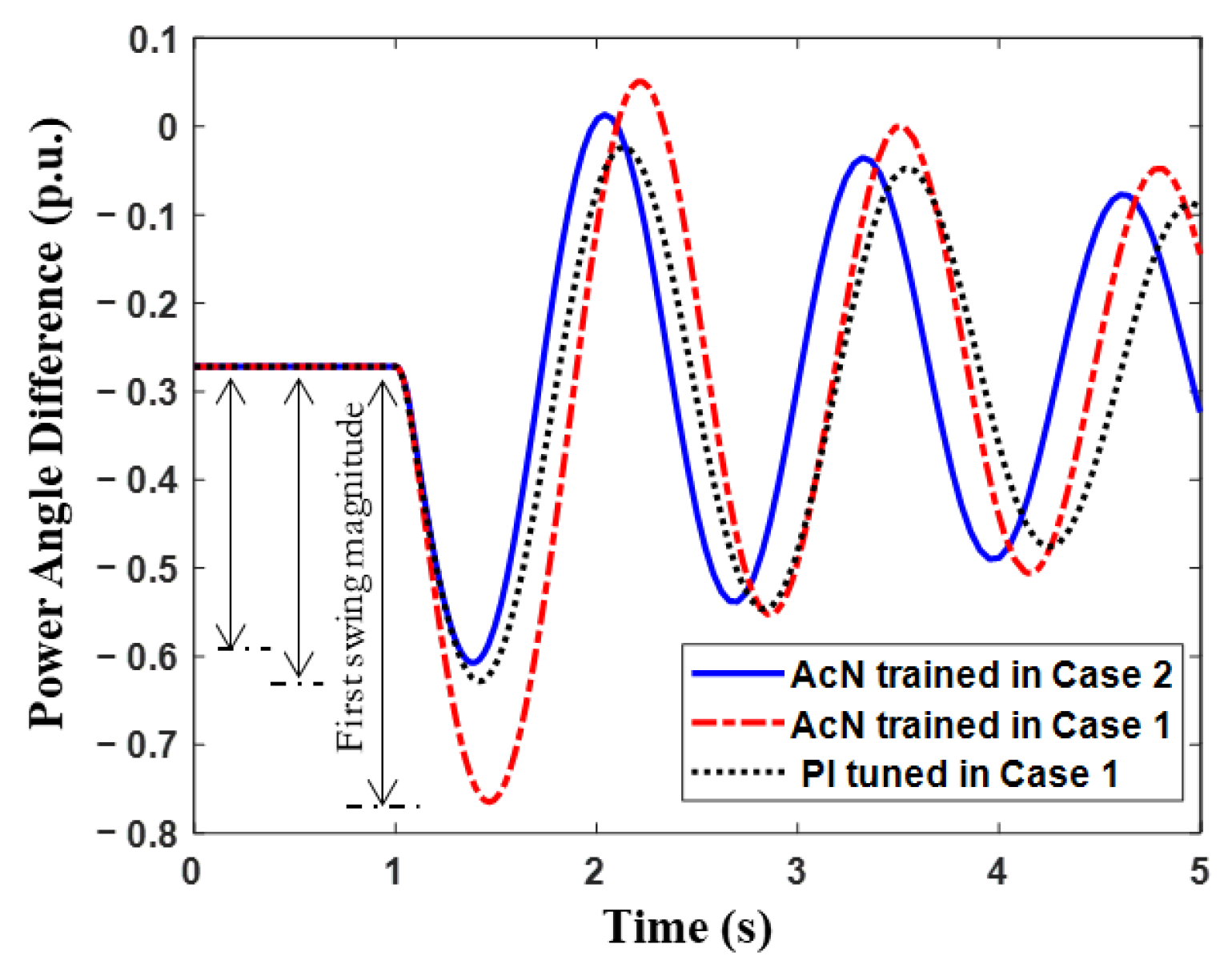
In fact, when VSCs engage in transient voltage control, significant deviations in their transient active power from the command value can lead to severe active power imbalances within the system, potentially resulting in transient power angle or frequency stability issues. For example, Figure 9 shows the relative power angle swing curve between synchronous generators and . It can be observed that when the transient voltage controller uses the optimal parameters from the Case 1 scenario, it induces a more substantial active power imbalance disturbance. This, in truth, results in a significantly larger initial swing phase angle difference between the two synchronous generators compared to when the AcN utilizes the optimal parameters from the Case 2 scenario, thereby increasing the risk of transient power angle instability in the system. However, since the PI controllers do not significantly reduce the active current of for an extended period, the resulting initial power angle swing magnitude is not as substantial as that produced by the AcN controller with optimal parameters derived in Case 1.
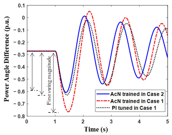
Figure 9.
Power angle difference between synchronous generators and .
5. Conclusions
This paper proposes a DRL-based adaptive transient voltage control method that takes into account the limited control capacity of the VSC. The primary features and contributions of the proposed method are reflected in two key aspects; the first is the use of neural network-based controllers combined with centralized weight optimization, which enables the achievement of favorable control effects even in highly nonlinear systems with distributed controllers. The second is the implementation of a DRL-based adaptation process that periodically updates the weights of the controllers, ensuring that they maintain excellent performance in managing transient voltage, even as the operating conditions of the system evolve over time. The main conclusions drawn from this paper are as follows.
- (1)
- By utilizing a locally scaled equivalent grid (with a simulation duration of approximately 2–3 s) and integrating incremental DRL (with supervised learning for the evaluation network), the time-domain simulation-based training of the transient voltage controller parameters can exhibit quite acceptable convergence and timeliness for the online application.
- (2)
- The distributed TVCONs, whose parameters are optimized (trained) in a centralized manner, can work cooperatively to manage the transient voltage of the system. The voltage dip at the targeted bus can be reduced by approximately 25% compared to that produced by the conventional PI controllers. Furthermore, TVCONs can restore the voltage to 0.95 as soon as the fault disappears, while the PI controllers take around 2 s to achieve this voltage level.
- (3)
- DRL-based periodic updating of the transient voltage controller parameters can effectively account for the capacity limit of each VSC and reasonably allocate their control efforts judiciously during the transient voltage control process, in accordance with the system’s real-time steady-state operating point. This method ensures that the system’s transient voltage recovers as rapidly as possible following a disturbance, optimally utilizes the limited control capacity of each VSC, and minimizes the impact on the VSC’s active power dynamics. Consequently, it helps to prevent secondary issues such as transient power angle or frequency instability.
Author Contributions
Conceptualization, G.X. and H.Y.; Methodology, G.X. and H.Y.; Software, D.K. and Y.L.; Data curation, Y.L. and J.G.; Writing—original draft, G.X. and J.G.; Writing—review & editing, D.K., Y.L. and S.L.; Supervision, H.Y. and S.L. All authors have read and agreed to the published version of the manuscript.
Funding
This work was supported by the major technology project of China Southern Power Grid, “Research on the coupling mechanism and control method of large disturbance stabilization of modern power system” (Project No. 0000002022030101XT00031).
Institutional Review Board Statement
Not applicable.
Informed Consent Statement
Not applicable.
Data Availability Statement
The raw data supporting the conclusions of this article will be made available by the authors on request.
Conflicts of Interest
Guanghu Xu and Huanhuan Yang were employed by China Southern Power Grid. The remaining authors declare that the research was conducted in the absence of any commercial or financial relationships that could be construed as a potential conflict of interest.
References
- Zhu, S.; Liu, K.; Qin, L.; Li, G.; Hu, X.; Liu, D. Analysis of Transient Stability of Power Electronics Dominated Power System: An Overview. Proc. CSEE 2017, 37, 3948–3962+4273. [Google Scholar] [CrossRef]
- Peng, Q.; Jiang, Q.; Yang, Y.; Liu, T.; Wang, H.; Blaabjerg, F. On the Stability of Power Electronics-Dominated Systems: Challenges and Potential Solutions. IEEE Trans. Ind. Appl. 2019, 55, 7657–7670. [Google Scholar] [CrossRef]
- Khan, A.; Hosseinzadehtaher, M.; Shadmand, M.B.; Bayhan, S.; Abu-Rub, H. On the Stability of the Power Electronics-Dominated Grid: A New Energy Paradigm. IEEE Ind. Electron. Mag. 2020, 14, 65–78. [Google Scholar] [CrossRef]
- Holttinen, H.; Kiviluoma, J.; Flynn, D.; Smith, J.; Orths, A.; Eriksen, P.; Cutululis, N.; Söder, L.; Korpås, M.; Estanqueiro, A.; et al. System Impact Studies for Near 100% Renewable Energy Systems Dominated by Inverter Based Variable Generation. IEEE Trans. Power Syst. 2022, 37, 3249–3258. [Google Scholar] [CrossRef]
- Mao, A.; Ma, J.; Kuai, S.; Zhou, Q.; Zhao, S.; Chen, C.; Yang, X. The Evolution Mechanism of System Transient Stability and Voltage Stability After High Proportion of Renewable Energy Replaces Conventional Power Sources. Proc. CSEE 2020, 40, 2745–2756. [Google Scholar] [CrossRef]
- Ortiz-Villalba, D.; Rahmann, C.; Alvarez, R.; Canizares, C.A.; Strunck, C. Practical Framework for Frequency Stability Studies in Power Systems With Renewable Energy Sources. IEEE Access 2020, 8, 202286–202297. [Google Scholar] [CrossRef]
- Chen, J.; Zuo, H.; Yu, Q.; Qi, L.; Zhu, M. Influence of Dynamic Characteristics of Induction Motor on Voltage Sag Caused by Short Circuit Fault. J. Electr. Eng. Technol. 2020, 15, 1511–1519. [Google Scholar] [CrossRef]
- Li, Q.; Lin, T.; Du, H.; Fu, X.; Li, J.; Xu, X.; Li, D.; Rao, Y. Emergency Control Strategy for Transient Voltage Stability in DC-Terminal Power Systems. Power Autom. Equip. 2024, 44, 195–202. [Google Scholar] [CrossRef]
- Liu, Y.; Yao, L.; Liao, S.; Yu, H.; Liu, H.; Wang, K.; Li, X. Distributed Photovoltaic and Energy Storage Participation in Transient Voltage Control of DC-Terminal Near Distribution Networks. Grid Technol. 2023, 47, 1250–1261. [Google Scholar] [CrossRef]
- Ávila Martínez, R.E.; Renedo, J.; Rouco, L.; Garcia-Cerrada, A.; Sigrist, L.; Qoria, T.; Guillaud, X. Fast Voltage Boosters to Improve Transient Stability of Power Systems With 100% of Grid-Forming VSC-Based Generation. IEEE Trans. Energy Convers. 2022, 37, 2777–2789. [Google Scholar] [CrossRef]
- Xu, H.; Zhang, X.; Liu, F.; Shi, R.; Yu, C.; Cao, R. A Reactive Power Sharing Strategy of VSG Based on Virtual Capacitor Algorithm. IEEE Trans. Ind. Electron. 2017, 64, 7520–7531. [Google Scholar] [CrossRef]
- Wu, T.; Jiang, Q.; Liu, F.; Huang, M.; Xie, X. Synchronization Stability of Grid-Tied VSC With Control Limiters: Models, Solutions, and Boundaries. IEEE Trans. Energy Convers. 2024, 1–11. [Google Scholar] [CrossRef]
- Zhuang, K.; Xin, H.; Hu, P.; Wang, Z. Current Saturation Analysis and Anti-Windup Control Design of Grid-Forming Voltage Source Converter. IEEE Trans. Energy Convers. 2022, 37, 2790–2802. [Google Scholar] [CrossRef]
- Mirza, C.; Abbas, M.; Idris, S.; Khan, Y.; Alameer, A.; Rajab, A.; Ismailov, S.; Faqihi, A.; Abbas, A.; Ben Khedher, N. Intelligent computing technique to analyze the two-phase flow of dusty trihybrid nanofluid with Cattaneo-Christov heat flux model using Levenberg-Marquardt Neural-Networks. Case Stud. Therm. Eng. 2025, 68, 105891. [Google Scholar] [CrossRef]
- Moayedi, H.; Mukhtar, A.; Ben Khedher, N.; Elbadawi, I.; Ben Amara, M.; TT, Q.; Khalilpoor, N. Forecasting of energy-related carbon dioxide emission using ANN combined with hybrid metaheuristic optimization algorithms. Eng. Appl. Comput. Fluid Mech. 2024, 18, 232250. [Google Scholar] [CrossRef]
- Khan, M.; Ghodhbani, R.; Taha, T.; Al-Yarimi, F.; Zeeshan, A.; Ijaz, N.; Ben Khedher, N. Advanced intelligent computing ANN for momentum, thermal, and concentration boundary layers in plasma electro hydrodynamics Burgers fluid. Int. Commun. Heat Mass Transf. 2024, 159, 108195. [Google Scholar] [CrossRef]
- Pandey, U.; Pathak, A.; Kumar, A.; Mondal, S. Applications of artificial intelligence in power system operation, control and planning: A review. Clean Energy 2023, 7, 1199–1218. [Google Scholar] [CrossRef]
- Alhamrouni, I.; Abdul Kahar, N.H.; Salem, M.; Swadi, M.; Zahroui, Y.; Kadhim, D.J.; Mohamed, F.A.; Alhuyi Nazari, M. A Comprehensive Review on the Role of Artificial Intelligence in Power System Stability, Control, and Protection: Insights and Future Directions. Appl. Sci. 2024, 14, 6214. [Google Scholar] [CrossRef]
- Sarajcev, P.; Kunac, A.; Petrovic, G.; Despalatovic, M. Artificial Intelligence Techniques for Power System Transient Stability Assessment. Energies 2022, 15, 507. [Google Scholar] [CrossRef]
- Gao, H.; Jiang, S.; Li, Z.; Wang, R.; Liu, Y.; Liu, J. A Two-Stage Multi-Agent Deep Reinforcement Learning Method for Urban Distribution Network Reconfiguration Considering Switch Contribution. IEEE Trans. Power Syst. 2024, 39, 7064–7076. [Google Scholar] [CrossRef]
- Zeng, H.; Zhou, Y.; Guo, Q.; Cai, Z.; Sun, H. Distributed Deep Reinforcement Learning-based Approach for Fast Preventive Control Considering Transient Stability Constraints. CSEE J. Power Energy Syst. 2023, 9, 197–208. [Google Scholar] [CrossRef]
- Hu, Z.; Shi, Z.; Zeng, L.; Yao, W.; Tang, Y.; Wen, J. Knowledge-enhanced deep reinforcement learning for intelligent event-based load shedding. Int. J. Electr. Power Energy Syst. 2023, 148, 108978. [Google Scholar] [CrossRef]
- Wang, T.; Tang, Y. Data-model driven rescheduling considering both rotor angle stability and transient voltage stability constraints. IET Renew. Power Gener. 2022, 16, 1509–1521. [Google Scholar] [CrossRef]
- Hu, Z.; Su, R.; Veerapandiyan, V.; Huang, L.; Ma, R. Resilient Frequency Regulation for Microgrids Under Phasor Measurement Unit Faults and Communication Intermittency. IEEE Trans. Ind. Inform. 2025, 21, 1941–1949. [Google Scholar] [CrossRef]
- Zhang, B.; Li, D.; Wang, Y.; Yan, X. Self-adaptable reactive power-voltage controller for virtual synchronous generators. J. Eng. 2019, 2019, 2969–2973. [Google Scholar] [CrossRef]
- Sun, J.; Cai, W.; Guo, Q. Improvement of transient stability performance of VSG considering power angle stability and fault current limiting. Electr. Mach. Control 2024, 28, 35–48. [Google Scholar] [CrossRef]
- Li, L.; He, G.; Jia, X.; Fan, H.; Hu, W.; Zhao, Z. VSG Optimal Control Method Based on Improved Power Control Loop. Control Eng. China 2023, 30, 385–392. [Google Scholar] [CrossRef]
- Hu, W.; Wu, Z.; Sun, C.; Song, Y.; Yuan, K. Modeling and parameter setting method for grid-connected inverter of energy storage system based on VSG. Electr. Power Autom. Equip. 2018, 38, 13–23. [Google Scholar] [CrossRef]
- Iyambo, P.; Tzoneva, R. Transient stability analysis of the IEEE 14-bus electric power system. In Proceedings of the AFRICON 2007, Windhoek, South Africa, 26–28 September 2007; pp. 1–9. [Google Scholar] [CrossRef]
Disclaimer/Publisher’s Note: The statements, opinions and data contained in all publications are solely those of the individual author(s) and contributor(s) and not of MDPI and/or the editor(s). MDPI and/or the editor(s) disclaim responsibility for any injury to people or property resulting from any ideas, methods, instructions or products referred to in the content. |
© 2025 by the authors. Licensee MDPI, Basel, Switzerland. This article is an open access article distributed under the terms and conditions of the Creative Commons Attribution (CC BY) license (https://creativecommons.org/licenses/by/4.0/).