Article

Evolution of Real-Time Dynamics Monitoring of Colombian Power Grid Using Wide-Area Monitoring System and High-Speed Big Data Analytics

by
Samuel Bustamante
,
Jaime D. Pinzón
*,† and
Daniel Giraldo-Gómez
XM S.A. E.S.P., Medellín 050021, Colombia
*
Author to whom correspondence should be addressed.
These authors contributed equally to this work.
Sustainability 2025, 17(9), 3848; https://doi.org/10.3390/su17093848
Submission received: 6 December 2024 / Revised: 22 January 2025 / Accepted: 27 January 2025 / Published: 24 April 2025

Abstract

:
To ensure the reliability and security of Colombia’s national power system, there is an ongoing necessity for upgrades in monitoring and protection mechanisms. Approximately sixteen years ago, the introduction of synchrophasor measurements enabled the swift detection of potentially network-detrimental events. Subsequent advancements have seen the deployment of Phasor Measurement Units (PMUs), currently tallying 150 across 25 substations, facilitating real-time monitoring and analysis. The growth of the PMU network is pivotal for the modernization of the National Control Center, particularly in the face of complexities introduced by renewable energy sources. There is an increasing demand for data analytics platforms to support operators in responding to threats. This paper explores the development of the Colombian Wide-Area Measurement System (WAMS) network, highlighting its milestones and advancements. Significant contributions include the technological evolution of the WAMS for real-time monitoring, an innovative high-speed data analytics strategy, and tools for the monitoring of frequency, rate of change of frequency (RoCoF), angular differences, oscillations, and voltage recovery, alongside industry-specific criteria for real-time assessment. Implemented within an operational WAMS, these tools enhance situational awareness, thereby assisting operators in decision-making and augmenting the power system’s reliability, security, and efficiency, underscoring their significance in modernization and sustainability initiatives.

1. Introduction

As electrical power systems (EPSs) expand and integrate new technologies, their operation, planning, and analysis become increasingly complex. Maintaining power flexibility, frequency stability, and system inertia becomes more challenging as the power system grows [1]. In addition, environmental concerns and the introduction of variable resource generation technologies present new challenges. The rise in renewable energy generation increases the number of generation nodes based on resource availability, introducing significant supply volatility. Unlike typical centralized dispatch patterns, these additions are more dynamic, creating uncertainty in planning and complexity in managing network power flows [2].
Given these challenges, it is crucial to enhance EPS monitoring and protection schemes to maintain their integrity and reliability against the increasing risk of dynamic events, which could cause partial or total interruptions of the power supply [3].
In Colombia, the operator of the National Interconnected System (NIS) has promoted strategies to improve the monitoring capabilities of the National Dispatch Center (NDC), such as the Wide-Area Monitoring System (WAMS) based on Phasor Measurement Units (PMUs). These systems are globally recognized as a real-time monitoring alternative, providing synchronized phasor measurements and allowing precise observability of the power system’s state [3].
The Colombian WAMS has significantly grown over the years, complementing traditional SCADA-RTU monitoring and even being implemented in some protection schemes between Colombia and Ecuador. The first PMUs were installed in the National Transport System (NTS) around 15 years ago to enhance grid safety and reliability during critical events, such as the 2007 blackout, and to provide an alternative if the main monitoring system failed. Since then, the network has expanded, resulting in the consolidation of the WAMS network, with a real-time communication infrastructure extending to 25 nodes of the interconnected power system. Although not intended to replace SCADA-RTU monitoring, the WAMS has taken on complementary tasks in real-time supervision, particularly in oscillation stability and frequency analysis, as its sampling rate is superior to that of the NDC’s SCADA. It has also become especially relevant in post-event analysis and fault detection, as well as in identifying power oscillations at different points in the network. Table 1 presents a technological comparison of the WAMS based on PMUs and SCADA based on RTUs [4].
The literature highlights numerous instances of WAMS implementation, showcasing its growing role in monitoring various assets and phenomena within power systems. This includes the evaluation of subsynchronous oscillations [5] and very-low-frequency oscillations [6]. Another prominent research area related to WAMSs is the real-time detection of transient instability and emergency control [7,8]. Some studies focus on power angle estimation techniques [9] and transient instability detection technologies [10,11]. For instance, ref. [12] proposes a method using multiple-criteria decision-making theory and vector machine classifiers to predict transient stability, while [13] uses a multivariate linear regression algorithm to identify the node admittance parameters of power systems based on WAMS data to analyze transient stability.
In addition, both short-term [14,15,16] and long-term [17] voltage stability phenomena are studied. The authors of [18] present trends in the assessment of voltage stability using synchrophasor measurements, including both machine learning models trained to predict instabilities [19,20] and mathematical algorithms that can be used in real time. WAMS technology is also applied in the detection of events and failures [21,22,23]. For example, ref. [24] employs a decision tree based on WAMS data to predict failures in synchronous machines, while [25] presents a methodology for evaluating systemic disturbances using EMT simulation and PMU data.
Other researchers emphasize the importance of real-time inertia monitoring using synchrophasors, including methods to assess the rate of change of frequency during grid disturbances [26,27,28]. However, it is important to note that many of these studies rely on data generated by simulation programs to validate their results.
There are also real-world advances and implementations of WAMS in the industry, particularly by national power system operators in countries such as Great Britain [29], Japan [30,31], and Ecuador [32]. In India, the potential use of PMU data sets for stability analysis, fault detection, power quality monitoring, disturbance characterization, and load forecasting was studied using over a thousand PMUs within their power system [33,34]. However, in these real-world scenarios, data management often hinders the effective use of WAMS information. To address this, machine learning and big data algorithms are employed in China and India to analyze PMU data [35], similar to the North American interconnected system, where machine learning techniques are used to evaluate data from 443 PMUs [36].
As the use of phasor-based alternatives grows, some tools for evaluating real-time dynamics are beginning to implement complex models not supported by conventional SCADA data processors but rather by WAMS platforms, highlighting the benefits of such technology in power systems [37]. Some researchers propose hybrid data models that integrate both WAMS and SCADA data to develop monitoring models [38]. These models address the challenges of hybrid data fusion using various methods [39], such as time-series data correlation [40].
The objectives of this paper align closely with the critical need for resilient and adaptive power systems in the face of evolving energy landscapes. The integration of non-conventional generation sources such as solar and wind, along with the deployment of advanced monitoring technologies like PMUs, underscores the commitment to sustainable energy practices. By enhancing the real-time monitoring and analytical capabilities of the Colombian national power system, this research contributes to the development of a more reliable, secure, and sustainable energy infrastructure. This alignment not only supports sustainable development but also highlights the importance of innovative solutions in achieving energy security and resilience in modern power systems.
Therefore, this article aims to present the evolution and current status of the Colombian synchrophasor measurement network, outline the developed works that exploit its data to advance the supervision of power grid dynamics, and describe the prospective growth of the network and its future applications. Some of the most relevant contributions of this paper are as follows:
  • The technological details of the evolution of the WAMS network used for the real-time monitoring of dynamic phenomena.
  • A new approach to integrated high-speed data analytics platforms for processing different sources of information and high-sampling-rate data such as PMU data.
  • Tools with new visualizations, functionalities, and analytics models for the real-time monitoring of the frequency, rate of change of frequency (RoCoF), angular differences, oscillations, and voltage transient recovery and profile.
  • Details of industry-based criteria for monitoring different phenomena and how they are implemented for real-time monitoring and assessment.
This article is structured as follows. Section 2 details the development and evolution of the WAMS network in Colombia. Section 3 provides an in-depth look at the current structure and components of the WAMS network. Section 4 describes the data management and analysis framework, highlighting the integration of a high-speed big data platform. Section 5 explains the applications developed for real-time dynamics monitoring and Section 6 discusses the future potential of new synchrophasor applications necessitated by the extensive integration of inverter-based resources. Section 7 summarizes the findings and presents the conclusions of the study.

2. Trajectory of WAMS Network in the Colombian Power System

The synchrophasor initiative in Colombia began as part of the implementation of the “National Defense System of Colombia Against Large-scale Events” (SIRENA), which aimed to implement System Integrity Protection Schemes (SIPSs) to prevent and mitigate large-scale events in the power system [41]. Through partnerships and collaborations with universities such as the Universidad Pontificia Bolivariana (UPB) and the Universidade Federal de Santa Catarina (UFSC) in Brazil, the project’s R&D department began testing the first WAMS prototype in Colombia, consisting of four commercial PMUs installed in 2007. Phasor Measurement Units (PMUs) are devices that estimate phasors—analytical representations of sinusoidal waves in steady state at the fundamental frequency—using a nominal frequency cosine wave as an angular reference, synchronized with UTC time [42].
PMUs are the main components of Wide-Area Measurement Systems (WAMSs), which also include the network infrastructure and data management devices. The NDC’s first WAMS prototype had a simple infrastructure and was deployed to characterize and monitor low-frequency oscillations at key points in the grid [43].
To better understand synchrophasor measurement technology, an initiative was launched in 2008 to manufacture in-house PMUs (Figure 1), which were first deployed at the Esmeralda 220 kV substation. Under SIRENA, the WAMS was expanded to 12 different substations using both commercial and in-house crafted PMUs.
Around 2013, the NDC sought to enhance the synchrophasor initiative through the iSAAC Project (Intelligent System for Advanced Monitoring and Control), aiming to establish a robust infrastructure for reliable PMU data transmission between major substations and the control center. The following year, the communication infrastructure, iSAACnet, was developed. Inspired by the publisher/subscriber concept defined by NASPInet [44], it was implemented on a multiprotocol label switching (MPLS) network and utilized an intelligent decision device (IDD) to process and share data between nodes [45].
By the time the iSAAC project consolidated the communication network, the NDC had installed PMUs in 17 different substations. These installations were suitable for testing the WAMS for alarms, adaptive protection, hybrid state estimation, oscillation monitoring, power flow monitoring, voltage stability monitoring, system segregation, and model calibration. The Sabanalarga substation became a research hub, with 24 PMUs installed to test various technological applications, such as the distributed state estimation application developed by a research group affiliated with the Universidad Nacional de Colombia [46].
The expansion of the network accelerated in 2014, driven by the Mining and Energy Planning Unit (UPME), which began to require the installation of PMUs for projects assigned by public calls. These PMUs were acquired, installed, and managed directly by substation owners, while the NDC was responsible for device parameterization and integration into the WAMS network. The NDC opted to create two distinct operating-field subnetworks to separate the agents’ devices in a productive network from the NDC’s own PMUs in a research communication network.
In 2018, PMUs were installed at the Jamondino substation to assist in monitoring energy exchange within the Area Separation Scheme (ESA). This scheme manages the power link with Ecuador and ensures the stability of the power systems of both countries during critical events. The ESA implemented several protection schemes based on synchrophasor data, including the loss of synchronism, subsequent voltage collapse, and the supervision of low-frequency power oscillations in power exchange [47].
In the same year, various applications began development using synchrophasor data, in line with the NDC’s continuity plan for the WAMS. In collaboration with UPB University and following the situational awareness premise defined in the NDC’s SCADA monitoring, a prototype called “Phasor Consit” was deployed. This prototype provided operators with real-time information on frequency, voltages, inter-area power exchanges, and oscillatory stability. This homemade application was used until 2023, when it was migrated and improved in PI Vision, as detailed in Section 4.
Today, the network remains active, extending to 25 points on the NTS and transitioning to a productive system with data increasingly integrated into real-time monitoring and postoperational analysis systems. Older equipment has gradually been decommissioned, leaving mainly the resources installed through public calls in operation. This strategy allows the NDC to consolidate its functions as the WAMS administrator and data concentrator while delegating the installation and maintenance of equipment to various stakeholders within the electricity system.

3. Colombian WAMS Network Details

To date, the NDC’s WAMS network has been partially consolidated to complement the traditional SCADA monitoring system, particularly for monitoring phenomena and dynamics that are not possible with the conventional SCADA system, considering the advantages of WAMS technology. Although the WAMS has expanded significantly, it currently monitors only 5% of the substations managed by the NDC. However, phasor data represent 18% of all received data. A comparison between the two systems can be seen in Table 2.
Colombia’s EPS operator, responsible for the expansion, maintenance, and management of the WAMS, has sought to change its operational approach, relying on decrees from the National Operation Council (NOC) to continue growing the network through National Transmission System expansion projects. Despite the recognized virtues of the WAMS during its pilot phase and the anticipated exponential growth in its implementation, the absence of strong regulatory policies for the installation of phasor measurement equipment has hindered its expansion into older system elements and new power generation technologies. However, the network extends to 25 NTS nodes, primarily monitoring 500 kV and 220 kV transmission lines, transformers, and some generation elements, as shown in Figure 2.
The WAMS communication network, iSAACnet, has maintained its operational principles since its creation in 2014 while continuously adding new endpoint nodes as the network expands across the power grid. Information flows operate under a publisher/subscriber paradigm, where each end node can both produce and consume information via a data bus in a multiprotocol label switch (MPLS) ring.
The MPLS network topology consists of three main nodes (North, West, and Central-South) that form the primary ring of the service, connected by optical fiber with a maximum bandwidth of 20 Mbps. From this ring, the service provider can deploy channels with a minimum bandwidth of 2 Mbps to the end nodes located at the substations where the PMUs are installed, facilitating data exchange with the NDC. Figure 3 illustrates the geographic distribution of the MPLS ring and the operating endpoint nodes of the WAMS network. The network has an average ingress latency of less than 300 ms when data arrive at the NDC. The map has departmental boundaries, with dark turquoise indicating the departments where phasor measurement is available, and the orange dots indicating the locations of substations where PMUs are installed.
In addition to the MPLS infrastructure, the NDC takes pride in the security standards applied to the network. PMUs are considered perimeter devices and are hosted on a private subnetwork. The PMU cluster is separated from the NDC’s network and the iSAAC-Net section, which hosts the data management servers and applications, by a segmentation firewall. This firewall supervises traffic and blocks unsolicited responses or requests from IPs outside the active directory of operating devices.
This extensive infrastructure was designed to bring phasor measurements from across the NTS into the NDC. All data from the PMU clusters of the iSAAC-Net are centralized through a Phasor Data Concentrator (PDC) called PhasorProcessor. This PDC receives and reroutes all data from the WAMS network to various end users who require it. Notably, with the appointed cybersecurity measures, it can receive and share PMU data with certain users outside the NDC’s WAMS network, such as Ecuador’s power system operator, CENACE.
Within the internal subnet of the NDC, several applications consume PMU data. The main ones are two additional PDCs that act as processing and redistribution interfaces: Phasorpoint and Siguard.
General Electric’s solution, Phasorpoint, is deployed on two high-availability servers in failover mode. It includes a workbench used to monitor strategic points in the grid, comprising about 40% of the available measurements. This PDC fulfills two fundamental tasks: real-time analysis and postoperational analysis. Over the years, the power system operator has identified and characterized different low-frequency bands where frequency oscillations tend to appear.
PhasorPoint features convenient frequency and power oscillatory stability modules, which allow frequency bands to be monitored at different points of the interconnected power system. These modules are deployed in real-time operation in the NDC’s control room, providing a real-time view of the oscillatory stability of the system’s subregions within the reach of the WAMS network.
In addition to the real-time data displayed in the control room, the system can display power exchanges between areas, such as Colombia–Ecuador and the Caribbean–Interior. Another key functionality of this PDC is serving as a mid-term data historian, which is invaluable for postoperational analysis of faults and events within the network. These analyses include the assessment of fault-induced delayed voltage recovery (FIDVR) problems, using the systematic calculation of dynamic voltage indices from time series obtained from PMU measurements [48], and the assessment of frequency stability indicators such as the RoCoF, nadir, zenith, drop time, and frequency establishment time [49]. Both applications utilize a high-performance big data query tool, as explained in [50], which enables users to retrieve large amounts of data in a reduced time.
The s PDC is the Siemens solution, Siguard, which is used for its versatility in manipulating, calculating, and transmitting data. However, it is primarily utilized as a communication interface between the WAMS network and the traditional SCADA monitoring system, since the latter uses the same vendor’s application. Siguard also includes useful modules, such as power swing detection to identify oscillations in active power across different frequency ranges and angle deviation detection between areas of the grid. These applications are not displayed in real time but are used by WAMS administrators for network status checkups.
Other applications that utilize phasor data include the PI system, which has become the current alternative for historic long-term data storage. Recently, it has been used to deploy various real-time interfaces, including new synchrophasor-based applications, with up to five different panels that provide operators with context on the grid’s status based on synchrophasor data models. This information will be detailed in Section 4. Figure 4 represents the information flows from the different applications that consume data from the WAMS.

4. Data Management and Analysis

As the WAMS network began to consolidate and its data gained value within the NDC’s processes, the need to manage and store these data also emerged. At that time, existing data management solutions, such as PhasorPoint-PDC, could store data for up to three months but lacked a historical data management capability.
To address this, a high-speed big data solution for long-term data storage was proposed: the Aveva PI system. The PI system environment is widely used in the NDC, participating in various steps of the data blockchain, particularly in managing information from the SCADA-RTU monitoring infrastructure of the National Interconnected System. Initial tests were conducted to verify whether the PI system could handle the data rates of the WAMS. Following successful integration attempts, the most relevant synchrophasor data began to be stored in the PI servers, serving as a backup for the SCADA-RTU readings.
Recently, it was determined that the PI system is viable for centralizing and deploying new applications based on synchrophasor data. As a result, new PI servers were adapted exclusively for synchrophasor data, hosting both previously developed and new applications.

PI System Structure-WAMS

As mentioned in a previous section, WAMS uses PhasorProcessor to receive and redistribute data to various endpoints. The PI system is not intended to function as a PDC but rather as a new endpoint that consumes the data provided by these PDCs. The PI system serves as a comprehensive tool for data management, storage, processing, development, and visualization. Figure 5 illustrates the architecture of the PI system and how data interact with its different layers.
The first layer of the PI system is the Data Archive (DA). The DA enables real-time data to be received, stored, and accessed across the platforms that comprise PI’s infrastructure. Given the storage requirements and high data density of the WAMS network, two new high-spec servers are dedicated to the DA.
Data arrive in the archive through one or more information sources and are intercepted via communication-protocol-specific interfaces. The communication protocol between PMUs and PDCs is IEEE C37.118 [51]. Within the archive’s configuration manager, two interfaces are created to facilitate communication between the PhasorProcessor and Siguard PDCs, allowing them to share raw phasors or calculated data.
The information from the Phasorpoint PDC applications cannot be shared through the IEEE C37.118 protocol; therefore, it is sent to PI via the IEC 60870-5-104 protocol [52].
To intercept, store, and query the information in the DA, points are created with unique identifier tags that reference specific elements of the incoming data stream. These points are associated with specific variable values or parameters, making them available for real-time or historical querying based on the Common Information Model (CIM).
These tags are parametrized to help users identify the variables or elements they refer to, following the NDC’s variable schematizations used in SCADA but adapted for WAMS needs. The synchrophasor data streams primarily consist of the phase angles and magnitudes, frequency, frequency rate of change, and frequency error calculated from the PMU and PMU digital status flags.
Another layer of the PI infrastructure, called the Asset Framework (AF), is located on a separate server. The AF allows users to group and hierarchize the data points from the DA. This is particularly useful for enhancing the data structure for further use, such as grouping PMU measurements according to their location on the power grid. The AF is especially effective when paired with additional modules like Analytics or the graphical interface, PI Vision, which leverage the structured data to facilitate the creation of user interfaces or the development of models.
The Analytics module operates on a separate server that performs all the computational tasks required for processing the data consumed by real-time applications. Once processed, the data are stored again in the DA and organized within the AF tables, making them available for display in PI Vision (PV). PV helps create interactive and dynamic visual interfaces with all available data in a fast and efficient manner. These interfaces can be accessed on any device through an Internet browser.
When managing phasor data, there are two levels of faulty data handling to consider. The first level uses the validity flags provided by the PMUs. The IEEE C37.118 protocol allows for the transfer of various digital status flags that offer insights into different factors affecting the data, such as proper time and GPS synchronization and the validity of the measurements. The PI system uses these status flags to determine in real time whether the data are appropriate for use in applications.
The s level involves postoperation manual data handling when atypical data are encountered. Models are continuously developed to improve their accuracy in detecting and responding to atypical or faulty data. When such data are identified, measurements can be compared between devices located in the same area or with the SCADA system to determine whether an unusual reading is due to a device fault or an event.

5. Synchrophasor-Based Applications

The Colombian power system has made significant advances in monitoring and control technologies in recent decades. One of the most transformational developments has been the integration of synchrophasor technology, which has improved the reliability, stability, and efficiency of the system. PMUs enable the monitoring of dynamics with synchronized timestamps, meeting the requirements for real-time dynamic security assessment.
In 2023–2024, a set of applications was developed to improve the dynamic security situational awareness of control center operators. This was achieved through the implementation of a new high-speed big data platform, based on the PI suite, to manage PMU data in real time and to deploy real-time views on the video wall and screens in the NDC’s control room.
The applications developed for real-time dynamics monitoring are the following:
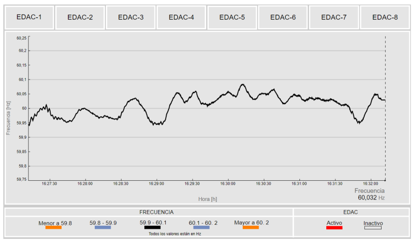
  • Real-time frequency monitoring, including alarms of the load shedding scheme.
  • Real-time RoCoF monitoring.
  • Real-time monitoring of angle differences between operational areas.
  • Real-time detection and assessment of oscillations.
  • Real-time monitoring of the voltage profile.
The sampling rate for all PMUs in Colombia is ten samples per s. Both the high-speed historian system and the analytics models that process this information operate with each change in the signals. This allows for real-time monitoring at the same rate as the PMU measurements.
The data flow from the WAMS real-time applications to the displays in the control center follows the architecture shown in Figure 5. Centralization on big data platforms enhances the access, processing, and presentation of data in deployments with situational awareness functionalities.
Note: The visualizations and data presented to explain each of the following applications were captured during the actual operation of the Colombian electrical system. They reflect the colorimetry conditions and alerts that were active at the time, providing a clear demonstration of the applications currently in use in the control room.

5.1. Real-Time Frequency Monitoring

Balancing load and generation is one of the primary objectives in power system operations. Active power imbalances, caused by generator disconnections, load variations, or exchange variations, lead to fluctuations in the electrical frequency of a power system. These imbalances are corrected by control mechanisms that operate at different response times, such as primary, sary, and tertiary frequency regulation.
This application enables the real-time monitoring of the frequency behavior of the Colombian electrical system using measurements from PMUs, which are displayed in the control room.
The display consists of two main segments. The first segment shows the real-time behavior of the system frequency, the values that define the operating ranges, and the alarm specifications triggered when these limits are exceeded. The s upper segment displays visual indicators for the activation of the eight stages of the underfrequency load shedding (UFLS) scheme.
The application references specific PMUs within the network and continuously evaluates the quality of the measurements. If a PMU provides poor-quality data, another frequency measurement is automatically selected from a priority list. The data analysis model for this application includes at least two PMUs for each operational area to monitor the frequency in all areas of the Colombian system.
Given the importance of situational awareness for operators, the application dynamically changes to alert operators of abnormal or transient behavior outside of typical operating limits. The reference frequency of the electrical system is 60.0 Hz, represented in the graph with a dark gray color. When the frequency exceeds the upper limit of 60.10 Hz or falls below the lower limit of 59.90 Hz, the frequency signal turns orange, indicating a warning. Warning limits are displayed on the graph with two dark gray lines. If the frequency remains in this state for 12 s, the maximum frequency reached and the duration outside these limits are displayed on the graph. Similarly, when the frequency exceeds the upper limit of 60.20 Hz or falls below the lower limit of 59.80 Hz, the frequency signal turns red, indicating an alert, and immediately displays the maximum frequency reached and the duration outside these limits.
Regarding the activation signaling of the UFLS stages, the logic of the UFLS stages approved in the Colombian system for 2023–2024 [53] is included in the real-time analysis model and is shown in Table 3.
Figure 6 shows the real-time frequency display of the Colombian system between 16:27 and 16:32 (5 min). For better understanding of Figure 6, which is in Spanish and is the original presented in the control room, the meanings of the main words used are provided below. ’Frecuencia’ means frequency, ’EDAC’ means UFLS, ’Activo’ means active, ’Inactivo’ means inactive, ’Mayor a’ means ’Greater than’ and ’Menor a’ means ’Less than’.
In practice, this application for monitoring frequency and the UFLS scheme is used to define real-time frequency regulation needs in the grid. This ensures that in the event of frequency changes, the system recovers adequately through automatic controls such as primary and sary frequency regulation. Additionally, real-time actions are implemented, such as managing commands to increase the power of generation units or disconnecting loads in cases of underfrequency and sending active power commands to reduce generation in cases of overfrequency.
Furthermore, the creation of underfrequency and overfrequency events in the analytics platform triggers the analysis of the effective performance of primary frequency regulation, using the method presented in [54].

5.2. Real-Time Rate of Change of Frequency (RoCoF) Monitoring

In recent years, the integration of various nonconventional renewable generation technologies into electrical systems has introduced new operational challenges due to the reduction in inertia and network strength. This can impact system stability, particularly frequency stability, and cause significant frequency deviations during disturbances. Therefore, it is necessary to monitor the evolution of frequency stability and indicators that characterize each network event that produces considerable deviations from the nominal frequency.
From this perspective, several performance indicators are found to be very useful for many power system monitoring and control functions, such as the RoCoF and nadir/zenith (minimum/maximum value of frequency during an event). Recently, in [49], a methodology was proposed to compute frequency stability performance indicators using synchrophasor measurements in an offline approach for the Colombian power system, aiming at the characterization and postoperative analysis of large disturbances. However, there is a need to monitor the RoCoF in real time due to the increase in low-inertia generation technology, which impacts the robustness of the power system.
The real-time monitoring and evaluation of the RoCoF were developed with the following characteristics:
  • Monitoring at least one frequency for each operational area (in Colombia, there are five operational areas defined).
  • The implementation of redundancy for the frequency measurement of the reference PMU in case of quality problems with the main PMU.
  • RoCoF calculation using Equation (1) with moving windows of Δ t = 500 ms (this value is configurable in the model), calculated at the PMU sampling rate (calculation every 100 ms in this case).
    RoCoF = F ( t ) F ( t Δ t ) Δ t
  • Calculation of the standard deviation of the RoCoF from the values of all operational areas.
  • Alert and storage of RoCoF events when the RoCoF of any PMU in an operational area meets any of these conditions:
    • Positive high RoCoF event: When the RoCoF is greater than the upper limit (0.5 Hz/s). The event must store the event start timestamp, the event end timestamp, the maximum positive RoCoF reached, and the name of the PMU (data source).
    • Negative high RoCoF event: When the RoCoF is less than the lower limit (−0.5 Hz/s). The event must store the event start timestamp, event end timestamp, the minimum frequency reached, and the name of the PMU (data source).
Based on the characteristics of the above model, a real-time monitoring display was implemented that includes two visual spaces. The first, on the left, shows real-time RoCoF monitoring, and the s, on the right, displays the frequency stability region.
  • RoCoF Monitoring: The graph with the RoCoF information of the power system is located on the left side of the display. The maximum limit is set to the greater of 0.1 Hz/s or the maximum value reached by the plotted curve. The minimum limit is set to the lesser of −0.1 Hz/s or the minimum value reached by the plotted curve.
    • The RoCoF reference of the electrical system is 0 Hz/s, represented in the graph by a dark gray line. If the upper limit of 0.1 Hz/s or the lower limit of −0.1 Hz/s is exceeded for more than 5 s, the frequency signal will turn blue to indicate warning. These limits are represented in the graph by two dark gray lines. Additionally, the maximum/minimum RoCoF values reached and the duration outside these limits will be displayed on the graph.
    • When the upper limit of 0.5 Hz/s or the lower limit of −0.5 Hz/s is exceeded, the frequency signal will turn orange, indicating an alert. The maximum RoCoF reached and the duration outside these limits will be displayed immediately. These limits are represented in the graph by two dark gray lines.
  • Frequency Stability Security Region: On the right side of the display, a security region view shows the trajectory of the frequency and RoCoF. If the lower limit of −0.5 Hz/s or the lower frequency limit of 59.4 Hz is exceeded, the signal will turn orange, indicating an alert. The maximum negative RoCoF reached, the minimum frequency reached (nadir), and the duration outside these limits will be displayed immediately.
An example of this display can be seen in Figure 7. It is designed with dynamic changes in colors and scales to alert the operator when established limits are exceeded. In this example, RoCoF monitoring is presented during a generation disconnection event causing a transient underfrequency. In real-time monitoring of RoCoF, it is observed that for this underfrequency event, the RoCoF does not reach the warning threshold of −0.1 Hz/s. The security region graph shows the trajectory of the power system from the precontingency condition (state marked with number 1) to the postcontingency condition (state marked with number 2). Status 2 and a diamond within the real-time display represent the current or last value of the time series.
Considering this new tool for monitoring the RoCoF, the results from both real-time visualizations and historical data analysis of the actual RoCoF significantly enhance decision-making processes aimed at improving dynamic performance and mitigating the challenges posed by inertia reduction across various operational horizons.
  • Real-time Operation: Synchronize generation units, synchronous condensers, or connect inverter-based resources with grid-forming technology that provides inertial effects, taking into account current operating conditions.
  • Short-term (Weekly) and Very Short-term (Daily) Operation Planning: Implement security restrictions in energy dispatch to integrate generation units or other technologies into operation under low-inertia conditions.
  • Medium-term Planning (1–12 months): Identify the generation units with the greatest impact on inertia and the RoCoF to provide real-time operational recommendations.
  • Long-term Planning (>1 year): Identify new technological needs for integration into the electrical grid to improve inertia and grid performance. Notable technological solutions include control strategies for grid-forming inverter-based resource converters and synchronous condensers.
For the Colombian electrical system, the national entity responsible for grid expansion planning published the master plan for grid modernization and expansion in [55]. This plan includes the implementation of battery energy storage systems (BESSs) with grid-forming technology in five substations for various applications, such as improving inertia. Additionally, the plan outlines the installation of 15 synchronous condensers to enhance inertia, grid strength, and other functionalities.
Furthermore, the modernization master plan emphasizes the importance of synchronized phasor measurements, which are crucial for the energy transition. It also highlights the development of new tools for monitoring RoCoF and inertia, among other applications, to effectively track the network dynamics with the integration of inverter-based resources.

5.3. Real-Time Angle Monitoring

The angular difference of bus voltages in an electrical power system is a direct measure of the state of congestion in the system. Continuous monitoring of these differences provides operators with warning signals of potential congestion when angular differences exceed pre-established safety limits (static angle stability limits).
To maintain the security and efficiency of electrical power systems, real-time monitoring of angular differences between operating areas is crucial. Some of its applications include the following:
  • System Stability: Angular differences between busbars in a power system are direct indicators of the system’s stability status. If these differences exceed certain limits, it can indicate possible instability or congestion in the system, affecting the maximum power transfer and its relation to the angular difference.
  • Fault Prevention: Monitoring these differences allows for the detection and mitigation of potential problems before they escalate into serious faults. This is especially important in interconnected systems, where a failure in one part can impact the entire system.
  • Energy Dispatch Optimization: Real-time knowledge of angular differences helps optimize energy flow, ensuring that the resources of the National Interconnected System are dispatched efficiently and safely.
  • Early Warnings: Implementing real-time monitoring systems enables early warnings, helping operators make informed and quick decisions to maintain system stability.
For monitoring angular differences, PMU-supervised voltage angle information is used. This development includes the following features: On the left side, there is a phasor radar-type diagram indicating the angular difference between a designated PMU for each subarea and a reference for the whole country, selected from a prioritized list in the developed analytics model. On the right side, a map of the country is displayed with six spheres, five corresponding to the Caribbean, Antioquia, Northeast, Southwest, and East regions and a sixth representing the exchange with Ecuador. Here, the angular differences measured in each of these sub-areas are calculated.
The display incorporates dynamic changes that represent the direction of power flow according to the sign of the angular difference and color changes when different warning and alert limits are exceeded, as shown in the lower-left legend of Figure 8. For better understanding of Figure 8, which is in Spanish and is the original presented in the control room, the meanings of the main words used are provided below. ’Referencia’ means reference, ’Sentido Flujo’ means flow direction and “No hay dato” means no data.

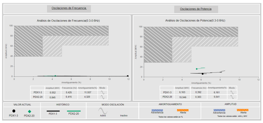
5.4. Real-Time Detection and Assessment of Oscillations

Interconnected power systems comprise significant rotating masses interconnected via an electrical network. Perturbations within the system induce a variety of oscillations among the grid components. Typically, these oscillations are alleviated by inherent damping forces and active damping strategies. Nevertheless, there are instances where oscillations may lack sufficient damping or exhibit negative damping, leading to either sustained oscillations or those that amplify over time. Active controllers, such as automatic voltage regulators (AVRs) and turbine governor controllers, can sometimes aggravate inadequate or negative damping. Upon encountering a minor disturbance, the power system may exhibit the response types illustrated in Figure 9.
To sustain the integrity of the power system, it is imperative that all modes consistently exhibit positive damping. To ensure this condition persists even in the event of unanticipated occurrences, it is prudent to maintain a stability margin. Consequently, the system should seldom approach states that are close to undamped or negatively damped conditions.
To understand the current status of the power system in relation to oscillations, an oscillation management tool was implemented as part of the PhasorPoint WorkBench suite version 8.6-6. This tool allows for real-time acquisition of the oscillation modes, amplitude, and damping of each mode. The results of this analysis are sent to the BigData system of the PI suite through the IEC 60870-5-104 protocol to be displayed to the control room operator. This application identifies oscillatory phenomena in four different frequency modes previously identified as those that occur most frequently in the Colombian electrical system. The oscillation modes analyzed are as follows:
  • Low frequency [0.04–0.1 Hz].
  • Inter-area [0.1–0.3 Hz].
  • Colombia–Ecuador [0.3–0.6 Hz].
  • Other Mode [0.6–2.0 Hz].
Each oscillation mode is monitored in real time and presented in visualizations that analyze the oscillations of variable frequency and active power exchange between Colombia and Ecuador. An example of monitoring frequency oscillations and binational exchange power for the Colombia–Ecuador oscillation mode [0.3–0.6 Hz] is shown in Figure 10. The figure shows that each oscillation analysis display has light gray (warning) and dark gray (alert) shaded regions according to damping and oscillation amplitude values. When an oscillation enters one of these regions, it changes color to blue for the warning region and orange for the alert region. Additionally, the tool is equipped with the oscillation analysis results of two algorithms using different analysis window sizes: PDX1-3 (black trajectory) has a data window of 3 min and an update rate of the analysis result of 5 s, and PDX2-20 (green trajectory) has a data window of 20 min and an update rate of 20 s.
For better understanding of Figure 10, which is in Spanish and is the original presented in the control room, the meanings of the main words used are provided below. ’Oscilación’ means oscillation, ’Potencia’ means active power, ’Amplitud’ means amplitude, ’Amortiguamiento’ means damping, ’Histórico’ means historian, ’Modo’ means mode, ’Advertencia’ means warning, and ’Alerta’ means alert.
This application provides three clear value-added approaches for the operation of the interconnected system:
  • Real-time operation: Assists in detecting oscillations and mitigating them through the implementation of pre-established actions, such as reducing the generation of certain units previously identified as contributors to these oscillations.
  • Postoperative analysis: Detects and evaluates oscillations, identifying units considered sources of oscillation to integrate them into a power system stabilizer (PSS) tuning procedure. This process determines the optimal control parameters to dampen oscillations within a specific frequency band.
  • Frequency range detection: Identifies oscillations in different frequency ranges, determines the cause through postoperative analysis, and finds mitigation methods. These methods may include control adjustments, the integration of new performance requirements for generation units, or new procedures to mitigate oscillations that can be applied in real-time operation.

5.5. Real-Time Voltage Profile Monitoring

Monitoring and controlling the magnitude of the voltage is one of the main objectives of power system operation. Although SCADA systems have allowed for the monitoring of node voltages in an interconnected system, the integration of PMUs has introduced several applications, including their use as a backup to traditional measurements. A more specific application of direct monitoring is the evaluation of dynamic phenomena and the validation of compliance with transient voltage recovery requirements established in network codes. In particular, in the Colombian system, regulations require that voltages not be below 0.8 p.u. for more than 500 ms. This requirement was recently implemented for an offline postoperative evaluation with PMU measurements, as detailed in [48]. However, real-time monitoring is also required to take actions to reduce vulnerabilities, particularly short-term voltage stability phenomena such as fault-induced delayed voltage recovery (FIDVR) or fast voltage collapse.
For monitoring steady-state voltage and during transients, a display was implemented to show the operator abnormal voltage conditions.
1.
Definition of limits by regulation or network code and historical limits according to the averages and standard deviations of each node monitored with PMU. The defined limits are as follows:
(a)
HiRegulatory: Regulatory upper limit, 1.05 for 500 kV busbars and 1.1 for busbars below 500 kV.
(b)
Hi1 and Hi2: First and s historical upper limits.
(c)
Lo1 and Lo2: First and s historical lower limits.
(d)
LoRegulatory: Regulatory lower limit, 0.9 for all busbars.
(e)
LoTransient: Regulatory transient voltage recovery limit, 0.8 for all busbars, including a 500 ms time limit.
2.
For the voltage variables configured by the substation in phases a, b, and c, the following calculations are performed:
(a)
Calculate the p.u. values of the variables, taking into account their nominal voltage.
(b)
Calculate the time that each voltage remains below the LoTransient limit of 0.8 p.u.
3.
Storage of events that do not comply with regulatory limits:
(a)
FIDVR event: When the transient voltage recovery remains below 0.8 p.u. for more than 500 ms. The event must store the event start timestamp, event end timestamp, recovery time, minimum voltage value reached, the substation/bar where it occurred, and the phase (phase a, phase b, phase c). Cases in which the voltage falls below 0.1 p.u. are excluded, as they represent element disconnections.
(b)
Undervoltage Event: When the voltage is lower than the LoRegulatory limit for more than 1 min. Exclude cases where the voltage is below 0.1 p.u., as they represent disconnections of elements. The event must store the event start timestamp, event end timestamp, recovery time, minimum voltage value reached, the substation/bar where it occurred, and the phase (phase a, phase b, phase c).
(c)
Overvoltage Event: When the voltage is higher than the HiRegulatory limit for more than 1 min. The event must store the event start timestamp, event end timestamp, recovery time, maximum voltage value reached, the substation/bar where it occurred, and the phase (phase a, phase b, phase c).
With the above characteristics, a display was developed for real-time monitoring that considers the voltage profile with historical and regulatory limits, as shown in Figure 11. The left side shows horizontal bars that are displayed only when the voltage value exceeds a statistical limit or when it is close to the regulatory limits: below 0.92 p.u., above 1.04 p.u. for busbars with rated voltage equal to 500 kV, and above 1.08 p.u. for busbars with lower rated voltage. On the right is the Colombian map with the location of the PMUs, with color changes according to the voltage dynamics and the size of the circles indicating the voltage level. For better understanding of Figure 11, which is in Spanish and is the original presented in the control room, the meanings of the main words used are provided below. ’Tendencia’ means trend, ’Alta Tensión’ means high voltage, and ’Baja Tensión’ means low voltage.
This voltage-monitoring application allows the operator to understand the status of the system in real time and take voltage control actions based on whether the issue is static (voltage profiles) or dynamic (voltage recovery issues or FIDVR). For static issues, the operator can adjust transformer taps, connect or disconnect capacitors or reactors, and change the setpoints of automatic voltage regulators on generators. For dynamic issues, it is necessary to increase the reactive reserves of the equipment capable of providing dynamic reactive power to control voltage. Some options include synchronizing generation units, connecting reactive power compensators (SVC or STATCOM), connecting synchronous condensers, and integrating inverter-based resources (solar, wind, storage) with voltage control and fault-ride-through capabilities.

6. Perspectives of Synchrophasor Applications

Considering technological changes in the integration of inverter-based resources (IBRs) into the generation and control of the grid, a change in the dynamic behavior of the grid is expected in the face of disturbances. This necessitates new efforts in developing applications for the real-time monitoring and evaluation of various grid phenomena, including the following.
  • Monitoring and Evaluation of Network Strength: Operation planning studies by the NDC in Colombia highlight the importance of network strength with IBR integration, as it presents a risk of instability during large disturbances. Metrics such as the short-circuit ratio (SCR) have been established to maintain stability; however, a methodology and real-time tool are required to evaluate network strength and support decision-making in real-time operations.
  • Real-Time Inertia Monitoring: The displacement of synchronous generation by inverter-based generation reduces the system’s robustness to remain stable during events and active power imbalances. This requires both the RoCoF monitoring proposed in this article and real-time inertia monitoring for operational decision-making.
  • Long-Term Voltage Stability Monitoring: Transmission grids are operating closer to stability limits due to delays in infrastructure expansion or environmental challenges. Maintaining grid security requires real-time monitoring of voltage stability before and after disturbances, which is achievable with PMU-based algorithms.
  • Voltage Sag Propagation Monitoring: The Colombian power grid is vulnerable to phenomena such as FIDVR, which post-operational studies have shown can propagate voltage sags affecting sensitive loads such as electronic devices and induction motors, potentially causing inverter-based generator disconnections. Real-time tools are needed to assess the impact and propagation of voltage sags during network disturbances.

7. Conclusions

This paper presents the development and implementation of five applications for monitoring various network dynamics, including voltage stability, angle stability, and frequency stability. A novel real-time RoCoF monitoring application was introduced, demonstrating its behavior under normal conditions and during generator disconnection events. Continuous RoCoF monitoring is crucial for power systems with increased inverter-based generation.
The architecture of the Colombian WAMS was detailed, highlighting the integration of high-speed big data platforms. These platforms provide customizable tools, easy data access, and integration with other data sources such as SCADA data from RTUs, allowing the creation of new hybrid applications. The technological evolution of the WAMS network for real-time monitoring and the new approach to integrated high-speed data analytics to process various information sources and high-sampling-rate data were highlighted.
The developed real-time dynamics monitoring tools feature innovative aspects such as data quality analysis, data redundancy to enhance reliability and availability, and dynamically changing color displays and alerts to improve situational awareness for control room operators. These tools include new visualizations and analytics models for real-time monitoring of frequency, rate of change of frequency (RoCoF), angular differences, oscillations, and voltage transient recovery and profile based on industry criteria to monitor different phenomena.

Author Contributions

Investigation and conceptualization, S.B. and J.D.P.; original draft preparation, S.B., J.D.P., and D.G.-G.; review and editing, J.D.P. All authors have read and agreed to the published version of the manuscript.

Funding

This research received no external funding.

Institutional Review Board Statement

Not applicable.

Informed Consent Statement

Not applicable.

Data Availability Statement

Data are contained within the article.

Conflicts of Interest

Authors Samuel Bustamante, Jaime D. Pinzón and Daniel Giraldo-Gómez were employed by the company XM S.A. E.S.P. The authors declare that the research was conducted in the absence of any commercial or financial relationships that could be construed as a potential conflict of interest.

Abbreviations

The following abbreviations are used in this manuscript:
WAMSWide-Area Monitoring System
PMUPhasor Measurement Unit
MPLSMultiprotocol label switch
PDCPhasor Data Concentrator
EPSElectrical power system
NDCNational Dispatch Center
NTSNational Transmission System
NOCNational Operational Council
SCADASupervisory Control and Data Acquisition
RTURemote Terminal Unit
EMTElectromagnetic Transients
ESAArea Separation Scheme
FIDVRFault-Induced Delayed Voltage Recovery
RoCoFRate of change of frequency
DAData Archive
AFAsset Framework
UFLSUnderfrequency Load Shedding
PSSPower System Stabilizer
SCRShort-Circuit Ratio

References

  1. Denholm, P.; Mai, T.; Kenyon, R.W.; Kroposki, B.; O’Malley, M. Inertia and the Power Grid: A Guide Without the Spin; Technical Report; National Renewable Energy Laboratory (NREL): Golden, CO, USA, 2020. [Google Scholar]
  2. Akrami, A.; Doostizadeh, M.; Aminifar, F. Power system flexibility: An overview of emergence to evolution. J. Mod. Power Syst. Clean Energy 2019, 7, 987–1007. [Google Scholar] [CrossRef]
  3. Maheswari, M.; Suthanthira Vanitha, N.; Loganathan, N. Wide-Area Measurement Systems and Phasor Measurement Units. In Wide Area Power Systems Stability, Protection, and Security; Haes Alhelou, H., Abdelaziz, A.Y., Siano, P., Eds.; Springer International Publishing: Cham, Switzerland, 2021; pp. 105–126. [Google Scholar]
  4. Pinzón, J.D. Evaluación de la Estabilidad de Tensión de Corto Plazo de los Sistemas Eléctricos de Potencia en Tiempo Real. Ph.D. Thesis, Universidad Nacional de San Juan, San Juan, Argentina, 2019. [Google Scholar]
  5. Zhang, F.; Cheng, L.; Gao, W.; Huang, R. Synchrophasors-Based Identification for Subsynchronous Oscillations in Power Systems. IEEE Trans. Smart Grid 2019, 10, 2224–2233. [Google Scholar] [CrossRef]
  6. Negi, S.S.; Kishor, N.; Singh, A. PMUs data based detection of oscillatory events and identification of their associated variable: Estimation of information measures approach. Sustain. Energy, Grids Netw. 2024, 39, 101457. [Google Scholar] [CrossRef]
  7. Zamani, R.; Panahi, H.; Abyaz, A.; Haes Alhelou, H. Introduction to WAMS and Its Applications for Future Power System. In Wide Area Power Systems Stability, Protection, and Security; Haes Alhelou, H., Abdelaziz, A.Y., Siano, P., Eds.; Springer International Publishing: Cham, Switzerland, 2021; pp. 45–69. [Google Scholar] [CrossRef]
  8. Phadke, A.G.; Thorp, J.S. Synchronized Phasor Measurements and Their Applications; Springer: Berlin/Heidelberg, Germany, 2008; Volume 1. [Google Scholar]
  9. Narayanan, K.S.; Sudhir, R.; Kanna, Y. WAMS—Mitigating Angular Instability in Large Interconnected Power Systems. In Proceedings of the 2015 Saudi Arabia Smart Grid (SASG), Jeddah, Saudi Arabia, 7–9 December 2015; pp. 1–5. [Google Scholar]
  10. Acosta, M.N.; Gómez, E.; Gonzalez-Longatt, F.; Andrade, M.A.; Vázquez, E.; Barocio, E. Single Value Decomposition to Estimate Critical Clearing Time of a Power System Using Measurements. IEEE Access 2021, 9, 125999–126010. [Google Scholar] [CrossRef]
  11. Chrashekhar, P.K.; Srivani, S.G. Wide Area Based Online Transient Stability Prediction Using Regression Model. In Proceedings of the 2022 IEEE 7th International Conference on Recent Advances and Innovations in Engineering (ICRAIE), Mangalore, India, 1–3 December 2022; Volume 7, pp. 433–437. [Google Scholar]
  12. Hosseini, H.; Naderi, S.; Afsharnia, S. New approach to transient stability prediction of power systems in wide area measurement systems based on multiple-criteria decision making theory. IET Gener. Transm. Distrib. 2019, 13, 4960–4967. [Google Scholar] [CrossRef]
  13. Zhou, H.Z.; Tang, F.; Jia, J.; Ye, X.L. The Transient Stability Analysis Based on WAMS and Online Admittance Parameter Identification. In Proceedings of the 2015 IEEE Eindhoven PowerTech, Eindhoven, The Netherlands, 29 June–2 July 2015; pp. 1–6. [Google Scholar]
  14. Pinzón, J.D.; Colomé, D.G. PMU-based Online Monitoring of Short-term Voltage Stability using Lyapunov Exponents. IEEE Lat. Am. Trans. 2019, 17, 1578–1587. [Google Scholar] [CrossRef]
  15. Zhu, L.; Lu, C.; Kamwa, I.; Zeng, H. Spatial–Temporal Feature Learning in Smart Grids: A Case Study on Short-Term Voltage Stability Assessment. IEEE Trans. Ind. Inform. 2020, 16, 1470–1482. [Google Scholar] [CrossRef]
  16. Pinzón, J.D.; Colomé, D.G. Real-time multi-state classification of short-term voltage stability based on multivariate time series machine learning. Int. J. Electr. Power Energy Syst. 2019, 108, 402–414. [Google Scholar] [CrossRef]
  17. Yun, Z.; Cui, X.; Ma, K. Online Thevenin Equivalent Parameter Identification Method of Large Power Grids Using LU Factorization. IEEE Trans. Power Syst. 2019, 34, 4464–4475. [Google Scholar] [CrossRef]
  18. Pinzón, J.D.; Colomé, D.G. Voltage Stability Assessment Using Synchrophasor Measurements: Trends and Development. In Proceedings of the 2017 IEEE PES Innovative Smart Grid Technologies Conference-Latin America (ISGT Latin America), Quito, Ecuador, 20–22 September 2017; pp. 1–6. [Google Scholar] [CrossRef]
  19. Li, Y.; Cao, J.; Xu, Y.; Zhu, L.; Dong, Z.Y. Deep learning based on Transformer architecture for power system short-term voltage stability assessment with class imbalance. Renew. Sustain. Energy Rev. 2024, 189, 113913. [Google Scholar] [CrossRef]
  20. Pinzón, J.D.; Colomé, D.G. Data Analytics of PMU Measurement Features for Real-time Short-term Voltage Stability Prediction. In Proceedings of the 2019 FISE-IEEE/CIGRE Conference-Living the Energy Transition (FISE/CIGRE), Medellin, Colombia, 4–6 December 2019; pp. 1–6. [Google Scholar] [CrossRef]
  21. Liu, S.; Zhao, Y.; Lin, Z.; Liu, Y.; Ding, Y.; Yang, L.; Yi, S. Data-Driven Event Detection of Power Systems Based on Unequal-Interval Reduction of PMU Data and Local Outlier Factor. IEEE Trans. Smart Grid 2020, 11, 1630–1643. [Google Scholar] [CrossRef]
  22. Shaw, P.; Kumar Jena, M. A Novel Event Detection and Classification Scheme Using Wide-Area Frequency Measurements. IEEE Trans. Smart Grid 2021, 12, 2320–2330. [Google Scholar] [CrossRef]
  23. Lopes, G.V.d.S.; Moraes, G.R.; Issicaba, D.; Dotta, D. WAMS-based two-level robust detection methodology of power system events. Sustain. Energy, Grids Netw. 2022, 31, 100689. [Google Scholar] [CrossRef]
  24. Abedi, M.; Aghamohammadi, M.R.; Azad, S.; Nazari-Heris, M.; Asadi, S. Prediction of Out-of-Step Condition for Synchronous Generators Using Decision Tree Based on the Dynamic Data by WAMS/PMU. In Application of Machine Learning and Deep Learning Methods to Power System Problems; Nazari-Heris, M., Asadi, S., Mohammadi-Ivatloo, B., Abdar, M., Jebelli, H., Sadat-Mohammadi, M., Eds.; Springer International Publishing: Cham, Switzerland, 2021; pp. 289–319. [Google Scholar] [CrossRef]
  25. da Silva, D.S.; Moraes, G.R.; Penna, L.D.; Decker, I.C.; Aquino, A.F.; Issicaba, D. Monitoring systemic dynamic effects following disturbances affecting HVDC power transmission in the BIPS using WAMS infrastructure. Electr. Power Syst. Res. 2024, 235, 110821. [Google Scholar] [CrossRef]
  26. Panda, R.K.; Mohapatra, A.; Srivastava, S.C. Online estimation of system inertia in a power network utilizing synchrophasor measurements. IEEE Trans. Power Syst. 2019, 35, 3122–3132. [Google Scholar] [CrossRef]
  27. Mahto, D.K.; Kibriya, F.; Khalkho, A.M.; Mohanta, D.K. Data Driven Approach for Wide Area Generator Coherency Detection Using Synchrophasor Measurements. In Proceedings of the 2019 IEEE Region 10 Symposium (TENSYMP), Kolkata, India, 7–9 June 2019; pp. 771–774. [Google Scholar]
  28. Lakshmanan, L.; Swarup, K. Inertia monitoring in power systems: Critical features, challenges, and framework. Renew. Sustain. Energy Rev. 2024, 190, 114076. [Google Scholar] [CrossRef]
  29. Ashton, P.M.; Saunders, C.S.; Taylor, G.A.; Carter, A.M.; Bradley, M.E. Inertia Estimation of the GB Power System Using Synchrophasor Measurements. IEEE Trans. Power Syst. 2015, 30, 701–709. [Google Scholar] [CrossRef]
  30. Kerdphol, T.; Watanabe, M.; Mitani, Y.; Ngamroo, I. Inertia Assessment From Transient Measurements: Recent Perspective From Japanese WAMS. IEEE Access 2022, 10, 66332–66344. [Google Scholar] [CrossRef]
  31. Fu, X.; Xu, X. The research on wide-area protection technology in power systems supported by wide-area measurement systems. Adv. Resour. Res. 2025, 5, 103–122. [Google Scholar] [CrossRef]
  32. Cepeda, J.C.; Echeverría, D.E.; Chamba, M.S.; Kamwa, I.; Rueda-Torres, J. Wide-Area Monitoring Protection and Control Supported Operation and Planning in the Ecuadorian Power System: Improving Security and Reliability. IEEE Power Energy Mag. 2025, 23, 59–68. [Google Scholar] [CrossRef]
  33. Chintakindi, R.; Mitra, A. Execution of Real-time Wide Area Monitoring System with Big Data Functions and Practices. In Proceedings of the 2020 IEEE 9th Power India International Conference (PIICON), Sonepat, India, 28 February–1 March 2020; pp. 1–6. [Google Scholar] [CrossRef]
  34. Katariya, K.V.; Yadav, R.; Kumar, S.; Pradhan, A.K.; Kamwa, I. Wide-Area-Measurement-System-Based Event Analytics in the Power System: A Data-Driven Framework for Disturbance Characterization and Source Localization in the Indian Grid. IEEE Power Energy Mag. 2025, 23, 35–46. [Google Scholar] [CrossRef]
  35. Chintakindi, R.; Mitra, A. WAMS challenges and limitations in load modeling, voltage stability improvement, and controlled island protection—A review. Energy Rep. 2022, 8, 699–709. [Google Scholar] [CrossRef]
  36. Hart, P.; He, L.; Wang, T.; Kumar, V.S.; Aggour, K.; Subramanian, A.; Yan, W. Application of Big Data Analytics and Machine Learning to Large-Scale Synchrophasor Datasets: Evaluation of Dataset ‘Machine Learning-Readiness’. IEEE Open Access J. Power Energy 2022, 9, 386–397. [Google Scholar] [CrossRef]
  37. Sattinger, W.; Hillberg, E.; Kezunovic, M. Wide Area Monitoring Protection and Control Systems–Decision Support for System Operators; CIGRE: Paris, France, 2023. [Google Scholar]
  38. Ortiz, G.; Rehtanz, C.; Colomé, G. Monitoring of power system dynamics under incomplete PMU observability condition. IET Gener. Transm. Distrib. 2021, 15, 1435–1450. [Google Scholar] [CrossRef]
  39. Cheng, G.; Lin, Y.; Abur, A.; Gómez-Expósito, A.; Wu, W. A survey of power system state estimation using multiple data sources: PMUs, SCADA, AMI, and beyond. IEEE Trans. Smart Grid 2023, 15, 1129–1151. [Google Scholar] [CrossRef]
  40. Zhao, L.; Huang, L.; Lv, Q.; Yang, T.; Wei, D. WAMS/SCADA Data Fusion Method Study Based on Time-Series Data Correlation Mining. In Proceedings of the Advances in Artificial Systems for Medicine and Education, Moscow, Russia, 21–23 August 2017; Springer: Berlin/Heidelberg, Germany, 2018; pp. 120–133. [Google Scholar]
  41. Leon, R.; Gomez, J. Colombian National Defense System Against Large Scale Events. In Proceedings of the 2011 IEEE Power and Energy Society General Meeting, Detroit, MI, USA, 24–28 July 2011; pp. 1–6. [Google Scholar]
  42. Cimadevilla, R. Fundamentos de la Medición de Sincrofasores. XIII ERIAC 2009, 1. [Google Scholar]
  43. Arango, O.; Sanchez, H.; Wilson, D. Low Frequency Oscillations in the Colombian Power System. In Identification and Remedial Actions; CIGRE: Paris, France, 2010; pp. 2–105. [Google Scholar]
  44. Myrda, P.T.; Koellner, K. NASPInet-The Internet for Synchrophasors. In Proceedings of the 2010 43rd Hawaii International Conference on System Sciences, Honolulu, HI, USA, 5–8 January 2010; pp. 1–6. [Google Scholar] [CrossRef]
  45. Giraldo-Gómez, D.; Arboleda, B.; Viana-Villa, P.; Quintero-Zuluaga, F.; Villegas, D.; Sánchez, M.; Tóbon, Á.; Gómez, J.; Duque, N. Towards a Colombian Power System Fully Supervised with PMU: Scalability Test of the iSAACnet Communications Network. In Proceedings of the 2020 IEEE PES Transmission & Distribution Conference and Exhibition-Latin America (T&D LA), Montevideo, Uruguay, 28 September–2 October 2020; pp. 1–6. [Google Scholar] [CrossRef]
  46. Giraldo, M.; Espinosa Oviedo, J.; Valencia, F.; Cifuentes, M.; Perez, E.; Salazar, S.; Amador, W.; Ortiz, N.; Tobon, J. Hierarchical and Distributed State Estimation for Power Systems: The Colombia Case; CIGRE: Paris, France, 2014. [Google Scholar]
  47. Quintero-Zuluaga, F.; Viana-Villa, P.; Giraldo-Gómez, D.; Arboleda, B.; Villegas, D.; Sánchez, M.; Pérez, C.; Duque, N. Hardware in the Loop Design and Testing of a PMU-Based Special Protection Scheme: Case Study of Colombia-Ecuador Interconnection. In Proceedings of the 2020 IEEE PES Transmission & Distribution Conference and Exhibition-Latin America (T&D LA), Montevideo, Uruguay, 28 September–2 October 2020; pp. 1–6. [Google Scholar] [CrossRef]
  48. Pinzón, J.D.; Santamaria, F.; Espinel, A. Fault-Induced Delayed Voltage Recovery Assessment in the Colombian Power System Using Synchrophasor Measurements. In Proceedings of the 2023 IEEE PES Innovative Smart Grid Technologies Latin America (ISGT-LA), San Juan, PR, USA, 6–9 November 2023; pp. 20–24. [Google Scholar] [CrossRef]
  49. Pinzón, J.D. Synchrophasor-based Tool for Computing Performance Indicators of Frequency Stability. In Proceedings of the 2024 IEEE PES Generation, Transmission and Distribution Latin America Conference (GTDLA24), Guerrero, México, 11–13 November 2024. [Google Scholar]
  50. Pinzón, J.D.; Santamaria, F.; Espinel, A. Parallel Computing-Based PMU Measurements Big Data Query Tool to Analyze the Colombian Power System Dynamic Performance. In Proceedings of the 2023 IEEE PES Innovative Smart Grid Technologies Latin America (ISGT-LA), San Juan, PR, USA, 6–9 November 2023; pp. 25–29. [Google Scholar] [CrossRef]
  51. IEEE Standard C37. 118.2-2024; IEEE Standard for Synchrophasor Data Transfer for Power Systems. IEEE: Piscataway, NJ, USA, 2024; Available online: https://standards.ieee.org/ieee/C37.118.2/7077/ (accessed on 1 December 2024).
  52. IEC Standard 60870-5-104; Telecontrol Equipment and Systems–Part 5-104: Transmission Protocols–Network Access for IEC 60870-5-101 Using Standard Transport Profiles. International Electrotechnical Commission: Geneva, Switzerland, 2006. Available online: https://webstore.iec.ch/publication/3746 (accessed on 1 December 2024).
  53. Consejo Nacional de Operación. Acuerdo 1659 Por el Cual se Aprueba el Esquema de Deslastre Automático de Carga EDAC por Baja Frecuencia para el Año 2023. 2023. Available online: https://www.cno.org.co/content/acuerdo-1659-por-el-cual-se-aprueba-el-esquema-de-deslastre-automatico-de-carga-edac-por (accessed on 1 December 2024).
  54. Meza, V.M.; Perez, B.; Pinzón, J.D. Metodología para Automatizar la Evaluación del Desempeño de la Respuesta Primaria de Frecuencia de Generadores. In Proceedings of the XIX Encontro Regional Ibero-Americano do CIGRE-ERIAC, Foz do Iguaçu, Brazil, 21–25 May 2023; CIGRE: Paris, France, 2023. [Google Scholar]
  55. Unidad de Planeación Minero Energética. Plan Maestro de Modernización y Expansión de la Infraestructura de Transmisión Eléctrica; UPME: Bogotá, Colombia, 2024. [Google Scholar]
Figure 1. In-house manufactured PMU.
Sustainability 17 03848 g001
Figure 2. Percentage of EPS elements monitored with PMUs.
Sustainability 17 03848 g002
Figure 3. WAMS nodes and MPLS geographic distribution.
Sustainability 17 03848 g003
Figure 4. Data flows across synchrophasor applications in the NDC.
Sustainability 17 03848 g004
Figure 5. WAMS to PI system architecture.
Sustainability 17 03848 g005
Figure 6. Real–time frequency monitoring view.
Sustainability 17 03848 g006
Figure 7. Real-time RoCoF-monitoring view.
Sustainability 17 03848 g007
Figure 8. Real-time angle monitoring between areas.
Sustainability 17 03848 g008
Figure 9. Oscillation classification.
Sustainability 17 03848 g009
Figure 10. Real-time monitoring of oscillations.
Sustainability 17 03848 g010
Figure 11. Real-time voltage profile monitoring view.
Sustainability 17 03848 g011
Table 1. SCADA-WAMS comparison.
ParameterSCADA (Based on RTU)WAMS (Based on PMU)
Resolution1 sample every 2–4 s (steady-state observability)10–60 samples per s (dynamic observability)
Measured VariablesVoltage and current magnitudeVoltage and current magnitude and angle, in addition to frequency and df/dt
Time SynchronizationNoYes—GPS
Number of I/O Channels+100 analog and digital∼12 phasors
+16 digital, +16 analog
UsageLocal monitoring and controlWide-area monitoring and control
Application FunctionsEfficient and reliable algorithms, tested in real power systemsNeed to develop and test new algorithms
Total CostRelatively lowHigh
Table 2. Colombian real-time SCADA system and WAMS.
AttributeSCADAWAMS
Substations49025
Power plants3505
Communication channels14030
Num of signals [per sec.]27.0006000
Table 3. Colombian UFLS 2023-2024.
StageFrequency [Hz]Intentional Delay [ms]Load Shedding [%]Frequency [Hz] (Settings df/dt)]df/dt [Hz/s]Intentional Delay [ms] (Settings df/dt)
159.42005
259.22005
359.04005
458.84005
558.66005
658.610005
758.42000558−0.3200
858.44000558−0.2400
Disclaimer/Publisher’s Note: The statements, opinions and data contained in all publications are solely those of the individual author(s) and contributor(s) and not of MDPI and/or the editor(s). MDPI and/or the editor(s) disclaim responsibility for any injury to people or property resulting from any ideas, methods, instructions or products referred to in the content.

