


Abstract
The WELL Building Standard (WELL) is a certification system designed to enhance occupant health and well-being in indoor environments. Conventional building energy-saving strategies typically rely on fixed temperature setpoint adjustments, which may conflict with WELL thermal comfort requirements. However, achieving high energy efficiency remains essential. This study uses a quantitative evaluation framework with TRNSYSs to examine the effectiveness of integrating load reset control (LRC) into simultaneous heating and cooling (SHC) systems. It compares LRC with conventional fixed setpoint (SP) and predicted mean vote (PMV) control strategies, based on WELL’s thermal comfort criteria (maintaining the PMV between −0.5 and +0.5). Six simulation cases were analyzed, considering radiant (RAD) and convection (CONV) terminals. The results indicate that radiant terminals provide more stable PMV performance while consuming less energy than convection terminals, demonstrating better compliance with WELL objectives. Although PMV control achieves the highest thermal comfort, it substantially increases energy consumption. In contrast, LRC emerges as an optimal strategy, effectively balancing the energy efficiency of SP control with the comfort of PMV control. The RAD-LRC configuration delivers the best overall performance. It achieves higher thermal comfort than SP, with comparable energy consumption, making it a highly practical approach for modern building energy management.
1. Introduction
The WELL Building Standard (WELL), developed by the International WELL Building Institute [1], is a performance-based certification framework that prioritizes occupant health and well-being in indoor environments. While conventional green building certifications primarily focus on environmental sustainability, WELL emphasizes human-centered aspects, including air quality, thermal comfort, light, water, nourishment, fitness, mind, and community.
In building operations, energy-saving strategies commonly involve lowering heating setpoints in winter and raising cooling setpoints in summer. However, such fixed adjustments can result in thermal conditions that deviate from WELL’s thermal comfort requirements—specifically, maintaining the predicted mean vote (PMV) within the range of −0.5 to +0.5 for the majority of occupied hours—potentially leading to occupant discomfort and adverse health impacts.
Simultaneously, energy conservation remains a critical imperative in response to global sustainability targets and escalating energy costs. To reconcile these competing demands, load reset control (LRC) has been recently proposed as an advanced strategy for integration with simultaneous heating and cooling (SHC) systems [2]. LRC dynamically modulates indoor temperature setpoints within the acceptable comfort band according to balance heating and cooling loads, thereby optimizing the heat recovery potential of SHC systems, reducing auxiliary heating or cooling demands, and enhancing overall operational efficiency. Although SHC systems inherently promote energy savings through waste heat recovery from cooling to heating zones, their performance is significantly improved when combined with LRC, enabling concurrent achievement of energy efficiency and thermal comfort objectives.
Given WELL’s explicit reliance on the PMV index, implementing a direct PMV-based control system might be the most logical approach. However, while direct PMV-based control offers an ideal theoretical solution for meeting the stringent WELL standards, implementing it in real-world buildings remains highly complex and economically challenging due to the requirement for extensive and precise sensor networks. Conversely, conventional fixed setpoint control is highly practical but often fails to satisfy modern health-centric thermal comfort criteria. Therefore, the primary objective of this study is highly practical: to investigate whether LRC—a recently developed temperature-based load-balancing strategy—can serve as a viable and effective alternative in SHC configurations.
Specifically, this study aims to demonstrate that applying LRC can achieve a more comfortable indoor environment than fixed setpoint control, while consuming significantly less energy than pure PMV control. By quantitatively evaluating the effects of terminal types (radiant versus convection) and these control strategies, this study seeks to verify the practical viability of LRC in optimally balancing rigorous WELL PMV criteria with building energy efficiency.
2. Materials and Methods
2.1. Review of WELL
The WELL Building Standard (WELL), administered by the International WELL Building Institute [1], is a performance-based certification system that evaluates the impact of the built environment on human health and well-being. Introduced as WELL v1 in 2014 and updated to WELL v2 in 2020, the standard organizes interventions across 10 concepts: air, water, nourishment, light, movement, thermal comfort, sound, materials, mind, and community. WELL employs evidence-based strategies validated via third-party documentation, on-site performance testing, and ongoing monitoring. Certification is awarded at four levels—Bronze, Silver, Gold, or Platinum—based on achieved points, and the framework is designed to complement other standards, such as LEED.
In contrast with LEED, which is administered by the US Green Building Council [3] and prioritizes environmental sustainability through categories such as energy efficiency, water conservation, sustainable sites, and materials, WELL adopts a distinctly human-centered approach. While LEED incorporates health-related aspects via Indoor Environmental Quality (IEQ) credits, WELL explicitly targets occupant outcomes, including enhanced satisfaction, productivity, and long-term well-being. Key differentiators include WELL’s dedicated focus on non-IEQ elements such as nourishment, mind, and community, alongside strategies for circadian lighting, biophilic design, stress management, and individual control over environmental parameters.
Within the thermal comfort concept, WELL emphasizes the PMV model from ASHRAE Standard 55 [4] to assess thermal sensation on a scale from −3 (cold) to +3 (hot). For mechanically conditioned spaces, WELL requires that the PMV remains between −0.5 and +0.5 for at least 90% of regularly occupied hours across at least 90% of regularly occupied spaces (Feature T01: Thermal Performance). Additional requirements include at least 80% occupant satisfaction via surveys (Feature T02: Verified Thermal Comfort) and provisions for adaptive comfort models in naturally ventilated spaces.
Radiant thermal control (Feature T05: Radiant Thermal Comfort) is strongly promoted, mandating radiant heating and/or cooling systems (hydronic or electric) for at least 50% of regularly occupied areas. Radiant systems deliver uniform operative temperatures by influencing the mean radiant temperature more effectively than air temperature alone, minimizing drafts, and thermal asymmetry [5]. WELL explicitly cautions that aggressive fixed setpoint adjustments for energy conservation may push conditions beyond acceptable PMV thresholds, potentially compromising occupant health and productivity.
Reflecting this human-centered approach, recent studies have highlighted a broader paradigm shift from conventional energy-centric building operations toward occupant well-being-centric frameworks [6,7]. Complex control logics based on artificial intelligence (AI) or direct PMV feedback have been proposed to achieve the stringent thermal comfort requirements mandated by the WELL standard [8,9]. However, these approaches often entail increased energy consumption and face practical limitations associated with deploying comprehensive sensor networks in real-world applications [10,11].
2.2. Review of Simultaneous Heating and Cooling Systems and Load Reset Control
Simultaneous heating and cooling (SHC) systems, often implemented via heat pump configurations, enable concurrent heating and cooling by recovering waste heat from cooling zones (evaporator side) for use in heating zones (condenser side). This heat recovery minimizes auxiliary energy input and enhances overall system efficiency, particularly in buildings with mixed or imbalanced thermal loads.
Early studies focused on transcritical CO2 heat pumps for simultaneous applications. Sarkar et al. [12] developed a steady-state simulation model for a transcritical CO2 cycle, validated it against experimental data, identified key performance parameters, and proposed optimization nomograms for applications such as dairy-processing plants. Byrne et al. [13] designed and simulated a heat pump for simultaneous heating and cooling (HPS) using CO2 and HFC (R407C) refrigerants, emphasizing subcooling-based energy recovery and defrost strategies; annual simulations yielded COP values of 3.26 for CO2 and 3.57 for R407C. Subsequent experimental work by Byrne et al. [14] on an air-source HPS prototype demonstrated COPs of 4.5 (heating) and 3.5 (cooling) in simultaneous mode, with two-phase thermosiphon technology enabling defrost without interrupting heating output. Byrne et al. [15] extended this through dynamic simulations, reporting 20–40% energy reductions in European climates by optimizing dynamic behavior and defrost efficiency. Byrne et al. [16] applied TRNSYSs to hotel integrations, achieving a 19% performance improvement and 55% energy savings relative to conventional heat pumps.
Additional research explored refrigerant alternatives and building integration. Joo et al. [17] analyzed the partial-load performance of R410A multi-heat pumps, achieving COPs of 3.23–5.56 across modes via optimized compressor speed and electronic expansion valve (EEV) control. Ghoubali et al. [18] introduced the simultaneous need ratio (RSN) to quantify building suitability for HPS systems and compared refrigerants (R407C, R290, and HFO1234yf), identifying R290 as optimal, with a seasonal COP (SCOP) of 3.44. Shin et al. [19] demonstrated that SHC systems incorporating thermal storage tanks (SHCwT) achieve up to 30% energy savings in mixed-use buildings by storing surplus energy for offset loads. The study also suggested further efficiency gains when combining SHC with radiant terminals.
More recent investigations have addressed dynamic load management. Shin and Jeong [20] quantified energy savings from adjusting indoor set temperatures within the thermal comfort range to balance heating and cooling loads in SHC-equipped buildings, showing savings proportional to the COP differential between SHC and auxiliary sources, as well as the allowable additional energy input limit. Lee et al. [21] integrated solar-assisted absorption chillers to utilize condenser heat for cooling during summer imbalances, improving the primary energy factor by 15%. Furthermore, in modern buildings characterized by highly dynamic and simultaneous heating and cooling loads, the efficient heat recovery and real-time thermal balancing of SHC systems have emerged as critical research topics to minimize energy penalties and improve system responsiveness [22,23].
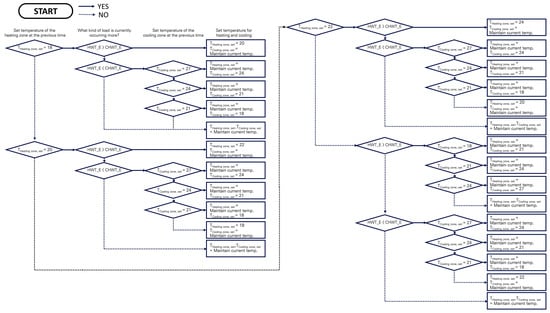
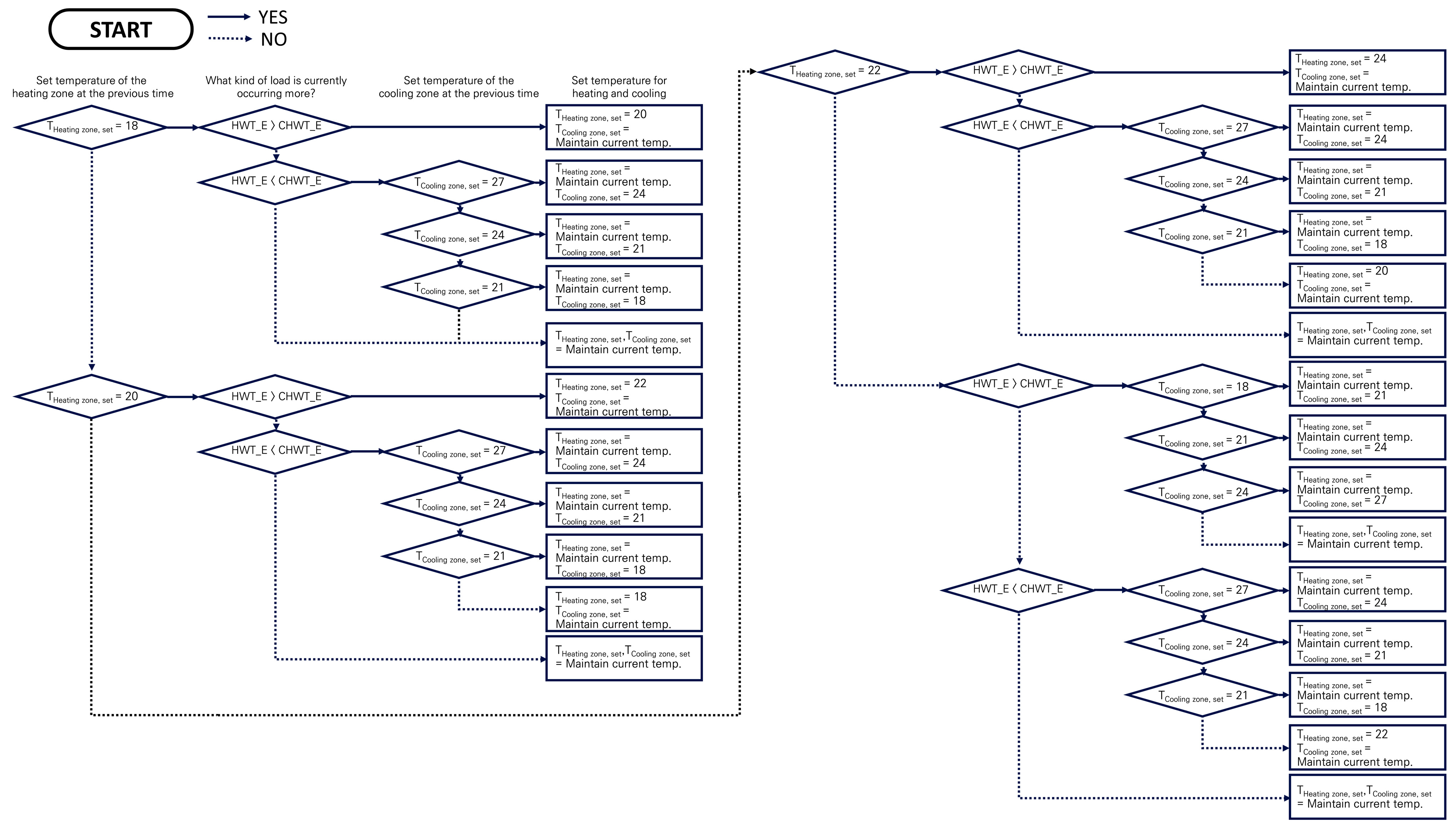
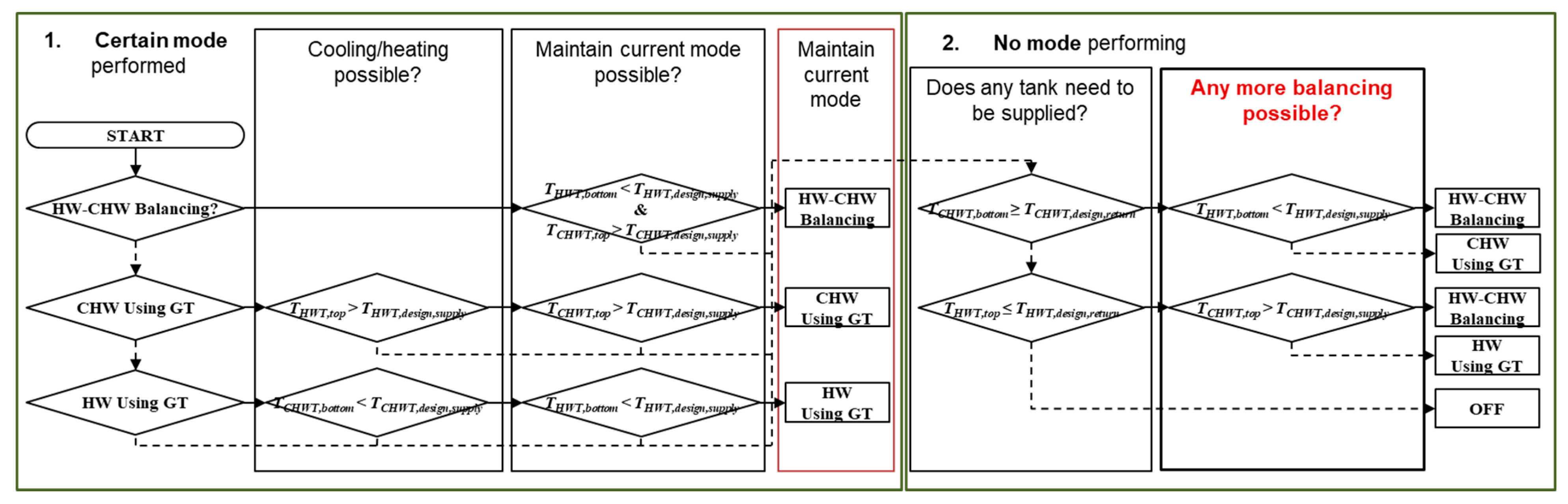
Load reset control (LRC) extends these concepts by dynamically modulating set temperatures to balance loads in real time, thereby maximizing SHC utilization and minimizing reliance on auxiliary heating or cooling. Shin et al. [24] introduced the foundational ‘load-balancing’ approach, and Lee et al. [25] and Lee and Shin [2] advanced this into a practical real-time LRC framework. In this study, the LRC mechanism follows the decision-making logic established in our previous work [2], where the algorithm assesses available thermal capacity by monitoring real-time energy levels in stratified thermal storage tanks. As illustrated in the control logic flowchart (Figure 1, adapted from [2]), the algorithm determines the optimal setpoint temperature based on these tank temperatures. This setpoint then serves as the operational input for the indoor temperature controllers (TRNSYS Type 2 differential controllers). to align with international control engineering nomenclature, ‘Reset’ specifically refers to ‘Setpoint Reset’—the dynamic adjustment of target temperatures based on demand—consistent with established HVAC standards, distinguishing it from the integral (reset) action in PID theory.
Figure 1.
Load reset control logic flowchart [2].
2.3. Application of Literature Review to This Study
The literature reviewed in Section 2.1 and Section 2.2 establishes a foundational framework for assessing the performance of LRC-applied SHC systems in relation to WELL Building Standard indicators in this study.
Section 2.1 highlights thermal comfort as a core health indicator within WELL, serving as the primary evaluation criterion for occupant well-being. WELL emphasizes maintaining the PMV between −0.5 and +0.5 for at least 90% of occupied hours in at least 90% of regularly occupied spaces (Feature T01: Thermal Performance). The promotion of radiant thermal control systems (Feature T05: Radiant Thermal Comfort) for at least 50% of regularly occupied areas further integrates radiant terminals into compliant designs. The comparison with LEED underscores WELL’s distinct human-centered priority over purely environmental metrics, justifying this study’s focus on health outcomes.
Section 2.2 provides the technical basis for balancing energy efficiency and comfort in SHC configurations. Studies by Byrne et al. [13,14,15,16], Joo et al. [17], Ghoubali et al. [18], Shin et al. [19], and Lee et al. [21] demonstrate substantial energy savings and improved COP through heat recovery, thermal storage integration, and optimized operation under simultaneous or partial loads. These findings inform this study’s system setup, particularly the use of water-source heat pumps, thermal storage tanks, and radiant terminals to enhance heat recovery efficiency while addressing load imbalances. The LRC methodologies outlined in the studies by Shin et al. [24], Lee et al. [25], and Lee and Shin [2] offer a practical mechanism for real-time setpoint modulation within the comfort range, directly aligning with WELL’s thermal comfort requirements by maximizing SHC utilization and minimizing auxiliary energy use.
By integrating these insights, this study quantitatively evaluates LRC-integrated SHC systems against WELL’s health-focused criteria. PMV compliance and radiant terminal utilization—both explicitly prioritized in WELL—serve as primary performance indicators. Comparative analyses examine energy consumption and thermal comfort across control strategies (fixed setpoint vs. PMV-based vs. LRC) and terminal types (convective vs. radiant), demonstrating the potential of LRC to achieve WELL-compliant comfort with superior energy efficiency. Therefore, rather than relying on complex direct PMV control or computationally heavy AI algorithms, this study aims to evaluate the extent to which the practical LRC strategy utilizing dynamic temperature setpoint adjustments within an SHC environment can realistically satisfy the stringent WELL PMV criteria while simultaneously optimizing energy performance.
3. Research Methods
3.1. Comparative Case Setup
This study configures the base plant system with water-source heat pumps and thermal storage tanks for both hot and chilled water. Two terminal types are compared: convection terminals (CONV), representing conventional all-air or fan–coil systems, and radiant terminals (RAD), which are promoted under WELL Feature T05 (Radiant Thermal Comfort). For control strategies, three approaches are evaluated:
- Fixed setpoint control (SP): Constant indoor air temperature setpoints of 26 °C for cooling and 20 °C for heating.
- Predicted mean vote control (PMV): Real-time adjustment to maintain the PMV between −0.5 and +0.5, aligning with WELL’s primary thermal comfort criterion (Feature T01: Thermal Performance).
- Load reset control (LRC): Dynamic modulation of setpoints within the comfort range—heating setpoints between 20 °C and 23 °C and cooling setpoints between 23 °C and 26 °C—to balance heating and cooling loads while preserving acceptable thermal conditions.
Although LRC adopts the WELL thermal comfort framework by referencing the PMV range of −0.5 to +0.5 as a guideline for acceptable conditions, its primary objective is to achieve energy savings through load balancing by dynamically adjusting dry-bulb temperature setpoints. Therefore, the control logic operates solely based on air temperature rather than direct PMV calculation or feedback. In practical commercial building operations, deploying a comprehensive sensor network to continuously measure all six PMV variables is often constrained by high economic costs and technical complexity. Consequently, LRC may not precisely achieve or maintain the target PMV values under varying conditions, potentially leading to deviations from the exact PMV compliance required by WELL Feature T01. However, the evaluation framework in this study is explicitly designed to assess the extent to which this practically viable, temperature-based LRC can satisfy the stringent WELL PMV criteria despite these inherent operational deviations. These terminal types and control strategies are combined into six simulation cases, as summarized in Table 1.
Table 1.
Cases combining systems and control methods.
3.2. Quantitative Evaluation Indicators
For fully mechanically conditioned indoor environments, such as those equipped with SHC systems, the most methodologically appropriate thermal comfort indicators are the predicted mean vote (PMV) and predicted percentage of dissatisfied (PPD) [26,27], alongside operative temperature [4,27] and Standard Effective Temperature (SET) [28]. Among these, the PMV—developed based on Fanger’s heat balance model—quantitatively assesses human heat loss through mechanisms such as convection, radiation, and evaporation. It predicts the average thermal sensation of a large group of people by integrating six key variables: air temperature, relative humidity, air velocity, mean radiant temperature, clothing insulation, and metabolic rate. This comprehensive approach makes the PMV highly accurate and directly applicable to controlled indoor spaces. The PMV is formalized in international standards, including ASHRAE Standard 55 and ISO 7730, and serves as a core thermal comfort metric in the WELL Building Standard (Feature T01: Thermal Performance) and LEED certification programs. Therefore, this study adopts the PMV as the primary quantitative indicator for evaluating thermal comfort, with compliance defined as maintaining the PMV between −0.5 and +0.5 in accordance with WELL requirements.
For energy performance, common metrics include Energy Use Intensity (EUI) [29], which normalizes energy consumption per unit floor area. However, since all simulation cases in this study involve the same building geometry and floor area, normalization by area provides no additional differentiation. Accordingly, total annual energy consumption is used as the quantitative energy evaluation indicator.
3.3. Simulation Setup
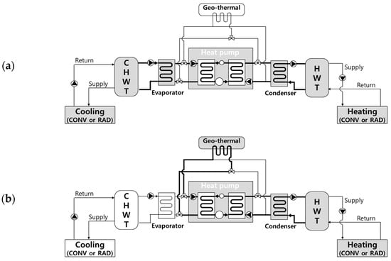
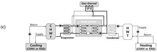
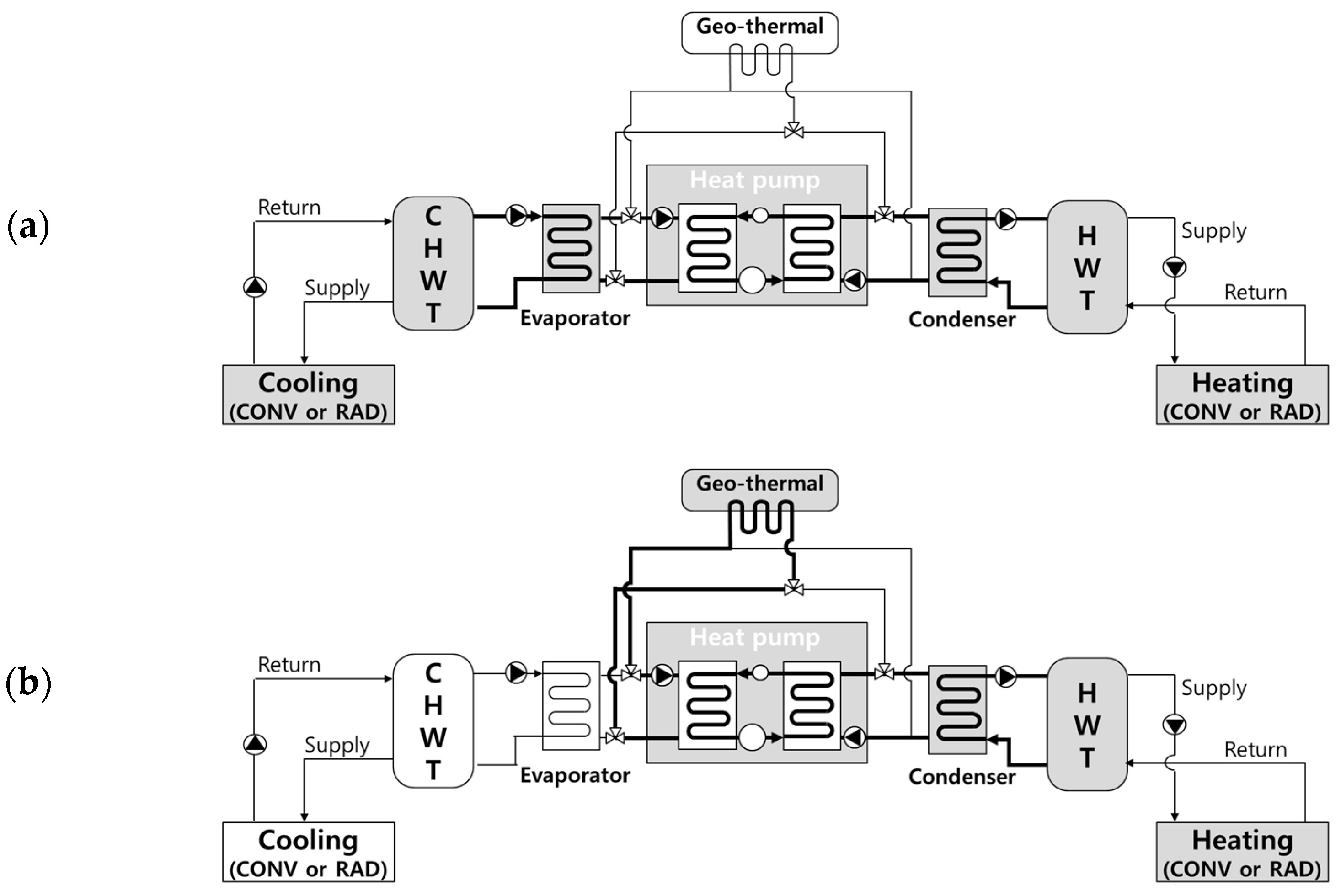
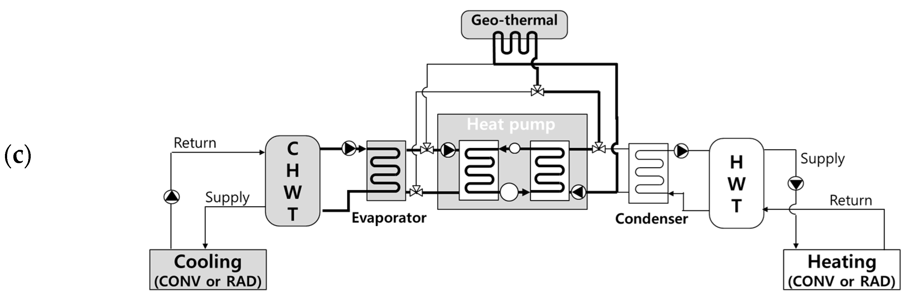
This study compares energy flows and consumption across key processes for configurations equipped with convective terminals (CONV) and radiant terminals (RAD) to evaluate the energy performance of Simultaneous Heating and Cooling systems with Thermal storage tanks (SHCwT). The system configuration and heat pump (or chiller) ON–OFF control logic are partially adapted from prior research [19], as illustrated in Figure 2 (system schematic) and Figure 3 (operation strategy diagram). In the modeled setup, geothermal heat (GT) serves as an additional heat source for a single water-cooled chiller. The chiller and circulation pumps operate or stop based on monitored temperatures at critical nodes in the hot water (HW) and chilled water (CHW) storage tanks.
Figure 2.
SHCwT system diagram: (a) HW-CHW Balancing; (b) HW using GT; and (c) CHW using GT.
Figure 3.
Operation strategy for proposed SHCwT system (Mode selection).
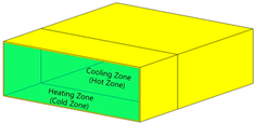
The SHCwT system is specifically designed for buildings experiencing concurrent heating and cooling demands. Accordingly, simulations target winter conditions in Seoul, Korea, where low outdoor air temperatures combined with internal heat gains in certain zones can lead to simultaneous heating and cooling requirements. The target building comprises two distinct thermal zones: a heating zone and a cooling zone. Simulations focus on representative winter scenarios with internal heat generation in the cooling zone under cold outdoor conditions.
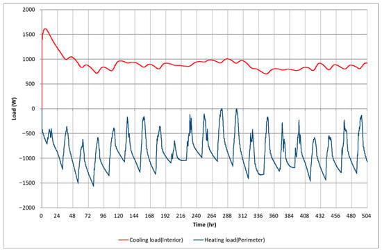
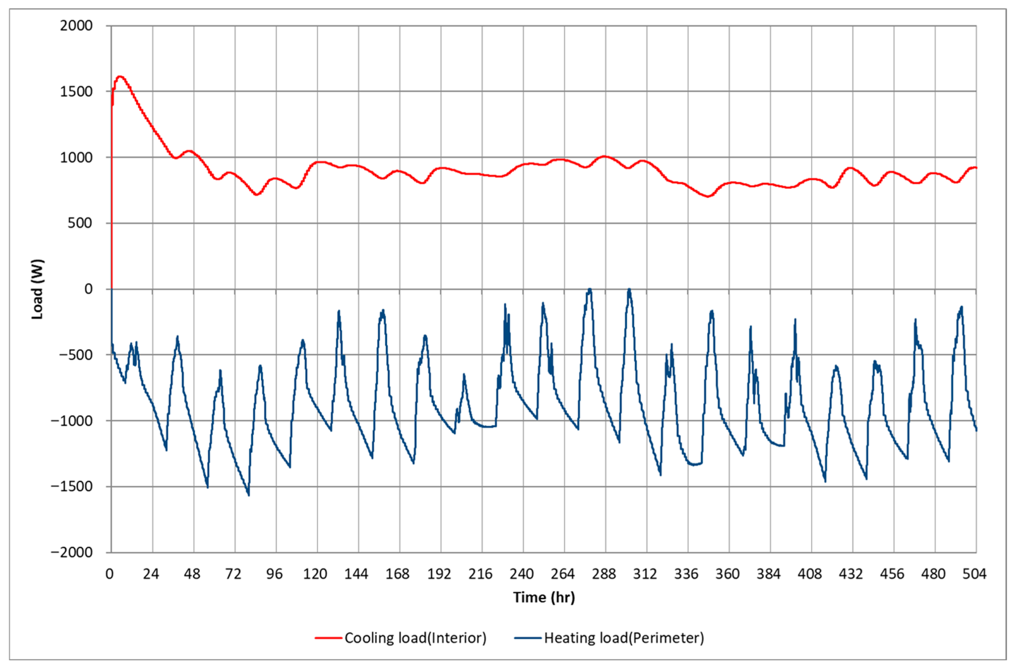
The primary building characteristics, including geometry, envelope properties, and internal loads, are detailed in Table 2. A 3D isometric view illustrating the thermal zoning layout is included within Table 2 to provide a clear visual representation of the simulation environment. As depicted, the space is divided into a heating zone (North, 28.5 m2) and a cooling zone (South, 28.5 m2). In this simulation model, an extreme boundary condition was intentionally established to rigorously stress-test the simultaneous load-balancing performance of the system. Specifically, the heating zone was assumed to have zero internal heat gains (no occupants, lighting, or equipment), with only external solar gains through windows considered. Conversely, the cooling zone was assumed to house a constant 1840 W sensible heat load (e.g., servers) without latent loads. While this assumption in the heating zone represents a theoretical extreme, it was deliberately chosen to guarantee a distinct and continuous simultaneous heating and cooling demand, thereby isolating the performance evaluation of the LRC logic without the interference of fluctuating internal schedules. Heating and cooling load profiles were generated using TRNSYS 18 [30] based on Seoul’s Typical Meteorological Year 2 (TMY2) weather data. The resulting hourly load profiles and aggregated thermal loads are presented in Table 3 and Figure 4, respectively.
Table 2.
Condition of target building.
Table 3.
Actual load amount.
Figure 4.
Load profile.
Component capacities for the SHCwT system were determined by applying a 10% safety factor to the maximum cooling load of 1616 W, consistent with standard HVAC design practices to account for uncertainties, such as load variations, equipment degradation, and operational margins. The chiller capacity was sized accordingly to provide sufficient cooling output with this margin during peak conditions. The thermal storage tank capacities (for both hot and chilled water) were determined to enable storage of the full daily recovered heating and cooling energy through heat recovery in the SHC process. This approach ensures the system can decouple non-simultaneous loads while allowing direct comparison of performance differences attributable solely to the terminal type.
For both convective (CONV) and radiant (RAD) terminal configurations, primary-side circulation pumps are required to manage flow between the chiller and the chilled water tank (CHWT), as well as between the chiller and the hot water tank (HWT). On the secondary side, each configuration also requires one additional pump per tank: for CONV, secondary pumps circulate water between the CHWT/HWT and the air-handling units (AHUs); for RAD, secondary pumps circulate water between the CHWT/HWT and the radiant zone panels. Thus, the total number of circulation pumps is the same in both configurations. In contrast, fan operation is required only in the CONV configuration to distribute conditioned air from the AHUs or fan–coil units to the zones. The RAD configuration relies solely on hydronic circulation through the building’s panel systems, eliminating the need for fans and associated fan energy consumption. This setup ensures that differences in energy performance between CONV and RAD arise primarily from terminal-specific heat transfer characteristics, airflow requirements, and auxiliary energy use, while maintaining comparable pumping demands.
Component input data, including equipment specifications, are summarized in Table 4. Previous studies on SHC systems typically implemented their own custom-developed control algorithms, which are often difficult to reproduce or modify in standard simulation environments. For this reason, TRNSYS was selected as the simulation platform. TRNSYS supports flexible implementation of a custom control logic through its equation blocks and logical components, without requiring specialized controller types. This capability enabled the development of the SHC system control strategies (illustrated in Figure 3), as well as the dynamic setpoint determination in LRC (illustrated in Figure 1).
Table 4.
Components’ input data for each case.
As detailed in Table 4, the chiller operates with a set temperature of 10 °C to efficiently charge the Chilled Water Tank (CHWT). However, the actual design supply temperature from the CHWT to the radiant terminals is maintained at 15 °C. This specific supply temperature was strategically selected to ensure that the radiant surface temperature remains above the typical indoor dew point, thereby structurally minimizing the risk of surface condensation during cooling operations.
To prevent control loop hunting and equipment short-cycling, this study replaces continuous PID control with a TRNSYS Type 2 Differential Controller featuring a predefined hysteresis deadband. Furthermore, the LRC algorithm structurally ensures dynamic stability by adjusting setpoints based on the usable thermal capacity thresholds of the stratified tanks, rather than reacting to instantaneous room load fluctuations. Because the proposed SHC system inherently leverages this substantial thermal inertia of both the stratified tanks and the building mass, this study focuses on evaluating the macroscopic, long-term balance between energy efficiency and PMV compliance. Consequently, detailed micro-level transient response analyses during sudden load surges fall outside its intended scope.
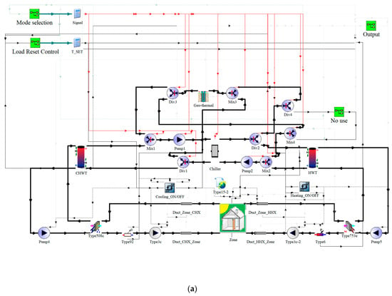
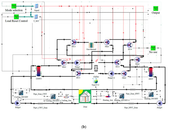
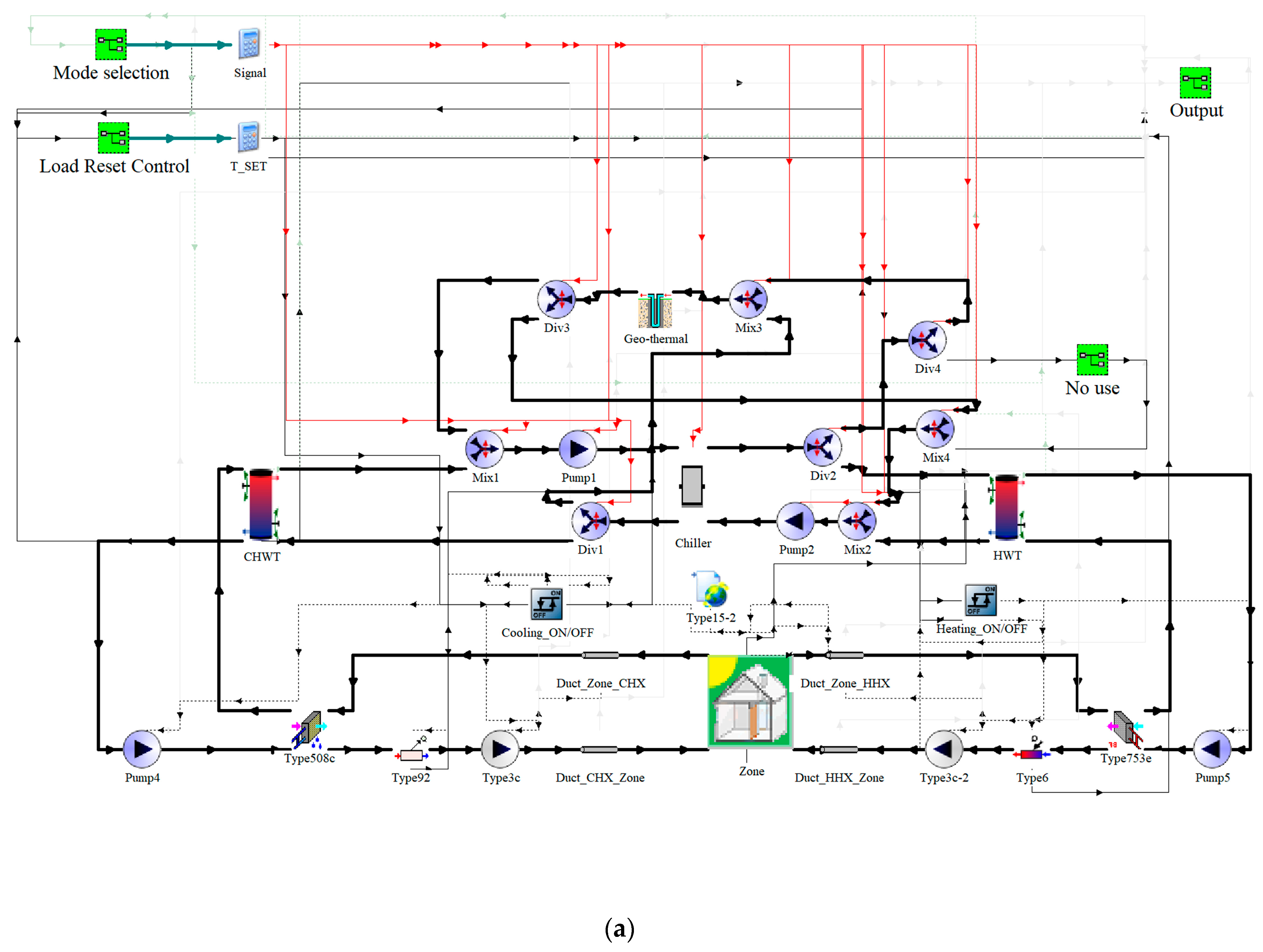
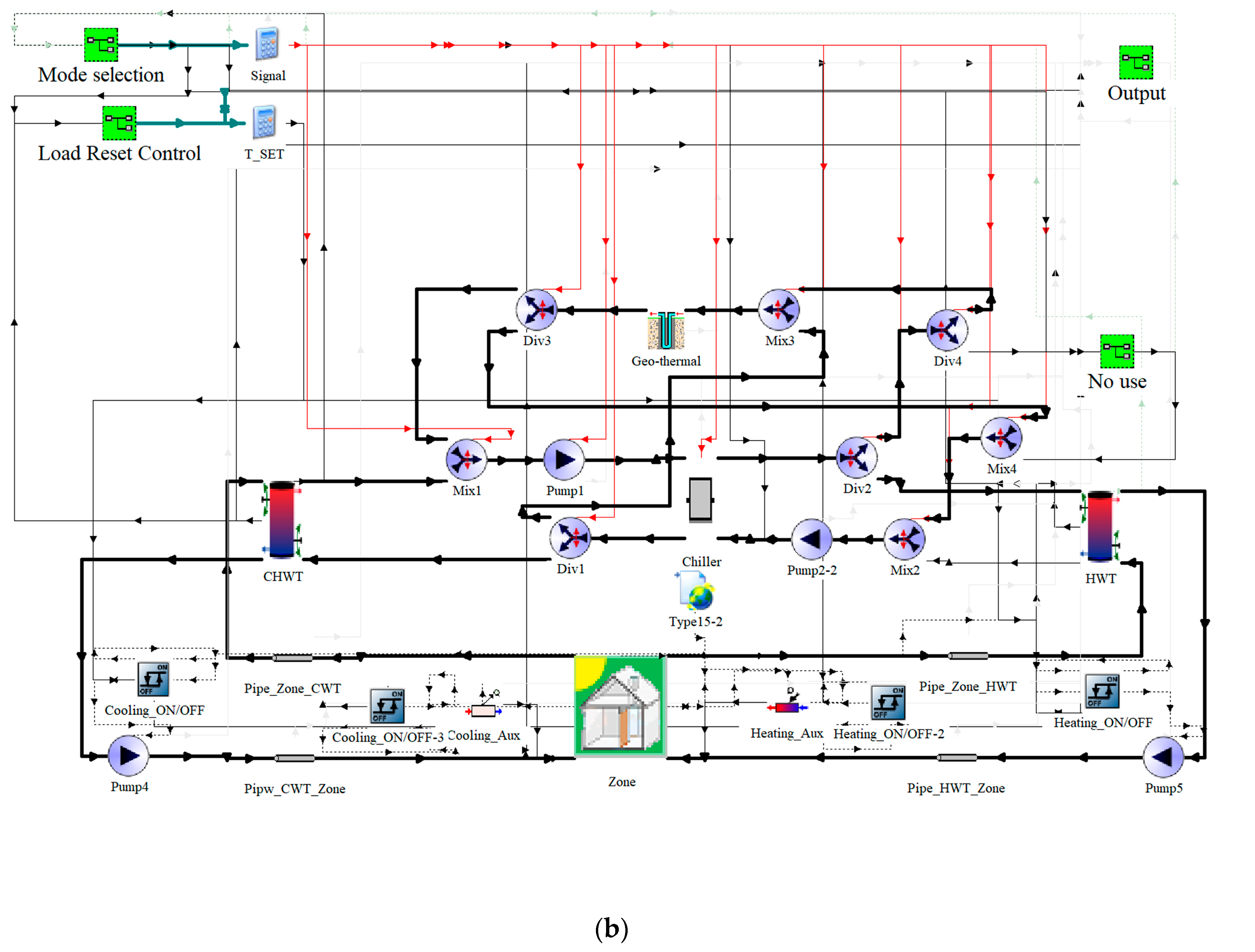
The detailed simulation schematics are presented in Figure 5. Representative diagrams are shown for the two cases that incorporate LRC: the CONV-LRC configuration and the RAD-LRC configuration. These diagrams illustrate the custom control logic implemented through combinations of TRNSYS equation blocks for dynamic setpoint determination. The remaining four cases (CONV-SP, CONV-PMV, RAD-SP, and RAD-PMV) follow analogous structures, differing only in the terminal type and control strategy module.
Figure 5.
System model (TRNSYS): (a) CONV cases; (b) RAD cases.
4. Results and Discussion
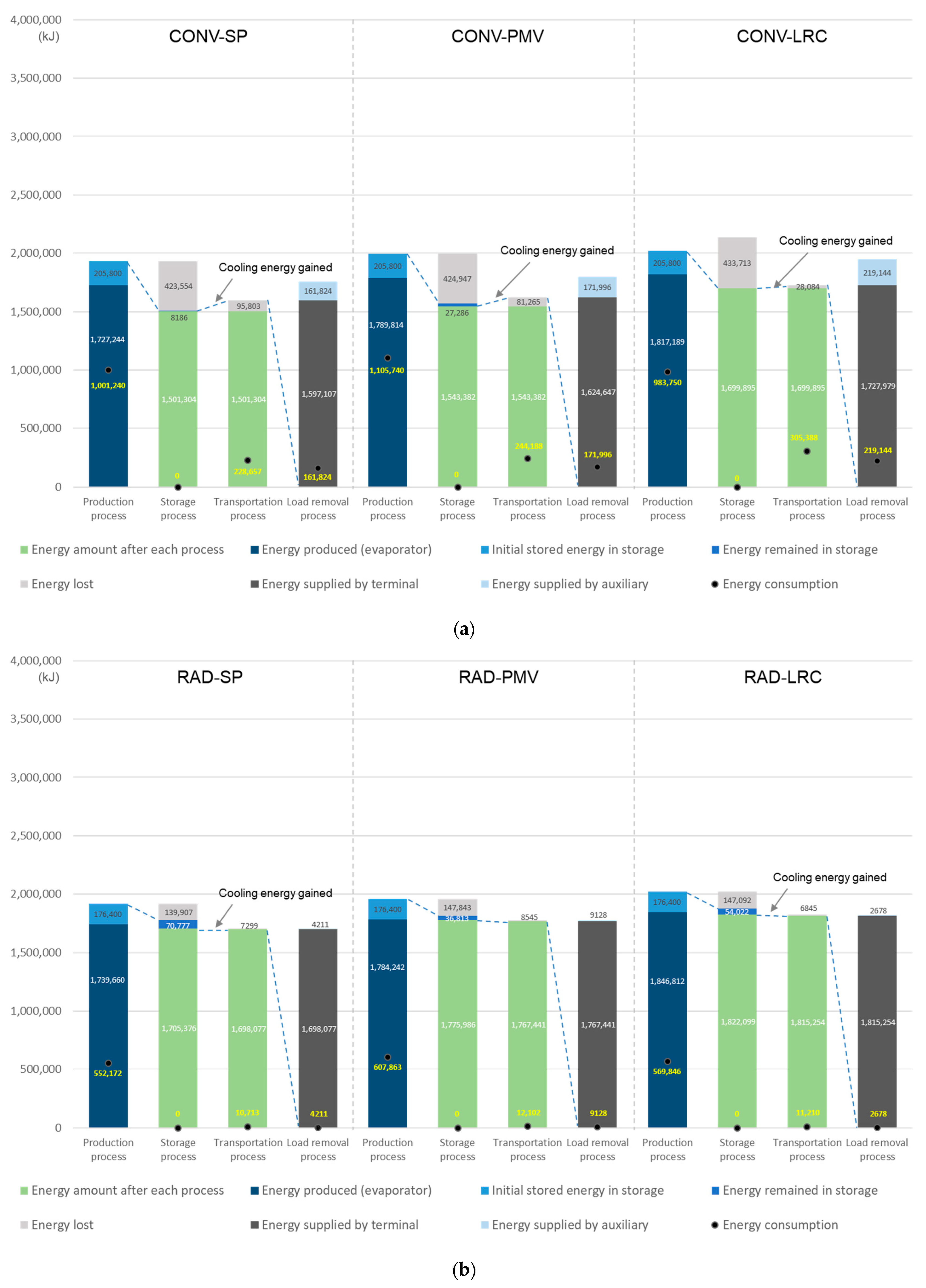
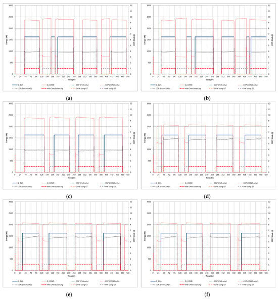
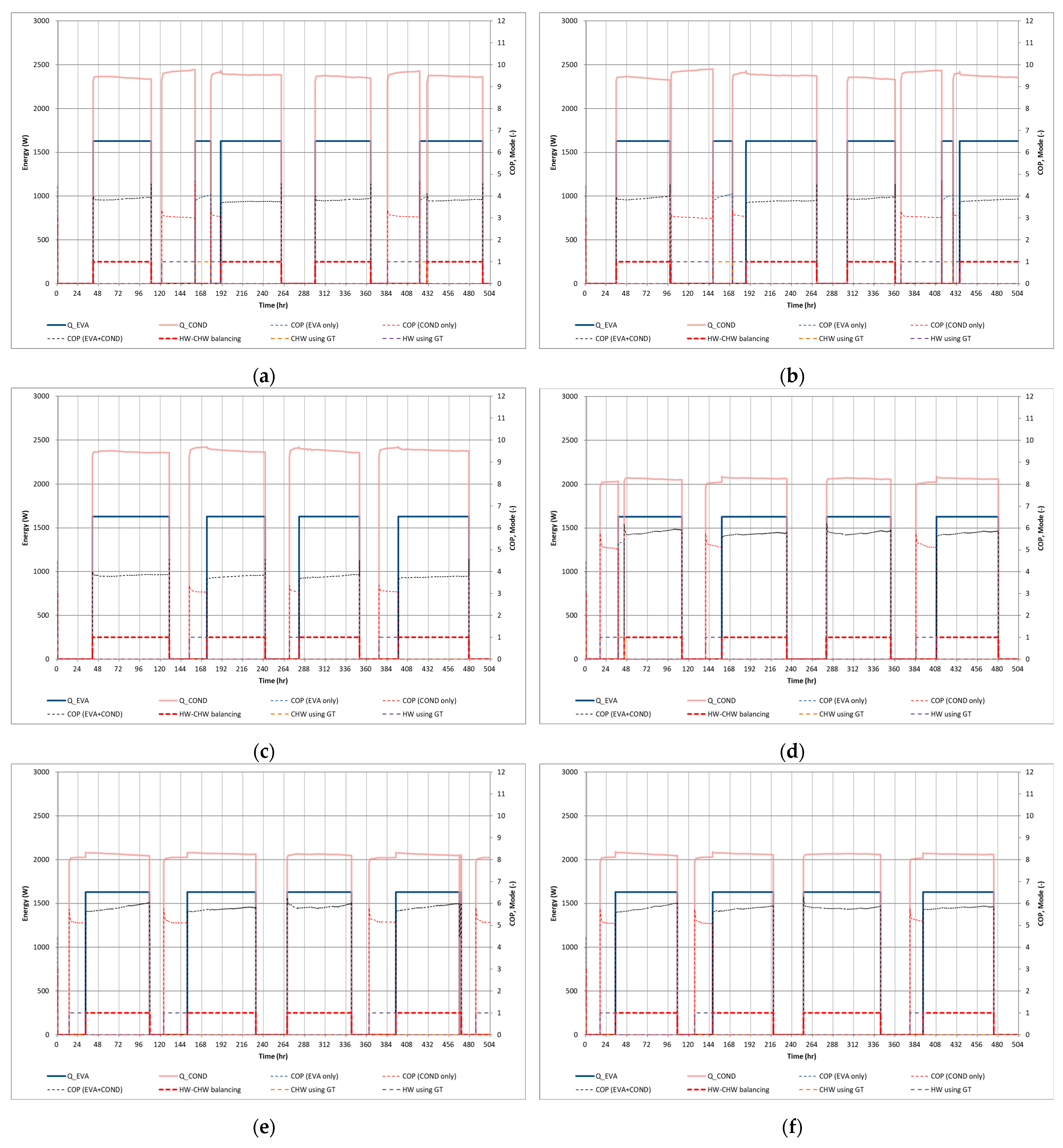
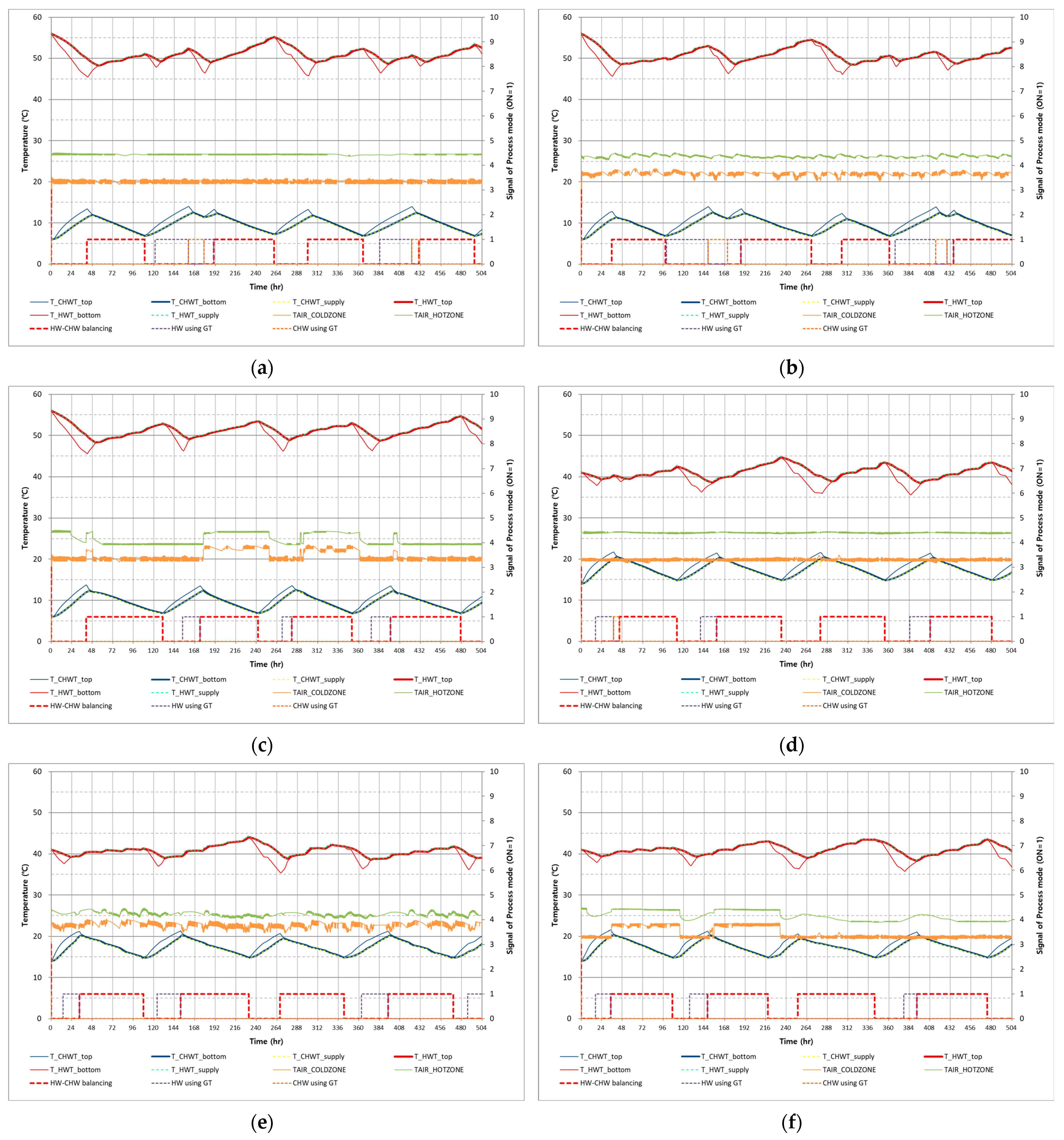
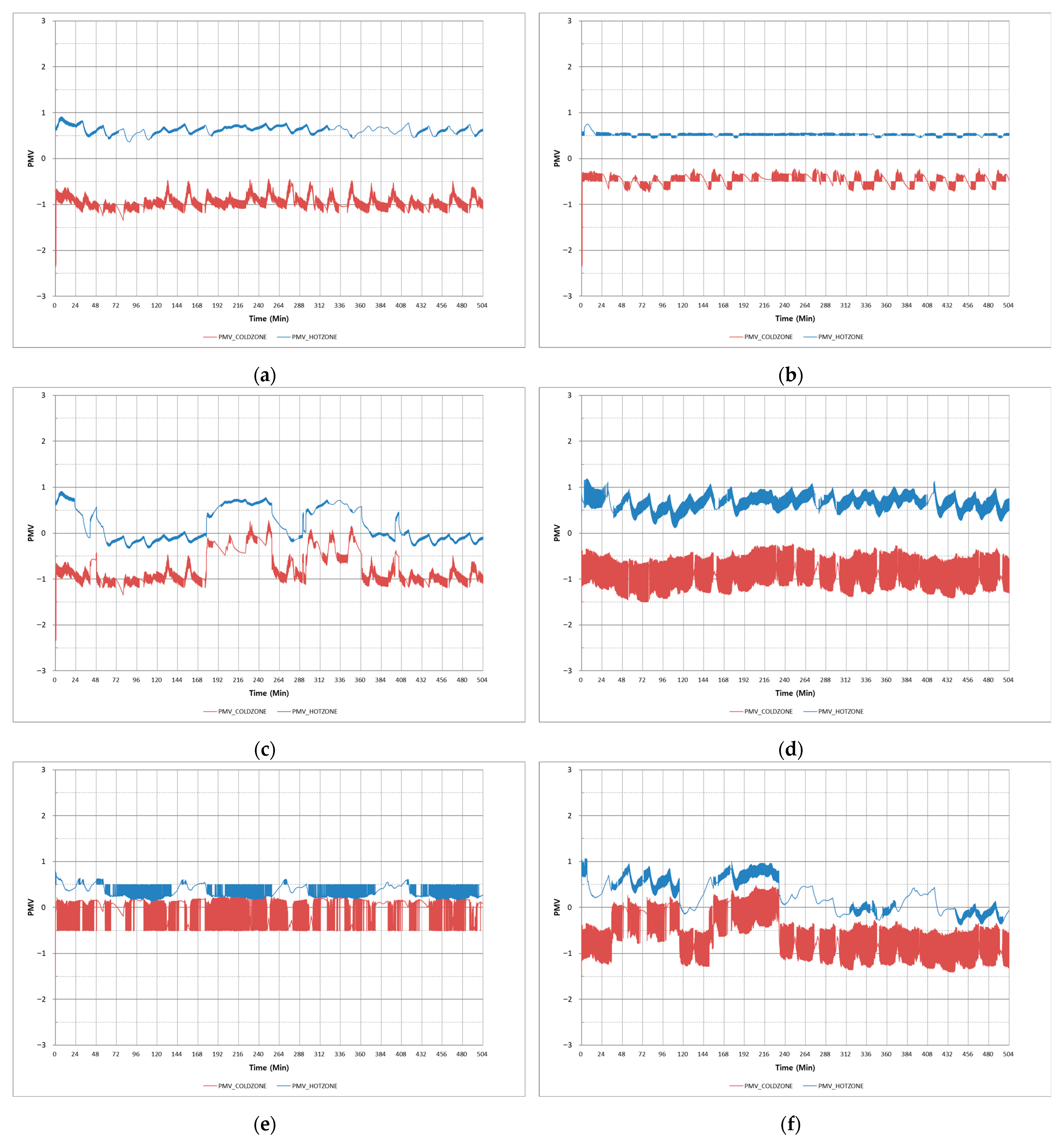
The detailed energy outputs from the chiller and auxiliary systems are summarized in Table 5. The energy flows and consumption for each simulation case are presented in Figure 6 and Figure 7. The chiller energy consumption and Coefficient of Performance (COP) are shown in Figure 8. The key temperatures and mode signals are illustrated in Figure 9. The PMV values in the heating and cooling zones are depicted in Figure 10. Additionally, the PMV compliance rates, representing the percentage of time the zones meet the WELL criteria are summarized in Table 6. In this chapter, the simulation results are analyzed separately for heating and cooling performance. The analysis focuses on comparing energy consumption, chiller efficiency, thermal comfort (PMV compliance), and system operation characteristics across the six cases.
Table 5.
Energy output of chiller and auxiliary system.
Figure 6.
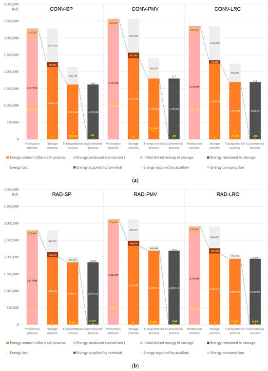
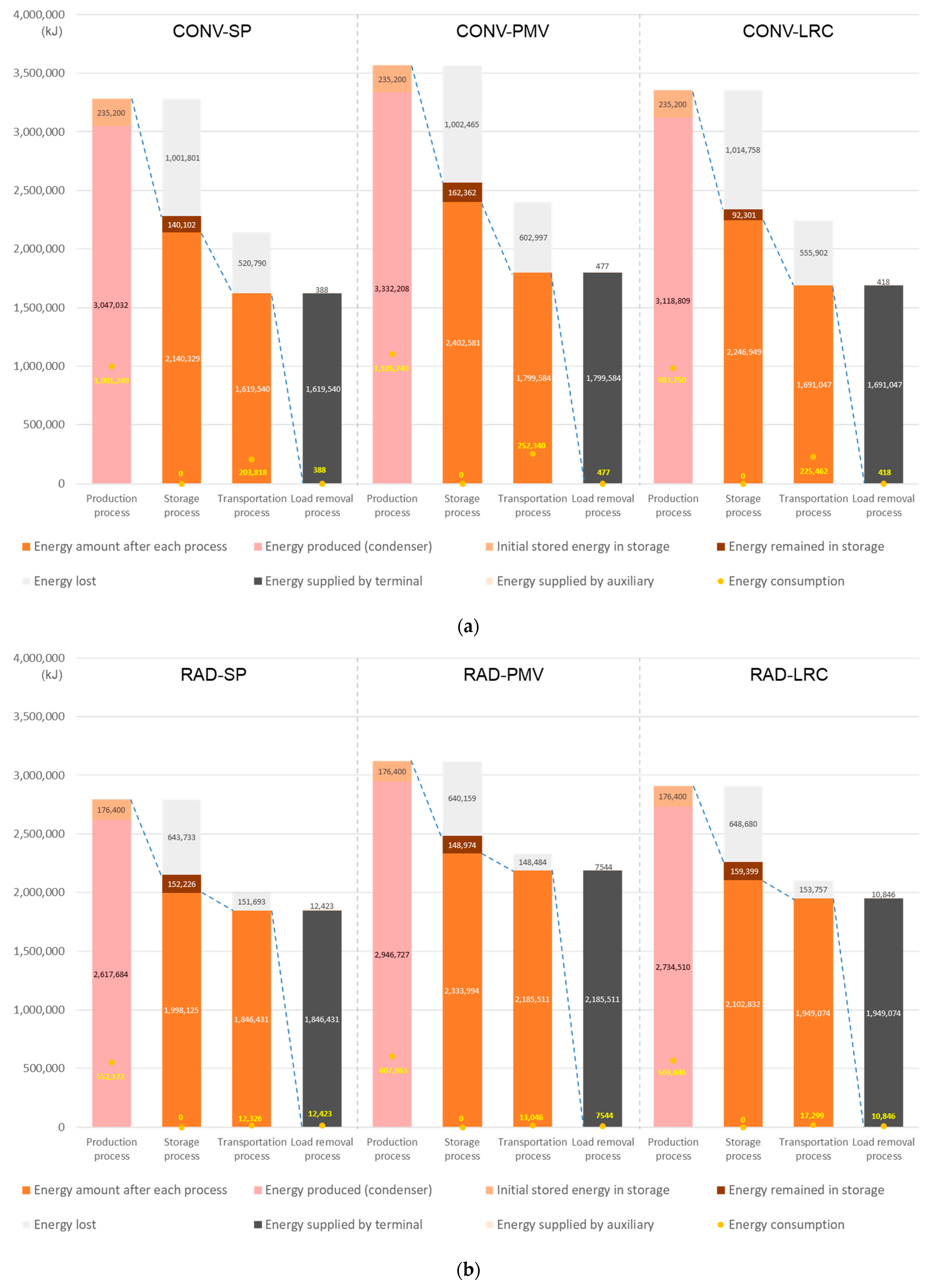
Energy flow and consumption for heating: (a) CONV cases; (b) RAD cases.
Figure 7.
Energy flow and consumption for cooling: (a) CONV cases; (b) RAD cases.
Figure 8.
Chiller energy and COP: (a) CONV-SP; (b) CONV-PMV; (c) CONV-LRC; (d) RAD-SP; (e) RAD-PMV; and (f) RAD-LRC.
Figure 9.
Temperatures and mode signal graph: (a) CONV-SP; (b) CONV-PMV; (c) CONV-LRC; (d) RAD-SP; (e) RAD-PMV; and (f) RAD-LRC.
Figure 10.
PMV graph: (a) CONV-SP; (b) CONV-PMV; (c) CONV-LRC; (d) RAD-SP; (e) RAD-PMV; and (f) RAD-LRC.
Table 6.
PMV compliance rates (%) according to WELL criteria across simulation cases.
4.1. Heating
Table 5 provides a detailed breakdown of the energy output from the chiller and auxiliary systems across all simulated cases, categorized by operation. As summarized in the table, the chiller’s energy production varies significantly depending on the control strategy and terminal type, with auxiliary contributions filling gaps where heat pump output alone is insufficient. For instance, the balancing mode dominates the chiller output in most cases, contributing 74.9% to heating in CONV-SP, rising to 85.0% heating in CONV-LRC. This indicates that LRC enhances the utilization of the simultaneous heating–cooling mode, reducing reliance on geothermal tank (GT) modes. Similarly, in RAD configurations, balancing mode accounts for over 82% of the heating output in SP and LRC, highlighting LRC’s effectiveness in optimizing heat recovery and minimizing supplemental GT operations
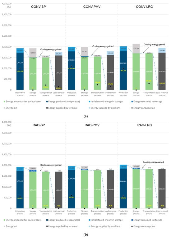
Figure 6 illustrates the energy flows and consumption for the fixed setpoint (SP), predicted mean vote (PMV), and load reset control (LRC) strategies, separated into convective terminal cases (CONV; Figure 6a) and radiant terminal cases (RAD; Figure 6b). Overall, the CONV cases exhibit higher total energy production compared with the RAD cases, as evidenced by the higher chiller totals in Table 5 (e.g., 4,774,276 kJ for CONV-SP vs. 4,357,344 kJ for RAD-SP). This difference arises primarily because convective terminals require higher heating supply water temperatures than radiant terminals, leading to greater heat losses to the surrounding environment during distribution and, thus, higher “energy lost” in the CONV configuration.
In the production process, CONV cases also show higher energy consumption, although the chiller COP is generally higher in RAD cases (as depicted in Figure 8). The improved COP in RAD configurations stems from the smaller temperature lift required between the source and the supply water. Transportation energy consumption is notably higher in CONV due to the substantial fan power required for air circulation in air-handling units or fan–coil systems, which is absent in RAD.
Despite higher energy production in CONV, the effective energy supplied to the zones during load removal is greater in RAD cases. This outcome is attributed to the indirect heat transfer mechanism in radiant systems: heat is first stored in the thermal mass of the floor/ceiling/wall, which then gradually influences air temperature, resulting in more efficient delivery to the space load.
Across both terminal types, PMV control incurs the highest energy consumption, reflecting the additional energy required to strictly satisfy the PMV range of −0.5 to +0.5. As shown in Figure 9, PMV control maintains room air temperatures consistently above 20 °C, exceeding the SP threshold and, thus, consuming more energy than SP or LRC to achieve tighter comfort compliance. This pursuit of absolute comfort is quantitatively validated in Table 6, where PMV control strategies demonstrate the highest PMV compliance rates, ensuring the occupied spaces meet the WELL criteria for the maximum possible duration. Consequently, PMV cases exhibit more stable PMV values overall (Figure 10). RAD-PMV displays larger PMV variations than CONV-PMV but remains more stably within the −0.5 to +0.5 band, likely due to the thermal inertia of the radiant surfaces, which dampens rapid temperature fluctuations compared with the faster-responding convective air systems.
The load removal is approximately 4.2% higher for CONV-LRC than for CONV-SP and 6.4% lower than for CONV-PMV, while the energy consumption is 7.7% higher than for CONV-SP and 12.3% lower than for CONV-PMV. This balance effectively demonstrates LRC’s objective: maximizing thermal comfort—reflected by the higher PMV compliance rate in Table 6 compared with the baseline SP—while prioritizing energy savings.
The load removal is 5.3% higher for RAD-LRC than for RAD-SP and 12.1% lower than for RAD-PMV, with 3.5% higher energy consumption than for RAD-SP and 5.1% lower than for RAD-PMV. These results indicate that LRC does not always minimize energy consumption below the SP baseline. However, this slight increase in energy use is offset by a measurable improvement in the PMV compliance rate in Table 6, highlighting a strategic trade-off.
Nevertheless, LRC dynamically adjusts setpoints within the comfort range to balance heating and cooling loads in SHC systems. This approach achieves the intended purpose of LRC: providing thermal comfort with competitive energy efficiency, rather than pursuing the absolute minimum energy use at the expense of comfort. In contrast, achieving near-perfect compliance with the WELL PMV range of −0.5 to +0.5 requires the significantly more energy-intensive PMV control strategy.
A potential future enhancement could involve developing an advanced LRC variant that resets setpoints based on real-time PMV calculations instead of fixed air temperature bands. Such a modification might combine the load-balancing energy advantages of the current LRC with stricter adherence to WELL’s thermal comfort criteria.
4.2. Cooling
Table 5 summarizes the chiller and auxiliary energy output for cooling across all cases, broken down by operation mode. Balancing mode (HW-CHW balancing) consistently dominates chiller cooling production, accounting for 90.9% in CONV-SP, 100% in CONV-LRC, 97.7% in RAD-SP, and 100% in both RAD-PMV and RAD-LRC. This demonstrates that LRC strongly favors simultaneous heating–cooling operation (Figure 2a), virtually eliminating the need for CHW using the GT mode. These trends align with the operation logic in Figure 3.
Figure 7 illustrates the energy flows and consumption for SP, PMV, and LRC strategies in convective (CONV, Figure 7a) and radiant (RAD, Figure 7b) terminal configurations. Unlike the heating case, total energy production is nearly identical between CONV and RAD configurations. Although convective terminals typically operate with lower cooling supply water temperatures than radiant terminals, the temperature differential with the ambient environment is relatively small during the cooling season, resulting in lower overall heat losses compared with the heating mode. Nonetheless, energy lost remains slightly higher in CONV than in RAD, and the effective energy supplied to the zones during load removal is marginally greater in RAD—as observed in heating—likely offsetting the difference through more efficient terminal heat transfer.
In the production process, CONV cases exhibit higher energy consumption, consistent with the heating results. This is primarily attributed to the chiller’s higher COP in RAD configurations, which benefits from the smaller temperature lift required across the cooling cycle in radiant systems.
In certain cases, energy lost during transportation becomes negative, meaning more energy is delivered to the load removal process than was present in the storage process. This phenomenon occurs when return water from the cooling zone—warmed by the load—loses heat to the cooler ambient environment, effectively providing additional free cooling capacity. Although the design return temperature for chilled water is below ambient temperature, the actual return temperatures under dynamic load control often exceed ambient temperature, leading to this beneficial heat rejection effect.
In the CONV configuration, this negative energy loss effect is more pronounced because the system relies on air ducts to transport conditioned air to the zones. Ducts typically have a much larger surface area exposed to the ambient environment compared with the hydronic pipes used in the RAD configuration. As a result, CONV experiences greater heat transfer (heat rejection) from the warmer return air or water-carrying ducts to the surroundings, leading to relatively more free cooling energy gain during transportation. In contrast, the RAD system uses only compact hydronic piping with a significantly smaller exposed surface area, resulting in limited external heat exchange and, thus, a less pronounced negative energy loss during the transportation process.
This difference in surface area and heat transfer characteristics contributes to the observed variations in effective energy delivery to the load removal process between CONV and RAD, even when the initial stored energy is comparable.
Energy consumption in the transportation process is significantly higher in the CONV configuration compared with RAD, primarily because CONV relies on fans within AHUs to circulate and distribute conditioned air through ducts to the zones. This fan operation incurs substantial power throughout the operating hours, whereas the RAD configuration uses only hydronic piping for water circulation to radiant panels, eliminating the need for fans and thereby removing fan-related energy use from the transportation process.
Across both terminal types, PMV control results in the highest energy consumption, as it prioritizes strict adherence to the PMV range of −0.5 to +0.5. As evident in Figure 9, PMV control maintains room air temperatures consistently below 26 °C, exceeding the SP threshold and, thus, requiring more energy than SP or LRC to achieve precise comfort compliance. This pursuit of strict comfort is quantitatively validated in Table 6, where the PMV control strategies demonstrate the highest PMV compliance rates, ensuring that the spaces meet the WELL criteria for the maximum possible duration. Consequently, PMV cases display the most stable PMV profiles overall (Figure 10). RAD-PMV exhibits larger PMV variations than CONV-PMV but maintains values more consistently within the acceptable range, likely due to the thermal inertia of the radiant surfaces that buffer rapid changes in operative temperature.
The load removal is approximately 7.6% higher for CONV-LRC than for CONV-SP and 6.0% higher than for CONV-PMV, while the energy consumption is 7.7% higher than for CONV-SP but only 0.9% lower than for CONV-PMV. The load removal is about 6.5% higher for RAD-LRC than for RAD-SP and 2.6% higher than for RAD-PMV, with 2.9% higher energy consumption than for RAD-SP but 7.9% lower than for RAD-PMV. These outcomes demonstrate that LRC effectively balances the energy-saving characteristics of SP control with the superior comfort performance of PMV control. By sacrificing a marginal amount of energy compared to the SP baseline, LRC secures a meaningful improvement in the PMV compliance rate (Table 6), delivering enhanced thermal conditions with highly competitive energy use in SHC systems.
However, as analyzed in Section 4.1 for heating, since the current LRC relies solely on air temperature setpoints rather than direct PMV feedback, it cannot precisely maintain PMV at the exact target value under varying conditions. Nevertheless, as clearly evidenced by the compliance rates in Table 6, LRC still achieves higher overall thermal comfort than the SP baseline while consuming comparable or only modestly higher energy.
4.3. Trade-Off Analysis Among Control Strategies
As demonstrated in the preceding heating and cooling performance evaluations, pure PMV control consumed the most energy to tightly maintain the PMV target at zero, whereas the SP exhibited the most significant deviations from the acceptable comfort criteria. When comparing these control strategies for real-world application, a critical trade-off emerges between implementation complexity, energy savings, and thermal comfort.
While pure PMV control theoretically provides the highest level of comfort, it is inherently complex and cost-intensive to implement in practical building operations. It requires a sophisticated sensor network to continuously monitor six dynamic variables (e.g., mean radiant temperature, air velocity, and metabolic rate) in real-time. Furthermore, pure PMV control often consumes significant energy by continuously reacting to minor fluctuations to strictly maintain a PMV of zero.
In contrast, the proposed LRC strategy relies on standard dry-bulb temperature sensors and macroscopic system data (e.g., thermal storage tank capacities), significantly reducing implementation complexity. Although LRC may exhibit slight deviations from exact PMV = 0 targets compared with pure PMV control, it successfully maintains the indoor environment within the WELL comfort criteria (−0.5 to +0.5) while yielding substantial energy savings through systemic load balancing. Therefore, LRC is highly preferred in practical applications as an effective, low-complexity compromise that secures premium thermal comfort while prioritizing energy efficiency. While advanced strategies Model Predictive Control (MPC) could theoretically yield higher energy savings through future load predictions, they require bespoke physics models and intensive computational resources, limiting their widespread field application. Therefore, LRC stands out as the optimal practical choice for sustainable buildings. Furthermore, the superior stability of the RAD configuration in this context is closely related to the inherent thermal lag of the radiant panels. When integrated with the LRC strategy, this thermal lag acts as a stabilizing buffer that naturally absorbs minor environmental fluctuations, preventing rapid oscillations in the Mean Radiant Temperature (MRT) and ensuring consistent PMV stability. However, since this study used a constant internal load to isolate the LRC’s balancing logic, the results may vary under dynamic real-world schedules. While the high thermal inertia of RAD systems provides stability, it may also lead to delayed responses during sudden load fluctuations, causing temporary PMV deviations. In contrast, convective systems might respond more adaptively to variable loads. Further research is required to evaluate these transient behaviors under fluctuating occupancy profiles.
5. Conclusions
This study quantitatively evaluated the effectiveness of integrating load reset control (LRC) into simultaneous heating and cooling (SHC) systems with respect to the thermal comfort criteria of the WELL Building Standard, using detailed TRNSYSs. The analysis focused on whether SHC systems can simultaneously achieve substantial energy savings and WELL-compliant occupant thermal comfort, while examining the influence of terminal type and control strategy on overall performance. The main conclusions are as follows:
- Radiant terminals generally exhibited lower total energy consumption than convective terminals in both heating and cooling modes. This advantage stems primarily from the higher chiller COP due to smaller temperature lift requirements and the complete elimination of fan energy in RAD configurations. While radiant systems provide indirect heat transfer through thermal mass, leading to certain differences in energy delivery efficiency during load removal, the overall energy performance favors RAD.
- PMV control achieved the highest thermal comfort compliance by maintaining the most stable PMV values within the WELL range of −0.5 to +0.5, but it resulted in substantially higher energy consumption (typically 5–12% or more above SP or LRC) due to the need for aggressive adjustments to meet strict WELL criteria. In contrast, fixed setpoint control (SP) offered the lowest energy use but lower comfort performance, while LRC provided a balance: higher thermal comfort than SP with energy consumption comparable to or only modestly higher than SP, and much lower than PMV. Although PMV excels in precise comfort delivery, its large energy penalty limits practicality for balancing WELL certification and energy efficiency.
- The current load reset control (LRC), which dynamically resets air temperature setpoints within the comfort range (cooling: 20–23 °C; heating: 23–26 °C) without direct PMV feedback, cannot precisely maintain the exact target PMV value. Nevertheless, as consistently observed in both heating and cooling analyses, LRC still achieves slightly higher overall thermal comfort than SP while maintaining competitive energy performance—typically with 4–8% higher load removal than SP and 1–8% lower energy consumption than PMV control. This demonstrates that LRC effectively fulfills its intended purpose in SHC systems: optimizing thermal comfort through dynamic load balancing, without strictly minimizing energy below the SP baseline.
In conclusion, LRC applied to SHC systems represents a practical and effective strategy for balancing energy efficiency and occupant thermal comfort in real-world buildings. However, a notable limitation of this study is its reliance on simulation-based performance evaluations without physical experimental validation of the complex SHC and LRC interactions. While this deterministic simulation isolated the theoretical potential of LRC, real-world implementations must account for sensor uncertainties. Commercial environmental sensors possess inherent error margins, which could impact practical energy savings and comfort compliance. Furthermore, because the current LRC strategy is fundamentally based on dry-bulb temperature control, it inevitably results in occasional deviations from exact PMV targets under dynamic indoor conditions. Additionally, as this foundational simulation focused exclusively on sensible heat balancing, latent loads and independent ventilation systems were not modeled.
To overcome these limitations and build upon the current findings, future research should include empirical field validation under diverse climate conditions and building types to confirm long-term performance and rigorously validate the simulation models. In practical applications, these future studies must incorporate Dedicated Outdoor Air Systems (DOASs) or independent dehumidification mechanisms to comprehensively address air humidity, accurately manage latent capacities, and fully eliminate condensation risks, particularly in radiant cooling systems. Furthermore, future studies must explore enhancements such as IoT-based real-time monitoring and the development of a direct PMV-based balancing control logic. Systems can achieve even tighter WELL compliance by utilizing the PMV index as the primary setpoint variable, rather than relying solely on thermal load balancing. Ultimately, transitioning from conventional energy-centric temperature control to a fully integrated, comfort-centric PMV balancing system represents the creativity and challenge of the research content for our upcoming studies, which will further optimize both sustainable energy efficiency and WELL-certified thermal comfort.
Author Contributions
Conceptualization, D.U.S. and N.-K.P.; methodology, D.U.S.; software, D.U.S.; validation, D.U.S. and N.-K.P.; formal analysis, D.U.S.; investigation, D.U.S. and N.-K.P.; resources, D.U.S.; data curation, D.U.S.; writing—original draft preparation, D.U.S.; writing—review and editing, N.-K.P.; visualization, D.U.S.; supervision, N.-K.P.; project administration, D.U.S. and N.-K.P.; funding acquisition, D.U.S. All authors have read and agreed to the published version of the manuscript.
Funding
This research was funded by the National Research Foundation of Korea (NRF) grant funded by the Korean Government (MSIT) (grant number: RS-2025-16071789) and the Kunsan National University’s Long-Term Overseas Research Program for Faculty Members in 2024 (to Dae Uk Shin). The APC was funded by RS-2025-16071789.
Institutional Review Board Statement
Not applicable. This study did not involve human or animal subjects. This research was conducted strictly using building energy computer simulations (TRNSYS) to evaluate theoretical thermal comfort indices based on established standards.
Informed Consent Statement
Not applicable.
Data Availability Statement
The raw data supporting the conclusions of this article will be made available by the authors upon request.
Conflicts of Interest
The authors declare no conflicts of interest.
Abbreviations
The following abbreviations were used in this manuscript:
| SHC | Simultaneous Heating and Cooling |
| SHCwT | Simultaneous Heating and Cooling with Thermal Storage Tanks |
| SP | Fixed Setpoint |
| PMV | Predicted Mean Vote |
| LRC | Load Reset Control |
| RAD | Radiant Terminals |
| CONV | Convection Terminals |
| HWT | Hot Water Tank |
| CHWT | Chilled Water Tank |
| GT | Geothermal |
References
- WELL Building Standard v2. Available online: https://v2.wellcertified.com/ (accessed on 26 February 2026).
- Lee, Y.; Shin, D.U. Development of load-reset-control method for energy saving and comfort improvement in simultaneous heating and cooling system. J. Build. Eng. 2025, 109, 113015. [Google Scholar] [CrossRef] [Scilit]
- LEED (Leadership in Energy and Environmental Design) Green Building Rating System. Available online: https://www.usgbc.org/leed (accessed on 26 February 2026).
- ASHRAE Standard 55-2020; Thermal Environmental Conditions for Human Occupancy. American Society of Heating, Refrigerating and Air-Conditioning Engineers: Atlanta, GA, USA, 2020.
- Rhee, K.N.; Kim, K.W. A 50 year review of basic and applied research in radiant heating and cooling systems for the built environment. Build. Environ. 2015, 91, 166–190. [Google Scholar] [CrossRef] [Scilit]
- Nicolini, E. Built Environment and Wellbeing—Standards, Multi-Criteria Evaluation Methods, Certifications. Sustainability 2022, 14, 4754. [Google Scholar] [CrossRef] [Scilit]
- Rek-Lipczyńska, A. Salutogenic Factors and Sustainable Development Criteria in Architectural and Interior Design: Analysis of Polish and EU Standards and Recommendations. Sustainability 2025, 17, 9661. [Google Scholar] [CrossRef] [Scilit]
- Ahsan, M.; Shahzad, W.; Arif, K.M. AI-based controls for thermal comfort in adaptable buildings: A review. Buildings 2024, 14, 3519. [Google Scholar] [CrossRef] [Scilit]
- Conceição, E.; Conceição, M.; Conceição, M.I.; Lúcio, M.M.; Awbi, H. Design, environment, energy, and comfort in buildings equipped with a PMV-controlled HVAC system. Eng. Proc. 2023, 53, 24. [Google Scholar]
- Lei, Q.; Huang, S.; Di, J.; Wu, J. Towards a Synergistic Design Framework for Health-Promoting Schools in Hot and Humid Climates: A Systematic Review. Buildings 2026, 16, 508. [Google Scholar] [CrossRef] [Scilit]
- Conceição, E.Z.; Sousa, A.F.; Gomes, J.M.; Ruano, A.E. HVAC systems applied in university buildings with control based on PMV and aPMV indexes. Inventions 2019, 4, 3. [Google Scholar] [CrossRef] [Scilit]
- Sarkar, J.; Bhattacharyya, S.; Gopal, M.R. Simulation of a transcritical CO2 heat pump cycle for simultaneous cooling and heating applications. Int. J. Refrig. 2006, 29, 735–743. [Google Scholar] [CrossRef] [Scilit]
- Byrne, P.; Miriel, J.; Lenat, Y. Design and simulation of a heat pump for simultaneous heating and cooling using HFC or CO2 as a working fluid. Int. J. Refrig. 2009, 32, 1711–1723. [Google Scholar] [CrossRef] [Scilit]
- Byrne, P.; Miriel, J.; Lenat, Y. Experimental study of an air-source heat pump for simultaneous heating and cooling—Part 1: Basic concepts and performance verification. Appl. Energy 2011, 88, 1841–1847. [Google Scholar] [CrossRef] [Scilit]
- Byrne, P.; Miriel, J.; Lenat, Y. Experimental study of an air-source heat pump for simultaneous heating and cooling—Part 2: Dynamic behaviour and two-phase thermosiphon defrosting technique. Appl. Energy 2011, 88, 3072–3078. [Google Scholar] [CrossRef] [Scilit]
- Byrne, P.; Miriel, J.; Lénat, Y. Modelling and simulation of a heat pump for simultaneous heating and cooling. Build. Simul. 2012, 5, 219–232. [Google Scholar] [CrossRef] [Scilit]
- Joo, Y.; Kang, H.; Ahn, J.H.; Lee, M.; Kim, Y. Performance characteristics of a simultaneous cooling and heating multi-heat pump at partial load conditions. Int. J. Refrig. 2011, 34, 893–901. [Google Scholar] [CrossRef] [Scilit]
- Ghoubali, R.; Byrne, P.; Miriel, J.; Bazantay, F. Simulation study of a heat pump for simultaneous heating and cooling coupled to buildings. Energy Build. 2014, 72, 141–149. [Google Scholar] [CrossRef] [Scilit]
- Shin, D.U.; Ryu, S.R.; Kim, K.W. Simultaneous heating and cooling system with thermal storage tanks considering energy efficiency and operation method of the system. Energy Build. 2019, 205, 109518. [Google Scholar] [CrossRef] [Scilit]
- Shin, D.U.; Jeong, C.H. Energy savings of simultaneous heating and cooling system according to indoor set temperature changes in the comfort range. Energies 2021, 14, 7691. [Google Scholar] [CrossRef] [Scilit]
- Lee, S.; Lee, Y.; Shin, D.U. Effectiveness Analysis of Simultaneous Cooling and Heating System with Solar Energy in Summer. J. Korean Sol. Energy Soc. 2024, 44, 43–54. [Google Scholar] [CrossRef] [Scilit]
- Schito, E.; Conti, P. Energy Savings Potential of Multipurpose Heat Pumps in Air-Handling Systems. Energies 2025, 18, 3259. [Google Scholar] [CrossRef] [Scilit]
- Shakerin, M.; Eikeskog, V.; Li, Y.; Harsem, T.T.; Nord, N.; Li, H. Investigation of combined heating and cooling systems with short-and long-term storages. Sustainability 2022, 14, 5709. [Google Scholar] [CrossRef] [Scilit]
- Shin, D.U.; Leigh, T.H.; Joe, G.S.; Kim, M.G.; Yeo, M.S.; Kim, K.W. Energy performance of balanced heat recovery systems with load-balancing. Energy Procedia 2015, 78, 2445–2451. [Google Scholar] [CrossRef] [Scilit]
- Lee, Y.J.; Lee, S.H.; Shin, D.U. Development of Real-Time Heating Temperature Setting Process for Energy Saving of a Building with Simultaneous Heating and Cooling Systems. J. Archit. Inst. Korea 2023, 39, 211–218. [Google Scholar]
- Fanger, P.O. Thermal Comfort: Analysis and Applications in Environmental Engineering; Danish Technical Press: Copenhagen, Denmark, 1970. [Google Scholar]
- International Organization for Standardization (ISO). Ergonomics of the Thermal Environment-Analytical Determination and Interpretation of Thermal Comfort Using Calculation of the PMV and PPD Indices and Local Thermal Comfort Criteria; International Organization for Standardization: Geneva, Switzerland, 2005. [Google Scholar]
- Gagge, A.P.; Fobelets, A.P.; Berglund, L.G. A standard predictive index of human response to the thermal environment. ASHRAE Trans. 1986, 92, 709–731. [Google Scholar]
- ASHRAE Standard 100-2018; Energy Efficiency in Existing Buildings. ASHRAE: Atlanta, GA, USA, 2018.
- Klein, S.A.; Beckman, W.A.; Mitchell, J.W.; Duffie, J.A.; Duffie, N.A.; Freeman, T.L.; Kummer, J.P. TRNSYS 18. A Transient System Simulation Program; Solar Energy Laboratory, University of Wisconsin-Madison: Madison, WI, USA, 2017. [Google Scholar]
- Cross, J. An Evaluation of Ice and Chilled Water as Thermal Storage Media for Combustion Turbine Inlet Air Cooling Systems. Master’s Thesis, University of Wisconsin, Madison, WI, USA, 1994. [Google Scholar]

Disclaimer/Publisher’s Note: The statements, opinions and data contained in all publications are solely those of the individual author(s) and contributor(s) and not of MDPI and/or the editor(s). MDPI and/or the editor(s) disclaim responsibility for any injury to people or property resulting from any ideas, methods, instructions or products referred to in the content. |
© 2026 by the authors. Licensee MDPI, Basel, Switzerland. This article is an open access article distributed under the terms and conditions of the Creative Commons Attribution (CC BY) license.