Abstract
In recent years, there has been an increase in the types of marine weapons used in response to diverse hostile threats. However, because marine weapons are only tested under a single set of environmental conditions, failures due to different environmental stresses have been difficult to detect. Hence, this study proposes an environmental test sequence for multi-environment testing. The environmental test sequences for electrical units described in the international standard IEC 60068-1, and for military supply described in the United States national standard MIL-STD-810G were investigated to propose guidelines for the appropriate test sequences. This study demonstrated the need for tests in multiple environments by investigating marine weapon accidents, and evaluated which environmental stresses and test items have the largest impacts on marine weapons using a two-phase quality function deployment (QFD) analysis of operational scenarios, environmental stresses, and environmental test items. Integer programming was used to determine the most influential test items and the shortest environmental test time, allowing us to propose optimal test procedures. Based on our analysis, we developed optimal environmental test sequences that could be selected by a test designer.
1. Introduction
Marine weapons refer to weapons systems for naval combat, including submarines, ammunition ships, battleships, and torpedoes. With recent advances in information and communication technology and long-distance weaponry, the need for marine weapons, as well as ground-force and air-force weapons, is increasing in response to the diverse threats faced by the navy. A variety of life and environmental tests are performed to evaluate and ensure the sustainability and reliability of marine weapons. Environmental tests are performed at the marine test site of the National Defense and Science Institute to evaluate the specified performances of marine weapon systems and naval vessels. These tests include the following: an evaluation of the noise level in each space within a vessel/submersible vehicle; an evaluation of vibrations in the dwelling/working environment; measurement of the infrared radiation to estimate the reduction in vessels; and reproduction of failures caused by environmental stresses through investigations of water temperature, salinity, and wave velocity.
Single- and multi-environment tests have been described in other studies. Rebak et al. [1] examined the performance of Fe-based SAM2X5 amorphous alloys during anodic polarization in hot concentrated salt solutions and in salt-fog tests. Catelani et al. [2] presented results obtained from qualification tests for electronic ballasts, with particular attention directed to the on/off state, thermal behavior, and electromagnetic compatibility (EMC). Firor et al. [3] described the results of five different environmental tests conducted on solar cells with screen-printed contacts. These tests included thermal cycling with and without humidity, along with thermal shock, pressure cooker, and high temperature/humidity tests. Hoang et al. [4] discussed the test objectives, test methodologies, and preliminary results after 5 and 10 years of simulated combined environmental exposure tests, which included ultraviolet (UV) radiation and thermal cycling tests. Lee et al. [5] compared the results from water-drop tests (WDTs) and anodic-polarization tests on Sn and Pb electrodes to examine electrochemical migration. Liţă et al. [6] proposed a system capable of monitoring, analyzing, and testing electrical equipment subject to vibration. Maier et al. [7] tested AlGaN/GaN and InAlN/GaN high electron-mobility transistors (HEMTs) at 1 MHz subject to large signals at temperatures up to failure. Su et al. [8] tested components with a pure matte Sn finish at two temperature/humidity conditions in both loose- and board-mounted forms. Da Silva et al. [9] described an analysis of the moisture ingress into polymeric surge arresters through measurements of the alternating current (AC) leakage rather than direct current (DC) leakage; this analysis could be performed based on the maximum continuous operating voltage (MCOV). Ha et al. [10] conducted thermal shock tests to evaluate the reliability of solder joints, reducing the testing time by a factor of five and leading to a reduction in the qualification time and cost. Rajalakshmi et al. [11] presented the results of a vibration test analysis on a 500-W polymer electrolyte membrane (PEM) fuel-cell stack developed at our center.
On the other hand, there are a lot of studies on combined loading tests. Reliability tests under combined thermal cycling and vibration are presented and case studies of electrical units are performed [12,13,14,15,16]. A rapid life-prediction simulation approach for solder joint using combined temperature cycle and vibration conditions [12,14,15] was performed, and an accelerated life test of lead-free solder joints was carried out in the same manner [13]. Chen et al. [16] examined the resulting stress of the corner solder ball which is most vulnerable to damage on the flip chip ball grid array components, and it is shown that the combined effects are higher than individual tests. A study on combined thermal and moisture loading was proposed [17], and an approach on combined thermal cycling, humidity and vibration loading was developed [18].
Although the above studies could reproduce failures caused by individual or combined environmental stress factors, they could not reproduce failures caused by multiple environmental stress factors. Most industries, including automotive and aircraft industries, perform individual tests on a particular sample instead of multiple tests with multiple factors on the same sample.
According to Miner’s rule, failures are caused by cumulative damages [19,20]. Combined loading may be more practical or useful for life prediction. However, it is not sufficient to measure the resistance to the environment and detect the field failure. A sequential loading is more useful to detect field failure since more damages are likely to accumulate using a series of tests. Hence, by determining the test order required for related tests to reproduce the failures caused by multiple environmental stress factors, we can propose a stable and credible environmental test sequence for the electrical units of marine weapons. Here, the term electrical units represent electric or electronic components powered by batteries.
We considered the following to determine the optimal environmental test sequence (See Figure 1). First, the test guidelines of an international standard for an environmental test sequence were examined based on the relevant principles [21]. A test sequence guideline was then proposed based on the test items described in a national standard for environmental testing [22]. Second, actual accidents with marine weapons were analyzed, and the expected operational scenarios were created to prevent accidents. The most important environmental stresses and test items in the operations were addressed through a two-phase quality function deployment (QFD) analysis based on the national standard for an environmental test sequence. Third, ILOG OPL integer programming was used to estimate the optimal test sequence, while minimizing the testing time according to the influence score. Test items from the national standard for the environmental test sequence were used for this; the environmental test standards for electrical units and automatic electrical units were used to determine the testing time [22,23,24]. The influence score was set based on the degree of influence determined from previous QFD analyses. This allowed us to establish the objective function and constraints. Our conclusions were drawn, and optimal test sequences were proposed based on the results of the integer programming.
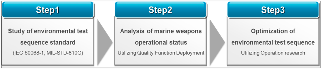
Figure 1.
Procedures of the environmental test sequence.
Figure 1.
Procedures of the environmental test sequence.
2. Standard Related Environmental Test
2.1. International Standard (IEC 60068-1)
A test sequence based on the environmental testing guidelines described in the International Electrotechnical Commission standard 60068-1 (IEC 60068-1) [21] was developed. The proposed test sequence incorporates the various principles and considerations of IEC 60068-1.
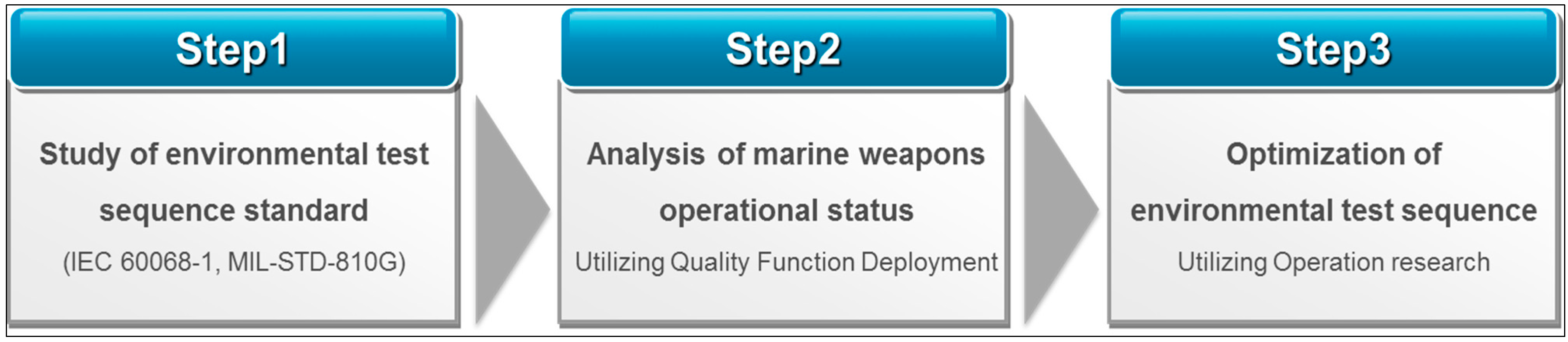
Four principles were applied to develop the test sequence as follows. The most and least severe tests should be carried out during the development testing. The tests that provide the most significant information, and the tests most likely to occur in practice should be carried out during the approval testing. The following test sequence is based on the principles and various considerations noted above: a cold test, dry-heat test, rapid change in temperature test, impact and vibration test, air-pressure test, damp heat-cycle test, steady-state test, corrosion test, and dust and sand test (see Figure 2). Rapid changes in temperature, impact, and vibration tests may cause mechanical stress, which could make the sample more sensitive to subsequent tests. Application of air-pressure and damp heat-cycle tests will reveal the influence of the preceding thermal and mechanical stress tests. Application of the dust and sand test may aggravate the effects of the preceding thermal and mechanical stress tests.

Figure 2.
Test sequence guideline.
Figure 2.
Test sequence guideline.
2.2. National Standard (MIL-STD-810G)
A test sequence based on the United States Military Standard 810G (MIL-STD-810G) [22] was also developed. Tests associated with environmental testing of electrical units include high-temperature, low-temperature, temperature shock, solar radiation (sunshine), rain, humidity, fungus, salt-fog, sand and dust, and immersion tests.
One testing approach to conserve the test-item life is to apply those tests that are perceived to be the least damaging, such as the high- and low-temperature tests, early in the test sequence. Another approach is to apply the tests that maximize the likelihood of disclosing synergistic effects. In this case, high- and low-temperature testing follows the dynamic tests, such as vibration and shock testing. The temperature shock test employs the test-item response characteristics, and performance information obtained from the high- and low-temperature tests better define the test conditions. Since contamination by fluids potentially has decontamination effects, this test was not performed prior to other climatic environmental tests. The solar radiation (sunshine) test applies to all stages. However, high temperatures or actinic effects could affect the material strength or dimensions, and therefore influence the results of subsequent tests, such as vibration testing. The effectiveness of determining the integrity of an enclosure is maximized if the rain test is performed after the dynamic tests.
Humidity testing may produce irreversible effects. Therefore, if humidity effects could influence the results of subsequent tests on the same item(s), humidity testing should be performed following those tests. For example, dynamic environments (vibration and shock) may be influenced by the results of humidity testing; thus, one should perform the dynamic tests prior to the humidity tests. In addition, because of the potentially unrepresentative combination of environmental effects, it is generally inappropriate to conduct humidity testing on test samples that were previously subjected to salt-fog, sand and dust, or fungus tests. If necessary, a fungus test should be performed before salt-fog, sand and dust, or humidity tests, because a heavy concentration of salt and moisture may influence the germinating fungus growth, and sand and dust can provide nutrients, thus leading to a false indication of the bio-susceptibility of the test item.
If the same test-item sample is used for more than one climatic test, it is usually recommend that the salt-fog test be conducted after the other climatic tests, because salt deposits can influence the results. As noted above, it is generally inappropriate to conduct salt-fog, fungus, and humidity tests on the same test samples, because the accumulation of effects from the three environments may be unrealistic. However, if it is necessary to do so, the salt-fog test should be performed after the fungus and humidity tests.
Sand and dust testing can severely abrade and/or leave a dust coating on the test samples, which could influence the results of other MIL-STD-810 tests, including the humidity, fungus, and salt-fog tests. Therefore, judgment should be used in determining where in the sequence of tests to apply the sand and dust testing. An explosive atmosphere test can be performed in the latter part of the test sequence based on the approach of maintaining the life of a sample in environments considered to be less detrimental. Because vibration, shock, and thermal stress can contort a sealed part and reduce the sealing efficiency, and a combustible atmosphere more easily ignites, vibration, shock, and temperature tests should be performed beforehand. The presence of dust in combination with other environmental parameters can induce corrosion or mold growth, and a warm humid environment can cause corrosion in the presence of chemically aggressive dust.
Two or more approaches can be used for immersion testing. One approach conserves the test-item life by first applying the least damaging environments. In this approach, the immersion test is generally performed prior to most other climatic tests. Another approach is to apply different environmental tests in a sequence that maximizes the likelihood of revealing sequential problems. In this approach, immersion testing should be considered both before and after the structural tests, such as shock and vibration testing, to aid in determining the resistance of the test item to dynamic tests.
Similarly, acoustic noise may induce stresses that influence the material performance under other environmental conditions, such as temperature, humidity, pressure, and electromagnetic fields, and should thus be performed in the early stages of the test sequence. The placement of the shock test in the sequence will depend upon the general availability of test samples and on the type of testing (i.e., whether the goal of the testing is developmental, qualification, or endurance). Normally, shock tests should be scheduled early in the test sequence, but after any vibration tests. Shocks usually occur after vibrations in practice, and shock testing without vibration is not meaningful.
A gunfire shock test may be performed, depending on whether the testing is for development, certification, or durability, and depending on the general usefulness of the test sample. This test is generally performed at the outset of the test sequence after the vibration, temperature, and mechanical shock tests. A ballistic shock test is usually assigned to the latter part of the test sequence, because it generally occurs during combat and at the end of the life cycle. This test can be considered independently of the other tests due to its unusual and special characteristics.
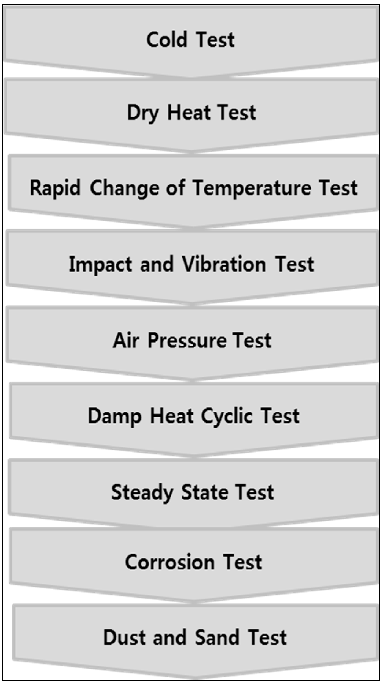
Table 1 summarizes each test and the required test sequence. The dynamic tests include vibration and shock tests, and the temperature test includes high and low temperatures. The climatic tests include solar radiation (sunshine), rain, humidity, fungus, salt-fog, immersion, and freeze/thaw tests, as well as a temperature test. Figure 3 illustrates several proposed test sequences based on the above suggestions. The tests can be performed in the following order: First, a vibration test, shock test, and high- and low-temperature test or humidity test; second, an immersion test and climatic test, and then a test involving contamination by fluids or a salt-fog test; and third, a fungus test or humidity test followed by a salt-fog test and sand and dust test. The third proposal is not recommended by MIL-STD-810G since it is the least feasible, but its sequence can be followed if necessary.

Table 1.
Description of the tests and test sequence.
| Before the test | Test | After the test |
|---|---|---|
| Dynamic test | High temperature | - |
| Dynamic test | Low temperature | - |
| - | Temperature shock | - |
| Climatic test | Contamination by fluids | |
| - | Solar radiation (sunshine) | - |
| - | Rain | - |
| Dynamic test | Humidity | - |
| - | Fungus | - |
| Climatic test, Fungus and humidity test | Salt fog | Sand and dust test |
| Salt fog | Sand and dust | - |
| Vibration, shock, temperature test | Explosive atmosphere | |
| Dynamic test | Immersion | Climatic, dynamic test |
| - | Acoustic noise | - |
| Vibration test | Shock | - |
| Vibration, shock, temperature test | Gunfire shock | - |
| - | Ballistic shock | - |
| - | Freeze/thaw | - |
| - | Mechanical vibrations of shipboard equipment | - |
Figure 3.
Proposed test sequences based on the national MIL-STD-810G standard.
Figure 3.
Proposed test sequences based on the national MIL-STD-810G standard.

3. Environmental Analysis in Operational State
Several recent accidents involving marine weapons include the following. In 2000, an explosion caused by the accidental discharge of a torpedo resulted in the sinking of a Russian nuclear-powered submarine during military training. All 118 people on board died in this accident. In 2008, a gas poisoning accident in a Russian nuclear-powered submarine occurred on a voyage due to an equipment malfunction. More than 20 people died, and 21 people were injured in the accident. In 2012, a torpedo on a Korean vessel mislaunched, and sank to the bottom of the sea without exploding due to a breakdown in the hydraulic equipment. In 2013, a North Korean naval battleship sank because sea waves caused a crack in the vessel; 71 people were killed in this accident.
Feasible operational scenarios have been designed to prevent such persistent accidents involving marine weapons. These scenarios can be divided into the following categories: engine ignition at the start of operations; operation at sea; launch of a torpedo or missile; bombardment from the surroundings; transportation to storage; and storing marine weapons when it rains, and at low or high temperatures. To evaluate the degree of influence of each environmental stress factor of the operational scenarios, the environmental stresses at sea (marine environmental stresses) were selected on the basis of MIL-STD-810. According to the research findings, the environmental factors can be grouped into the inductive environment and the natural exposure environment; the factors differ depending on whether a torpedo or missile is considered. The inductive environment of a vessel consists of wave-induced vibration (sinusoidal), engine-induced vibration, acoustic noise, wave slam shock, mine/blast shock, weapon firing shock, an explosive atmosphere, electromagnetic interference, and increased pressure (submarine). The natural exposure environment consists of high temperatures (dry/humid), low temperatures/freezing, thermal shock (storage to use), rain, salt fog, solar radiation, fungus growth, and chemical attack. In addition to the tests required for actual operations, tests while in storage account for additional sand and dust stresses. The inductive environment of a torpedo or missile consists of the launch acceleration, handling/launch shock, engine-induced vibration, acoustic noise, pyrotechnic shock, explosive atmosphere, and electromagnetic interference, whereas the natural exposure environment consists of immersion and thermal shock. Here, the testable items for the environmental factors applicable to a vessel, torpedo, or missile were based on the environmental factors described in MIL-STD-810G. The degree of influence of an operational scenario was estimated using a scale consisting of one, three, or five in a one-phase QFD analysis.
The thermal shock environmental stress as an engine starts up for operation is caused by the engine vibration, wave-inducing vibration, and acoustic noise, as well as the generated heat. Under the continuous acoustic noise generated during operation at sea, exposure to wave slam shock, solar radiation, and fungus is likely. Because the weapons are operated at sea, they will be seriously affected by salt fog and the immersion environment. Torpedo and missile launches generate waves that lead to vibration and acoustic noise, as well as launch shocks. They will also experience an explosive atmosphere and high temperature and thermal shock stresses, and will be affected by launch acceleration and immersion. If they are exposed to bombardment, they may be affected by acoustic noise, mine/blast shock, an explosive atmosphere, thermal shock, and immersion. When marine weapons are transported to a storage space, they will be slightly affected by engine-induced vibration, wave slam shock, solar radiation, chemical attack, and sand/dust, and will be more affected by salt fog or immersion. They will be affected by environmental stresses when it rains or the temperature is high or low, depending on the climate. Moreover, they will be affected by salt fog, fungus growth, immersion, and sand/dust during storage.
Such operational scenarios for marine weapons, and the effects of the environmental stress factors are listed in the Table 2 below.
Table 2.
One-phase QFD analysis of operational scenarios and environmental stresses.
| Environmental Stress | wave induced vibration | engine induced vibration | acoustic noise | wave slam shock | mine/blast shock | weapon firing shock | explosive atmosphere | high temperature | low temperature/freezing | thermal shock | rain | salt fog | solar radiation | fungus growth | chemical attack | launch acceleration | immersion | Sand/dust | |
|---|---|---|---|---|---|---|---|---|---|---|---|---|---|---|---|---|---|---|---|
| Turning on an engine to start operation | 1 | 3 | 3 | 1 | 1 | ||||||||||||||
| Operation at sea | 1 | 1 | 5 | 1 | 1 | 3 | 5 | 1 | |||||||||||
| Launching a torpedo or missile | 3 | 5 | 5 | 3 | 1 | 3 | 5 | 5 | 5 | ||||||||||
| Exposure to bombardment | 3 | 5 | 5 | 5 | 1 | ||||||||||||||
| Transportation to storage place | 1 | 1 | 5 | 1 | 1 | 3 | 1 | ||||||||||||
| Raining | 3 | 5 | 1 | 5 | 5 | 3 | 3 | 3 | |||||||||||
| Low temperature | 3 | 5 | 5 | 5 | |||||||||||||||
| High temperature | 5 | 5 | 5 | 5 | |||||||||||||||
| Storage in the storage place | 5 | 3 | 3 | 5 | |||||||||||||||
| Total degree of influence | 10 | 9 | 12 | 7 | 5 | 5 | 8 | 6 | 9 | 11 | 5 | 30 | 7 | 12 | 7 | 5 | 20 | 8 | |
To carry out the two-phase QFD analysis on the test factors based on the one-phase QFD analysis of the operational scenarios and environmental stress factors, the test items described in MIL-STD-810G were considered to determine which test would be most suitable for investigating the environmental stresses. For example, a mechanical vibration test of the shipboard equipment is required to examine the wave-induced and engine-induced vibration stresses, a shock test is required to analyze the wave slam shock stress, and a high temperature and humidity test is required to estimate the high-temperature stresses. The tests for the different environmental factors are listed in Table 3.
Table 3.
Test factors suitable for each type of environmental stress.
| Types of Environment | Vessel | Torpedo or Missile | ||
|---|---|---|---|---|
| Environmental factor | Test item | Environmental factor | Test item | |
| Induced Environment | wave induced vibration (sinusoidal) | mechanical vibrations of shipboard equipment | launch acceleration | gunfire shock |
| engine induced vibration | mechanical vibrations of shipboard equipment | handling/launch shock | gunfire shock | |
| acoustic noise | acoustic noise | engine induced vibration | mechanical vibrations of shipboard equipment | |
| wave slam shock | shock | acoustic noise | acoustic noise | |
| mine/blast shock | ballistic shock | pyrotechnic shock | temperature shock | |
| weapon firing shock | gunfire shock | explosive atmosphere | explosive atmosphere | |
| explosive atmosphere | explosive atmosphere | electromagnetic interference | ||
| electromagnetic interference | ||||
| increased pressure(submarine) | ||||
| Natural Environment | high temperature(dry/humid) | high temperature and humidity | immersion | immersion |
| low temperature/freezing | low temperature and freeze and thaw | thermal shock | temperature shock | |
| thermal shock(storage to use) | temperature shock | |||
| rain | rain and immersion | |||
| salt fog | salt fog | |||
| solar radiation | solar radiation and high temperature | |||
| fungus growth | fungus and humidity | |||
| chemical attack | immersion and contamination by fluids | |||
| sand/dust | sand and dust | |||
The two-phase QFD analysis was used to evaluate the degree of influence of a test item based on an assigned environmental stress factor of one, three, or five. According to the research findings, the salt-fog test (150) showed the highest degree of influence, followed by the immersion test (136), mechanical vibration of shipboard equipment test (95), fungus test (60), acoustic noise test (60), and temperature shock test (55). The analysis results are listed in Table 4.
Table 4.
Two-phase QFD analysis of environmental stress and test.
| Test Item | high temperature | low temperature | temperature shock | contamination by fluids | solar radiation | rain | humidity | fungus | salt fog | sand and dust | explosive atmosphere | immersion | acoustic noise | shock | gunfire shock | ballistic shock | freeze and thaw | mechanical vibrations of shipboard equipment | |
|---|---|---|---|---|---|---|---|---|---|---|---|---|---|---|---|---|---|---|---|
| wave induced vibration (sinusoidal) | 10 | 5 | |||||||||||||||||
| engine induced vibration | 9 | 5 | |||||||||||||||||
| acoustic noise | 12 | 5 | |||||||||||||||||
| wave slam shock | 7 | 5 | |||||||||||||||||
| mine/blast shock | 5 | 5 | |||||||||||||||||
| weapon firing shock | 5 | 5 | |||||||||||||||||
| explosive atmosphere | 8 | 5 | |||||||||||||||||
| high temperature (dry/humid) | 6 | 5 | 3 | ||||||||||||||||
| low temperature/freezing | 9 | 3 | 5 | ||||||||||||||||
| thermal shock | 11 | 5 | |||||||||||||||||
| rain | 5 | 5 | 3 | ||||||||||||||||
| salt fog | 30 | 5 | |||||||||||||||||
| solar radiation | 7 | 1 | 5 | ||||||||||||||||
| fungus growth | 12 | 1 | 5 | ||||||||||||||||
| chemical attack | 7 | 1 | 3 | ||||||||||||||||
| launch acceleration | 5 | 5 | |||||||||||||||||
| immersion | 20 | 5 | |||||||||||||||||
| sand/dust | 8 | 5 | |||||||||||||||||
| Total degree of influence | 37 | 27 | 55 | 7 | 35 | 25 | 30 | 60 | 150 | 40 | 40 | 136 | 60 | 35 | 50 | 25 | 45 | 95 | |
4. Environmental Test Sequence Optimization
We determined the optimal environmental test sequence suitable for each component according to the influence score. This study was performed based on the test time per item, using the test items described in MIL-STD-810G. The test items and test times from MIL-STD-810G are listed in Table 5. If the test time was not described in MIL-STD-810G or was not accurate, it was determined by referring to the environmental test for an electrical unit described in IEC 60068-1, and the test standard for an automatic electrical unit described in the International Standards Organization (ISO) 16750 standard. For the explosive atmosphere test, whose test time could not be estimated, we assumed a test time of 10 h. The times of the gunfire shock and ballistic shock tests were assumed to be the same as the test time of the shock test. The influence score for each test item was based on the two-phase QFD analysis results. Five points were given for the first to the sixth rank, and three points were given from the seventh to the 12th rank; the rest were assigned one point. According to our study of MIL-STD-810G, because a ballistic shock test, with its unusual and peculiar characteristics, is independent of the other tests and could be assigned to a separate test leg, it was excluded from the integer programming. The test items, test times, testing time references, and influence scores are listed in Table 5. The variables and constants used in the integer programming are listed in Table 6.
Table 5.
Test items, test times, references, and influence scores [22,23,24,25].
| No | Test item | Time for test (hour) | References | Influence score |
|---|---|---|---|---|
| 1 | high temperature | 168 | MIL-STD-810G | 3 |
| 2 | low temperature | 72 | MIL-STD-810G | 1 |
| 3 | temperature shock | 452.4 | ISO 16750-4 | 5 |
| 4 | contamination by fluids | 24 | MIL-STD-810G | 1 |
| 5 | solar radiation | 240 | MIL-STD-810G | 3 |
| 6 | rain | 2 | IEC 60068-2-18 | 1 |
| 7 | humidity | 720 | MIL-STD-810G | 1 |
| 8 | fungus | 672 | MIL-STD-810G | 5 |
| 9 | salt fog | 96 | MIL-STD-810G | 5 |
| 10 | sand and dust | 12 | MIL-STD-810G | 3 |
| 11 | explosive atmosphere | 10 | Assumption | 3 |
| 12 | immersion | 1 | MIL-STD-810G | 5 |
| 13 | acoustic noise | 0.5 | MIL-STD-810G | 5 |
| 14 | shock | <1 | IEC 60068-2-27 | 3 |
| 15 | gunfire shock | <1 | Presumption | 3 |
| 16 | freeze and thaw | 80 | MIL-STD-810G | 3 |
| 17 | mechanical vibrations of shipboard equipment | 6 | MIL-STD-810G | 5 |
| 18 | ballistic shock | <1 | Presumption | 1 |
Table 6.
Definitions of variables and constants.
| Notation | Description | |
|---|---|---|
| Variables | i | Test items |
| j | Test leg | |
| xij | Whether test i is assigned to leg j (0 or 1) | |
| ti | Time for test i (hour) | |
| tmax | Test time of the longest leg (hour) | |
| Zi | Influence score per test according to its degree of influence | |
| Constants | n | Number of test items |
| m | Maximum number of tests per leg | |
| tlimit | Maximum test time (hour) | |
| S | Minimum influence score of a sample | |
The objective function and constraints were established and modeled based on the variables and constants listed in Table 6. The objective function was formulated to minimize the total test time within a specified test leg by determining the optimum number of test legs. The constraints ensured that all tests were conducted more than once, but in less than three of the legs. A boundary equation was established to find the maximum test time of all of the legs. To obtain different optimal test sequences according to the influence score, all of the legs were set higher than the established minimum influence score. In addition, parts of test sequences proposed in previous studies of environmental test standards were applied. For example, a salt-fog (x9j) test and sand and dust test (x10j) should be performed in the same leg, and a vibration test (x14j) and shock test (x18j) should also be performed in the same leg. The established objective function and constraints were as follows.
The integer programming was performed using ILOG OPL based on the modeled formula. The number of legs and the influence score were used as the analysis variables to propose the optimal test sequence that minimized the test time. The number of legs was set to 5, 6, or 7, and the influence scores were 0, 2, 4, 6, 8, …, 20. The analysis results for each leg and each influence score are listed in Table 7.
Table 7.
Results of the integer programming.
| Predetermined values | Result values | ||||||
|---|---|---|---|---|---|---|---|
| No | Number of Leg | Minimum influence score | Number of Leg | Influence score | Time (hour) | ||
| Min | Max | Min | Max | ||||
| 1 | 5 | 0 | 17 | 1 | 35 | 207.5 | 720 |
| 2 | 2 | 17 | 5 | 30 | 207 | 720.5 | |
| 3 | 4 | 17 | 5 | 30 | 207 | 720.5 | |
| 4 | 6 | 18 | 6 | 25 | 169 | 720.5 | |
| 5 | 8 | 24 | 11 | 20 | 452 | 721.5 | |
| 6 | 10 | 23 | 10 | 19 | 361 | 721.5 | |
| 7 | 12 | 23 | 14 | 22 | 171.5 | 722.5 | |
| 8 | 14 | 27 | 14 | 34 | 638.4 | 722.5 | |
| 9 | 16 | 27 | 17 | 19 | 259.5 | 723.5 | |
| 10 | 18 | 28 | 18 | 21 | 374 | 725.5 | |
| 11 | 20 | 30 | 20 | 22 | 270.5 | 729.5 | |
| 12 | 6 | 0 | 17 | 1 | 35 | 207.5 | 720 |
| 13 | 2 | 17 | 5 | 25 | 1 | 720.5 | |
| 14 | 4 | 17 | 5 | 25 | 1 | 720.5 | |
| 15 | 6 | 32 | 6 | 34 | 191.5 | 720.5 | |
| 16 | 8 | 21 | 8 | 26 | 416 | 721.5 | |
| 17 | 10 | 24 | 11 | 17 | 187 | 721.5 | |
| 18 | 12 | 27 | 12 | 19 | 127 | 722.5 | |
| 19 | 14 | 27 | 14 | 18 | 560.9 | 722.5 | |
| 20 | 16 | 30 | 16 | 20 | 188.5 | 723.5 | |
| 21 | 18 | 35 | 18 | 22 | 303 | 725.5 | |
| 22 | 20 | 38 | 20 | 23 | 357.5 | 729.5 | |
| 23 | 7 | 0 | 17 | 1 | 38 | 266 | 720 |
| 24 | 2 | 17 | 3 | 25 | 1 | 720.5 | |
| 25 | 4 | 17 | 5 | 20 | 1 | 720.5 | |
| 26 | 6 | 18 | 6 | 12 | 31 | 720.5 | |
| 27 | 8 | 29 | 9 | 18 | 145 | 721.5 | |
| 28 | 10 | 27 | 10 | 25 | 201 | 721.5 | |
| 29 | 12 | 26 | 12 | 15 | 243.5 | 722.5 | |
| 30 | 14 | 32 | 14 | 18 | 92 | 722.5 | |
| 31 | 16 | 35 | 16 | 18 | 90 | 723.5 | |
| 32 | 18 | 43 | 18 | 23 | 567.4 | 725.5 | |
| 33 | 20 | 44 | 20 | 22 | 539.9 | 729.5 | |
According to the findings, the testing time steadily increased from 720 h to 795.5 h because numerous tests were conducted in one leg with increasing influence score, regardless of the number of legs. The minimum testing time did not fall below 720 h because the testing time of an immersion test, which takes the longest time, is 720 h. The number of test items in the optimal test sequence increased with the influence score and the number of legs, because all of the legs had to be higher than the specified influence score.
The optimal test sequence was proposed based on the results for 1, 11, and 22 legs in Table 7 (see Table 8, Table 9 and Table 10). The ballistic shock test, which was excluded from this research and has to be performed independently of the other tests, was included in the legs. The number of legs in Table 8 and Table 9 is 5, but since the influence score of Table 9 is greater than that of Table 8, more test items and longer test times were required. In addition, the influence score of both Table 9 and Table 10 is 20, but since the number of legs in Table 10 is more than that in Table 9, more test items are required for the same testing time. Thus, a test designer can propose an optimal test sequence by setting the number of legs and the influence score according to various conditions, such as the processing time and cost.
Table 8.
Results for five legs and an influence score of 0.
| Leg No. | Leg 1 | Leg 2 | Leg 3 | Leg 4 | Leg 5 | Leg 6 |
|---|---|---|---|---|---|---|
| Test item | salt fog | fungus | temperature shock | humidity | high temperature | ballistic shock |
| sand and dust | low temperature | |||||
| explosive atmosphere | contamination by fluids | |||||
| immersion | solar radiation | |||||
| acoustic noise | rain | |||||
| shock | ||||||
| gunfire shock | ||||||
| freeze and thaw | ||||||
| mechanical vibrations of shipboard equipment | ||||||
| The total time per Leg | 207.5 | 672 | 452.4 | 720 | 506 | 1 |
| The total influence score per Leg | 35 | 5 | 5 | 1 | 9 | 1 |
Table 9.
Results for five legs and an influence score of 20.
| Leg No. | Leg 1 | Leg 2 | Leg 3 | Leg 4 | Leg 5 | Leg 6 |
|---|---|---|---|---|---|---|
| Test item | temperature shock | humidity | rain | low temperature | high temperature | ballistic shock |
| contamination by fluids | immersion | fungus | salt fog | salt fog | ||
| solar radiation | acoustic noise | explosive atmosphere | sand and dust | sand and dust | ||
| immersion | shock | acoustic noise | explosive atmosphere | explosive atmosphere | ||
| shock | gunfire shock | shock | acoustic noise | gunfire shock | ||
| mechanical vibrations of shipboard equipment | mechanical vibrations of shipboard equipment | gunfire shock | freeze and thaw | freeze and thaw | ||
| The total time per Leg | 724.4 | 729.5 | 686.5 | 270.5 | 367 | 1 |
| The total influence score per Leg | 22 | 22 | 20 | 20 | 20 | 1 |
Table 10.
Results for six legs and an influence score of 20.
| Leg No. | Leg 1 | Leg 2 | Leg 3 | Leg 4 | Leg 5 | Leg 6 | Leg 7 |
|---|---|---|---|---|---|---|---|
| Test item | contamination by fluids | humidity | solar radiation | contamination by fluids | high temperature | temperature shock | ballistic shock |
| rain | immersion | rain | solar radiation | low temperature | salt fog | ||
| fungus | acoustic noise | salt fog | salt fog | contamination by fluids | sand and dust | ||
| explosive atmosphere | shock | sand and dust | sand and dust | rain | shock | ||
| immersion | gunfire shock | explosive atmosphere | shock | explosive atmosphere | mechanical vibrations of shipboard equipment | ||
| acoustic noise | mechanical vibrations of shipboard equipment | immersion | mechanical vibrations of shipboard equipment | acoustic noise | |||
| gunfire shock | gunfire shock | ||||||
| freeze and thaw | |||||||
| The total time per Leg | 709.5 | 729.5 | 362 | 379 | 357.5 | 567.4 | 1 |
| The total influence score per Leg | 20 | 22 | 23 | 20 | 20 | 21 | 1 |
5. Conclusions
With the recent advances in information and communication technology and long-distance weaponry, the need for marine weapons, as well as ground-force and air-force weapons, has increased in response to the diverse threats faced by the navy. However, because environmental tests of marine weapons are typically performed in a single environment, reproduction and prevention of failures are difficult. Therefore, to reproduce field failures that are undetected by current reliability tests, both international and national standards for environmental testing of electrical units were examined, and guidelines were proposed for the test sequence, including a recommendation to perform a high-temperature test after a low-temperature test, and to conduct a shock test after a vibration test. The need for multi-environment tests was recognized from accidents, such as the sinking of marine weapons and mislaunches of torpedoes. General operational scenarios were suggested. By performing a two-phase QFD analysis of the relationships between operational scenarios and environmental stresses factors based on an international standard for an environmental test sequence, the test items required to operate marine weapons were determined. A salt-fog test had the greatest effect on marine weapons, followed by an immersion test and a mechanical vibration of a shipboard equipment test. Based on the degree of importance of such test items, the influence score necessary for a study of the optimal test sequence was evaluated on a scale of one, three, and five. Integer programming using ILOG OPL was conducted to determine an environmental test sequence with the minimum test time based on the known times of each test.
According to the number of test legs and the influence score determined by our analysis, the minimum test time and number of test items increased with the influence score, regardless of the number of legs. In addition, if the number of legs increased, more tests were required, even at the same influence score. Three examples of optimal test sequences were proposed. Using this process, a test designer can determine the optimal test sequence according to various requirements, such as the processing time and cost, by setting the number of legs and the influence score.
Acknowledgments
This work was supported by Basic Science Research Program through the National Research Foundation of Korea (NRF) funded by the Ministry of Education, Science and Technology (2013R1A1A1009816).
Author Contributions
Yong Soo Kim contributed to the research design and writing the manuscript. Jung Ho Yang carried out related works, failure analysis and quality function deployment. In addition, both of the authors proposed the optimization models and environmental test sequences of marine weapons.
Conflicts of Interest
The authors declare no conflict of interest.
References
- Rebak, R.B.; Day, S.D.; Lian, T.; Hailey, P.D.; Farmer, J.C. Environmental testing of iron-based amorphous alloys. Metall. Mater. Trans. A 2008, 39, 225–234. [Google Scholar]
- Catelani, M.; Ciani, L. Experimental tests and reliability assessment of electronic ballast system. Microelectron. Reliab. 2012, 52, 1833–1836. [Google Scholar]
- Firor, K.; Hogan, S. Environmental testing of single-crystal silicon solar cells with screen-printed silver contacts. IEEE Trans. Reliab. 1982, 31, 270–275. [Google Scholar] [CrossRef]
- Hoang, B.; Wong, F.K.; Corey, R.L.; Gardiner, G.; Funderburk, V.V.; Gahart, R.L.; Wright, K.H.; Schneider, T.A.; Vaughn, J.A. Combined space environmental exposure test of multijunction GaAs/Ge solar array coupons. IEEE Trans. Plasma Sci. 2012, 40, 324–333. [Google Scholar]
- Lee, S.B.; Jung, M.S.; Lee, H.Y.; Kang, T.; Joo, Y.C. Effect of bias voltage on the electrochemical migration behaviors of Sn and Pb. IEEE Trans. Device Mater. Reliab. 2009, 9, 483–488. [Google Scholar] [CrossRef]
- Liţă, I.; Vişan, D.A.; Cioc, I.B. Virtual Instrumentation Application for Vibration Analysis in Electrical Equipments Testing. In Proceedings of the 33rd International Spring Seminar on Electronics Technology (ISSE), Warsaw, Poland, 12–16 May 2010; pp. 216–219.
- Maier, D.; Alomari, M.; Grandjean, N.; Carlin, J.F.; di Forte-Poisson, M.A.; Dua, C.; Chuvilin, A.; Troadec, D.; Gaquière, C.; Kaiser, U.; et al. Testing the temperature limits of GaN-based HEMT devices. IEEE Trans. Device Mater. Reliab. 2010, 10, 427–436. [Google Scholar]
- Su, P.; Howell, J.; Chopin, S. A statistical study of Sn whisker population and growth during elevated temperature and humidity tests. IEEE. Trans. Electron. Packag. Manuf. 2006, 29, 246–251. [Google Scholar] [CrossRef]
- Da Silva, D.A.; da Costa, E.C.M.; de Franco, J.L.; Antonionni, M.; de Jesus, R.C.; Abreu, S.R.; Lahti, K.; Mei, L.H.I.; Pissolato, J. Reliability of directly-molded polymer surge arresters: Degradation by immersion test versus electrical performance. Int. J. Electric. Power Energy Syst. 2013, 53, 488–498. [Google Scholar] [CrossRef]
- Ha, S.S.; Ha, S.O.; Yoon, J.W.; Kim, J.W.; Ko, M.K.; Kim, D.G.; Kim, S.J.; Hong, T.H.; Jung, S.B. Solder joint reliability in flip chip package with surface treatment of ENIG under thermal shock test. Met. Mater. Int. 2009, 15, 655–660. [Google Scholar] [CrossRef]
- Rajalakshmi, N.; Pandian, S.; Dhathathreyan, K.S. Vibration tests on a PEM fuel cell stack usable in transportation application. Int. J. Hydrog. Energ. 2009, 34, 3833–3837. [Google Scholar] [CrossRef]
- Qi, H.; Osterman, M.; Pecht, M. A rapid life-prediction approach for PBGA solder joints under combined thermal cycling and vibration loading conditions. IEEE Trans. Compon. Packag. Technol. 2009, 32, 283–292. [Google Scholar] [CrossRef]
- Matkowski, P.; Urbanski, K.; Falat, T.; Felba, J.; Zaluk, Z.; Zwierta, R.; Dasgupta, A.; Pecht, M. Application of FPGA Units in Combined Temperature Cycle and Vibration Reliability Tests of Lead-Free Interconnections. In Proceedings of the 2nd Electronics System-Integration Technology Conference (ESTC), Greenwich, UK, 1–4 September 2008; pp. 1375–1380.
- Qi, H.; Osterman, M.; Pecht, M. Modeling of combined temperature cycling and vibration loading on pbga solder joints using an incremental damage superposition approach. IEEE Trans. Adv. Packag. 2008, 31, 463–472. [Google Scholar]
- Qi, H.; Ganesan, S.; Osterman, M.; Pecht, M. Accelerated Testing and Finite Element Analysis of PBGA under Multiple Environmental Loadings. In Proceedings of the International Conference on Business of Electronic Product Reliability and Liability, Shanghai, China, 27–30 April 2004; pp. 99–106.
- Chen, Y.S.; Lee, Y.S.; Lin, Y.C. Comparison Among Individual Thermal Cycling, Vibration Test and the Combined Test for the Life Estimation of Electronic Components. In Proceedings of the International Microsystems, Packaging, Assembly and Circuits Technology Conference (IMPACT), Taipei, Taiwan, 19–21 October 2011; pp. 385–388.
- Yoon, S.; Jang, C.; Han, B. Nonlinear stress modeling scheme to analyze semiconductor packages subjected to combined thermal and hygroscopic loading. J. Electron. Packag. 2008, 130, 024502. [Google Scholar] [CrossRef]
- Falat, T.; Felba, J.; Matkowski, P.; Urbanski, K.; Zaluk, Z. Combined System for Testing of Joints in Microelectronic Packaging under Thermal Cycling, Humidity and Vibration Loading. In Proceedings of the 29th International Conference of IMAPS, Koszalin, Poland, 19–21 September 2005.
- Chan, H. Accelerated Qualification of Electronic Assemblies under Combined Temperature Cycling and Vibration Environments: Is Miner’s Hypothesis Valid? IEEE Press: Hoboken, NJ, USA, 2001; pp. 189–202. [Google Scholar]
- Miner, M.A. Cumulative Damage in Fatigue. J. Appl. Mech. 1945, 12, A159–A164. [Google Scholar]
- Environmental Testing—Part 1: General and Guidance, IEC 60068-1; IEC: Geneva, Switzerland, 30 June 1988.
- Environmental Engineering Considerations and Laboratory Tests; MIL-STD-810G; U.S. Department of Defense: Washington, DC, USA, 31 October 2008.
- Environmental Testing—Part 2-18: Tests—Test R and Guidance: Water, IEC 60068-2-18; IEC: Geneva, Switzerland, 18 October 2000.
- Environmental Testing—Part 2-27: Tests—Test Ea and Guidance: Shock, IEC 60068-2-27; IEC: Geneva, Switzerland, 15 June 1987.
- Road Vehicles-Environmental Conditions and Testing for Electrical and Electronic Equipment—Part 4: Climatic Loads, ISO 16750-4; ISO: Geneva, Switzerland, 15 April 2010.
© 2014 by the authors; licensee MDPI, Basel, Switzerland. This article is an open access article distributed under the terms and conditions of the Creative Commons Attribution license (http://creativecommons.org/licenses/by/4.0/).