Article

Change Capsule Network for Optical Remote Sensing Image Change Detection

1
Aerospace Information Research Institute, Chinese Academy of Sciences, Beijing 100190, China
2
School of Electronic, Electrical and Communication Engineering, University of Chinese Academy of Sciences, Beijing 100190, China
3
Key Laboratory of Network Information System Technology (NIST), Aerospace Information Research Institute, Chinese Academy of Sciences, Beijing 100190, China
4
University of Chinese Academy of Sciences, Beijing 100190, China
*
Author to whom correspondence should be addressed.
Remote Sens. 2021, 13(14), 2646; https://doi.org/10.3390/rs13142646
Submission received: 13 May 2021 / Revised: 27 June 2021 / Accepted: 2 July 2021 / Published: 6 July 2021

Abstract

:
Change detection based on deep learning has made great progress recently, but there are still some challenges, such as the small data size in open-labeled datasets, the different viewpoints in image pairs, and the poor similarity measures in feature pairs. To alleviate these problems, this paper presents a novel change capsule network by taking advantage of a capsule network that can better deal with the different viewpoints and can achieve satisfactory performance with small training data for optical remote sensing image change detection. First, two identical non-shared weight capsule networks are designed to extract the vector-based features of image pairs. Second, the unchanged region reconstruction module is adopted to keep the feature space of the unchanged region more consistent. Third, vector cosine and vector difference are utilized to compare the vector-based features in a capsule network efficiently, which can enlarge the separability between the changed pixels and the unchanged pixels. Finally, a binary change map can be produced by analyzing both the vector cosine and vector difference. From the unchanged region reconstruction module and the vector cosine and vector difference module, the extracted feature pairs in a change capsule network are more comparable and separable. Moreover, to test the effectiveness of the proposed change capsule network in dealing with the different viewpoints in multi-temporal images, we collect a new change detection dataset from a taken-over Al Udeid Air Basee (AUAB) using Google Earth. The results of the experiments carried out on the AUAB dataset show that a change capsule network can better deal with the different viewpoints and can improve the comparability and separability of feature pairs. Furthermore, a comparison of the experimental results carried out on the AUAB dataset and SZTAKI AirChange Benchmark Set demonstrates the effectiveness and superiority of the proposed method.

1. Introduction

Change detection is the process of identifying differences in the state of an object or phenomenon by observing it at different times [1]. As one of the important technologies for remote sensing image analysis, change detection has played an important role in the military and in civilian life, such as military strike effect evaluation [2,3,4], land use [5,6,7,8,9], and natural disaster evaluation [10,11,12,13].
Recently, deep learning (DL) has been widely applied to the field of change detection [14,15,16,17,18,19] thanks to its simple process, strong feature representation ability, and excellent application performance. However, there are still many challenges in change detection. First, DL-based methods usually require a large number of labeled samples to optimize the network. However, the available open-labeled datasets for remote sensing change detection are extremely scarce and predominantly very small compared to other remote sensing image-interpretation fields [20]. For example, The Vaihingen dataset, which is widely used in remote sensing image classification [21,22], only contains 33 patches, and each pair of images is about 1900 × 2500 pixels. The effective sample size of Vaihingen is about 1.5 × 10 8 . The SZTAKI AirChange Benchmark Set [23,24], which is extensively used to evaluate the performance of change detection algorithms [14,15,16,18,25], is composed of 13 aerial image pairs with size of 952 × 640 pixels. Therefore, the effective sample size of SZTAKI is only about 7.9 × 10 6 . In comparison, the data size of change detection is more than 100 times smaller than that of the remote sensing image-classification dataset. Second, the image pairs or image sequences used for change detection are often obtained from different viewpoints [26,27,28,29]. In other words, it is difficult to capture a scene from similar viewpoints every time in remote sensing change detection. As shown in Figure 1, the buildings were shot at different times. Due to the different viewpoints, buildings have different shadows even if the image pair has been registered, which makes the comparison of image pairs more difficult. In order to alleviate the problems caused by different viewpoints, Sakurada et al. [26] designed a dense optical flow-based change detection network. Palazzolo et al. [30] relied on 3D models to identify scene changes by re-projecting images onto one another. Park et al. [27] presented a novel dual dynamic attention model to distinguish different viewpoints from semantic changes. Therefore, if the algorithms do not pay attention to the viewpoints, the result of the change detection is affected. Finally, the similarity measurement method of existing change detection methods is relatively simple. The study of similarity measurement in change detection has a long history. Traditional similarity measurement methods include image difference, image ratio, and change vector analysis (CVA) [31]. For DL-based methods, similarity measurement also plays an important role in improving the performance of model, such as the euclidean distance used in [14], the improved triplet loss function applied in [15], the difference skip connections adopted in [25], and the feature space loss designed in [32]. Similarity measurement is one of the important factors affecting the separability of sample pairs in change detection. It is beneficial to improve the performance of change detection to make sufficient and effective comparison of the features between sample pairs.
To deal with the small training data size in change detection datasets, some scholars chose unsupervised methods [16,33,34]. These methods did not require labeled training samples, but the performance of these algorithms could be improved. To cope with this problem, Xu et al. [
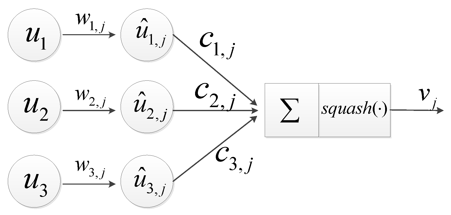
18] took advantages of the capsule network [35] and designed the pseudo-siamese capsule network. Siamese network has two branches in the network that share exactly the same architecture and the same set of weights. For pseudo-siamese, it has two identical branches but the weights of two branches are not shared. The capsule network used vectors for feature extraction and dynamic routing technology for features aggregation. As shown in much existing literature [35,36,37], the capsule network could use less training samples to reach the comparable performance than traditional convolutional neural networks (CNN). Moreover, the pseudo-siamese capsule network achieved satisfactory results on small open-labeled remote sensing change detection datasets, which confirmed that a capsule network was very suitable for change detection.
Unfortunately, the pseudo-siamese network still has some shortcomings. First, the pseudo-siamese capsule network [18] did not analyze the experimental results of the image pairs that were obtained from different viewpoints. Vector-based features and the dynamic routing technology in a capsule network are beneficial to the capsule network when dealing with the pose information (e.g., translation, rotation, viewpoint, and scale). In other words, the pseudo-siamese capsule network may alleviate the problem caused by different viewpoints in image pairs to some degree. It may be limited by the open dataset in which the problem of different viewpoints is not obvious and for which the pseudo-siamese capsule network did not investigate thoroughly in the experiments. Second, the weights of the two branches in the pseudo-siamese network were not shared in order to maintain the flexibility of the model [38], which may cause feature space offset. Therefore, the features that were extracted by the pseudo-siamese network were uncomparable. Finally, the extracted features were directly concatenated in the pseudo-siamese capsule network, which led to insufficient features comparison.
In order to alleviate the problems mentioned above, we carried out the following works. First, the AUAB dataset in which the sequence images are different in terms of illumination, season, weather, and viewpoint was collected from the Google Earth. Second, the reconstruction module on an unchanged region was designed. As a regularization method, this module drives the network to maintain the feature consistency on an unchanged region, which keeps the comparability between feature pairs. Finally, in order to make similarity measuring more efficient, the vector-based features output by the capsule network were compared for both direction and length in the forms of vector cosine and vector difference, which can alleviate the insufficient feature comparison in the pseudo-siamese capsule network.
The main contributions of this paper are summarized as follows:
  • This paper proposes a novel change capsule network for optical remote sensing image change detection. Compared with other DL-based change detection methods, the proposed change capsule network has good performance and robustness.
  • In order to make the extracted feature pairs in a change capsule network more comparable and separable, this paper designs an unchanged region reconstruction module and a vector cosine and vector difference module, respectively.
  • The AUAB dataset, which simulates practical applications, is collected to further analyze the viewpoints in change detection. Moreover, experiments on the AUAB dataset and the SZTAKI dataset show the effectiveness and robustness of the proposed method.
The rest of this paper is organized as follows. The background of the proposed method is introduced in Section 2, and Section 3 introduces the proposed method in detail. In Section 4, the dataset and present experimental results are described to validate the effectiveness of the proposed method. In Section 5, we discuss the results of the proposed method. Finally, the conclusion of this paper are drawn in Section 6.

2. Background

2.1. Capsule Network

Sabour et al. [35] introduced the idea of a capsule network. Different from the scalar-based feature in CNN, the feature extracted by the capsule network is a vector. The length of the vector represents the probability that the entity exists, and its orientation represents the instantiation parameters. Furthermore, the capsule network replaced the pooling layer used in convolutional networks with dynamic routing technology because the pooling layer may lose some information. As shown in much existing literature [18,35,36,37], a capsule network could use less training samples to reach comparable performance to that of a traditional CNN. Furthermore, a capsule network could better deal with the pose information (e.g., translation, rotation, viewpoint, and scale). It is worth noting that the image pairs or image sequences used for change detection are often obtained from different viewpoints. Therefore, a capsule network may alleviate the problem caused by different viewpoints in the field of remote sensing change detection.
Let the input of the capsule layer be a vector u i , and use the matrix w i , j to perform affine transformation on the input vector:
u ^ i , j = w i , j u i
Then, perform a weighted summation on the output of the affine transformation:
s j = i c i , j u ^ i , j
where c i , j is updated using the dynamic routing algorithm. The output vectors in capsule network are computed using a nonlinear squashing function:
v j = s j 2 1 + s j 2 s j s j
It can be seen from Equation (3) that the output of the capsule network is a vector for which the length is between 0 , 1 . Figure 2 shows the forward propagation of capsule network.
The capsule network uses dynamic routing technology to implement the aggregation of shallow-layer capsules to higher-level capsules by calculating the intermediate value c i , j . As shown in Table 1, dynamic routing technology consists of seven steps. In step 1, affine transformation is applied to the input u i to obtain u ^ i , j ; in step 2, variable b i , j is initialized; in step 3, the intermediate value c i , j is computed as the softmax of b i , j ; in step 4, a weighted summation on u ^ i , j is performed using the intermediate value c i , j ; in step 5, the output of capsule layer v j is obtained by applying the non-linear squashing function to the output of the weighted summation; in step 6, b i , j is updated using the dot product of u ^ i , j and v j ; and in step 7, whether the number of iterations meets the requirement is checked and, if it does, the algorithm and output v j are terminated; otherwise, skip back to step 3.
Nowadays, the capsule network has been widely used in image classification [37,39,40], video processing [41,42], image generation [43,44], and change detection [18,33], etc. It is reasonable to explore the characteristics of the capsule network to make it more suitable for change detection.

2.2. Change Vector Analysis

The output of the capsule network is vector-based features. Change vector analysis (CVA) [31] is the most widely used method in the field of change detection to analyze vector-based features. The similarity measurement method proposed in this paper is inspired by the CVA. Therefore, we introduce the CVA in this section.
CVA generally includes the following steps. First, some basic preliminary data processings are needed in CVA, suhc as geometric registration and radiometric normalization. Second, some algorithms are applied to image pairs to extract effective features of the images. Third, change vector is obtained by calculating the difference of the feature pair. Finally, binary change detection is performed based on the length of the change vector, and the direction of the change vector is used to distinguish different kinds of change. In the past few decades, a series of CVA techniques have been developed and explored, including selecting suitable thresholds [45,46,47] and feature domains [48]. A flow diagram of CVA is shown in Figure 3.
The framework of CVA is very effective for low-/medium-resolution multitemporal images. For very high spatial resolution (VHR) images, it is necessary to consider the spatial contextual information [49]. Therefore, Saha et al. [34] designed deep change vector analysis (DCVA). DCVA used a pretrained multi-layer CNN [50] to obtaining deep features. To make sure that only change-relevant features are retained, a layer-wise feature comparison and selection mechanism was applied to the extracted features. The deep change vector was obtained by concatenating the selected features from different layers of CNN. The length of the deep change vector represented whether the corresponding pixel changed. The different kinds of change could be obtained by identifying the direction of the deep change vector.
It can be seen from the above introduction that the vector-based change detection method mainly considers length and direction. The length and direction are also two important attributes of the capsule in the capsule network. Therefore, fully considering a comparison of the length and direction in the capsule network may be beneficial to improving the performance of change detection.

3. Proposed Method

In this section, the proposed change detection algorithm based on change capsule network is detailed. The framework is illustrated in Figure 4. First, the features of image pairs are extracted using two identical non-shared weight capsule networks to maintain the flexibility of the model. The shape of vector-based features output by the backbone is W × H × 1 × 16 . Each capsule represents the feature of a pixel. Second, the unchanged region reconstruction module is adopted to make the feature space of the unchanged region more consistent. This module takes the features (the shape is W × H × 1 × 16 ) of image 1 as input to reconstruct the unchanged region in image 2. Third, the vector-based features output by capsule network are compared for both direction and length in the forms of vector cosine and vector difference. The outputs of vector cosine and vector difference are both change probability maps that can be optimized using the ground truth. Finally, a binary change map can be produced by analyzing the result of vector cosine and vector difference.

3.1. Capsule Network as Backbone

The backbone used in the change capsule network is modified from SegCaps [51]. SegCaps improved the traditional capsule network by implementing a convolutional capsule layer and a deconvolutional capsule layer. Unlike the original capsule network [35] that only outputs the category of the entire image, SegCaps implements the classification of each pixel of the input image. The structure of SegCaps is similar to U-net [52], including the encoder–decoder and skip connections structure. SegCaps and its improved version have been applied to the fields of image segmentation [51], image generation [43], and change detection [18]. Change capsule network uses SegCaps as the backbone to make full use of semantic and contextual information. The detailed parameter setting of the backbone is illustrated in Figure 5. Let the size of the input image be W × H ; then, the shape of the output vector-based features is W × H × 1 × 16 .

3.2. Unchanged Region Reconstruction Module

A change capsule network was designed based on the pseudo-siamese network [18]. The pseudo-siamese network provides more flexibility than a restricted siamese network does because the weights of pseudo-siamese network are not shared [38]. However, the weights of two unshared branches may cause feature spaces to be inconsistent, which leads to a lack of comparability in the features extracted by the network. Therefore, the reconstruction module on the unchanged region was designed. As a regularization method, this module drives the network to maintain feature consistency on the unchanged region, which improves the comparability between feature pairs.
As shown in Figure 6, vector-based features (the shape is W × H × 1 × 16 ) output by the backbone are reshaped to scalar-based features (the shape is W × H × 16 ). Then, two convolutional layers for which the convolution kernel size is 1 × 1 are applied to the scalar-based features to obtain the global feature map ( W × H × 3 ). In order to obtain the unchanged region map and unchanged region features, a merge mechanism is designed.
Let F =   f ( i , j ) | 1 i W , 1 j H be the global feature map and G = g ( i , j ) | 1 i W , 1 j H represent the ground truth, where g i j = 0 means the corresponding pixel pair unchanged and g i j = 1 means changed. The unchanged region features P =   p ( i , j ) | 1 i W , 1 j H can be obtained as follows:
p ( i , j ) = ( 1 g ( i , j ) ) f ( i , j )
Let I =   x ( i , j ) | 1 i W , 1 j H represent input image 2. The unchanged region map Y =   y ( i , j ) | 1 i W , 1 j H can be obtained as follows:
y ( i , j ) = ( 1 g ( i , j ) ) x ( i , j )
In Figure 6, a black mask is used to cover the change region, so the unchanged region map is the input image 2 without the black mask.
The unchanged region reconstruction module uses the mean squared error (MSE) loss to optimize, and the function is shown as follows:
L m s e ( p , y ) = 1 W H i j W H p ( i , j ) y ( i , j ) 2
It can be seen from Equation (6) that the unchanged region features is more and more similar to the unchanged region map.

3.3. Comparison of Vector-Based Features

It is known that the output of the backbone is a vector for which the length is between 0 , 1 . Let the output vectors of the two branches be a i , j and b i , j , respectively, where (i,j) represents coordinates.
0   a i , j   < 1
0   b i , j   < 1
The vector difference between a i , j and b i , j is as follows:
d i , j = a i , j b i , j
Therefore, the length of difference vector d i , j is as follows:
d i , j =   a i , j b i , j = a i , j 2 + b i , j 2 2 a i , j b i , j cos θ a i , j 2 + b i , j 2 + 2 a i , j b i , j < 2 + 2 = 2
where θ is the angle between two vectors.
0   d i , j   < 2
Then, linear function f is applied to scale d i , j to between [ 0 , 1 ) . The linear function f is as follows:
f ( d i , j ) = 1 2 d i , j
Therefore, the output of vector difference similarity comparison is f ( d i , j ) , where the value range is as follows:
0 f ( d i , j ) < 1
The larger f ( d i , j ) , the more likely the corresponding pixel pair changes. Therefore, the output of the vector difference similarity comparison can be used to optimize network parameters.
To analyze the direction of the output vector in a capsule network, we used the vector cosine. For any two vectors, their cosine value is between [ 1 , 1 ] . Therefore, 1 cos θ 1 , where θ is the angle between a i , j and b i , j . We also utilize a linear function g to scale cos θ to between [ 0 , 1 ] . The expression is as follows:
g ( cos θ ) = 1 1 2 ( cos θ + 1 )
Therefore the output of vector cosine similarity comparison is g ( cos θ ) , for which the value range is as follows:
0 g ( cos θ ) 1
The larger θ , the larger g ( cos θ ) . In other words, the larger the angle between the two vectors, the more likely the corresponding pixel point changes. Therefore, the output of vector cosine similarity comparison can be used to optimize network parameters.
There are four situations when we use vector cosine and vector difference to optimize network parameters: (1) The angle between two vectors is large and the length of the difference vector is large. (2) The angle between two vectors is small but the length of the difference vector is large. (3) The angle between two vectors is large but the length of the difference vector is small. (4) The angle between two vectors is small and the length of the difference vector is small. Figure 7 shows the four situations, where the unit circle can represent the feature space because the length of the output vectors in capsule network is range of [ 0 , 1 ) . It can be seen from the above that vector cosine and vector difference is not contradictory during network optimization.
During the test time, only a simple threshold (0.5) is needed to obtain the binary results of the vector cosine similarity comparison and the vector difference similarity comparison. Let O c o s =   o c o s ( i , j ) | 1 i W , 1 j H be the binary change map of vector cosine similarity comparison, O d i f f =   o d i f f ( i , j ) | 1 i W , 1 j H be the binary change map of vector difference similarity comparison, and O f i n a l l y =   o f i n a l l y ( i , j ) | 1 i W , 1 j H be the final change map. There are four methods of fusion for a change capsule network inference: First, we only use the result of the vector cosine similarity comparison:
o f i n a l l y ( i , j ) = o c o s ( i , j )
Second, we only use the result of the vector difference similarity comparison:
o f i n a l l y ( i , j ) = o d i f f ( i , j )
Third, the result of the OR gate operation on the vector cosine similarity comparison and the vector difference similarity comparison is regarded as the final binary change map. In other words, either the output of vector cosine or the output of vector difference is changed; the final result is changed. The expression is as follows:
o f i n a l l y ( i , j ) = o c o s ( i , j ) o d i f f ( i , j )
Finally, we use the result of the AND gate operation on the vector cosine similarity comparison and the vector difference similarity comparison as the final binary change map. That is, both the results of vector cosine and vector difference are changed; the corresponding pixel is changed.
o f i n a l l y ( i , j ) = o c o s ( i , j ) o d i f f ( i , j )
In this paper, these four fusion ways all can obtain satisfactory, but we used the AND gate operation. We analyze the reason in the experimental part.

3.4. Loss Function

The loss function of a change capsule network consists of two parts. MSE loss is used in the unchanged region reconstruction module, and Margin-focal loss [18] is applied to the similarity comparison. Margin-focal loss takes the advantages of focal loss [53] and margin loss [35], which can effectively alleviate samples imbalance in capsule network. The margin-focal loss is defined as follows:
M F L ( p i j , y i j ) = 1 W H i j W H α y i j ( m a x 0 , m + p i j ) γ log p i j ( 1 α ) ( 1 y i j ) ( m a x 0 , p i j m ) γ log ( 1 p i j )
where p i j is the output of the vector difference similarity comparison or the vector cosine similarity comparison at spatial location ( i , j ) and y i j is the label. γ is a focusing parameter, and α is a balance parameter. m + and m are the margin.
The final loss function is defined as follows:
L ( p f , p cos , p d i f f , y f , y l ) = M F L ( p cos , y l ) + M F L ( p d i f f , y l ) + β L m s e ( p f , y f ) ,
where p cos is the output of the vector cosine similarity comparison, p d i f f is the output of the vector difference similarity comparison, y l is the binary label, p f is the unchanged region features, y f is the unchanged region map, and β is a balance parameter.

3.5. Detailed Change Detection Scheme

The change detection scheme in this paper is composed of two stages: training and inference.
  • Training: First, we use two identical non-shared weights capsule networks to extract the vector-based features of image pairs. Second, the features of image one are sent to the unchanged region reconstruction module to reconstruct the unchanged region of image two to make the feature space more consistent. Third, the vector-based features output by capsule network are compared for both direction and length in the forms of vector cosine and vector difference. Finally, we use Equation (21) to optimize network parameters.
  • Inference: First, the vector-based features of image pairs are extracted using two identical non-shared weights capsule networks. Second, the extracted vector-based features are compared for both direction and length in the forms of vector cosine and vector difference. The binary result of the vector difference similarity comparison and the binary result of the vector cosine similarity comparison can be produced by a simple threshold (0.5). Finally, the binary change map can be produced by analyzing the result of vector cosine and vector difference. Only when the result of the vector cosine comparison and the result of teh vector difference comparison are both changed can the corresponding pixel be considered changed.

4. Experiments

4.1. Dataset Description

The experiments were carried out on the AUAB dataset and the SZTAKI dataset. Both AUAB and SZTAKI are optical RGB remote sensing image datasets. It is worth noting that the AUAB dataset is used to perform ablation. An ablation study studies the performance of an AI system by removing certain components to understand the contribution of the component to the overall system. The term originated from an analogy with biology (removal of components of an organism), and continuing the analogy, they are used particularly in the analysis of artificial neural nets, analogous with ablative brain surgery. Source: Wikipedia (accessed on 1 July 2021). Comparative experiments with other methods were carried out on both two datasets.

4.1.1. AUAB Dataset

The AUAB dataset was collected from the Google Earth. The dataset contains four registered optical images taken over Al Udeid Air Basee in years of 2002, 2006, 2009, and 2011. The size of each image in the dataset is 1280 × 1280 pixels with 0.6-m/pixel resolution. The sequence images that are co-registrated are illustrated in Figure 8. The change maps that are manual labeled by outsourced annotators and verified by domain experts are shown in Figure 9.
In practical applications, we usually collect a large number of historical images to train the model and use the trained model to predict the latest image pairs. The AUAB dataset is a time series dataset, so it can simulate real life more suitably. We paired three historical images from 2002, 2006, and 2009 to obtain three pairs of images (the image pair of 2002 and 2006, the image pair of 2006 and 2009, and the image pair of 2002 and 2009) as the training data. Historical images of 2011 can be combined with any of the historical images of 2002, 2006, and 2009 to form the test image pair. In this paper, the image pair of 2009 and 2011 is used as the test data to evaluate the performance of the model. It can be known by calculation that the effective training sample size of AUAB is about 4.9 × 10 6 , which is at the same level as the data size of the STZAKI. Though the AUAB dataset was collected from multiple time series in the same region, the sequence images are different in terms of illumination, season, weather, and viewpoint, especially the viewpoint. Therefore, it is convincing to use this dataset to evaluate the performance of the model.

4.1.2. SZTAKI Dataset

The SZTAKI AirChange Benchmark Set [23,24] is widely used in change detection [14,15,16,18,25]. This dataset contains three sets of labeled images pairs named SZADA, TISZADOB, and ARCHIEVE, containing 7, 5, and 1 image pairs, respectively. The size of each image in the dataset is 952 × 640 pixels with 1.5-m/pixel resolution. Following the literature in [14,15,16,18,25], the top left 784 × 448 rectangle of the image pairs are cropped for testing and the rest of the region is used for training data construction. For convenience of comparison, Szada and Tiszadob are treated completely separately as two different datasets to train and test the model in this paper (ARCHIEVE is ignored), and the first pair of the SZADA testing dataset and the third pair of the TISZADOB testing dataset are used to evaluate the proposed method. SZADA/1 and TISZADOB/3 are illustrated in Figure 10.
The number of changed and unchanged pixels on the AUAB dataset and the SZTAKI dataset (Szada and Tiszadob) is shown in Table 2. Since the datasets are collected in different regions, the ratios of changed-to-unchanged pixels in the training and testing are quite different.

4.2. Implementation Details

4.2.1. Data Augmentation

As in the literature [14,15,18,25], data augmentation was applied to avoid model overfitting. We introduced the operations on the AUAB dataset and the SZTAKI dataset separately.
  • SZTAKI dataset: Sliding windows of different scales ( 56 × 56 , 112 × 112 , and 168 × 168 ) were used to crop the training data overlappingly. The stride of sliding window is 56. Then, various rotations and flips were applied to the cropped images. Finally, bilinear interpolation was used to scale the image pair to 112 × 112 and nearest-neighbor interpolation was applied to the ground truth. Through the above operations, the SZADA dataset has 7056 pairs of training data and TISZADOB has 5040 pairs.
  • AUAB dataset: Sliding windows of different scales ( 128 × 128 , 256 × 256 , and 384 × 384 ) were used to crop the training data overlappingly. The stride of sliding window is 56, too. Then various rotations and flips were applied to the cropped images. Finally, bilinear interpolation was used to scale the image pair to 256 × 256 and nearest-neighbor interpolation was applied to the ground truth. Through the above operations, there are 5145 pairs of training data in the AUAB dataset.

4.2.2. Parameter Setting

The change capsule network was trained from scratch using Keras [54] and with an Nvidia GTX1060 GPU with 6 GB memory. We used adam [55] with an initial learning rate of 0.00001 to optimize network parameters. In Equation (20), m + = 0.9 and m = 0.1 , γ = 1.0 , and α is set around 0.85 in the SZTAKI dataset. For AUAB dataset α is set around 1.5, where α can be adjusted with the dataset. In Rquation 21, we set β = 0.5 . Kaiming initialization [56] was applied to initialize the convolutional layer parameters. The batch size was set to 1 due to the memory limitation of the GPU. For the number of training samples in one forward/backward pass, the higher the batch size, the more memory space you need. The code is available at https://github.com/xuquanfu/capsule−change−detection (accessed on 1 July 2021).

4.2.3. Evaluation Criterion

To evaluate the performance of the proposed method, we calculated the precision, the recall, the F-measure rate (F-rate), and the Kappa [57] with respect to the changed class, where precision refers to positive predictive value, recall refers to true positive rate, F-measure is the harmonic mean of precision and recall, and Kappa is used to evaluate the extent to which the classification results outperform random classification results. The expressions are as follows.
P r e c i s i o n = T P T P + F P
R e c a l l = T P T P + F N
F r a t e = 2 × P r e c i s i o n × R e c a l l P r e c i s i o n + R e c a l l
K a p p a = p o p e 1 p e
p o = T P + T N T P + T N + F P + F N
p e = ( T P + F P ) ( T P + F N ) + ( F N + T N ) ( F P + T N ) ( T P + T N + F P + F N ) 2
where TP is the number of pixels detected by the model and included in the ground-truth images, FP is the number of pixels detected by the model but not included in the ground-truth images, and FN is the number of pixels not detected by the model but included in the ground-truth images [58]. p o represents the percentage of correct classifications. p e denotes the proportion of expected agreement between the ground-truth and predictions with given class distributions [59].

4.3. Results

Ablation experiments and comparison experiments are designed to evaluate the effectiveness of the model.
  • Ablation experiments: Three experiments are designed on the AUAB dataset. First, the unchanged region reconstruction module is applied to the pseudo-siamese capsule network. Second, we train the pseudo-siamese capsule network with both the vector cosine similarity comparison and the vector difference similarity comparison. Finally, we analyze how to obtain a better binary map from the results of vector cosine and vector difference.
  • Comparison experiments: we carries out the comparison experiments on the AUAB dataset and the SZTAKI dataset. We compared the proposed algorithm with two other methods: (1) FC-Siam-diff proposed in [25]; (2) Pseudo-siamese capsule network presented in [18]. FC-Siam-diff, which is a fully convolutional siamese-based network for change detection, has achieved satisfied performance. FC-Siam-diff effectively reduces the amount of parameters by reducing the number of channels in the network, so this method is suitable for change detection in which open source datasets are extremely scarce and the amount of the data is small. In contrast to the FC-Siam-diff, which is a representative method for change detection based on convolutional network, the pseudo-siamese capsule network is a representative method for change detection based on capsule network. Moreover, the pseudo-siamese capsule network is the baseline, which can be used to evaluate whether the improvements in this paper are effective.

4.3.1. Ablation Experiments

The effectiveness of the unchanged region reconstruction module. We apply the unchanged region reconstruction module to the pseudo-siamese capsule network [18]. According to the results listed in Table 3, the unchanged region reconstruction module can effectively improve the performance of the model in terms of recall, F-measure, and Kappa. The result of our improvement is 2.5% higher in both F-measure and Kappa than the baseline (the pseudo-siamese capsule network). For recall, the result of our improvement is 6.5% higher than the baseline. The improvements of recall, F-measure, and Kappa show that our improved method can effectively reduce the number of changed samples that are incorrectly judged as unchanged by the model. The reason may be that the unchanged region reconstruction module improves the comparability between feature pairs, which promotes the performance of the model.
The effectiveness of the designed similarity comparison method. As shown in Table 4, when we use the vector cosine similarity comparison and vector difference similarity comparison in the pseudo-siamese network, the results have a significant improvement in terms of recall, F-measure, and Kappa. Especially for recall, the result of our improvement is 7.9% higher than the baseline, which indicates that some change samples that the baseline cannot distinguish are correctly separated. Therefore, the vector cosine similarity comparison and the vector difference similarity comparison can effectively increase the difference of inter-class between sample pairs, which can enlarge the separability between the changed pixels and the unchanged pixels.
The fusion of vector cosine and vector difference. As shown in Section 3.3, there are four methods of fusion for a change capsule network in inference. First, only the result of the vector cosine similarity comparison is used. Second, only the result of the vector difference similarity comparison is used. Third, the final binary change map is obtained by the OR gate operation. Finally, the AND gate operation is used to obtain the final binary change map. The results of the four methods of fusion are listed in Table 5 and and Figure 11.
It can be seen from Table 5 and Figure 11 that both the result of the vector cosine similarity comparison and the result of the vector difference similarity comparison are satisfactory. Precision, F-measure, and Kappa are effectively improved when the AND gate operation is applied on two similarity comparison results. For the OR gate, the obtained result is the worst in terms of F-measure and Kappa, although recall is improved. In fact, both the result of the vector cosine similarity comparison and the result of the vector difference similarity comparison may misjudge due to noise. When we use the OR gate operation, more noise may be accumulated. For the AND gate operation, noise can be partially filtered. Therefore, we use the AND gate operation for fusion to obtain the final result.

4.3.2. Comparison Experiments

AUAB dataset. As shown in Table 6, the proposed method achieves the best recall, F-measure, and Kappa. Compared with the FC-Siam-diff, the change capsule network greatly improved in terms of precision, recall, F-measure, and Kappa. The pseudo-siamese capsule network obtains the best precision, but its recall is the lowest. This shows that the pseudo-siamese capsule network cannot distinguish the category of sample pairs well on the AUAB dataset, so some changed samples are not correctly detected. The change capsule network has both the vector cosine similarity comparison and the vector difference similarity comparison to improve the separability of the sample pairs, which can effectively increase the recall while maintaining high precision.
As shown in Figure 12, the change map obtained by FC-Siam-diff has a lot of noise, even though most of the change region was detected. The result obtained by the pseudo-siamese capsule network is less noise, but some changed samples are not correctly detected. Therefore, the recall of the pseudo-siamese capsule network is the lowest among the three methods. For the change capsule network, the change map is smooth with less noise and missed detection. In Figure 12, the different viewpoints in the image patches with red boxes are obvious. Figure 13 shows patch-based change maps at a suitable scale. In Figure 13, FC-Siam-diff obtains some false detections, especially in the region where shadows are generated due to different viewpoints. The pseudo-siamese capsule network and the change capsule network can better deal with the different viewpoints and can produce more reliable change maps. This confirms that the capsule network can better deal with the pose information and can alleviate the problem caused by different viewpoints in image pairs. In other words, the proposed method can deal with different viewpoints to some extent.
SZTAKI dataset.Table 7 lists the results of different methods on the SZTAKI dataset. Compared with the pseudo-siamese capsule network, the change capsule network obtains better recall, F-measure, and Kappa on both SZADA/1 and TISZADOB/3, which proves once again that the pseudo-siamese capsule network for which the extracted features are concatenated directly cannot effectively improve the separability of sample pairs. In the change capsule network, the vector-based features output by capsule network are compared for both direction and length in the forms of vector cosine and vector difference, which effectively measures the features dissimilarity and improves the separability of sample pairs. Moreover, the results of the change capsule network are the best in terms of F-measure and Kappa on both SZADA/1 and TISZADOB/3, which further confirms the robustness of our method.
Figure 14 and Figure 15 show the results of different methods on SZADA/1 and TISZADOB/3, respectively. On SZADA/1, the results of all methods are not very good because of the small and scattered changed regions. Compared with the FC-Siam-diff and the pseudo-siamese capsule network, the proposed method produces a more smooth change map. For TISZADOB/3, the change map produced by FC-Siam-diff has many false detections and missed detections. The pseudo-siamese capsule network produces a satisfied change map, but there is still some noise compared with the change capsule network, especially in the region marked by the red box. Figure 16 shows patch-based change maps at a suitable scale. It can be seen from Figure 16 that the change capsule network is less affected by noise. Therefore, the method proposed in this paper is effective.

5. Discussion

The experimental results of the ablation experiments and the comparison experiments prove that the proposed method can effectively improve the performance of a change detection network. In the ablation experiments, the unchanged region reconstruction module and the vector cosine and vector difference module were applied to the baseline, respectively. The vector cosine and vector difference module measures the difference in the vector-based features for both length and direction, which can effectively filter noise and enlarge the separability between the changed pixels and the unchanged pixels. For the unchanged region reconstruction module, it drives the network to maintain feature consistency in the unchanged region when the image features are extracted. In the comparison experiments, the proposed method obtains better results in terms of recall, F-rate, and Kappa while maintaining high precision compared with other methods. In other words, the proposed method is more suitable for the application scenarios in which high recall is required.
Although the proposed method achieves satisfactory change detection results, the inference time and the amount of model parameters need to be further improved. Compared with FC-Siam-diff, the change capsule network is time-consuming and has a large amount of parameters. The trainable parameters of the change capsule network are about 2.8 × 10 6 , and it takes about 2 seconds to infer an image pair with size of 784 × 448 . For FC-Siam-diff, the trainable parameters are about 1.3 × 10 6 and the inference time is under 0.1 seconds. Therefore, reducing the amount of model parameters and inference time can make the proposed change detection method more widely used.

6. Conclusions

This paper presents a novel change capsule network in which the extracted feature pairs have better comparability and separability for optical remote sensing images change detection. On one hand, the unchanged region reconstruction module is designed to improve the comparability between feature pairs extracted by the capsule network. On the other hand, vector cosine and vector difference are adopted to compare the vector-based features in the capsule network efficiently and can enlarge the separability between the changed pixels and the unchanged pixels. Moreover, the change capsule network takes advantages of the capsule network, which can better deal with the different viewpoints. We carried out experiments on the AUAB dataset and the SZTAKI dataset. The results of the ablation experiments and the comparison experiments showed that the change capsule network can better deal with different viewpoints and can improve the comparability and separability of feature pairs. Therefore, the method designed in this paper is effective.

Author Contributions

Q.X. proposed the algorithm and performed the experiments. K.C. gave insightful suggestions for the proposed algorithm. X.S. and G.Z. provided important suggestions for improving the manuscript. All authors read and agreed to the published version of the manuscript.

Funding

This research received no external funding.

Institutional Review Board Statement

Not applicable.

Informed Consent Statement

Not applicable.

Data Availability Statement

The data presented in this study are available on request from the authors.

Acknowledgments

We are very grateful to MPLab Laboratory for providing the change detection dataset: SZTAKI AirChange Benchmark set (http://mplab.sztaki.hu/remotesensing/airchange_benchmark.html (accessed on 1 July 2021)).

Conflicts of Interest

The authors declare no conflict of interest.

Abbreviations

The following abbreviations are used in this manuscript:
AUABAl Udeid Air Basee
DLDeep learning
CVAChange vector analysis
CNNConvolutional neural networks
VHRVery high spatial resolution
DCVADeep change vector analysis
MSEMean squared error
F-rateF-measure rate

References

  1. Singh, A. Review article digital change detection techniques using remotely-sensed data. Int. J. Remote Sens. 1989, 10, 989–1003. [Google Scholar] [CrossRef] [Green Version]
  2. Mehrotra, A.; Singh, K.K.; Khandelwal, P. An unsupervised change detection technique based on Ant colony Optimization. In Proceedings of the 2014 International Conference on Computing for Sustainable Global Development (INDIACom), New Delhi, India, 5–7 March 2014; pp. 408–411. [Google Scholar]
  3. Celik, T.; Ma, K.K. Unsupervised change detection for satellite images using dual-tree complex wavelet transform. IEEE Trans. Geosci. Remote Sens. 2009, 48, 1199–1210. [Google Scholar] [CrossRef]
  4. Gong, M.; Zhao, J.; Liu, J.; Miao, Q.; Jiao, L. Change detection in synthetic aperture radar images based on deep neural networks. IEEE Trans. Neural Netw. Learn. Syst. 2015, 27, 125–138. [Google Scholar] [CrossRef]
  5. Mas, J.F.; Lemoine-Rodríguez, R.; González-López, R.; López-Sánchez, J.; Piña-Garduño, A.; Herrera-Flores, E. Land use/land cover change detection combining automatic processing and visual interpretation. Eur. J. Remote Sens. 2017, 50, 626–635. [Google Scholar] [CrossRef]
  6. Das, S.; Angadi, D.P. Land use land cover change detection and monitoring of urban growth using remote sensing and GIS techniques: A micro-level study. GeoJournal 2021, 656, 1–23. [Google Scholar]
  7. Mishra, P.K.; Rai, A.; Rai, S.C. Land use and land cover change detection using geospatial techniques in the Sikkim Himalaya, India. Egypt. J. Remote Sens. Space Sci. 2020, 23, 133–143. [Google Scholar] [CrossRef]
  8. Awrangjeb, M.; Gilani, S.A.N.; Siddiqui, F.U. An effective data-driven method for 3-d building roof reconstruction and robust change detection. Remote Sens. 2018, 10, 1512. [Google Scholar] [CrossRef] [Green Version]
  9. Awrangjeb, M. Effective generation and update of a building map database through automatic building change detection from LiDAR point cloud data. Remote Sens. 2015, 7, 14119–14150. [Google Scholar] [CrossRef] [Green Version]
  10. Giustarini, L.; Hostache, R.; Matgen, P.; Schumann, G.J.P.; Bates, P.D.; Mason, D.C. A change detection approach to flood mapping in urban areas using TerraSAR-X. IEEE Trans. Geosci. Remote Sens. 2012, 51, 2417–2430. [Google Scholar] [CrossRef] [Green Version]
  11. Gueguen, L.; Hamid, R. Toward a generalizable image representation for large-scale change detection: Application to generic damage analysis. IEEE Trans. Geosci. Remote Sens. 2016, 54, 3378–3387. [Google Scholar] [CrossRef]
  12. Sophiayati Yuhaniz, S.; Vladimirova, T. An onboard automatic change detection system for disaster monitoring. Int. J. Remote Sens. 2009, 30, 6121–6139. [Google Scholar] [CrossRef]
  13. Michel, U.; Thunig, H.; Ehlers, M.; Reinartz, P. Rapid change detection algorithm for disaster management. ISPRS Ann. Photogramm. Remote Sens. Spat. Inf. Sci. 2012, 1. [Google Scholar] [CrossRef] [Green Version]
  14. Zhan, Y.; Fu, K.; Yan, M.; Sun, X.; Wang, H.; Qiu, X. Change detection based on deep siamese convolutional network for optical aerial images. IEEE Geosci. Remote Sens. Lett. 2017, 14, 1845–1849. [Google Scholar] [CrossRef]
  15. Zhang, M.; Xu, G.; Chen, K.; Yan, M.; Sun, X. Triplet-based semantic relation learning for aerial remote sensing image change detection. IEEE Geosci. Remote Sens. Lett. 2018, 16, 266–270. [Google Scholar] [CrossRef]
  16. Liu, J.; Chen, K.; Xu, G.; Sun, X.; Yan, M.; Diao, W.; Han, H. Convolutional Neural Network-Based Transfer Learning for Optical Aerial Images Change Detection. IEEE Geosci. Remote Sens. Lett. 2019, 17, 127–131. [Google Scholar] [CrossRef]
  17. Peng, D.; Zhang, Y.; Guan, H. End-to-end change detection for high resolution satellite images using improved UNet++. Remote Sens. 2019, 11, 1382. [Google Scholar] [CrossRef] [Green Version]
  18. Xu, Q.; Chen, K.; Sun, X.; Zhang, Y.; Li, H.; Xu, G. Pseudo-Siamese Capsule Network for Aerial Remote Sensing Images Change Detection. IEEE Geosci. Remote Sens. Lett. 2020, 1–5. [Google Scholar] [CrossRef]
  19. Wang, M.; Tan, K.; Jia, X.; Wang, X.; Chen, Y. A deep siamese network with hybrid convolutional feature extraction module for change detection based on multi-sensor remote sensing images. Remote Sens. 2020, 12, 205. [Google Scholar] [CrossRef] [Green Version]
  20. Caye Daudt, R.; Le Saux, B.; Boulch, A.; Gousseau, Y. Guided anisotropic diffusion and iterative learning for weakly supervised change detection. In Proceedings of the IEEE Conference on Computer Vision and Pattern Recognition Workshops, Long Beach, CA, USA, 16–17 June 2019. [Google Scholar]
  21. Rottensteiner, F.; Sohn, G.; Gerke, M.; Wegner, J.D.; Breitkopf, U.; Jung, J. Results of the ISPRS benchmark on urban object detection and 3D building reconstruction. ISPRS J. Photogramm. Remote Sens. 2014, 93, 256–271. [Google Scholar] [CrossRef]
  22. Chen, G.; Zhang, X.; Wang, Q.; Dai, F.; Gong, Y.; Zhu, K. Symmetrical dense-shortcut deep fully convolutional networks for semantic segmentation of very-high-resolution remote sensing images. IEEE J. Sel. Top. Appl. Earth Obs. Remote Sens. 2018, 11, 1633–1644. [Google Scholar] [CrossRef]
  23. Benedek, C.; Szirányi, T. Change detection in optical aerial images by a multilayer conditional mixed Markov model. IEEE Trans. Geosci. Remote Sens. 2009, 47, 3416–3430. [Google Scholar] [CrossRef] [Green Version]
  24. Benedek, C.; Szirányi, T. A mixed Markov model for change detection in aerial photos with large time differences. In Proceedings of the 2008 19th International Conference on Pattern Recognition, Tampa, FL, USA, 8–11 December 2008; pp. 1–4. [Google Scholar]
  25. Daudt, R.C.; Le Saux, B.; Boulch, A. Fully convolutional siamese networks for change detection. In Proceedings of the 2018 25th IEEE International Conference on Image Processing (ICIP), Athens, Greece, 7–10 October 2018; pp. 4063–4067. [Google Scholar]
  26. Sakurada, K.; Wang, W.; Kawaguchi, N.; Nakamura, R. Dense optical flow based change detection network robust to difference of camera viewpoints. arXiv 2017, arXiv:1712.02941. [Google Scholar]
  27. Park, D.H.; Darrell, T.; Rohrbach, A. Robust change captioning. In Proceedings of the IEEE/CVF International Conference on Computer Vision, Seoul, Korea, 27–28 October 2019; pp. 4624–4633. [Google Scholar]
  28. Qiu, Y.; Satoh, Y.; Suzuki, R.; Iwata, K.; Kataoka, H. 3D-Aware Scene Change Captioning From Multiview Images. IEEE Robot. Autom. Lett. 2020, 5, 4743–4750. [Google Scholar] [CrossRef]
  29. Sakurada, K.; Shibuya, M.; Wang, W. Weakly supervised silhouette-based semantic scene change detection. In Proceedings of the 2020 IEEE International Conference on Robotics and Automation (ICRA), Paris, France, 31 May–31 August 2020; pp. 6861–6867. [Google Scholar]
  30. Palazzolo, E.; Stachniss, C. Fast image-based geometric change detection given a 3d model. In Proceedings of the 2018 IEEE International Conference on Robotics and Automation (ICRA), Brisbane, Australia, 21–25 May 2018; pp. 6308–6315. [Google Scholar]
  31. Malila, W.A. Change Vector Analysis: An Approach for Detecting Forest Changes with Landsat; LARS: Central, Hong Kong, 1980; p. 385. [Google Scholar]
  32. Shi, N.; Chen, K.; Zhou, G.; Sun, X. A Feature Space Constraint-Based Method for Change Detection in Heterogeneous Images. Remote Sens. 2020, 12, 3057. [Google Scholar] [CrossRef]
  33. Ma, W.; Xiong, Y.; Wu, Y.; Yang, H.; Zhang, X.; Jiao, L. Change detection in remote sensing images based on image mapping and a deep capsule network. Remote Sens. 2019, 11, 626. [Google Scholar] [CrossRef] [Green Version]
  34. Saha, S.; Bovolo, F.; Bruzzone, L. Unsupervised deep change vector analysis for multiple-change detection in VHR images. IEEE Trans. Geosci. Remote Sens. 2019, 57, 3677–3693. [Google Scholar] [CrossRef]
  35. Sabour, S.; Frosst, N.; Hinton, G.E. Dynamic routing between capsules. In Advances in Neural Information Processing Systems; MIT Press: Cambridge, MA, USA, 2017; pp. 3856–3866. [Google Scholar]
  36. Neill, J.O. Siamese capsule networks. arXiv 2018, arXiv:1805.07242. [Google Scholar]
  37. Deng, F.; Pu, S.; Chen, X.; Shi, Y.; Yuan, T.; Pu, S. Hyperspectral image classification with capsule network using limited training samples. Sensors 2018, 18, 3153. [Google Scholar] [CrossRef] [Green Version]
  38. Zagoruyko, S.; Komodakis, N. Learning to compare image patches via convolutional neural networks. In Proceedings of the IEEE Conference on Computer Vision and Pattern Recognition, Boston, MA, USA, 7–12 June 2015; pp. 4353–4361. [Google Scholar]
  39. Wang, X.; Tan, K.; Du, Q.; Chen, Y.; Du, P. Caps-TripleGAN: GAN-assisted CapsNet for hyperspectral image classification. IEEE Trans. Geosci. Remote Sens. 2019, 57, 7232–7245. [Google Scholar] [CrossRef]
  40. Singh, M.; Nagpal, S.; Singh, R.; Vatsa, M. Dual directed capsule network for very low resolution image recognition. In Proceedings of the IEEE/CVF International Conference on Computer Vision, Seoul, Korea, 27–28 October 2019; pp. 340–349. [Google Scholar]
  41. McIntosh, B.; Duarte, K.; Rawat, Y.S.; Shah, M. Multi-modal capsule routing for actor and action video segmentation conditioned on natural language queries. arXiv 2018, arXiv:1812.00303. [Google Scholar]
  42. Duarte, K.; Rawat, Y.S.; Shah, M. Videocapsulenet: A simplified network for action detection. arXiv 2018, arXiv:1805.08162. [Google Scholar]
  43. Upadhyay, Y.; Schrater, P. Generative adversarial network architectures for image synthesis using capsule networks. arXiv 2018, arXiv:1806.03796. [Google Scholar]
  44. Bass, C.; Dai, T.; Billot, B.; Arulkumaran, K.; Creswell, A.; Clopath, C.; De Paola, V.; Bharath, A.A. Image synthesis with a convolutional capsule generative adversarial network. In Proceedings of the International Conference on Medical Imaging with Deep Learning, PMLR, London, UK, 8–10 July 2019; pp. 39–62. [Google Scholar]
  45. Sohl, T.L. Change analysis in the United Arab Emirates: An investigation of techniques. Photogramm. Eng. Remote Sens. 1999, 65, 475–484. [Google Scholar]
  46. Coppin, P.R.; Bauer, M.E. Processing of multitemporal Landsat TM imagery to optimize extraction of forest cover change features. IEEE Trans. Geosci. Remote Sens. 1994, 32, 918–927. [Google Scholar] [CrossRef] [Green Version]
  47. Smits, P.C.; Annoni, A. Toward specification-driven change detection. IEEE Trans. Geosci. Remote Sens. 2000, 38, 1484–1488. [Google Scholar] [CrossRef]
  48. Bovolo, F.; Bruzzone, L. A theoretical framework for unsupervised change detection based on change vector analysis in the polar domain. IEEE Trans. Geosci. Remote Sens. 2006, 45, 218–236. [Google Scholar] [CrossRef] [Green Version]
  49. Chen, G.; Hay, G.J.; Carvalho, L.M.; Wulder, M.A. Object-based change detection. Int. J. Remote Sens. 2012, 33, 4434–4457. [Google Scholar] [CrossRef]
  50. Volpi, M.; Tuia, D. Dense semantic labeling of subdecimeter resolution images with convolutional neural networks. IEEE Trans. Geosci. Remote Sens. 2016, 55, 881–893. [Google Scholar] [CrossRef] [Green Version]
  51. LaLonde, R.; Bagci, U. Capsules for object segmentation. arXiv 2018, arXiv:1804.04241. [Google Scholar]
  52. Ronneberger, O.; Fischer, P.; Brox, T. U-net: Convolutional networks for biomedical image segmentation. In Proceedings of the International Conference on Medical Image Computing and Computer-Assisted Intervention, Munich, Germany, 5–9 October 2015; Springer: Berlin/Heidelberg, Germany, 2015; pp. 234–241. [Google Scholar]
  53. Lin, T.Y.; Goyal, P.; Girshick, R.; He, K.; Dollár, P. Focal loss for dense object detection. In Proceedings of the IEEE International Conference on Computer Vision, Venice, Italy, 22–29 October 2017; pp. 2980–2988. [Google Scholar]
  54. Ketkar, N. Introduction to keras. In Deep Learning with Python; Springer: Berlin/Heidelberg, Germany, 2017; pp. 97–111. [Google Scholar]
  55. Kingma, D.P.; Ba, J. Adam: A method for stochastic optimization. arXiv 2014, arXiv:1412.6980. [Google Scholar]
  56. He, K.; Zhang, X.; Ren, S.; Sun, J. Delving deep into rectifiers: Surpassing human-level performance on imagenet classification. In Proceedings of the IEEE International Conference on Computer Vision, Santiago, Chile, 7–13 October 2015; pp. 1026–1034. [Google Scholar]
  57. Brennan, R.L.; Prediger, D.J. Coefficient kappa: Some uses, misuses, and alternatives. Educ. Psychol. Meas. 1981, 41, 687–699. [Google Scholar] [CrossRef]
  58. Li, S.; Tang, H.; Huang, X.; Mao, T.; Niu, X. Automated detection of buildings from heterogeneous VHR satellite images for rapid response to natural disasters. Remote Sens. 2017, 9, 1177. [Google Scholar] [CrossRef] [Green Version]
  59. El Amin, A.M.; Liu, Q.; Wang, Y. Zoom out CNNs features for optical remote sensing change detection. In Proceedings of the 2017 2nd International Conference on Image, Vision and Computing (ICIVC), Chengdu, China, 2–4 June 2017; pp. 812–817. [Google Scholar]
Figure 1. Image pair obtained from different viewpoints. (a) The image of phase one. (b) The image of phase two.
Remotesensing 13 02646 g001
Figure 2. The schematic diagram of forward propagation of capsule network.
Remotesensing 13 02646 g002
Figure 3. Flow diagram of CVA.
Remotesensing 13 02646 g003
Figure 4. Framework of the proposed change capsule network for change detection.
Remotesensing 13 02646 g004
Figure 5. The backbone of a change capsule network.
Remotesensing 13 02646 g005
Figure 6. The structure of unchanged region reconstruction module.
Remotesensing 13 02646 g006
Figure 7. State graph of vector cosine and vector difference.
Remotesensing 13 02646 g007
Figure 8. The time series images in the AUAB dataset. Remote sensing images taken in (a) 2002, (b) 2006, (c) 2009, and (d) 2011.
Remotesensing 13 02646 g008
Figure 9. The ground truth of the AUAB dataset. (a) Ground truth of 2002 and 2006. (b) Ground truth of 2006 and 2009. (c) Ground truth of 2009 and 2011.
Remotesensing 13 02646 g009
Figure 10. The test image pairs of SZTAKI dataset. (a) Image 1 of SZADA/1. (b) Image 2 of SZADA/1. (c) Ground truth of SZADA/1. (d) Image 1 of TISZADOB/3. (e) Image 2 of TISZADOB/3. (f) Ground truth of TISZADOB/3.
Remotesensing 13 02646 g010
Figure 11. The results of the four methods of fusion. (a) Ground truth. (b) The result of the vector cosine similarity comparison. (c) The result of the vector difference similarity comparison. (d) The result of the OR gate operation. (e) The result of the AND gate operation.
Remotesensing 13 02646 g011
Figure 12. The results of different methods on the AUAB dataset. (a) Image one taken in 2009. (b) Image two taken in 2009. (c) Ground truth. (d) Result using FC-Siam-diff. (e) Result using the pseudo-siamese capsule network. (f) Result using the change capsule network.
Remotesensing 13 02646 g012
Figure 13. Patch-based change maps generated using different methods on the AUAB dataset. (a) Image patch taken in 2009. (b) Image patch taken in 2009. (c) Ground truth. (d) Result using FC-Siam-diff. (e) Result using the pseudo-siamese capsule network. (f ) Result using the change capsule network.
Remotesensing 13 02646 g013
Figure 14. The results of different methods on SZADA/1. (a) Image one. (b) Image two. (c) Grounth truth. (d) Result using FC-Siam-diff. (e) Result using the pseudo-siamese capsule network. (f) Result using the change capsule network.
Remotesensing 13 02646 g014
Figure 15. The results of different methods on TISZADOB/3. (a) Image one. (b) Image two. (c) Grounth truth (d) Result using FC-Siam-diff. (e) Result using the pseudo-siamese capsule network. (f) Result using the change capsule network.
Remotesensing 13 02646 g015
Figure 16. Patch-based change maps generated from different methods on TISZADOB/3. (a) Image patch one. (b) Image patch two. (c) Grounth truth (d) Result using FC-Siam-diff. (e) Result using the pseudo-siamese capsule network. (f) Result using the change capsule network.
Remotesensing 13 02646 g016
Table 1. Algorithm of dynamic routing in capsule layer.
Input: the capsule u i , iterations r.
Output: the capsule v j .
1. The affine transformation: u ^ i , j = w i , j u i .
2. Initialization: b i , j 0 .
3. Update c i , j   e b i , j i e b i , j .
4. Update s j = i c i , j u ^ i , j .
5. Update v j = s j 2 1 + s j 2 s j s j .
6. Update b i , j b i , j + u ^ i , j · v j , where u ^ i , j · v j is the dot product of u ^ i , j and v j .
7. Compute r = r 1 . If r > 0 : jump to step 3, else: end.
Table 2. The number of changed and unchanged pixels on the AUAB dataset and the SZTAKI dataset.
Changed PixelsUnchanged PixelsChanged Pixels: Unchanged Pixels
AUABTrain906,3024,008,8981: 4.42
Test75,6651,562,7351: 20.65
SZADATrain69,8321,736,5041: 24.87
Test20,494351,2321: 17.14
TISZADOBTrain77,3281,212,9121: 15.69
Test60,094291,1381: 4.84
Table 3. The results of the unchanged region reconstruction module.
MethodsBaseline+Unchanged Region Reconstruction Module
Precision (%)77.072.6
Recall (%)54.360.8
F-rate (%)63.766.2
Kappa (%)62.264.7
Table 4. The results of the designed similarity comparison module.
MethodsBaseline+Vector Cosine and Vector Difference
Precision (%)77.072.8
Recall (%)54.362.2
F-rate (%)63.767.1
Kappa (%)62.265.6
Table 5. Experimental results of the fusion methods.
MethodsVector CosineVector DifferenceOR GateAND Gate
Precision (%)71.567.765.873.8
Recall (%)65.168.568.764.9
F-rate (%)68.268.167.369.1
Kappa (%)66.766.565.667.7
Table 6. Experimental results compared with other methods on the AUAB dataset.
MethodsFC-Siam-DiffPseudo-Siamese CapsuleChange Capsule Network
Precision (%)62.277.073.8
Recall (%)61.654.364.9
F-rate (%)61.963.769.1
Kappa (%)60.062.267.7
Table 7. Experimental results compared with other methods on the SZTAKI dataset.
MethodFC-Siam-DiffPseudo-Siamese CapsuleChange Capsule Network
SZADA/1Precision (%)41.445.444.4
Recall (%)72.465.168.9
F-rate (%)52.753.554.0
Kappa (%)-50.150.5
TISZADOB/3Precision (%)69.597.896.8
Recall (%)88.393.495.3
F-rate (%)77.895.596.0
Kappa (%)-94.795.2
Publisher’s Note: MDPI stays neutral with regard to jurisdictional claims in published maps and institutional affiliations.

