Article

Airborne LiDAR Intensity Correction Based on a New Method for Incidence Angle Correction for Improving Land-Cover Classification

1
Key Laboratory of 3-Dimensional Information Acquisition and Application, Ministry of Education, Capital Normal University, Beijing 100048, China
2
China Aero Geophysical Survey and Remote Sensing Center for Natural Resources, Beijing 100083, China
3
Academy for Multidisciplinary Studies, Capital Normal University, Beijing 100048, China
4
Department of Geography and the Environment, University of North Texas, Denton, TX 76203, USA
5
Institute of Agricultural Resources and Regional Planning, Chinese Academy of Agricultural Sciences, Beijing 100081, China
*
Author to whom correspondence should be addressed.
Remote Sens. 2021, 13(3), 511; https://doi.org/10.3390/rs13030511
Submission received: 27 November 2020 / Revised: 26 January 2021 / Accepted: 28 January 2021 / Published: 1 February 2021
(This article belongs to the Special Issue Advances of Remote Sensing in Environmental Geoscience)

Abstract

:
Light detection and range (LiDAR) intensity is an important feature describing the characteristics of a target. The direct use of original intensity values has limitations for users, because the same objects may have different spectra, while different objects may have similar spectra in the overlapping regions of airborne LiDAR intensity data. The incidence angle and range constitute the geometric configuration of the airborne measurement system, which has an important influence on the LiDAR intensity. Considering positional shift and rotation angle deviation of the laser scanner and the inertial measurement unit (IMU), a new method for calculating the incident angle is presented based on the rigorous geometric measurement model for airborne LiDAR. The improved approach was applied to experimental intensity data of two forms from a RIEGL laser scanner system mounted on a manned aerial platform. The results showed that the variation coefficient of the intensity values after correction in homogeneous regions is lower than that obtained before correction. The overall classification accuracy of the corrected intensity data of the first form (amplitude) is significantly improved by 30.01%, and the overall classification accuracy of the corrected intensity data of second form (reflectance) increased by 18.21%. The results suggest that the correction method is applicable to other airborne LiDAR systems. Corrected intensity values can be better used for classification, especially in more refined target recognition scenarios, such as road mark extraction and forest monitoring. This study provides useful guidance for the development of future LiDAR data processing systems.

Graphical Abstract

1. Introduction

Airborne LiDAR sensors can obtain high-precision three-dimensional (3D) coordinates of objects, and it is well known that height information (Z value) of LiDAR data can be used for ground object recognition and extraction [1]. The potential of LiDAR information is made even greater with the inclusion of intensity data [2,3,4,5]. In addition to acquiring geometric information, LiDAR sensors can also record the intensity information of the surface targets. The intensity values record the amplitude of the return signal from the illuminated object, which usually can be the analog electrical signal output from the photodetector or the digitized waveform [1]. Commercial LiDAR sensors generally use Nd:YAG lasers with a wavelength of 1064 nm. The spectral reflectance of different materials has separability in the near-infrared spectral range [6]. The use of LiDAR intensity data combined with other data for land-cover classification has been investigated in previous studies [7,8,9,10,11,12,13,14,15].
RIEGL tested intensities of various materials using a laser system with a wavelength of 900 nm, and showed that the materials have different intensity values [7]. Song et al. [7] evaluated the separability of intensity data for four classes (asphalt road, grass, house roof, and tree), and demonstrated that asphalt road vs. house roof, and grass vs. tree are highly separable through filtering and interpolation of intensity data. Goodale et al. [16] used LiDAR intensity data, elevation data and ancillary data (texture and slope) to classify coastal habitats, and concluded that mudflats, sand beaches, and salt marshes can be separated using LiDAR intensity data, even though coastal land classes have similar elevation, texture, and slope. Im et al. [17] assessed the classification results using LiDAR height data, its ancillary data, intensity data, and shape of feature, and showed that the mean intensity was useful in differentiating between the grass and road/parking lot classes. Antonarakis et al. [18] found that elevation and intensity of airborne LiDAR can classify over 94% of the land types without the need for manipulating multispectral image files. Buján et al. [19] described that the intensity of pavement/road class is lower than that of low vegetation and bare earth in their study area, and concluded that intensity data can be more appropriate than the ratio vegetation index (RVI) for discriminating pavement/road from low vegetation and bare earth. Chen and Gao [20] used discrete airborne LiDAR data as the sole data source for urban land cover classification, and obtained an accuracy of over 90% for trees and buildings based on the difference of intensity and elevation. These findings have proven that LiDAR intensity data, as potential features, can be helpful for land cover classification and target recognition [2,21].
It has been reported that intensity values in overlapping LiDAR data strips may degrade the classification accuracy [13,22,23]. Since the intensity of airborne LiDAR is affected by the system, target, and environmental parameters, the intensity of the same target in different fight lines can be very different [24]. Therefore, direct use of the original intensity values has limitations for users. It is necessary to perform radiometric correction to extract actual reflectance of the ground objects. This paper focuses on the correction of discrete return LiDAR intensity data with single wavelength. Radiometric correction methods of the LiDAR intensity can be mainly classified into physical and empirical approaches [1,25,26,27,28,29,30,31]. Physical corrections have been developed from the radar range equation or simplified radar range equation. Most studies have eliminated the effects of scanning range and incidence angle, atmospheric attenuation, and automatic gain control (AGC) [32], and have shown that physical theoretical correction for airborne LiDAR system is applicable [1]. Among the above-mentioned factors, the atmospheric attenuation correction has been demonstrated in several studies. Coren and Sterzai [8] introduced an exponential decay function with base e to calculate atmosphere attenuation of laser energy. Höflehe and Pfeifer [25] performed correction of atmospheric effects by an exponential decline model with base 10. In their experiments, the average attenuation was only approximately calculated due to the lack of detailed meteorological data of the atmospheric layers. Yan et al. [22] proposed a correction method for atmosphere attenuation following the Beer–Lambert Law, where the laser energy is attenuated in an exponential manner. In the method by Yan et al. [22], the extinction coefficient is the summation of the aerosol scattering, the molecular (Rayleigh) scattering, the aerosol absorption, and the molecular absorption, and is calculated by an empirical model and a molecular absorption database. Ding et al. [33] also addressed the atmospheric attenuation influencing intensity measurements on the basis of Coren and Sterzai [8], and Höfle and Pfeifer [25]. AGC is used for increasing the dynamic range where highly reflective objects and lowly reflective object may exceed detection thresholds of the LiDAR sensor. Due to the nondisclosure of the information by the sensor manufacturers, some studies compensated the effects of AGC for LiDAR intensity by empirical models or normalization methods. Korpela [34] normalized LiDAR intensity by a liner function with range and AGC, and showed that the model can improve the separability of lichens from other surface materials. Vain et al. [35] built linear empirical models based on the statistical relationship between the intensity data with AGC-on and AGC-off in the same area, and found that the model can be useful for many of the natural targets with a reflectance around 20–30%, while some problems were encountered with low-reflectance targets. Korpela [36] compensated AGC from the Leica ALS50 sensors, and found that it can be optimized for maximum classification performance. Yan and Shaker [13] proposed a sub-histogram matching technique based on Gaussian mixture model to align the overlapping intensity data among different LiDAR data strips and minimized the effects of AGC for intensity.
Range and the incidence angle constitute the geometric configuration of the airborne measurement system, which has an important influence on the laser intensity. Greater incidence angles (θ) typically result in less incident laser energy being backscattered in the direction of the receiver, thereby affecting the intensity. The emitted and received laser energy decays as greater range (R), thus influence the intensity (see Figure 1). The incidence angle and range were usually considered in the correction process [37,38,39]. Range between the sensor and individual returns can be obtained relatively easily, which is contained within the trajectory file of the plane [40]. Some researchers have calculated the incident angle by different methods to correct intensity. One is to use scan angle instead of the incident angle for intensity correction. The scan angle was feasible for the flat ground, but there were errors in the case of rugged terrain [22,33]. Yan et al. [22] improved the estimation of this angle by calculating the scan angle and surface slope and aspect, and found that this incidence angle would lead to the effects of overcorrection for steep slopes [41]. Yan and Shaker [13] further proposed an approach by using a slope threshold to select either the scan angle or the incidence angle in the radar range equation for intensity correction. Yi et al. [42] improved the calculation of this angle by using the object tilt angle and the scan angle through determination of the laser scanning direction. Another method calculated approximately the incident angle between the surface normal and each laser pulse vector from the instantaneous 3D coordinates of the aircraft, and the 3D coordinates of point cloud. The instantaneous 3D coordinates of the aircraft was from position and orientation system (POS) integrated by global positioning system (GPS) and inertial measurement unit (IMU). The laser scanner and IMU have position shift and rotation angle deviation. However, based on the rigorous geometric measurement model of airborne LiDAR, each laser pulse vector should be calculated from the origin of the laser scanner center, not from the center of the aircraft.
There exists a gap in calculating the incident angle in the previous studies. This paper proposes a new method for calculating the incident angle and correcting intensity values for improving land cover classification. The paper evaluates the consistency of intensities before and after correction in a homogeneous surface, and further addresses the classification accuracy based on airborne LiDAR intensity before and after correction. The study aims to enhance the utilization value of LiDAR intensity data and provide potential information for classification, especially in more refined target recognition scenarios, such as road mark extraction and forest monitoring. The study expands the knowledge base of correction and application of airborne LiDAR intensity data.
Following this introduction, Section 2 presents an approach to correcting the effects of incidence angle, and Section 3 introduces experiments and datasets. The results, discussion, and recommendations for future work are presented in Section 4. Conclusions are presented in Section 5.

2. Materials and Methods

2.1. Radar (Range) Equation

A laser scanner sends laser pulses, which return to the laser receiver. This physical process can be described quantitatively by the radar (range) equation [43]. The received laser energy ( P r ) can be expressed as a product function related to transmitted signal power of optical transmission characteristics, laser atmospheric transmission system, target characteristics, and laser receiver parameters.
P r = P E G 4 π R 2 σ 4 π R 2 π D 2 4 η s y s η a t m
where P r is the received laser energy, P E is the transmitted laser energy, G is the gain factor of the antenna, R is the range between target and sensor, σ   is the effective target cross-section, D is the receiver aperture diameter, η s y s   is the system transmission factor, and η a t m is the atmospheric transmission factor. LiDAR intensity represents the energy and power of the received signal, amplitude, or reflectance in different laser scanner. Because some parameters are difficult to obtain, Equation (1) is further simplified in previous studies [22,25]. Finally, the derived formula is radar range Equation (2) with the assumption of extended lambert target.
P r = π P E D 2 ρ ( 4 R ) 2 η s y s η a t m cos θ
where ρ is the spectral reflectance of the surface. P E , D, η s y s and η a t m are assumed to be constant C during the same flight. This leads to Equation (3).
P r = C ρ R 2 cos θ
C = π P E D 2 16 η s y s η a t m
The LiDAR intensity is directly proportional to the amount of received laser energy Pr, as reported in Höfle and Pfeifer [25] and Yan et al. [22]. Therefore, LiDAR intensity is proportional to the spectral reflectance ρ , which is related to the surface properties. LiDAR intensity is also proportional to   cos θ , and inversely proportional to squared range R. In theory, the intensity of the same target should be the same in different flight lines of the same scanning task. However, the range and the incident angle θ are different in different flight lines, resulting in difference intensity values of the same target. It is necessary to reduce or eliminate the effects of the range and incidence angle for extracting intensity value proportional to the reflectance of the target. The following section describes how to calculate the laser incidence angle.

2.2. A New Calculation Method for Incident Angle

The laser incidence angle (direction of reflection) is the angle between the instantaneous laser beam and the surface normal. Here the laser pulse vector is calculated by converting the laser original coordinates ( X l a s e r ,   Y l a s e r ,   Z l a s e r ) into projection coordinates (X, Y, Z). The proposed calculation method for incident angle is described below.
Firstly, the laser original coordinates ( X l a s e r ,   Y l a s e r ,   Z l a s e r ) are transformed into the coordinate of the IMU system:
[ X I M U Y I M U Z I M U ] = R 1 · R 0 · [ X l a s e r Y l a s e r Z l a s e r ]
R 0 = [ 0 0 1 0 1 0 1 0 0 ]
where ( X I M U ,   Y I M U ,   Z I M U ) is the coordinate of the IMU system. The laser coordinate system and the IMU coordinate system are adjusted to be substantially parallel by matrix transformation of R 0 .
R 1 = [ cos Ω cos Φ + sin Κ sin Ω sin Φ cos Κ sin Φ sin Ω cos Φ + sin Κ cos Ω sin Φ cos Ω sin Φ + sin Κ sin Ω cos Φ cos Κ cos Φ sin Ω sin Φ + sin Κ cos Ω cos Φ cos Κ sin Ω sin Κ cos Ω cos Κ ]
where R 1 is a rotation matrix, which represents the rotation transformation relationship between the three coordinate axes of the laser scanner and the three coordinate axes of the IMU. Ω, Φ, K are attitude angles between laser scanner and IMU.
Then, the coordinates of the IMU system ( X I M U ,   Y I M U ,   Z I M U ) are transformed into the projection coordinates (X, Y, Z):
[ X Y Z ] = R 2 [ X I M U Y I M U Z I M U ]
R 2 = [ cos γ cos α + sin β sin γ sin α cos β sin α sin γ cos α + sin β cos γ sin α cos γ sin α + sin β sin γ cos α cos β cos α sin γ sin α + sin β cos γ cos α cos β sin γ sin β cos γ cos β ]
where R 2 is a rotation matrix, which represents the rotation transformation relationship between the three coordinate axes of the IMU and the three coordinate axes of the geographic coordinates. γ is the roll angle by the IMU, β is the pitch angle by the IMU, and is the difference angle between the heading angle ψ and the meridian convergence angle ε [44].
Through the above transformation, the laser original coordinate system is parallel to the projection coordinates system. The laser pulse vector from each laser footprint is (−X, −Y, −Z), and the cosine of the laser incidence angle θ is calculated:
cos θ = ( X ) · n 1 + ( Y ) · n 2 + ( z ) · n 3 ( X ) 2 + ( Y ) 2 + ( Z ) 2 · n 1 2 + n 2 2 + n 3 2
where ( n 1 , n 2 , n 3 ) is the surface normal. The following section describes how to calculate the surface normal.
In the above progress, each instantaneous laser beam is calculated from the origin of the laser scanner center, not the center of the aircraft calculated by the previous researches. This could be an improvement in applying rigorous geometric theory for LiDAR intensity correction so it will fill in the previous researches. Because the instantaneous 3D coordinates of the aircraft was from position and orientation system (POS) integrated by GPS and IMU. The laser scanner and IMU have position shift and rotation angle deviation.

2.3. The Surface Normal

In order to obtain the surface normal corresponding to each laser footprint, the surrounding points are taken for plane fitting, and the normal vector of the corresponding point is calculated by the fitting equation. The calculation of the surface normal is as follows:
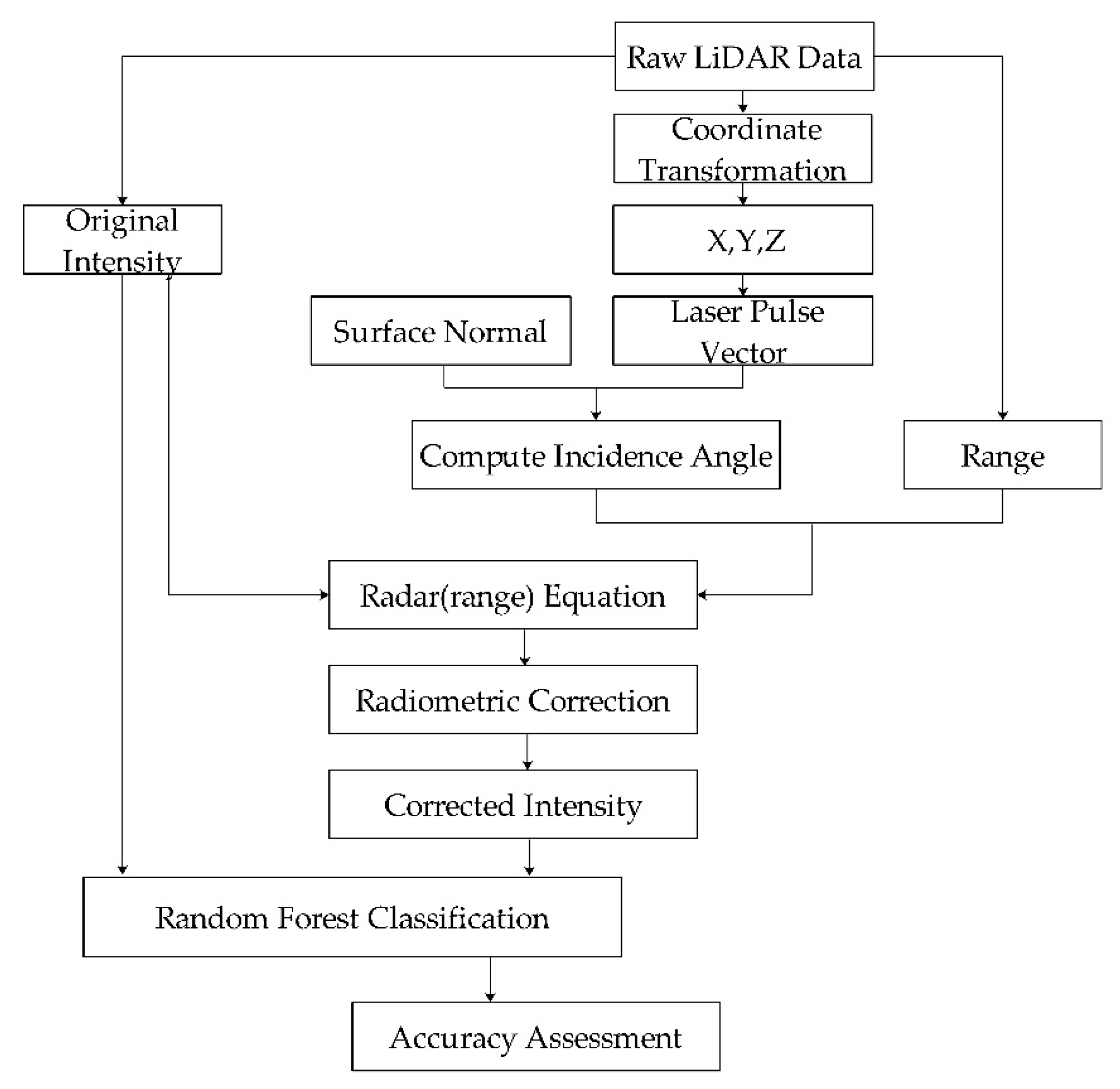
Firstly, the K-Nearest Neighbor (KNN) method is used to find the nearest N points for each point, and then the height differences between the current point and the neighboring points are calculated. A threshold value of 0.4 m is set to remove the neighboring points higher than the threshold value, and the set of points meeting the threshold condition is used as the initial set of points. The setting of the elevation threshold is mainly to reduce the calculation error of the surface normal of the building edge points and the ground points nearby. If the number of points in the initial set of points is less than 3, the surface normal of the point is (0, 0, 0). Then the initial set of points is fitted to a plane, and the normal vector of the plane at this point is calculated by the covariance matrix, singular value decomposition, and the eigenvector corresponding to the minimum singular value. The outliers for the cosine of the incident angle of the laser points are post-processed and replaced with the average of the neighboring points. Figure 2 shows the workflow of the radiometric correction of the intensity data for assessment of land cover classification.

2.4. Experiment

2.4.1. RIEGL Laser Scanning Equipment

In this study, we correct the intensity of RIEGL laser scanning equipment. RIEGL provides two types of intensity data: calibrated amplitude and relative reflectance. The calibrated amplitude is given relative to the amplitude of an echo signal at the detection threshold of the instrument. The value of the amplitude reading is a ratio, given in the units of decibel (dB). The formula of the amplitude:
A d B = 10 lg ( P e c h o P D L )
where A d B is the amplitude in decibel, P e c h o is the optical input power, P D L is the minimum detectable input power. The amplitude of the echo signal reaching the laser scanner depends on a number of parameters, including system parameters like the emitted laser pulse peak power and the receiver aperture, but also including target parameters like the target’s reflectance and range. A d B suffers from scan range dependence, so the relative reflectance as an additional attribute is provided by RIEGL. The relative reflectance is a ratio of the actual amplitude of that target to the amplitude of a white flat target at the same range, orientated orthonormal to the beam axis, and with a size in excess of the laser footprint. The value of the reflectance is also a ratio, given in the units of decibel:
ρ r e l = 10 lg ( A d B A d B , R e f ( R ) )
where ρ r e l is relative reflectance in dB, A d B is the calibrated amplitude,   A d B , R e f ( R ) is amplitude of a reference target at range R. The reflectance is nearly independent from the scan range [45].
According to Equations (11) and (12), the amplitude and reflectance of RIEGL laser scanning equipment are in dB units, which are converted as follows:
I a m p = 10 ( A d B 10 )
where A d B is the calibrated amplitude, I a m p is the converted amplitude of target.
I r e f = 10 ( ρ r e l 10 )
where ρ r e l is the relative reflectance, I r e f is the converted reflectance of target.
Finally, we correct the intensity of first type (the calibrated amplitude) by eliminating the effects of incident angle and range. The equation is:
I C a m p = I a m p R 2 R s 2 1 cos θ
where I C a m p is the intensity of first type after correction, R is the range between the sensor and the target, R s is the reference distance, cos θ is the cosine of incident angle (direction of reflection). The range is calculated by laser original coordinates ( X l a s e r ,   Y l a s e r ,   Z l a s e r ), which are decoded by the RIEGL RXP file.
The intensity of second type (the relative reflectance) is corrected by eliminating the effects of laser incident angle. The equation is:
I C r e f = I r e f 1 cos θ
where I C r e f is the intensity of second type after correction, and cos θ is the cosine of incident angle (direction of reflection).

2.4.2. Study Area and Dataset

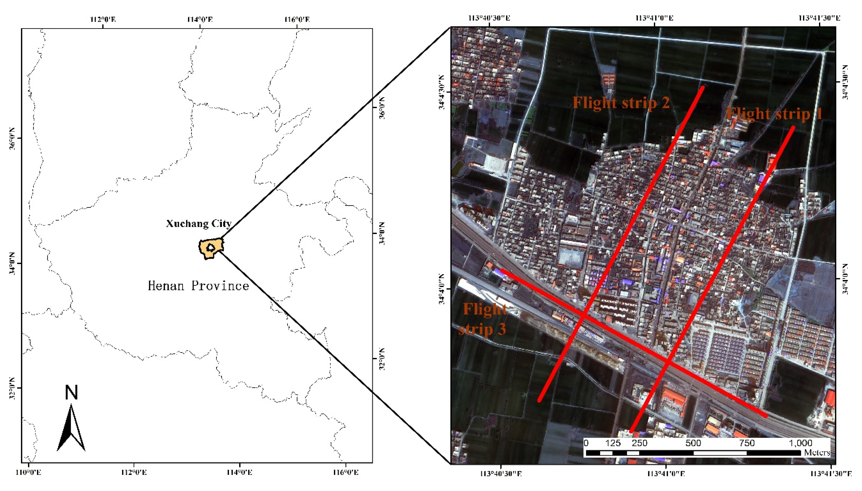
The study area is located in Xuchang City, Henan Province, China. The flight experiment was carried out on 16 March 2016. LiDAR raw data were acquired by RIEGL laser scanner system mounted on a manned aerial platform. Three strips of experimental area were shown in Figure 3. Flight strip 1 was scanned from south to north, flight strip 2 was scanned from north to south, and flight strip 3 was scanned from east to west. Three strips formed overlap shown as red lines. The RIEGL laser scanner system recorded the intensity of a single pulse. The altitude of manned aerial platform is below 300 m. Atmospheric attenuation parameter of laser transmission is negligible in this experiment. The average point cloud density of the whole survey area is 8 pts/m2. The horizontal resolution of point cloud is 0.38 m and the vertical resolution is 0.40 m. The maximum height difference between the point clouds in the study area is 72.90 m. The study area includes natural landscapes and artificial structures, including vegetation, buildings, roads, and farmlands.
Through coordinate transformation, LiDAR raw data ( X l a s e r , Y l a s e r , Z l a s e r , A d B and ρ r e l ) decoded by RXP file data were fused into discrete LiDAR point cloud data of ( X , Y , Z , I a m p ) and ( X , Y , Z , I r e f ) in the coordinate system of WGS-84 UTM Zone 49N. We corrected the intensity of the two types by Equations (15) and (16), and obtained the corrected LiDAR point clouds ( X , Y , Z , I C a m p ) and ( X , Y , Z , I C r e f ) . The LiDAR intensity data of two types before correction and after correction were converted into intensity raster images with 0.5 m resolution.

2.4.3. Evaluation Method of Intensity Correction

We used statistical analysis of samples to assess the intensity values in homogeneous areas before and after correction. Samples from homogeneous road surfaces in flight strips 1 and 2 were collected. The sample data of different scan ranges and scan angles from nadir to edges cover the entire sample area. Since the roads are flat, the incidence angle is nearly equal to the scan angle. A total of 30 samples from small rectangular areas with different scan ranges and scan angles were selected from the road surfaces. Each small rectangular area included 25–40 points. The standard deviation of the scan ranges for these points is less than 0.4 m, and the standard deviation of the scan angles for these points is less than 3°, similar to the study by Oh [46]. Figure 4 and Figure 5 show the sampling areas in flight strips 1 and 2, respectively, where the red boxes represent the rectangular sample areas and the blue line represents the flight path.
Because of some artificial errors in the sampling process of natural objects, it is not possible that all sampling points have unique intensity values on uniform surfaces. Meanwhile, LiDAR intensity values of the two types have been stretched after correction, leading to different dimensions, so we used the median and the coefficient of variation (CV) to assess the correction effects. The formula of the coefficient of variation is:
C V = σ μ
where CV denotes the dispersion degree of the sample data, σ is the standard deviation of the sample value, and μ is the mean of the sample values.
We assessed the classification accuracies for land cover types based on uncorrected and corrected intensity data of two types by using the random forest method. Six classes were differentiated: building, pavement/road, tree, cropland, grass, and bare soil. Building, pavement/road, and tree are predominant land-cover types, while cropland, grass, and bare soil are minor classes in the scenes of the study area (see Figure 3). Google map image data with a resolution of 0.25 m was used as a reference to randomly select samples of six classes (see Table 1). Table 1 shows total number of samples for six land cover types and independent-sample Kruskal–Wallis test for differences. Moreover, 70% of samples were used as training data and 30% of samples were used for verification. There is no overlap between the training samples and the verification samples. Overall accuracy were used to evaluate the classification accuracy of the whole data set. Producer’s accuracy (PA) and user’s accuracy (UA) were used to assess the classification accuracy of each class. We added overall class accuracy (CA) for a single class defined by Singh et al. [12], which takes into account the misclassification error and omission error of each class.

3. Results

3.1. Assessment of Homogeneous Areas

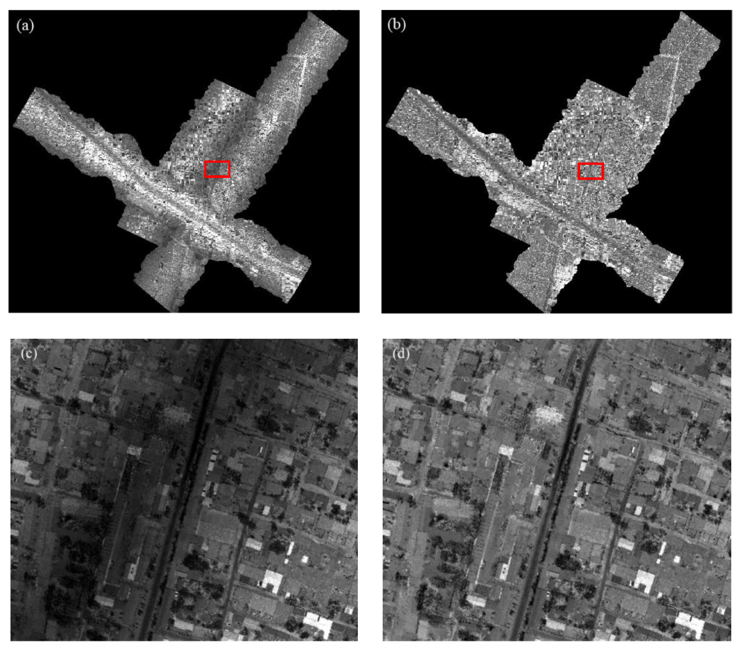
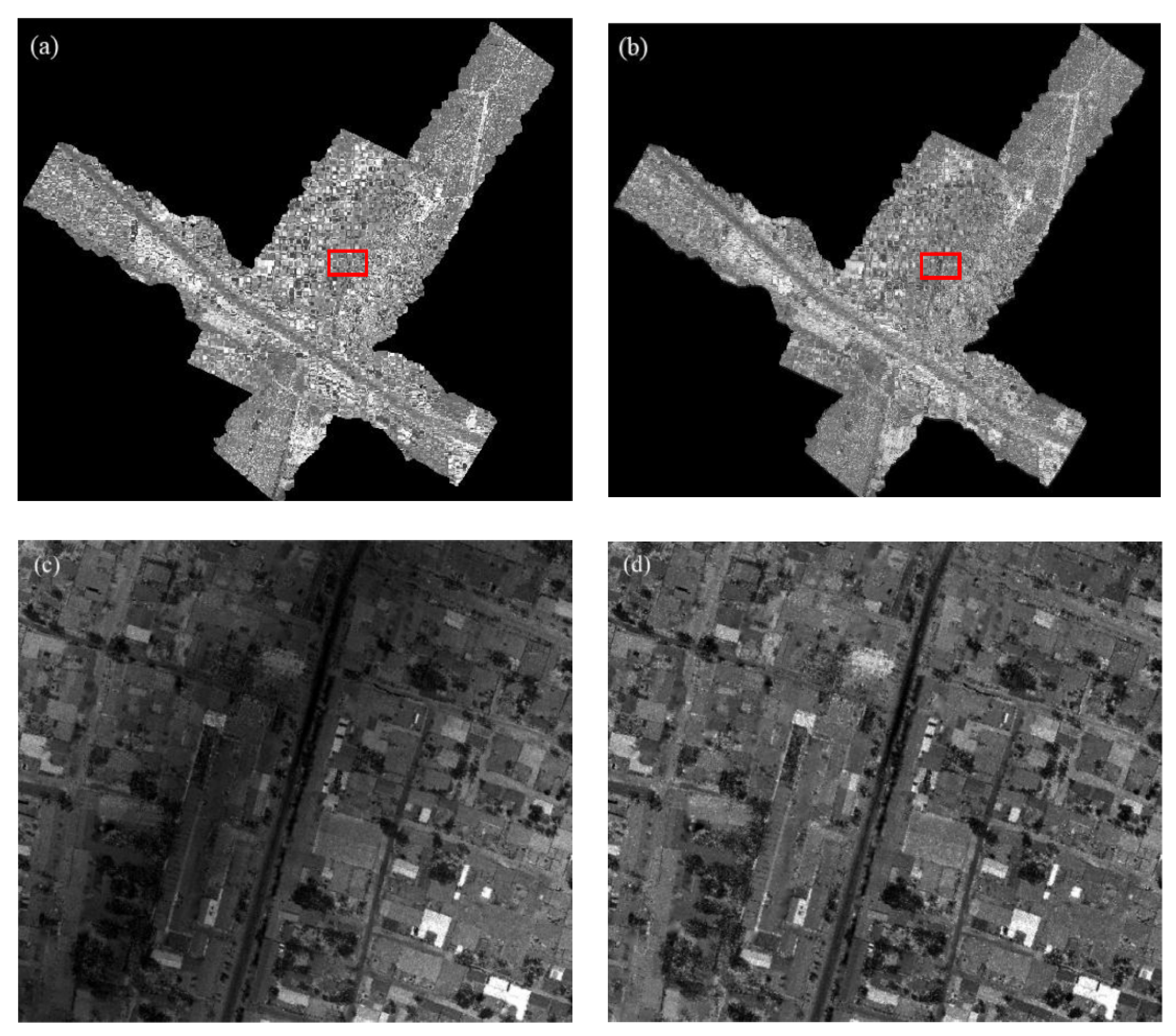
LiDAR intensity data of the two types before and after correction are shown in Figure 6 and Figure 7. Visual analyses suggest that the intensity values at the nadir are significantly higher than those at the edges before correction, which also proved that intensity correction is meaningful. This can be explained by the increase in the range at the edges, and the decrease of received laser energy. Figure 6a shows that the intensity values of the overlapping regions of strips 1, 2, and 3 were not consistent. Theoretically, when scanning the same target, the intensity values of the same target were close to each other in different flight strips. In the paper, in order to highlight the intensity correction effects of proposed incident angle, we only collected the samples from roads, not other classes. Different scan ranges and incident angles from nadir to edges cover the entire sample area in flight strips 1 and 2.
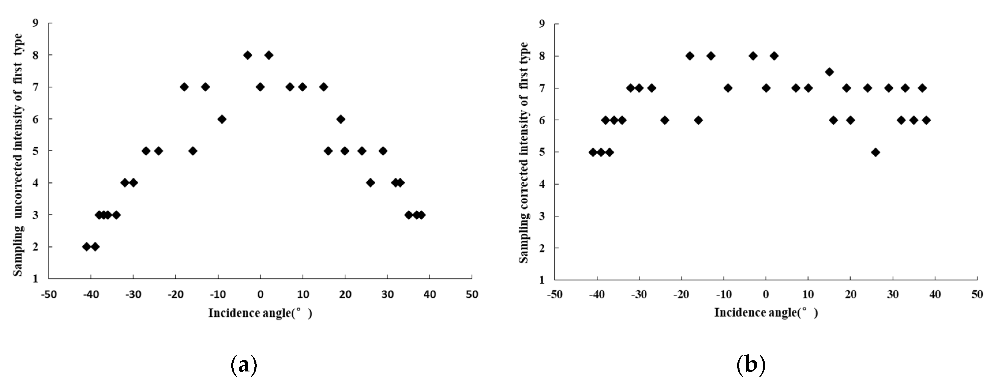
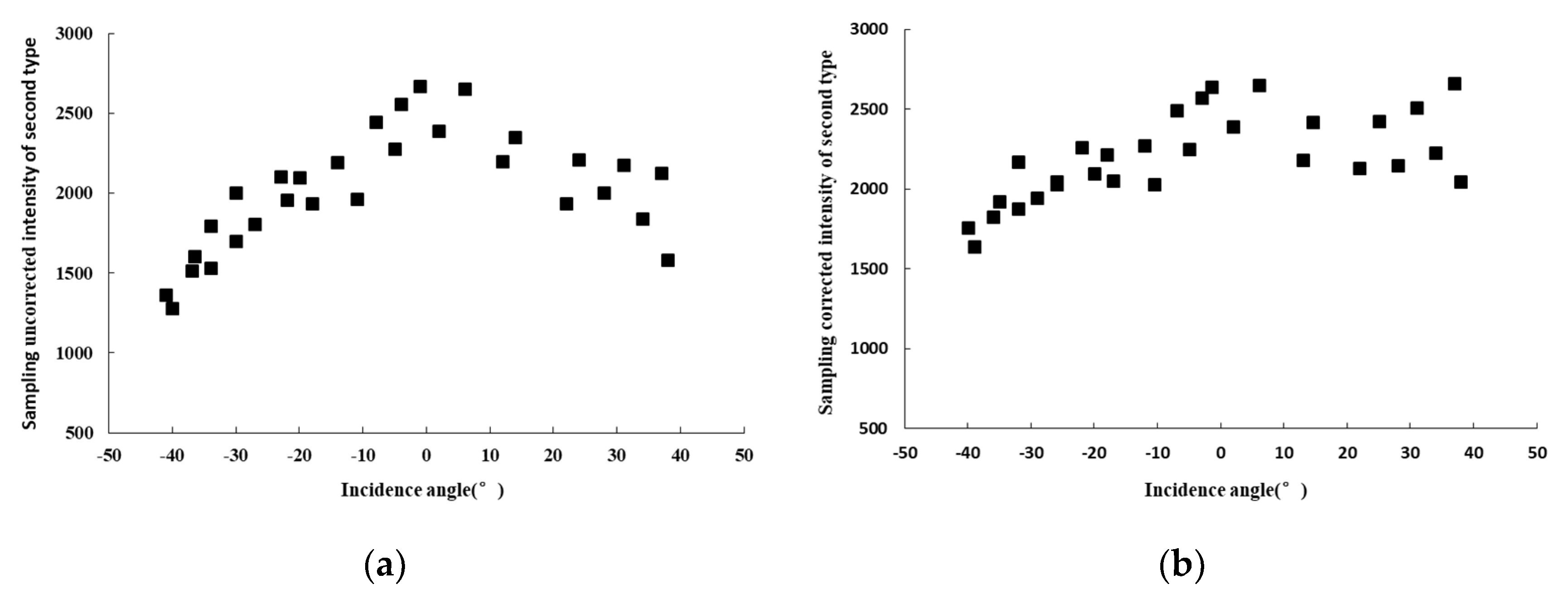
In order to further evaluate the results of intensity correction, we compared the intensity statistics of the road before and after correction. In flight strip 1, the median values of the intensity of the first type for each sample were shown in Figure 8a,b. The intensity values before correction I a m p were between 2 and 8 while the intensity values after correction I C a m p were from 5 to 8, which indicated that the intensity values of the first type after correction I C a m p were more concentrated. The median values of intensity of the second type for each sample were shown in Figure 9a,b. The intensity values of the second type before correction I r e f were between 1200 and 2600, while the intensity values after correction I C r e f were between 1500 and 2600. The results show that the intensity values of the second type after correction I C r e f were more concentrated, so were the corrected intensity values of the first type I C a m p . Based on the results in Table 2, the CV of the intensity of the first type before correction I a m p was 0.36, the CV of the intensity of the first type after correction I C a m p was 0.14, and the ratio of variation coefficient after correction to that before correction was 0.39 (less than 1), indicating that the theoretical model using the proposed correction method was effective. The CV of the intensity of the second type before correction I r e f was 0.20; the CV of the intensity of the second type after correction I C r e f was 0.14, the ratio of variation coefficient after correction to that before correction was 0.7, which also showed that the theoretical correction using the proposed incidence angle was effective. Moreover, it was found that the CV of the intensity values of the second type I r e f was less than that of the first type I a m p , the relative reflectance before correction is more useful than the calibrated amplitude provided by the RIEGL system.
In flight strip 2, the intensity of the first type before correction I a m p and after correction I C a m p were 2 to 8 and 5 to 8, respectively. The intensity of the second type before correction I r e f and after correction I C r e f were 1200 to 2600 and 1600 to 2600, respectively (see Figure 10 and Figure 11). The results show that the intensity values of the two types ( I C a m p and I C r e f ) were more concentrated after correction, which was in line with the conclusions obtained in flight strip 1, indicating that the correction was effective. We further compared the CV of the intensity before and after correction in Table 3, the CV of the intensity of the first type before correction I a m p and after correction I C a m p was 0.30 and 0.13, the ratio of variation coefficient after correction to that before correction was 0.43. The CV of the intensity of the second type before correction I r e f and after correction I C r e f was 0.18 and 0.12, the ratio of variation coefficient after correction to that before correction was 0.67 (less than 1). These results are also in line with the results from flight strip 1, the smaller the CV and ratio of coefficient variation, the better the correction results, which indicated that the improved theoretical correction by using proposed incidence angle is effective.
According to the median intensity values of the sample data before and after correction in flight strip 1 and 2 in Figure 8, Figure 9, Figure 10 and Figure 11, the intensity variation of the first type before correction I a m p was larger than the intensity variation of the second type I r e f , which partly explains the range correction for the intensity of the first type I a m p is necessary in addition to incidence angle correction. The intensity of the first type after range and incidence angle correction is a value directly proportional to the spectral reflectance. Although the intensity of the second type has been calibrated by the RIEGL manufacturer, it is still necessary to eliminate the influence of incident angle, obtaining the intensity value proportional to the spectral reflectance.

3.2. Comparison of Land Cover Classification Performance Based on Airborne LiDAR Intensity before and after Correction

Using the random forest method, which is one of the best classification methods in machine learning [47], the classification accuracies for land cover based on the uncorrected and corrected intensity data of two types were compared. The four scenarios include the intensity of the first type (calibrated amplitude) before correction I n t e n s i t y a m p , the intensity of the first type (calibrated amplitude) after correction I n t e n s i t y C a m p , the intensity of the second type (reflectance) before correction I n t e n s i t y r e f , and the intensity of the second type (reflectance) after correction I n t e n s i t y C r e f .
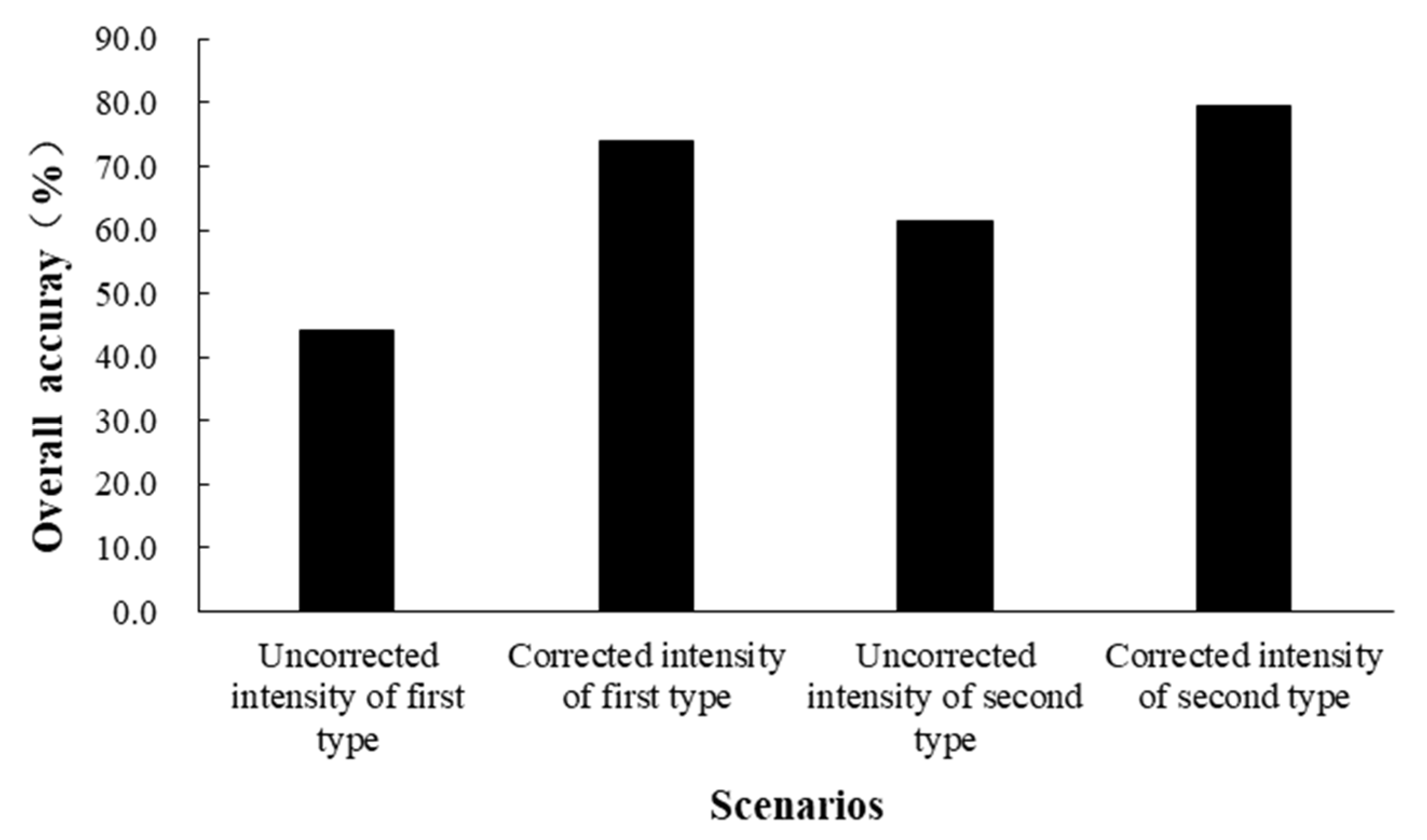
From overall classification accuracies shown in Figure 12, the overall accuracy based on the intensity of the first type before correction I n t e n s i t y a m p and after correction I n t e n s i t y C a m p was 44.10% and 74.11%, respectively. The overall accuracy based on the intensity of the second type before correction I n t e n s i t y r e f and after correction I n t e n s i t y C r e f was 61.38% and 79.59%. After correction by the improved theoretical model, the overall classification accuracy based on the intensity of first type ( I n t e n s i t y C a m p ) was significantly improved by 30.01%, the overall classification accuracy based on the intensity of second type ( I n t e n s i t y C r e f ) increased by 18.21%. The overall classification accuracy based on the intensity of two types after correction was higher than that obtained before correction. The overall classification accuracy based on the uncorrected intensity of the first type I n t e n s i t y a m p was less than that the uncorrected intensity of the second type I n t e n s i t y r e f . For both uncorrected and corrected intensity data, the intensity of the second type ( I n t e n s i t y r e f and   I n t e n s i t y C r e f ) was more valuable than the intensity of first type ( I n t e n s i t y a m p   and   I n t e n s i t y C a m p ) for land cover classification.
Table 4 shows the comparison of classification accuracies for the six land-cover types based on airborne LiDAR intensity before and after correction. The corrected airborne LiDAR intensity data has good performance in identifying tree types, with the highest CA (78.14% and 80.19%) among all ground objects. The second highest classification accuracy was buildings with a CA of 61.97% and 68.70%, followed by roads with a CV of 48.33% and 58.98%, respectively. Bare soil, grass, and cropland classes have the worst classification accuracy. The reason is that when the laser pulses hit grasses and croplands, the returned signal may come from bare soil. Although not all land cover types can be well classified, the proposed intensity correction method can enhance the separability of the land cover features.
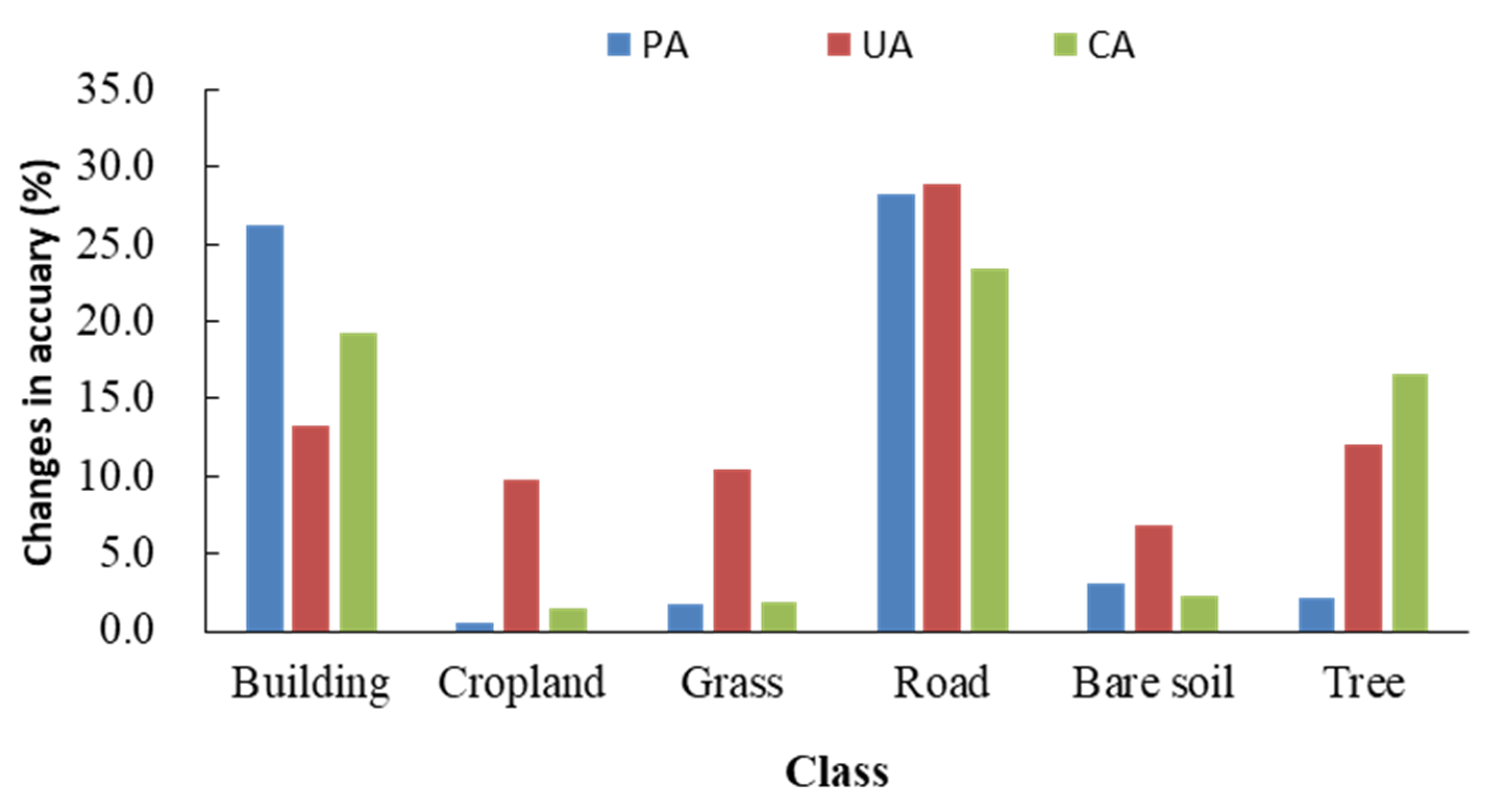
By analyzing the classification accuracies of the uncorrected intensity of second types I n t e n s i t y r e f and the first I n t e n s i t y a m p presented in Figure 13, the classification accuracy of all classes showed a net increase. The highest accuracy improvements (28.21% and 28.94%) in PA and UA were achieved for the roads. Net increases of buildings in PA and UA were 26.21% and 13.20%, whereas the net increase in PA of cropland, grass, bare soil, and tree types was all less than 5% (0.51%, 1.69%, 3.13%, and 2.08%, respectively). The net increase in UA of cropland, grass, bare soil, and tree types were larger than 5% (9.77%, 10.46%, 6.84%, and 12.00%, respectively). Single class of all types with CV showed a net increase, as well as the PA and UA. The road achieved the highest CA of the net increases with 23.43%, followed by building (19.27%), the net increase of tree was 16.54%, the net growth of bare soil, cropland, grass type were significantly lower than the above types, bare soil types was 2.32%, the grass type was 1.89%, the cropland type was 1.50%. One should note that using the intensity of the second type I n t e n s i t y r e f was more beneficial than the intensity of the first type for land-cover classification, especially distinguish road, building, and tree classes. It demonstrated that the I n t e n s i t y r e f data calibrated by RIEGL had a positive impact on the accuracy of land cover classification.
Figure 14 illustrated net changes in the classification accuracies of single class based on the corrected intensity of the first type I n t e n s i t y C a m p vs. the uncorrected intensity of the first type I n t e n s i t y a m p . Net increases in PA and UA were observed for all classes. The classification accuracy for bare soil and grass improved more 40%, the bare soil and grass were barely identified based on the uncorrected intensity of the first type. The net increase in PA and UA of cropland and road was more than 30%. The building and tree showed minor changes in PA and UA, they produced more than 60% in PA. All classes resulted in net gains in CA, especially the bare soil produced the highest net gains (50.39%). The classification accuracy of the intensity after correction I n t e n s i t y C a m p was significantly improved compared with the uncorrected intensity of the first type I n t e n s i t y a m p , especially in distinguishing the bare soil and grass. The correction can help improve the classification of some land cover features. Before correction, it was explained that overlap between intensity values of grass and soil and intensity values of soil and cropland. After correction, the intensity values of these land cover features showed some degree of separability.
Figure 15 showed the net changes in the classification accuracies of single class based on the corrected intensity of the second type I n t e n s i t y C r e f vs. the uncorrected intensity of the second type I n t e n s i t y r e f . While PA decreased 2.59% for building, there are net increases in PA and UA for all classes. Bare soil and grass showed the highest net increase (73.44% and 60.16%, 61.91% and 57.45%) in PA and UA. The classification results of bare soil and grass were poor based on the intensity of the second type before correction I n t e n s i t y r e f , which was in line with the conclusion based on the intensity of the first type before correction I n t e n s i t y a m p . All classes resulted in net gains in CA, especially the bare soil and grass produced the highest net gains (54.38% and 49.54%), this is in line with the results from the intensity of first type after correction I n t e n s i t y C a m p vs. before correction I n t e n s i t y a m p . It also indicates that the identification of bare soil and grass can be effectively improved based on the corrected intensity. The net increase in the classification accuracy of cropland was 47.15%, and the corrected intensity was significant in the identification of cropland. The net increase in the classification accuracy of buildings and tree classes was the lowest but greater than 10%. The separability amongst the intensity values of grass, cropland, and soil were significantly increased after correction.
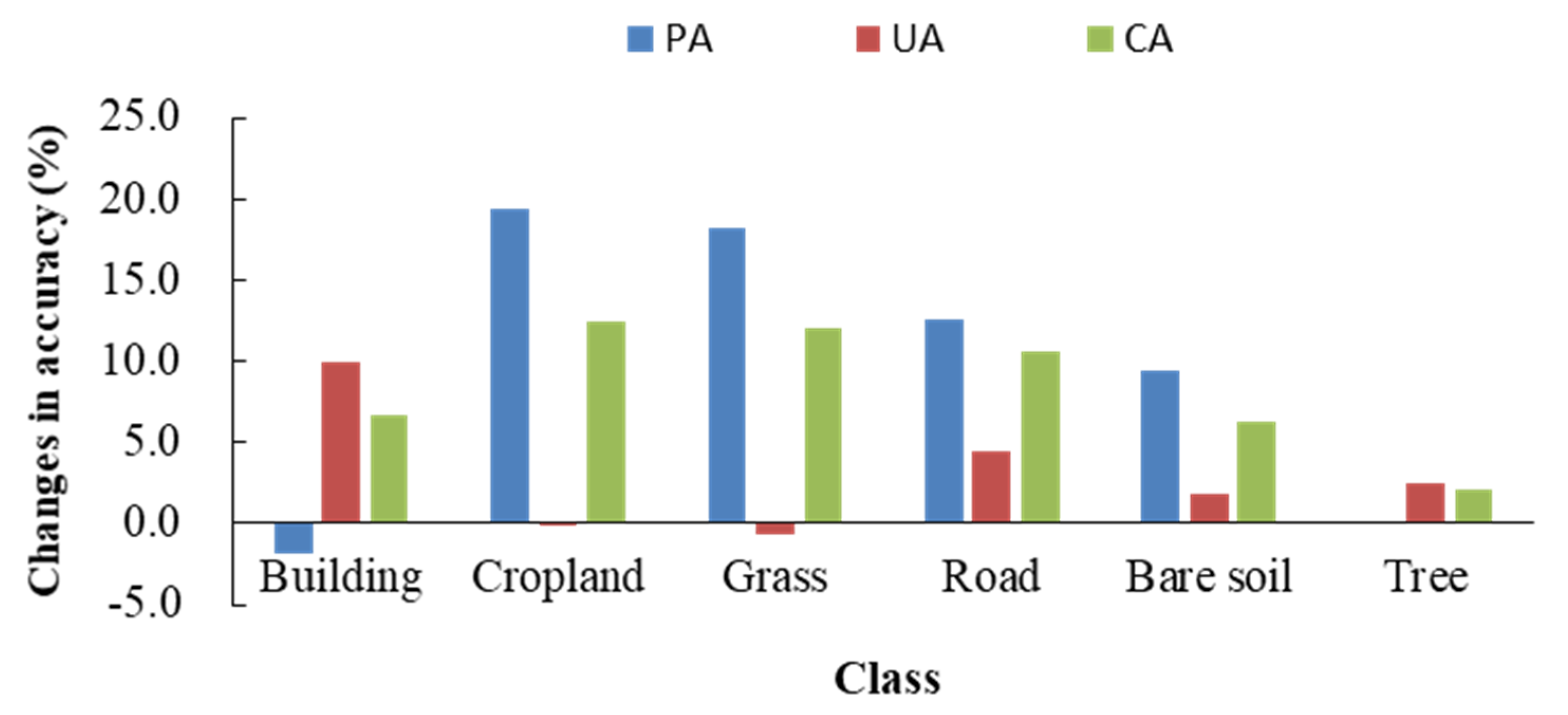
Figure 16 shows net changes in the classification accuracies of single class based on the corrected intensity of the second type I n t e n s i t y C r e f vs. the corrected intensity of the first type I n t e n s i t y C a m p . While Cropland and grass show a net decrease of 0.18% and 0.72% in UA, the net increase in PA were the highest (19.37% and 18.20%), improvement in CA were 12.44% and 12.07%. Road produced net gains in PA(12.50%), 4.42% for UA, 10.65% for CA. Building shows a net increases in UA(9.92%) and CA(6.72%), while building slightly decreased 1.8% in PA. Improvement in PA for bare soil is 9.38%, 1.82% for UA, 6.31% for CA. The PA, UA, and CA of tree also showed a net increase, but only increased by 0.04%, 2.50%, and 2.05%. When identifying tree types, their PA and UA were both greater than 85%, so the intensity of two types after correction in identifying tree types was basically equivalent. A significant improvement in separability between the intensity values of tree and other classes was shown after correction. This can be explained by the fact that vegetation has a strong reflective peak in the near-infrared band. The separability of trees were higher than other vegetation, e.g., grasses and croplands. The reason is that when the laser pulses hit grasses and croplands, the returned signal may partly come from bare soil. In general, the intensity of the second type is more useful than the intensity of first type for land cover classification.

4. Discussion

As can be seen from the above results, the intensity of the two types before and after correction were compared and assessed. The corrected intensity data have been proven to be effective by sample statistical analysis and classification accuracy assessment. The CV and ratio of coefficient variation of the two corrected intensity are smaller. This finding is consistent with Höfle and Pfeifer [25], where the variation coefficient of the intensity value by using the theoretical model in the homogeneous region is lower than that before correction. As shown in Figure 7, Figure 8, Figure 9 and Figure 10, when the incident angle is greater than 15 degrees, the influence of the incident angle on the intensity value is significantly enhanced. Kukko et al. [48] found that the effect of incident angle on the intensity was obvious, which is the consistent with this study.
To evaluate the performance of the proposed method, the method is compared with the method proposed by Yan and Shaker [13]. In the method proposed by Yan and Shaker [13], a surface slope threshold was used to determine whether the scan angle or the incident angle should be used for intensity correction. When the slope was less than or equivalent to 40°, the incidence angle was used in the radar (range) equation; when the slope exceeded 40°, the scan angle was used instead. Table 5 shown comparisons of classification accuracies for six land cover types obtained from the proposed method (Proposed correction I and Proposed correction II) and the method of Yan and Shaker [13] (Method I and Method II) during the same region. The incident angle is referenced and calculated by Yan and Shaker [13] in Method I and II. Then, in Method I, we corrected the intensity of first form (the calibrated amplitude) by the Equation (15). It eliminated the effects of incident angle and range. In Method II, we corrected the intensity data of the second form (the relative reflectance) by the Equation (16). It only eliminated the effects of incident angle. The classification accuracy of the results obtained by the proposed method were almost the highest. The results suggest that the proposed method had better performance than the method of Yan and Shaker [13] in this area. The recognition of building and tree were superior to other types in all methods. The reason is that when the laser pulses hit low vegetation (grass and cropland), the returned signal may come from bare soil. The proposed intensity correction method in identifying building and tree achieved better results than Method I and II. Cropland, grass, and soil were the worst of classification accuracy in Method I and II, which were almost unrecognized. These may be explained by considering that the accuracy of the incidence angle derived on from the TIN model is not guaranteed and limited. Moreover, slope threshold setting is highly dependent on the terrain and cover of the study area, which may affect the correction results and the separability of the land cover features.
The intensity values after correction were also more useful than the intensity before correction for land cover classification. Although the intensity of reflectance has been calibrated by the RIEGL manufacturer, our study suggests that it is still necessary to eliminate the influence of incident angle using intensity for identification and classification. The overall classification accuracy of the corrected intensity of reflectance was improved by 18.21%. Calders et al. [39] evaluated the intensity of RIEGL VZ-400, and concluded that the reflectance data provided by RIEGL VZ-400 has certain errors in users’ analysis that need radiation correction. The classification accuracy based on corrected intensity has been improved in identifying six land-cover types, especially tree types, with the highest CA (78.14% and 80.19%) among all ground objects. This is different from the conclusions of the study by Yan and Shaker [13] in which intensity correction was not applicable for tree canopies.
However, the corrected intensity values are only proportional to the ground reflectance and do not reflect the true reflectance values. The radar (range) equation was simplified under the assumption that the target was an extended Lambertian. The effect of incidence angle was corrected by using Lambert’s cosines law. In future research, we will consider a realistic illumination model by taking into account the superposition of specular reflected light, diffuse reflected light and ambient light to eliminate the incident effect and improve the actual precision of intensity values. We will perform rigorous radiometric correction and calibration to extract the reflectance values, using the brightness measurement.
From the transmitted signal to the received signal, the system, environment, and target effects may lead to errors of intensity values. In addition to the influence of the incidence angle and scanning range, other parameters such as transmission power and AGC and transmission errors of the system may affect the intensity. However, we assumed that instrument parameters were stable, without considering the influence of the instrument system parameters, therefore instrument effects need to be further analyzed. Because the aircraft flew at a low altitude of 300 m, we assumed that the effect of atmosphere attenuation on LiDAR intensity can be ignored, but, in fact, the laser energy in the process of transmission is affected by temperature, humidity, and air pressure. The atmospheric attenuation need to be corrected in future research.

5. Conclusions

We presented a theoretical correction using the proposed incidence angle to solve the problem of inconsistent in the overlapping region of airborne LiDAR intensity data. The corrected intensity is directly proportional to the ground reflectance for land cover classification. The intensity of two types (amplitude and reflectance information) from the RIEGL scanner were corrected, and the effectiveness of the improved method was evaluated by the sample statistical method and classification accuracy assessment. Compared with the intensity values before correction, the intensity values after correction are more concentrated and the coefficient of variation is smaller, which proves that the method is effective. It is found that when the incident angle is greater than 15 degrees, the influence of the incident angle on the intensity value is significantly enhanced. It also indicates that the effect of incidence angle cannot be ignored in the intensity correction of airborne LiDAR.
The classification accuracies for land cover based on the uncorrected and corrected intensity data of two types were compared. Six classes are differentiated: building, pavement/road, tree, cropland, grass, and bare soil. In the case of uncorrected data, the intensity of the second type (reflectance) is more valuable than the intensity of first type (amplitude) for land cover classification, especially for distinguishing road, building, and tree classes. After correction the overall accuracy of the intensity of the first type (amplitude) is significantly improved by 30.01%, the overall accuracy of the intensity of second form (reflectance) is increased by 18.21%. The classification results of bare soil and grass were poor based on the intensity of the two type before correction. Distinguishing bare soil and grass after correction show large improvements. Moreover, the corrected intensity data has good performance in identifying trees. In the case of correction, the intensity of the second type (reflectance) is more useful than the intensity of first type (amplitude) for land cover classification. We recommend that radiometric correction of airborne LiDAR intensity data be conducted to improve classification accuracy. This correction approach not only avoids manual intervention, but also has theoretical bases. The study is significant for improving the application of multispectral and hyper-spectral LiDAR intensity data.

Author Contributions

Conceptualization, Q.W. and P.D.; methodology, Q.W. and R.Z.; software, Y.M.; validation, Q.W., and Y.M.; formal analysis, Y.J.; investigation, R.Z.; resources, Q.W.; data curation, Y.M.; writing—original draft preparation, Q.W.; writing—review and editing, Q.W.; P.D. and Y.J.; visualization, Q.W.; supervision, P.D.; project administration, R.Z.; funding acquisition, R.Z. and Y.J. All authors have read and agreed to the published version of the manuscript.

Funding

This research was funded by the National Natural Science Foundation of China, grant number 41371434, and Fundamental Research Funds for Central Non-Profit Scientific Institution, grant number 1610132020030.

Institutional Review Board Statement

Not applicable.

Informed Consent Statement

Not applicable.

Data Availability Statement

The data presented in this study are available on request from the corresponding author. The data are not publicly available due to collecting data by the team and the partner, the partner demanded strictly not sharing data.

Acknowledgments

The authors deeply thank Zhenxin Sun for providing the LiDAR raw data sets and constructive discussions. We are also grateful to Haili Sun and Yanan Yan for their suggestions.

Conflicts of Interest

The authors declare no conflict of interest. The funders had no role in the design of the study; in the collection, analyses, or interpretation of data; in the writing of the manuscript, or in the decision to publish the results.

References

  1. Kashani, A.G.; Olsen, M.J.; Parrishet, C.E. A Review of LIDAR Radiometric Processing: From Ad Hoc Intensity Correction to Rigorous Radiometric Calibration. Sensors 2015, 15, 28099–28128. [Google Scholar] [CrossRef] [PubMed] [Green Version]
  2. Eitel, J.U.H.; Höfle, B.; Vierling, L.A.; Abellán, A.; Asner, G.P.; Deems, J.S.; Glennie, C.L.; Joerg, P.C.; LeWinter, A.L.; Magney, T.S.; et al. Beyond 3-D: The new spectrum of lidar applications for earth and ecological sciences. Remote Sens. Environ. 2016, 186, 372–392. [Google Scholar] [CrossRef] [Green Version]
  3. Huang, J.X.; Sedano, F.; Huang, Y.B.; Ma, H.Y.; Li, X.L.; Liang, S.L.; Tian, L.Y.; Zhang, X.D.; Fan, J.L.; Wu, W.B. Assimilating a synthetic Kalman filter leaf area index series into the WOFOST model to estimate regional winter wheat yield. Agric. For. Meteorol. 2016, 216, 188–202. [Google Scholar] [CrossRef]
  4. Ramezan, C.A.; Warner, T.A.; Maxwell, A.E. Evaluation of sampling and cross-validation tuning strategies for regional-scale machine learning classification. Remote Sens. 2019, 11, 185. [Google Scholar] [CrossRef] [Green Version]
  5. Marchi, N.; Pirotti, F.; Lingua, E. Airborne and terrestrial laser scanning data for the assessment of standing and lying deadwood: Current situation and new perspectives. Remote Sens. 2018, 10, 1356. [Google Scholar] [CrossRef] [Green Version]
  6. Baltsavias, E.P. A comparison between photogrammetry and laser scanning. ISPRS J. Photogramm. Remote Sens. 1999, 54, 83–94. [Google Scholar] [CrossRef]
  7. Song, J.H.; Han, S.H.; Yu, K.Y.; Kim, Y.I. Assessing the possibility of land-cover classification using LIDAR intensity data. Int. Arch. Photogramm. Remote Sens. Spatial Inf. Sci. 2002, 34, 259–262. [Google Scholar]
  8. Coren, F.; Sterzai, P. Radiometric correction in laser scanning. Int. J. Remote Sens. 2006, 27, 3097–3104. [Google Scholar] [CrossRef]
  9. Donoghue, D.N.; Watt, P.J.; Cox, N.J.; Wilson, J. Remote sensing of species mixtures in conifer plantations using LIDAR height and intensity data. Remote Sens. Environ. 2007, 110, 509–522. [Google Scholar] [CrossRef]
  10. Chust, G.; Galparsoro, I.; Borja, A. Coastal and estuarine habitat mapping, using LIDAR height and intensity and multi-spectral imagery. Estuar. Coast. Shelf Sci. 2008, 78, 633–643. [Google Scholar] [CrossRef]
  11. Gatziolis, D. Dynamic range-based intensity normalization for airborne, discrete return LiDAR data of forest canopies. Photogramm. Eng. Remote Sens. 2011, 77, 251–259. [Google Scholar] [CrossRef]
  12. Singh, K.K.; Vogler, J.B.; Shoemaker, D.A.; Meentemeyer, R.K. LiDAR-Landsat data fusion for large-area assessment of urban land cover: Balancing spatial resolution, data volume and mapping accuracy. ISPRS J. Photogramm. Remote Sens. 2012, 74, 110–121. [Google Scholar] [CrossRef]
  13. Yan, W.Y.; Shaker, A. Radiometric Correction and Normalization of Airborne LIDAR Intensity Data for Improving Land-Cover Classification. IEEE Trans. Geosci. Remote Sens. 2014, 52, 7658–7673. [Google Scholar]
  14. Zhu, X.; Wang, T.; Darvishzadeh, R.; Skidmore, A.K.; Niemann, K.O. 3D leaf water content mapping using terrestrial laser scanner backscatter intensity with radiometric correction. ISPRS J. Photogramm. Remote Sens. 2015, 110, 14–23. [Google Scholar] [CrossRef]
  15. You, H.; Wang, T.; Skidmore, A.; Xing, Y. Quantifying the Effects of Normalisation of Airborne LiDAR Intensity on Coniferous Forest Leaf Area Index Estimations. Remote Sens. 2017, 9, 163. [Google Scholar] [CrossRef] [Green Version]
  16. Goodale, R.; Hopkinson, C.; Colville, D.; Amirault-Langlais, D. Mapping piping plover (Charadrius melodus melodus) habitat in coastal areas using airborne lidar data. Can. J. Remote Sens. 2007, 33, 519–533. [Google Scholar] [CrossRef]
  17. Im, J.; Jensen, J.R.; Hodgson, M.E. Object-based land cover classification using high-posting-density LIDAR data. GISci. Remote Sens. 2008, 45, 209–228. [Google Scholar] [CrossRef] [Green Version]
  18. Antonarakis, A.; Richards, K.; Brasington, J. Object-based land cover classification using airborne LiDAR. Remote Sens. Environ. 2008, 112, 2988–2998. [Google Scholar] [CrossRef]
  19. Buján, S.; González-Ferreiro, E.; Reyes-Bueno, F.; Barreiro-Fernández, L.; Crecente, R.; Miranda, D. Land use classification from LiDAR data and ortho-images in arural area. Photogramm. Rec. 2012, 27, 401–422. [Google Scholar] [CrossRef]
  20. Chen, Z.; Gao, B. An Object-Based Method for Urban Land Cover Classification Using Airborne Lidar Data. IEEE J. Sel. Top. Appl. Earth Observ. Remote Sens. 2014, 7, 4243–4254. [Google Scholar] [CrossRef]
  21. Yan, W.Y.; Shaker, A.; El-Ashmawy, N. Urban Land Cover Classification Using Airborne Lidar Data: A Review. Remote Sens. Environ. 2015, 158, 295–310. [Google Scholar] [CrossRef]
  22. Yan, W.Y.; Shaker, A.; Habib, A.; Kersting, A.P. Improving classification accuracy of airborne LIDAR intensity data by geometric calibration and radiometric correction. ISPRS J. Photogramm. Remote Sens. 2012, 67, 35–44. [Google Scholar] [CrossRef]
  23. Yan, W.Y.; Shaker, A. Radiometric normalization of overlapping LiDAR intensity data for reduction of striping noise. Int. J. Digit. Earth 2016, 9, 13. [Google Scholar] [CrossRef]
  24. Xia, S.B.; Chen, D.; Wang, R.S.; Li, J.; Zhang, X.C. Geometric Primitives in LiDAR Point Clouds: A Review. IEEE J. Sel. Top. Appl. Earth Observ. Remote Sens. 2020, 13, 685–707. [Google Scholar] [CrossRef]
  25. Höfle, B.; Pfeifer, N. Correction of laser scanning intensity data: Data and model-driven approaches. ISPRS J. Photogramm. Remote Sens. 2007, 62, 415–433. [Google Scholar] [CrossRef]
  26. Kaasalainen, S.; Ahokas, E.; Hyyppa, J.; Suomalainen, J. Study of Surface Brightness from Backscattered Laser Intensity: Calibration of Laser Data. IEEE Geosci. Remote Sens. Lett. 2005, 2, 255–259. [Google Scholar] [CrossRef]
  27. Kaasalainen, S.; Hyyppä, J.; Litkey, P.; Hyyppä, H.; Ahokas, E.; Kukko, A.; Kaartinen, H. Radiometric calibration of ALS intensity. Int. Arch. Photogramm. Remote Sens. Spatial Inf. Sci. 2007, 36, 201–205. [Google Scholar]
  28. Kaasalainen, S.; Kukko, A.; Lindroos, T.; Litkey, P.; Kaartinen, H.; Hyyppa, J.; Ahokas, E. Brightness Measurements and Calibration With Airborne and Terrestrial Laser Scanners. IEEE Trans. Geosci. Remote Sens. 2008, 46, 528–534. [Google Scholar] [CrossRef]
  29. Kaasalainen, S.; Hyyppä, H.; Kukko, A.; Litkey, P.; Ahokas, E.; Hyyppa, J.; Lehner, H.; Jaakkola, A.; Suomalainen, J.; Akujarvi, A.; et al. Radiometric calibration of LIDAR intensity with commercially available reference targets. IEEE Trans. Geosci. Remote Sens. 2009, 47, 588–598. [Google Scholar] [CrossRef]
  30. Kaasalainen, S.; Pyysalo, U.; Krooks, A.; Vain, A.; Kukko, A.; Hyyppä, J.; Kaasalainen, M. Absolute Radiometric Calibration of ALS Intensity Data: Effects on Accuracy and Target Classification. Sensors 2011, 11, 10586–10602. [Google Scholar] [CrossRef]
  31. Tan, K.; Cheng, X.J. Correction of Incidence Angle and Distance Effects on TLS Intensity Data Based on Reference Targets. Remote Sens. 2016, 8, 251. [Google Scholar] [CrossRef] [Green Version]
  32. Scaioni, M.; Höfle, B.; Baungarten, K.A.P.; Barazzetti, L.; Previtali, M.; Wujanz, D. Methods From Information Extraction From LiDAR Intensity Data and Multispectral LiDAR Technology. Int. Arch. Photogramm. Remote Sens. Spatial Inf. Sci. 2018, 42, 1503–1510. [Google Scholar] [CrossRef] [Green Version]
  33. Ding, Q.; Chen, W.; King, B.; Liu, Y.X.; Liu, G.X. Combination of overlap-driven adjustment and Phong model for LIDAR intensity correction. ISPRS J. Photogramm. Remote Sens. 2013, 75, 40–47. [Google Scholar] [CrossRef]
  34. Korpela, I.S. Mapping of understory lichens with airborne discrete-return LiDAR data. Remote Sens. Environ. 2008, 112, 3891–3897. [Google Scholar] [CrossRef]
  35. Vain, A.; Yu, X.; Kaasalainen, S.; Hyyppa, J. Correcting airborne laser scanning intensity data for automatic gain control effect. IEEE Geosci. Remote Sens. Lett. 2010, 7, 511–514. [Google Scholar] [CrossRef]
  36. Korpela, I.; Ørka, H.O.; Hyyppä, J.; Heikkinen, V.; Tokola, T. Range and AGC normalization in airborne discrete-return LIDAR intensity data for forest canopies. ISPRS J. Photogramm. Remote Sens. 2010, 65, 369–379. [Google Scholar] [CrossRef]
  37. Fang, W.; Huang, X.; Zhang, F.; Li, D. Intensity Correction of Terrestrial Laser Scanning Data by Estimating Laser Transmission Function. IEEE Trans. Geosci. Remote Sens. 2015, 53, 942–951. [Google Scholar] [CrossRef]
  38. Tan, K.; Cheng, X.J. Intensity data correction based on incidence angle and distance for terrestrial laser scanner. J. Appl. Remote Sens. 2015, 9, 094. [Google Scholar] [CrossRef]
  39. Calders, K.; Disney, M.I.; Armst, J.; Burt, A.; Brede, B.; Origo, N.; Muir, J.; Nightingale, J. Evaluation of the Range Accuracy and the Radiometric Calibration of Multiple Terrestrial Laser Scanning Instruments for Data Interoperability. IEEE Trans. Geosci. Remote Sens. 2017, 55, 2716–2724. [Google Scholar] [CrossRef]
  40. Ewijk, K.V.; Treitz, P.; Woods, M.; Jones, T.; Caspersen, J.P. Forest site and type variability in ALS-based forest resource inventory attribute predictions over three Ontario forest sites. Forests 2019, 10, 226. [Google Scholar] [CrossRef] [Green Version]
  41. Shaker, A.; Yan, W.Y.; El-Ashmawy, N. The effects of laser reflection angle on radiometric correction of the airborne lidar intensity data. Int. Arch. Photogramm. Remote Sens. Spatial Inf. Sci. 2011, 3812, 213–217. [Google Scholar] [CrossRef] [Green Version]
  42. Yi, P.Y.; Man, W.; Peng, T.; Qiu, J.T.; Zhao, Y.J.; Zhao, J.F. Calibration algorithm and object tilt angle analysis and calculation for LiDAR intensity data. J. Remote Sens. 2016, 20. [Google Scholar] [CrossRef]
  43. Baltsavias, E.P. Airborne laser scanning: Basic relations and formulas. ISPRS J. Photogramm. Remote Sens. 1999, 54, 199–214. [Google Scholar] [CrossRef]
  44. Yuan, X.X.; Zhang, X.P.; Fu, J.H. Transformation of angular elements obtained via a position and orientation system in Gauss-Kruger projection coordinate system. Acta Geod. Cartogr. Sin. 2011, 40, 338–344. [Google Scholar]
  45. LAS Extrabytes Implementation in RIEGL Software Whitepaper. Available online: http://www.riegl.com/uploads/tx_pxpriegldownloads/Whitepaper_-_LAS_extrabytes_implementation_in_Riegl_software_01.pdf (accessed on 5 November 2015).
  46. Oh, D. Radiometric Correction of Mobile Laser Scanning Intensity Data. Master’s Thesis, International Institute for Geoinformation Science and Earth Observation, Enschede, The Netherlands, 2010. [Google Scholar]
  47. Fernandez-Delgado, M.; Cernadas, E.; Barro, S. Do we Need Hundreds of Classifiers to Solve Real World Classification Problem. J. Mach. Learn. Res. 2014, 15, 3133–3181. [Google Scholar]
  48. Kukko, A.; Kaasalainen, S.; Litkey, P. Effect of incidence angle on laser scanner intensity and surface data. Appl. Opt. 2008, 47, 986–992. [Google Scholar] [CrossRef]
Figure 1. Diagram of incident angle and range.
Remotesensing 13 00511 g001
Figure 2. The workflow for radiometric correction of LiDAR data and accuracy assessment.
Remotesensing 13 00511 g002
Figure 3. Location of the study area and flight strips.
Remotesensing 13 00511 g003
Figure 4. Sampling areas in flight strip 1.
Remotesensing 13 00511 g004
Figure 5. Sampling areas in flight strip 2.
Remotesensing 13 00511 g005
Figure 6. (a) The original intensity data (the amplitude); (b) the corrected intensity data by eliminating the effects of incident angle and range; (c) details of the red box in (a); (d) details of the red box in (b).
Remotesensing 13 00511 g006
Figure 7. (a) The original intensity data (the reflectance); (b) the corrected intensity data by eliminating the effects of incident angle; (c) details of the red box in (a); (d) details of the red box in (b).
Remotesensing 13 00511 g007
Figure 8. Results for strip 1: (a) the original intensity values (the amplitude); (b) the corrected intensity values by eliminating the effects of incident angle and range.
Remotesensing 13 00511 g008
Figure 9. Results for strip 1: (a) the original intensity values (the reflectance); (b) the corrected intensity values by eliminating the effects of incident angle.
Remotesensing 13 00511 g009
Figure 10. Results for strip 2: (a) the original intensity values (the amplitude); (b) the corrected intensity values by eliminating the effects of incident angle and range.
Remotesensing 13 00511 g010
Figure 11. Results for strip 2: (a) the original intensity values (the reflectance); (b) the corrected intensity values by eliminating the effects of incident angle.
Remotesensing 13 00511 g011
Figure 12. Comparison of overall accuracy based on different scenarios.
Remotesensing 13 00511 g012
Figure 13. Net changes of classification accuracy of single type of between LiDAR I n t e n s i t y r e f and I n t e n s i t y a m p .
Remotesensing 13 00511 g013
Figure 14. Net changes of classification accuracy of single type of between I n t e n s i t y C a m p and I n t e n s i t y a m p .
Remotesensing 13 00511 g014
Figure 15. Net changes of classification accuracy of single type of between LiDAR I n t e n s i t y C r e f and LiDAR I n t e n s i t y r e f .
Remotesensing 13 00511 g015
Figure 16. Net changes of classification accuracy of single type of between LiDAR I n t e n s i t y C r e f and LiDAR I n t e n s i t y C a m p .
Remotesensing 13 00511 g016
Table 1. The total number of training and verification samples for six land cover types and independent-sample test for difference.
TypesTotal Samples (Pixels)p Value
(Uncorrected Intensity Values of First Type
p Value
(Corrected Intensity Values of First Type)
p Value
(Uncorrected Intensity Values of Second Type)
p Value
(Corrected Intensity Values of Second Type)
building11,932
pavement/road90030.0000.0000.0000.000
tree7685
cropland3266
grass1730
bare soil211
Note: significance level: 0.05.
Table 2. Intensity of mean, standard deviation and variation coefficient before and after correction for flight strip 1.
Intensity ValueMeanStandard DeviationVariation Coefficient
Uncorrected intensity values of first type 4.841.740.36
Corrected intensity values of first type6.560.890.14
Uncorrected intensity values of second type1992.37402.140.20
Corrected intensity values of second type2209.05309.410.14
Table 3. Intensity of mean, standard deviation, and variation coefficient before and after correction in flight strip 2.
Intensity ValueMeanStandard DeviationVariation Coefficient
Uncorrected intensity values of first type4.801.450.30
Corrected intensity values of first type6.630.870.13
Uncorrected intensity values of second type2009.22357.410.18
Corrected intensity values of second type2196.27266.000.12
Table 4. Comparison of the classification accuracy of single type based on airborne LiDAR intensity before and after correction, test for the statistical significance of differences.
DatasetTypesProducer’s Accuracy (%)User’s Accuracy (%)Overall Class Accuracy for a Single Class (%)The Average Rank χ 2 p Value
LiDAR
I n t e n s i t y a m p
building60.6847.4336.28 155.100.000
cropland8.1712.005.11
grass3.194.741.942.45
pavement/road24.9332.6116.46
bare soil1.561.490.77
tree65.5263.1438.70
LiDAR
I n t e n s i t y C a m p
building86.1068.8661.97
cropland49.7570.9441.32
grass48.5973.3741.312.48
pavement/road59.2672.3948.33
bare soil68.7566.6751.16
tree88.4487.0478.14
LiDAR
I n t e n s i t y r e f
building86.8960.6355.55
cropland8.6821.776.62
grass4.8815.203.832.47
pavement/road53.1461.5539.89
bare soil4.698.333.09
tree67.6075.1455.24
LiDAR
I n t e n s i t y C r e f
building84.3078.7868.70
cropland69.1270.7653.77
grass66.7972.6553.37
pavement/road71.7676.8158.982.60
bare soil78.1368.4957.47
tree88.4889.5480.19
Note: significance level: 0.05.
Table 5. The classification accuracy of the two methods during our study region.
Proposed Correction
I [1]
Proposed Correction
II [2]
Method
I [3]
Method
II [4]
PA
(%)
UA
(%)
CA
(%)
PA
(%)
UA
(%)
CA
(%)
PA
(%)
UA
(%)
CA
(%)
PA
(%)
UA
(%)
CA
(%)
building86.1068.8661.9784.3078.7868.7084.6046.5542.9184.9048.4944.64
cropland49.7570.9441.3269.1270.7653.770.000.000.000.000.000.00
grass48.5973.3741.3166.7972.6553.370.000.000.000.000.000.00
pavement/road59.2672.3948.3371.7676.8158.9831.5138.5220.9631.7338.4121.03
bare soil 68.7566.6751.1678.1368.4957.470.000.000.000.000.000.00
tree88.4487.0478.1488.4889.5480.1951.0483.3346.3161.2986.7556.04
Overall Accuracy = 74.11%Overall Accuracy = 79.59%Overall Accuracy = 50.02%Overall Accuracy = 52.55%
Note: [1]: LiDAR I n t e n s i t y C a m p ; [2]: LiDAR I n t e n s i t y C r e f ; [3]: LiDAR I n t e n s i t y C a m p ; [4]: LiDAR I n t e n s i t y C r e f .
Publisher’s Note: MDPI stays neutral with regard to jurisdictional claims in published maps and institutional affiliations.