Abstract
High temporal and spatial resolutions are the key advantages of the global navigation satellites system-reflectometry (GNSS-R) technique, while low precision and instabilities constrain its development. Compared with conventional Ku/C band nadir-looking radar altimetry, the precision of GNSS-R code-level altimetry is restricted by the smaller bandwidth and the lower transmitted power of the signals. Fortunately, modernized GNSS broadcast new open-available ranging codes with wider bandwidth. The Chinese BDS-3 system was built on 31 July 2020; its inclined geostationary orbit and medium circular orbit satellites provide B1C and B2a public navigation service signals in the two frequency bands of B1 and B2. In order to investigate their performance on GNSS-R code-level altimetry, a coastal experiment was conducted on 5 November 2020 at a trestle of Weihai in the Shandong province of China. The raw intermediate frequency data with a 62 MHz sampling rate were collected and post-processed to solve the sea surface height every second continuously for over eight hours. The precisions were evaluated using the measurements from a 26 GHz radar altimeter mounted on the same trestle near our GNSS-R setup. The results show that a centimeter-level accuracy of GNSS-R altimetry—based on B1C code after the application of the moving average—can be achieved, while for B2a code, the accuracy is about 10 to 20 cm.
1. Introduction
Satellite radar altimetry and tide gauges have been used to monitor large-scale global sea surface heights (SSH) in the past several decades; these have contributed much to Earth sciences [1,2]. However, their spatial and temporal resolutions cannot meet the requirements for probing mesoscale features in the ocean height. To solve this problem, global navigation satellites system-reflectometry (GNSS-R) was proposed as a multi-static radar means with the prospect of providing additional high-density SSH measurements [3]. Essentially, the performance of this technique relies on the accuracy of the relative path delay between the direct and reflected signals. As GNSS signals are not dedicated for altimetry, the precision of GNSS-R code-level altimetry is restricted by their smaller bandwidth and lower transmitted power [4].
Many experiments have been performed on different platforms to test the precision and accuracy of GNSS-R code-level altimetry. The results of a bridge-based experiment showed that global positioning system (GPS) C/A code and P-code provided the water surface reflector height with accuracies of 3 and 0.3 m, respectively [5]. The experiment was enhanced; its results indicated a significant improvement in GNSS-R altimetric performance with 7.5 cm uncertainty [6]. The feasibility of code-level altimetry based on BDS B1I signals using coastal GNSS-R setups was also verified [7]. The first airborne GNSS-R ocean altimetry experiment was performed in 2002, with results showing that the root-mean-square residual height was at the meter level for GPS C/A code and decimeter level for P-code [8,9]. Another airborne experiment was conducted to investigate the performance of code-delay altimetry using clean-replica and interferometric approaches based on GPS L1 signals [10]. GNSS-R airborne GPS L5 signals were also used for altimetry analysis; precision within meter and sub-meter levels was achieved [11]. Apart from the cases for the lower-altitude of the receivers, an accuracy of two to three meters can be achieved for space-borne GNSS-R code-level ocean altimetry, based on GPS C/A and BDS code, using the data from TDS-1 and CYGNSS missions [12,13,14]. In addition, by analyzing the signals reflected from the lake surface, the accuracy can be reached at the sub-meter level on board [15].
In 2020, China finished constructing its BDS-3, which can transmit B1C and B2a civil code signals with wider bandwidths at center frequencies of 1575.42 and 1176.45 MHz, respectively [16]. Hence, it can be expected that the precision of GNSS-R code-level altimetry can be improved by using the new BDS civil codes. In order to demonstrate the potential of BDS B1C and B2a signals for GNSS-R altimetry, we performed a static coastal experiment on a trestle bridge. The raw intermediate frequency (IF) data produced by GNSS-R setups and other precise auxiliary measurements obtained by geodetic GNSS setups, radar altimeter, and electronic total station were collected. These data were post-processed to solve the SSH every second continuously for over eight hours.
The remainder of this paper is organized as follows. In Section 2, we briefly review the characteristics of the two new BDS-3 civil signals and the basic principle of our work. In Section 3, details of our coastal GNSS-R altimetry experiment and the setups that were used are described. In Section 4, we analyze the solutions and evaluate their accuracy by comparing them with the measurements of the radar altimeter. Finally, the main results are summarized and the problems that remain unsolved in this work are discussed.
2. Materials and Methods
BDS-3 B1C and B2a signals for fundamental positioning, navigation, and timing service are broadcast from 24 medium circular orbit (MEO) satellites and three inclined geostationary orbit (IGSO) satellites. Their pseudo random noise code (PRN) numbers range from 19 to 46, in which 38, 39, and 40 are the PRNs of IGSO. The two kinds of new civil ranging codes have the same length of 10230, while the chip rates of B1C and B2a are 1.023 Mbps and 10.23 Mbps, respectively [17,18]. These are separately modulated on carrier signals with center frequencies of 1575.42 MHz and 1176.45 MHz, and different ranging codes are modulated on the data component and pilot component. The power ratio of the data component to the pilot component is 1:1 for B2a while the ratio is 1:3 for B1C. In addition, both the components of B2a adopt BPSK(10) modulation while those for B1C adopt more advanced BOC and QMBOC modulation.
The expression of the modulated B2a signal can be described as:
where stands for the signals from satellite , is the modulation data, stands for the ranging code on the data component, is the ranging code on the pilot component, is the B2a signal power, and is the carrier frequency. In Equation (1), the pilot channel is data-less, and so can be used for estimating the ranging information better without the problem of sign transitions [17].
The expression of the modulated B1C signal can be described as:
where stands for the signals from satellite ; is the modulation data; stands for the ranging code on the data component; is the B1C signal power; and is the ranging code on the pilot component, which employs QMBOC(6,1,4/33) modulation [18]. In Equation (2), we can see that not only is the pilot channel free of data information, but that the modulation is also more complicated. These improvements will enhance the ranging ability of the B1C code.
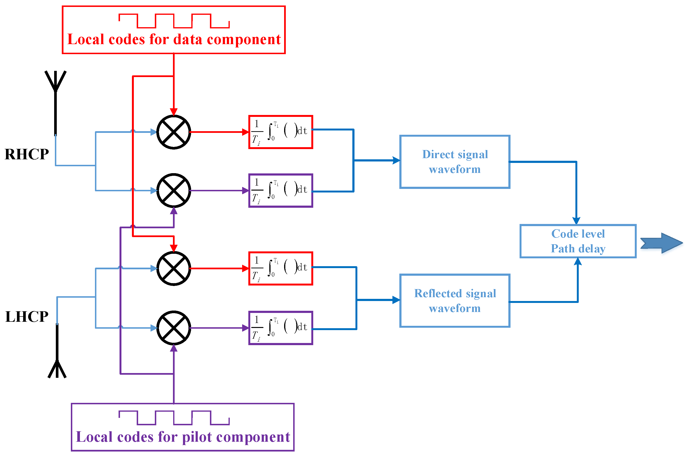
Raw IF data of direct and reflected signals were processed to obtain the code-level path delay measurements using a software-defined receiver (SDR) modified from an open source code using MATLAB [19]. Figure 1 shows a brief flow chart of this GNSS-R SDR. Firstly, both the direct and reflected signals are cross-correlated separately with the pilot and data local replicas. The coherent span for both B1C and B2a codes is 10 milliseconds; each signal produces two waveforms because of its pilot and data components. In order to increase the signal-to-noise ratio, the two values added incoherently by power ratios are the direct signal waveform and reflected signal waveform. Then, the code-level path delays are computed from the positions of waveform peaks by applying cubic spline interpolations. Furthermore, in order to increase the stability and precision, we computed 21 path delays in one second at intervals of 50 milliseconds and selected their median value for further processing. Finally, the reflector heights from the sea surface are calculated in accordance with the geometry of ground-based GNSS-R altimetry.
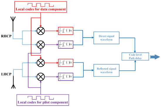
Figure 1.
Basic concept of deriving code-level path delay from waveforms of direct and reflected signals using the data component (red) and the pilot component (purple).
3. Experiments
Our GNSS-R IF data collection system is mainly composed of two dual-circularly polarized crossed dipole antennas and one raw data recorder with four radio frequency signal input ports. Two of them are for the direct and reflected signals from the B1 band while the other two are for the B2 band. The bandwidths of the recorder are 20.46 MHz; its central frequencies are at 1529 MHz and 1130 MHz for the two kinds of signals, respectively. The IF data are quantified with 2 bits and recorded at a sampling rate of 62 MHz continuously in most cases. The data are then transferred to a laptop through a USB 3.0 cable.
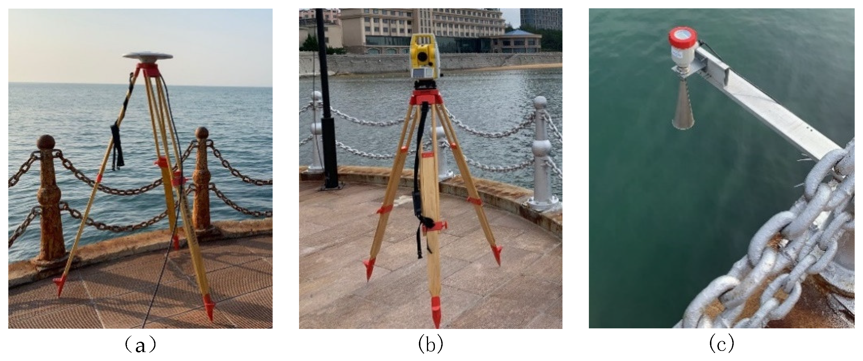
Apart from GNSS-R setups, a geodetic GNSS receiver, chock-ring antenna, and an electronic total station were used to obtain the geodetic height of the GNSS-R antennas. An independent 26 GHz radar altimeter was installed on the trestle, which can provide vertical distance from the sea surface to its phase center with 3 mm accuracy every second. We measured the precise height differences among the phase centers of the chock-ring GNSS antenna, GNSS-R antenna, and radar altimeter using the electronic total station. Figure 2 shows the relevant photos.
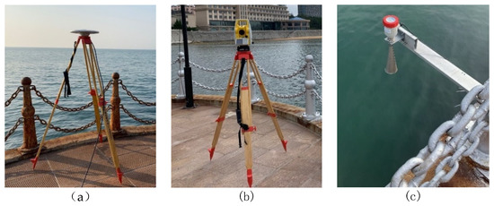
Figure 2.
Photos of the geodetic GNSS chock-ring antenna (a), electronic total station (b), and the monostatic radar altimeter (c).
We performed the experiment on a shore trestle bridge located at Weihai in Shandong province with latitude and longitude coordinates (37°32′2.62″ N, 122°2′44.11″ E) on November 5, 2020. An upward GNSS-R antenna was used for receiving direct signals with right-handed circular polarization while the down-looking one was for reflected signals with left-handed circular polarization. As the operating band of the antennas ranged from 1.16 to 1.62 GHz, it can cover B1C and B2a signals. Before entering the recorder, both of the direct and reflected signals are spilt into two channels by two two-way power dividers. One is for B1C and another is for B2a. The configuration of antennas and the satellite image of the trestle bridge are shown in Figure 3 and the tilt angles of the antennas are both 30° to horizontal. Their phase centers are in a single plumb line. The height of the antennas above the sea surface ranged from about three to five meters during our experiment. In addition, as the beam width angle of the antennas is 60°, the available satellite elevation ranges from 30° to 90° for this experiment. The two antennas faced south to receive more reflected signals, and so the available satellite azimuth ranged from 150° to 210°.

Figure 3.
The configuration of antennas for our GNSS-R altimetry experiment (a), the photograph of the antennas’ arrangement (b) and top view of the trestle bridge (c) during the experiment.
4. Results
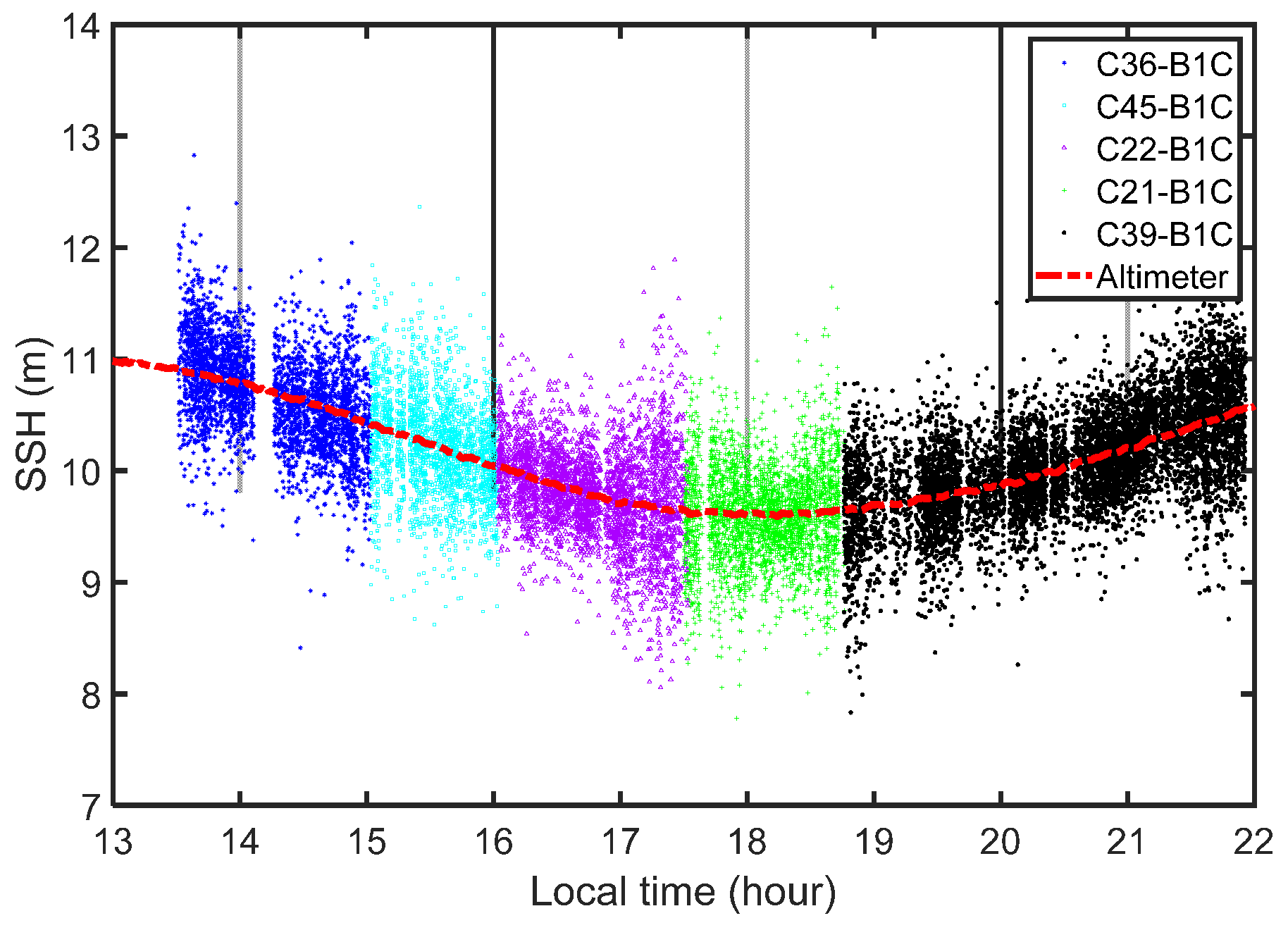
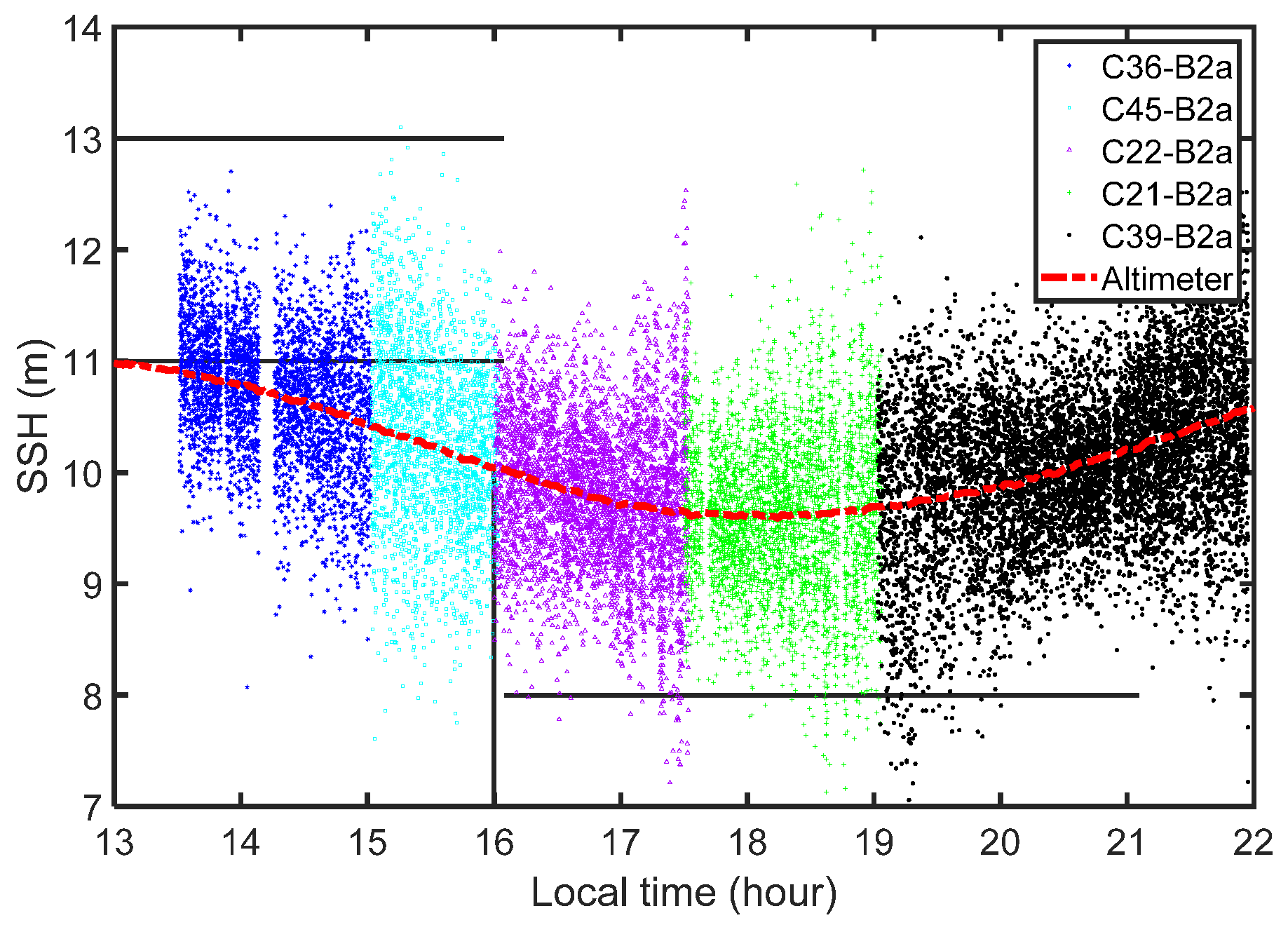
The signals from five different satellites, including four MEOs and an IGSO, were used for computing reflector heights at different periods. The SSHs were separately derived, based on B2a and B1C signals from 13:30 to 22:00 on 5 November (local time). In general, continuous GNSS-R altimetry solutions were achieved for more than eight hours. As the reflector heights could be derived by using the code-level path delay measurements of one satellite, we selected signals from only one satellite over a certain period of time. The sea surface was smooth in general during the experiment, so the path delay measurements were derived from the peak point positions of the direct and reflected waveforms. As the coherence time for both B1C and B2a codes was 10 milliseconds, each time slot of 10 milliseconds produced an estimate of the path delay. Considering that our SDR runs very slow, we computed a delay measurement every 50 milliseconds to save time. So, there are 21 delays in one second, and their median value was chosen for altimetry retrievals. Figure 4 and Figure 5 show SSHs derived from B1C and B2a code-level delay measurements, respectively. We find that the solutions of both B1C and B2a can reflect the trend of the sea surface change, compared with the measurements of the radar altimeter. However, the noise level of B2a is larger than that of B1C. It should be noted that the gaps around 14:10 in Figure 4 and Figure 5 were caused by an accidental interruption in the power supply at the beginning of our experiment.
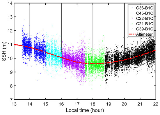
Figure 4.
SSHs derived from B1C code-level delay and radar altimeter measurements for more than eight hours.
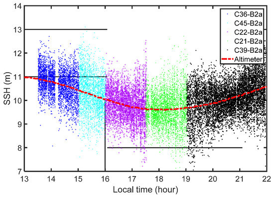
Figure 5.
SSHs derived from B2a code-level delay and radar altimeter measurements for more than eight hours.
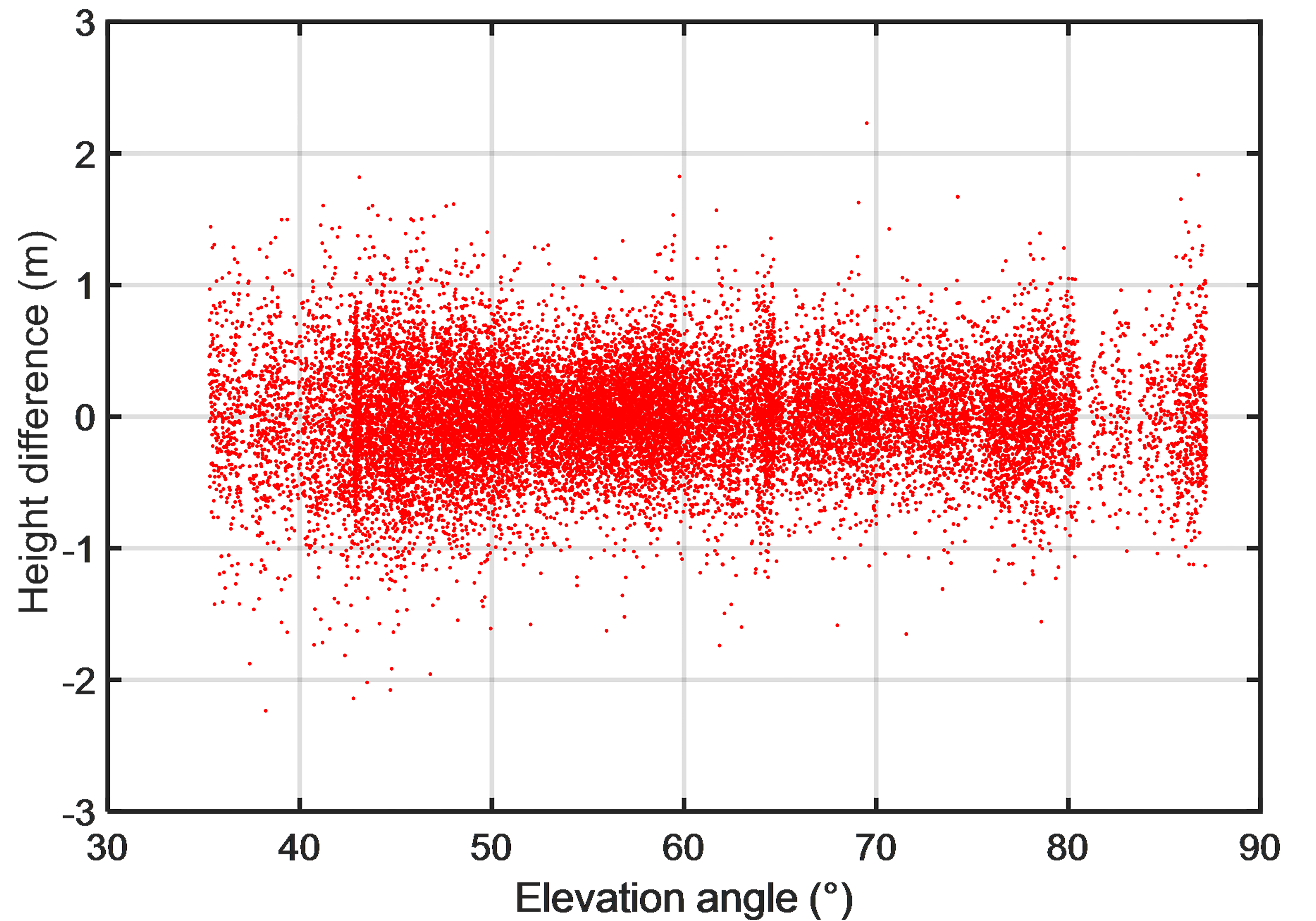
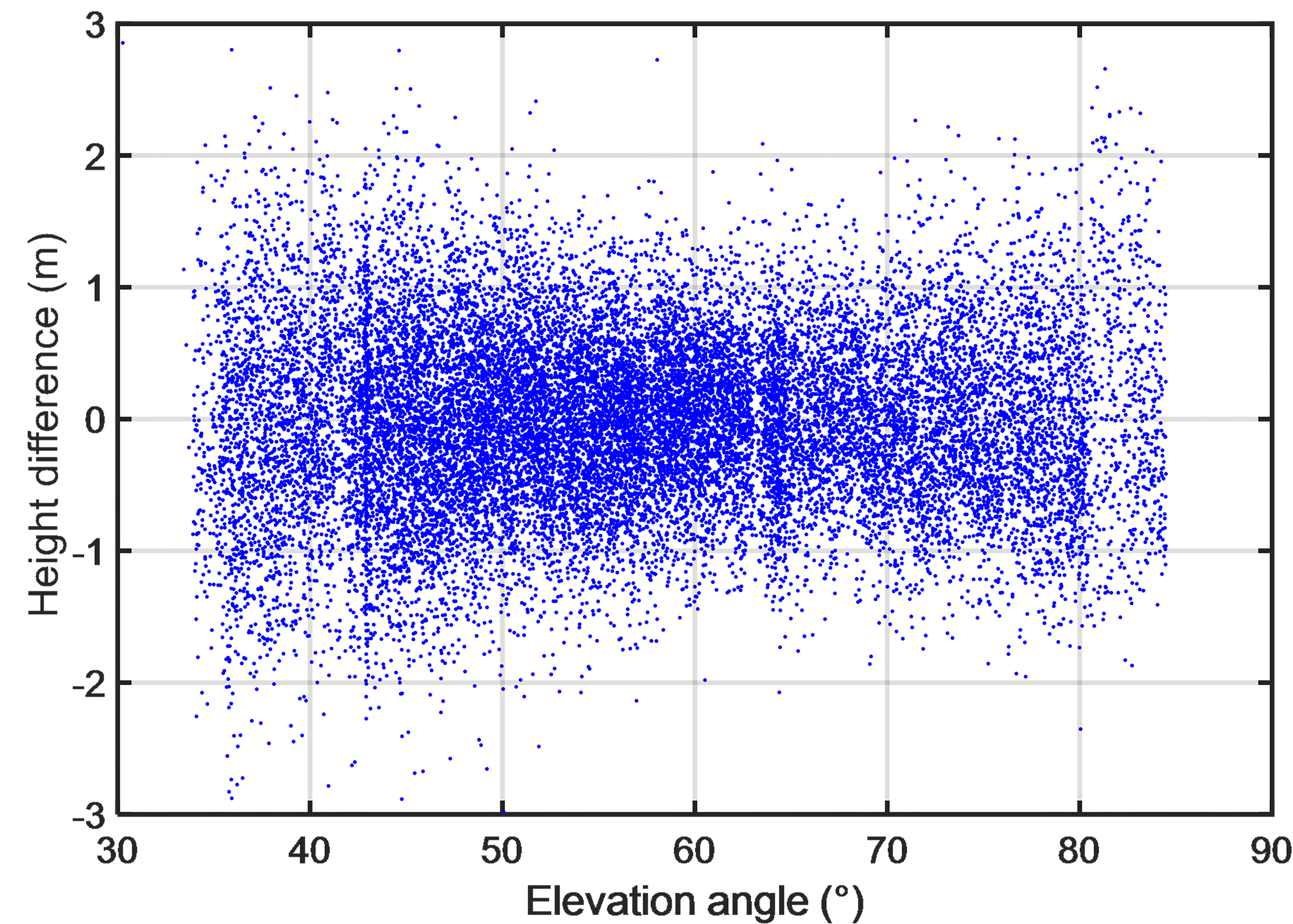
In order to evaluate the precision of GNSS-R altimetry based on the two kinds of new BDS civil codes, we differentiated between the solutions and radar altimeter measurements. Figure 6 and Figure 7, respectively, show their height difference sequence with the satellite elevation angles for B1C and B2a signals. The root mean square (RMS) values of the two sequences are 0.394 m and 0.668 m for B1C and B2a, which are better than the solutions derived from GPS C/A and BDS B1I code [20]. It is worth noting that the divergence is a minimum of between 60° and 70° in both the cases. This is because the signals with elevation angles around 60° have small incidence angles for both upward- and downward-looking antennas, thanks to their 30° tilted angles. The gain of antennas is maximal in these directions, indicating that higher gain of antenna will help improve the precision of the solutions. On the other hand, both the direct and reflected signals with higher elevations have higher power, so that the divergence is a minimum of around 65° instead of 60°.
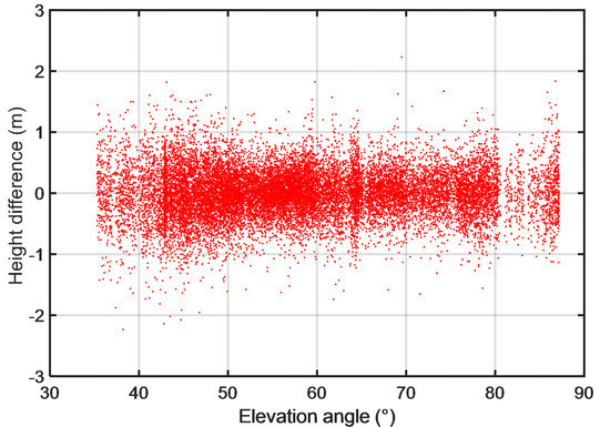
Figure 6.
Differences between measured SSHs using monostatic radar and B1C signals at different elevations.
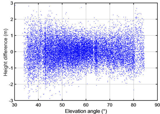
Figure 7.
Differences between measured SSHs using monostatic radar and B2a signals at different elevations.
The above analysis shows that the precision of GNSS-R code-delay altimetry achieved from B1C is better than that from B2a. In this study, the coherent time is 10 milliseconds for both signals. The code rate of B2a signals is 10 times that of B1C, but the complicated code construction of B1C produces its wider bandwidth compared to B2a. In addition, the results of a positioning experiment using BDS-3 signals showed that B2a signals have relatively poor quality, although they have stronger power than the other open available ranging code [21]. Affected by the above factors, GNSS-R code-delay altimetry based on B2a signals from our experiment has worse precision than that based on B1C signals.
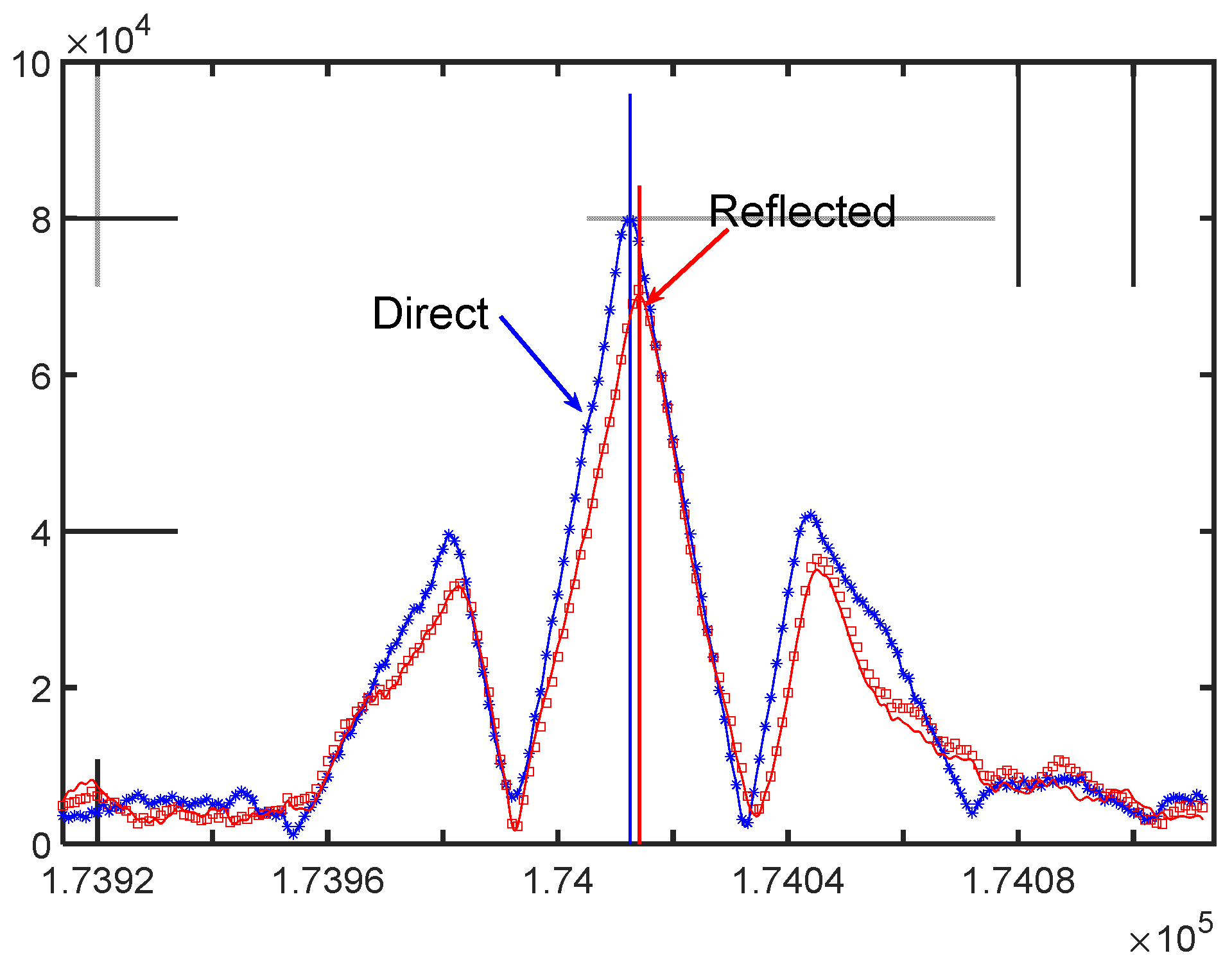
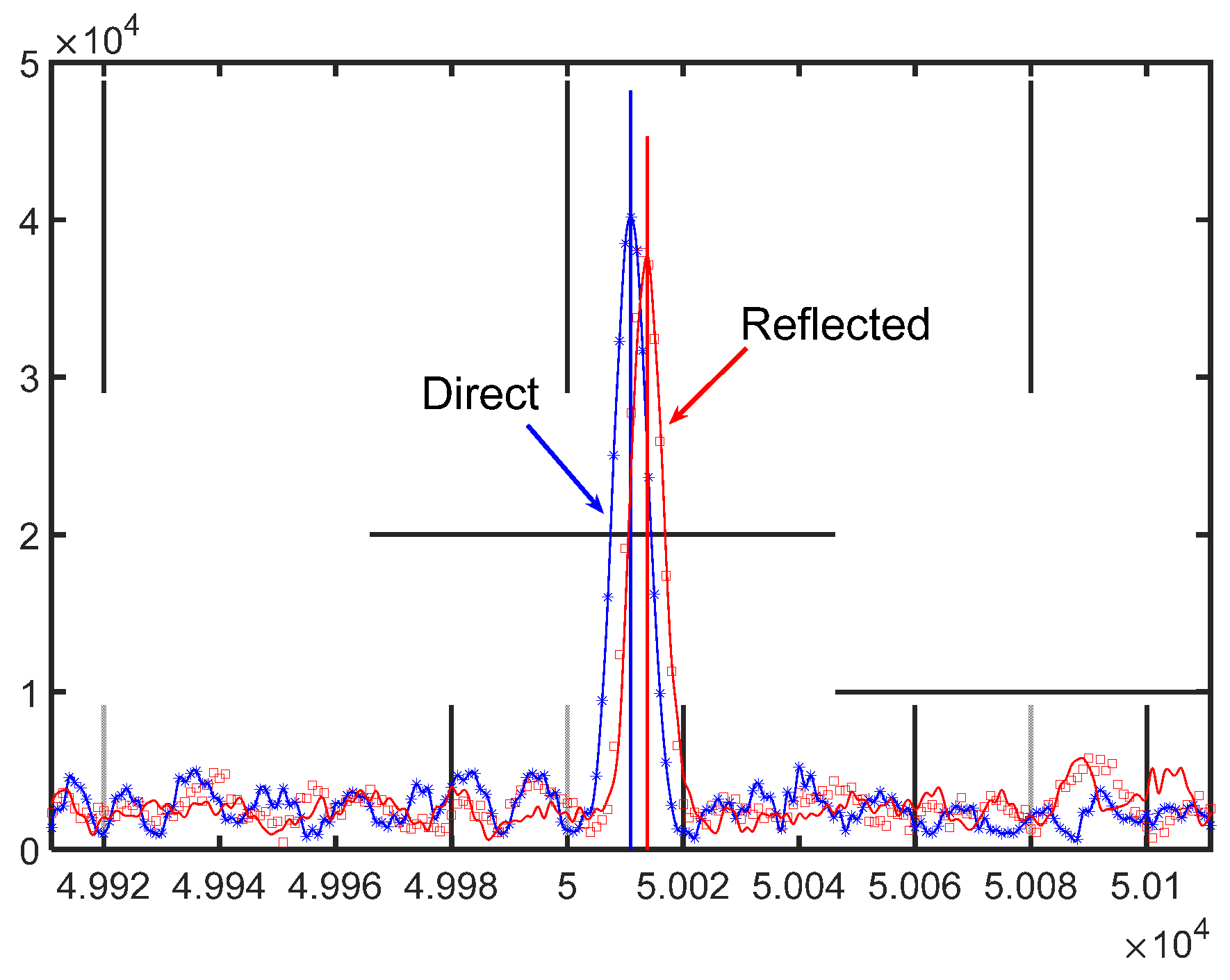
Since our altimetry solutions are derived from the differential measurement of the direct and reflected code ranges, we investigated the cross-correlated waveforms of the two new BDS-3 civil signals for further exploration. Figure 8 and Figure 9, respectively, show the waveforms of B1C and B2a codes for direct and reflected signals. During the experiment, the sea surface had no appreciable roughness and the reflector heights ranged from three to five meters, so that the path delays can be calculated from the peak positions of the waveforms [6]. From Figure 8 and Figure 9, the direct and reflected B2a waveforms are about half of the B1C ones. This may be caused by its poor signal quality and narrower bandwidth.
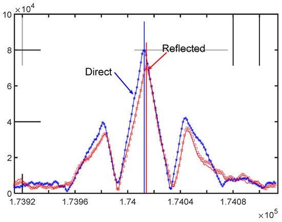
Figure 8.
Cross-correlated waveforms of B1C code for direct (blue) and reflected (red) signals.
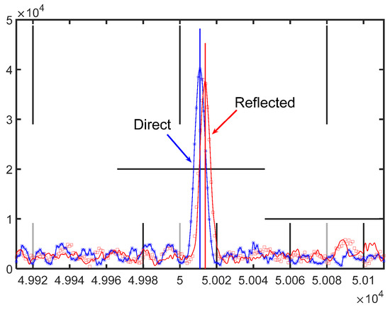
Figure 9.
Cross-correlated waveforms of B2a code for direct (blue) and reflected (red) signals.
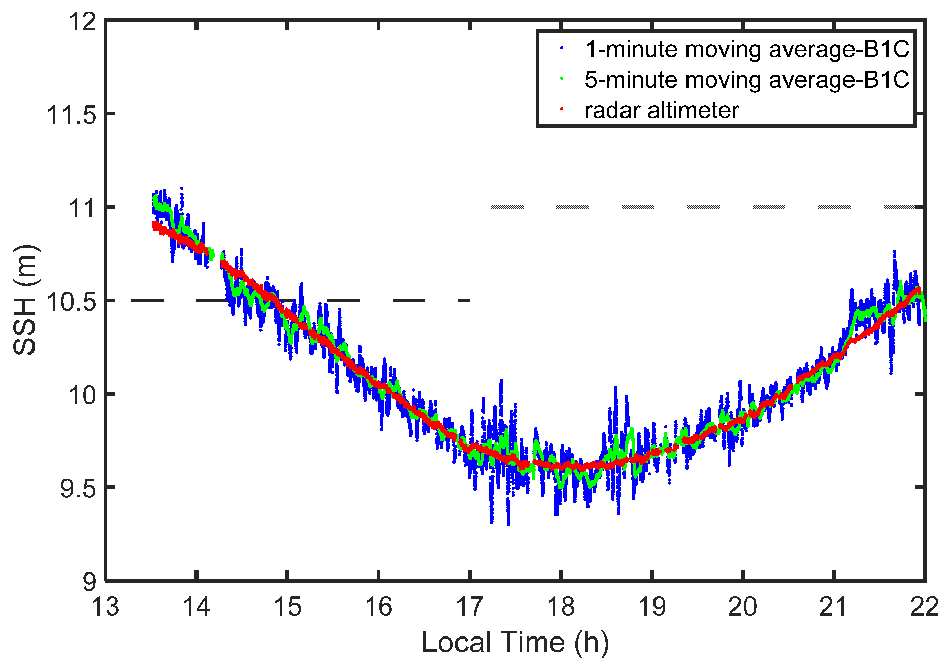
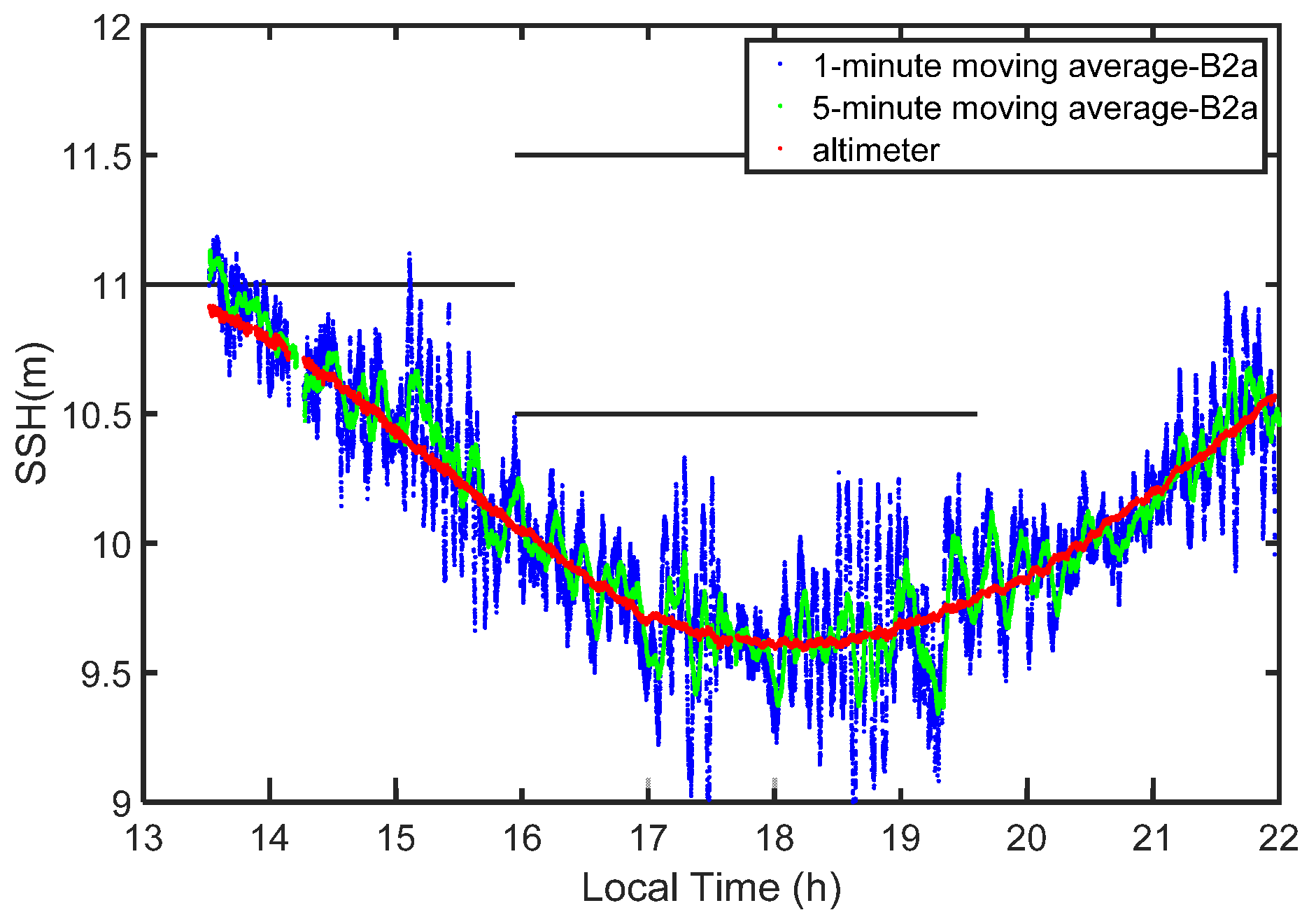
Centimeter-level SSH measurements are widely required for many geoscience applications. Obviously, the original solutions derived from B1C and B2a cannot directly satisfy this requirement. However, as BDS-3 has completed its full operations, an adequate number of satellites could be observed for GNSS-R altimetry during our experiment. Their SSH measurements could be obtained continuously and so the change of actual SSH was a steady dynamic process. In this paper, moving averages with windows of one minute and five minutes were applied to smoothing solutions derived from B1C and B2a signals. In Figure 10 and Figure 11, the red points stand for the SSH obtained from radar altimeter; the blue ones stand for those after applying a one-minute moving average; green ones stand for those after applying a five-minute moving average. The results indicated that the precision improved a lot in both cases.
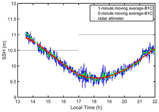
Figure 10.
SSHs derived from B1C code-level delay measurements with moving average and radar altimeter for more than eight hours.
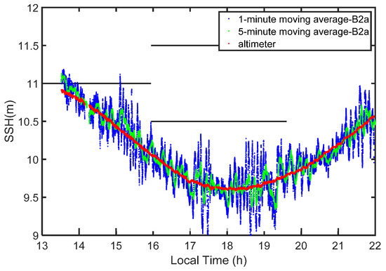
Figure 11.
SSHs derived from B2a code-level delay measurements with moving average and radar altimeter for more than eight hours.
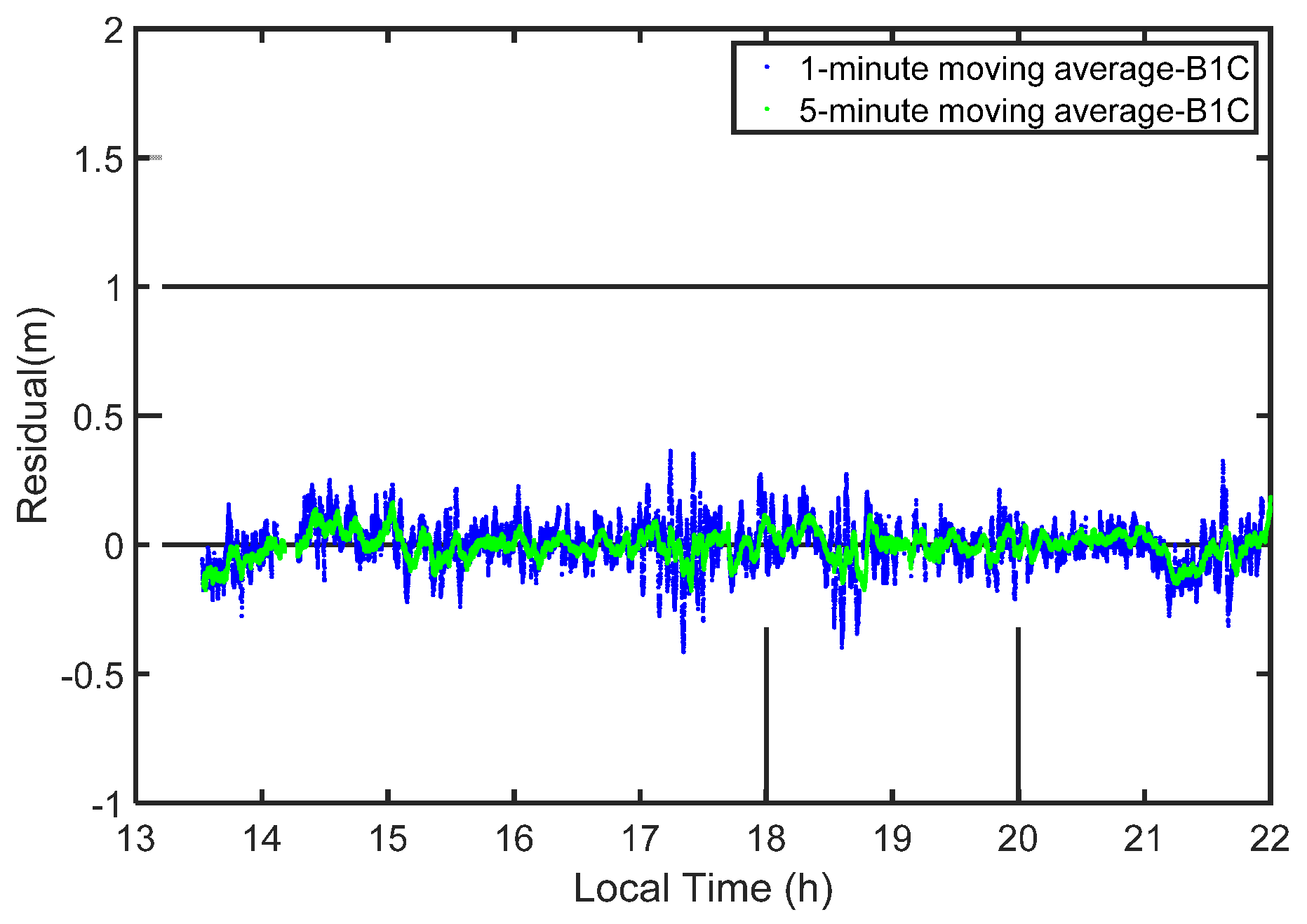
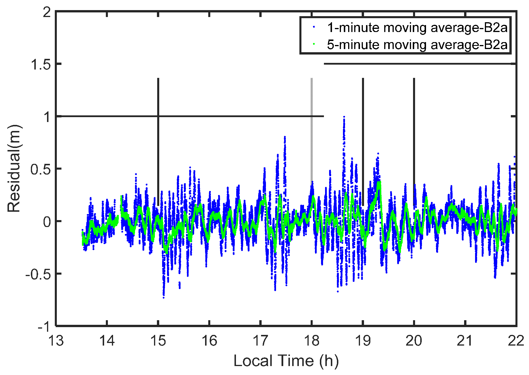
In order to evaluate the performance of the filters, we differentiated between the solutions and measurements of the radar altimeter. Figure 12 and Figure 13 show the residuals. The RMSs of B1C-based SSH are 0.090 m and 0.053 m for one-minute and five-minute moving averages while those for B2a case are 0.199 m and 0.111 m. The final results show that centimeter-level SSH can be achieved using the B1C signal, while the precision for the B2a case can only reach the decimeter level.
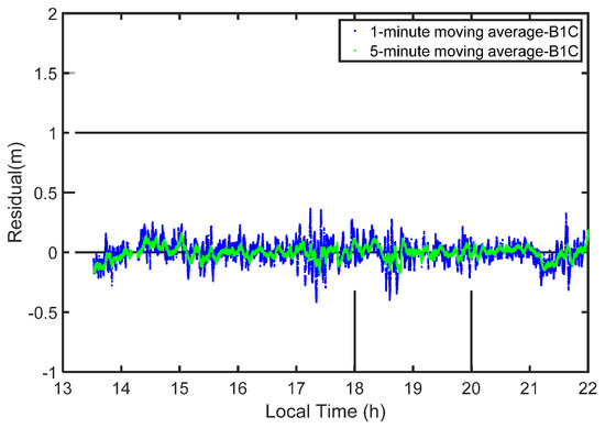
Figure 12.
Differences between measured SSHs using monostatic radar and smoothed solutions from B1C signals.
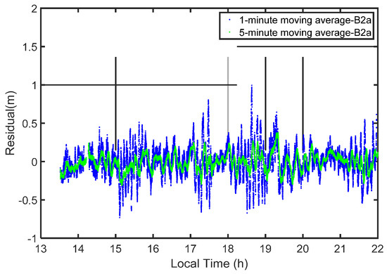
Figure 13.
Differences between measured SSHs using monostatic radar and smoothed solutions from B2a signals.
5. Discussion
GNSS-R is a promising and low-cost technique for ocean altimetry on different platforms. New GNSS signals, designed with better performance, bring opportunities for improving the accuracy and precision. We tested the performance of GNSS-R code-level altimetry based on new BDS-3 civil codes by conducting a coastal experiment for the first time. The solutions derived from B1C and B2a signals are achieved at one second intervals for a period of about eight hours. The final results show that the centimeter-level precision of GNSS-R altimetry based on B1C codes can be achieved; it is similar to that of the tide gauge.
Our results demonstrated that the precision of solutions from the two new civilcodesare higher than those from conventional GPS C/A and BDS B1I. Furthermore, the solutions from B1C are better than those from B2a. The poor performance of the single-frequency band B2a was attributed to its poor signal quality and narrower bandwidth. In addition, we also found that the precision of the solutions can be affected by signal power.
One of a main feature of BDS-3 is its hybrid constellation, in which the GEO satellites can provide stable geometries for GNSS-R observations. However, in this paper, no solution was retrieved from the signals of the BDS-3 GEO satellite. They provide fundamental PNT service on the legacy B1I and B3I signals, while new B1C and B2a signals are used for providing SABS service. Unfortunately, their SABS services are still in testing. As the GNSS-R code-level altimetry performance of BDS-3 B1C and B2a signals is studied, we could not test BDS-3 GEO signals during this experiment.
In this work, the performance of GNSS-R altimetry based on the B1C and B2a signals was only tested on a very low platform when the sea surface was in a good condition. We plan to conduct experiments on higher platforms, such as using an unmanned aerial vehicle and/or plane to investigate their characteristics. We should find a proper and safe place to conduct experiments for different sea states.
The monostatic radar altimeter can accurately measure the vertical distance from its phase center to the sea surface, which enabled us to obtain the precise reflector height. In this work, we solved a bias for each satellite using the precise reflector height values. This is because the biases are caused not only by the sea surface roughness and the electromagnetic characters, but are also affected by the signal bandwidth and instrumental reasons [22,23,24]. So, further explorations for the biases require much more data over a long time. However, as our SDR runs very slowly and the IF data are too large to be stored, we cannot process and analyse long-time data in this work.
Author Contributions
Conceptualization, F.G., T.X. and N.W.; methodology, F.G., X.M.; software, F.G., X.M. and Y.H.; validation, N.W., X.M. and Y.H. and B.N.; formal analysis, F.G.; investigation, F.G., X.M. and Y.H. and B.N.; resources, F.G., X.M. and Y.H. and B.N.; data curation, X.M. and Y.H. and B.N.; writing—original draft preparation, F.G.; writing—review and editing, F.G., T.X. and N.W.; visualization, F.G.; supervision, T.X.; project administration, T.X.; funding acquisition, F.G., T.X. and N.W. All authors have read and agreed to the published version of the manuscript.
Funding
This research was jointly funded by the National Key Research and Development Program of China (2016YFB0501701) and the Program of the National Natural Science Foundation of China (41604003, 41704017, 41704018).
Data Availability Statement
The datasets analyzed in this study are managed by Institute of Space Science, Shandong University and can be made available by the corresponding author on request.
Acknowledgments
The authors thank the staff of Weihai Golden Bay Hotel who kindly provided help during the experiment.
Conflicts of Interest
The authors declare no conflict of interest.
References
- Ablain, M.; Cazenave, A.; Larnicol, G.; Balmaseda, M.; Cipollini, P.; Faugère, Y.; Fernandes, M.J.; Henry, O.; Johannessen, J.A.; Knudsen, P. Improved sea level record over the satellite altimetry era (1993–2010) from the Climate Change Initiative project. Ocean Sci. Discuss. 2015, 11, 2029–2071. [Google Scholar] [CrossRef]
- Xu, Q.; Tu, K.; Cheng, Y.; Wang, W.; Jia, Y.; Ye, X. Satellite Altimetry and Tide Gauge Observed Teleconnections between Long-Term Sea Level Variability in the U.S. East Coast and the North Atlantic Ocean. Remote Sens. 2019, 11, 2816. [Google Scholar] [CrossRef]
- Martín-Neira, M. A Passive reflectometry and interferometry system (PARIS): Application to ocean altimetry. ESA J. 1993, 17, 331–335. [Google Scholar]
- Pascual, D.; Camps, A.; Martin, F.; Park, H.; Arroyo, A.A.; Onrubia, R. Precision bounds in GNSS-R ocean altimetry. IEEE J. Sel. Top. Appl. Earth Observ. Remote Sens. 2014, 7, 1416–1423. [Google Scholar] [CrossRef]
- Martin-Neira, M.; Caparrini, M.; Font-Rossello, J.; Lannelongue, S.; Vallmitjana, C.S. The PARIS concept: An experimental demonstration of sea surface altimetry using GPS reflected signals. IEEE Trans. Geosci. Remote Sens. 2001, 39, 142–150. [Google Scholar] [CrossRef]
- Rius, A.; Nogués-Correig, O.; Ribó, S.; Cardellach, E.; Oliveras, S.; Valencia, E.; Park, H.; Tarongí, J.M.; Camps, A.; van der Marel, H.; et al. Altimetry with GNSS-R interferometry: First proof of concept experiment. GPS Solut. 2012, 16, 231–241. [Google Scholar] [CrossRef]
- Zhang, Y.; Tian, L.; Meng, W.; Gu, Q.; Han, Y.; Hong, Z. Feasibility of code-level altimetry using coastal BeiDou reflection (BeiDou-R) setups. IEEE J. Sel. Top. Appl. Earth Observ. Remote Sens. 2015, 8, 4130–4140. [Google Scholar] [CrossRef]
- Lowe, S.T.; Zuffada, C.; Labrecque, J.L.; Lough, M.; Young, L.E. An ocean-altimetry measurement using reflected GPS signals observed from a low-altitude aircraft. In Proceedings of the IEEE 2000 International Geoscience and Remote Sensing Symposium, Honolulu, HI, USA, 24–28 July 2000. [Google Scholar]
- Lowe, S.T.; Zuffada, C.; Chao, Y.; Kroger, P.; Young, L.E.; Labrecque, J.L. 5-cm-precision aircraft ocean altimetry using GPS reflections. Geophys. Res. Lett. 2002, 29, 1375. [Google Scholar] [CrossRef]
- Cardellach, E.; Rius, A.; Martin-Neira, M.; Fabra, F.; Nogues-Correig, O.; Ribo, S.; Kainulainen, J.; Camps, A.; D”Addio, S. Consolidating the precision of interferometric GNSS-R ocean altimetry using airborne experimental data. IEEE Trans. Geosci. Remote Sens. 2014, 52, 4992–5004. [Google Scholar] [CrossRef]
- Li, W.; Rius, A.; Fabra, F.; Cardellach, E.; Martin-Neira, M. Revisiting the GNSS-R Waveform Statistics and Its Impact on Altimetric Retrievals. IEEE Trans. Geosci. Remote Sens. 2018, 56, 2854–2871. [Google Scholar] [CrossRef]
- Clarizia, M.P.; Ruf, C.; Cipollini, P.; Zuffada, C. First spaceborne observation of sea surface height using GPS-reflectometry. Geophys. Res. Lett. 2016, 43, 767–774. [Google Scholar] [CrossRef]
- Li, W.; Cardellach, E.; Fabra, F.; Ribó, S.; Rius, A. Assessment of Spaceborne GNSS-R Ocean Altimetry Performance Using CYGNSS Mission Raw Data. IEEE Trans. Geosci. Remote Sens. 2020, 58, 238–250. [Google Scholar] [CrossRef]
- Li, W.; Cardellach, E.; Serni, R.; Rius, A.; Zhou, B. First spaceborne demonstration of BeiDou-3 signals for GNSS reflectometry from CYGNSS constellation. Chin. J. Aeronaut. 2021, (in press). [CrossRef]
- Li, W.; Cardellach, E.; Fabra, F.; Ribó, S.; Rius, A. Lake Level and Surface Topography Measured with Spaceborne GNSS-Reflectometry from CYGNSS Mission: Example for the Lake Qinghai. Geophys. Res. Lett. 2018, 45, 13,332–13,341. [Google Scholar] [CrossRef]
- Yang, Y.; Mao, Y.; Sun, B. Basic performance and future developments of BeiDou global navigation satellite system. Satell. Navig. 2020, 1, 1–8. [Google Scholar] [CrossRef]
- BeiDou Navigation Satellite System Signal in Space Interface Control Document Open Service Signal B2a (Version 1.0). Available online: http://www.beidou.gov.cn/xt/gfxz/201712/P020171226742357364174.pdf (accessed on 27 December 2017).
- BeiDou Navigation Satellite System Signal in Space Interface Control Document Open Service Signal B1C (Version 1.0). Available online: https://www.beidou.gov.cn/xt/gfxz/201712/P020171226741342013031.pdf (accessed on 24 October 2019).
- Li, Y.; Shivaramaiah, N.C.; Akos, D.M. Design and implementation of an open-source BDS-3 B1C/B2a SDR receiver. GPS Solut. 2019, 23, 60. [Google Scholar] [CrossRef]
- Gao, F.; Xu, T.; Wang, N.; He, Y.; Luo, X. A shipborne experiment using a dual-antenna reflectometry system for GPS/BDS code delay measurements. J. Geod. 2020, 94, 88. [Google Scholar] [CrossRef]
- Yuan, Y.; Mi, X.; Zhang, B. Initial assessment of single and dual-frequency BDS-3 RTK positioning. Satell. Navig. 2020, 1, 1–7. [Google Scholar] [CrossRef]
- Rius, A.; Cardellach, E.; Martin-Neira, M. Altimetric Analysis of the Sea-Surface GPS-Reflected Signals. IEEE Trans. Geosci. Remote Sens. 2010, 48, 2119–2127. [Google Scholar] [CrossRef]
- Zavorotny, V.U.; Gleason, S.; Cardellach, E.; Camps, A. Tutorial on Remote Sensing Using GNSS Bistatic Radar of Opportunity. IEEE Trans. Geosci. Remote Sens. Mag. 2014, 2, 8–45. [Google Scholar] [CrossRef]
- Ghavidel, A.; Schiavulli, D.; Camps, A. Numerical Computation of the Electromagnetic Bias in GNSS-R Altimetry. IEEE Trans. Geosci. Remote Sens. 2016, 54, 489–498. [Google Scholar] [CrossRef]
Publisher’s Note: MDPI stays neutral with regard to jurisdictional claims in published maps and institutional affiliations. |
© 2021 by the authors. Licensee MDPI, Basel, Switzerland. This article is an open access article distributed under the terms and conditions of the Creative Commons Attribution (CC BY) license (https://creativecommons.org/licenses/by/4.0/).

