Abstract
Global navigation satellite system (GNSS) array antenna receivers are widely used to suppress wideband interference in navigation countermeasures. However, existing array antenna receivers all adopt a digital array structure and digital beamforming technique, and they have limited analog-front-end (AFE) dynamic range. In strong interference scenarios, AFE saturation will occur, which limits the maximum interference suppression ability of the array receiver. Aiming at this issue, this paper proposes a robust wideband interference suppression method for GNSS array antenna receivers based on a hybrid beamforming technique. Firstly, a novel, fully connected hybrid array receiver structure is proposed. Secondly, the corresponding hybrid beamforming method is proposed at the same time, and it realizes the complete elimination of the strong wideband interference by joint suppression in the analog domain and digital domain. After mathematical simulations, it is verified that, compared to the digital beamforming-based anti-jamming technique, the proposed method can effectively suppress strong wideband interference, and the maximum interference suppression ability is improved by 36 dB.
1. Introduction
The global navigation satellite system (GNSS) has the characteristics of all-weather and all-time, and it is widely used in various fields of society to obtain position, velocity, and time (PVT) information [1]. Due to the low power of GNSS signals, they are highly susceptible to various intentional or unintentional interferences [2]. In order to ensure the effective performance of GNSS receivers in harsh civilian and military environments, various anti-jamming techniques have been developed. They eliminate narrowband and wideband interference in the time domain and space domain [3,4].
However, various anti-jamming techniques can only be effectively implemented when the receiver analog-front-end (AFE, including the antenna, radio frequency (RF), and analog-to-digital converter (ADC) in a broad sense) responds linearly to the input combination of signal, noise, and interference [5]. As a weak link, the AFE of GNSS receivers is susceptible to nonlinear effects such as saturation that distort the input waveforms due to the strong interference received [6,7]. AFE saturation is an extreme case of the interference effect in strong interference scenarios. The linear dynamic range of the AFE sets the maximum interference suppression ability of the anti-jamming techniques [8]. Therefore, how to relax the linear dynamic range of the receiver AFE to prevent saturation in strong interference scenarios is of great significance to improving the anti-jamming performance of the receiver.
In recent years, some techniques have been developed to deal with AFE saturation issues in GNSS receivers. The paper [9] proposes stopband filtering techniques to alleviate saturation caused by out-of-band and near-band interference. Paper [10] proposes two antenna modules composed of dynamically configured component topology networks. These two configurable antenna modules can detect, identify, and isolate potential interference. They switch modules with different gains based on the detected interference power to prevent AFE saturation. In the literature [11], an ideal and very slow automatic gain control (AGC) is placed at the AFE to prevent AFE saturation when continuous wave interference occurs. Papers [10,11] both ensure that the AFE does not experience saturation in strong interference scenarios by adaptively adjusting the AFE gain. However, all the methods mentioned above for dealing with AFE saturation focus on narrowband interference, and they are mainly applied to single antenna receivers. The methods for dealing with saturation caused by the strong wideband interference are rarely mentioned, and they are mainly applied to array antenna receivers. Firstly, wideband interference belongs to in-band interference, and the stopband filtering technology in the literature [9] cannot be used to prevent AFE saturation. Secondly, wideband interference is mostly intentional interference, and it has a greater interference power than narrowband interference, which mostly belongs to unintentional interference. Excessive AFE gain adjustment in the literature [10,11] may lead to insufficient amplification of weak GNSS signals, and the ADC sampled signal cannot obtain a sufficient signal-to-noise ratio (SNR). Therefore, the existing AFE saturation processing methods cannot be used in a strong wideband interference scenario.
There is some literature on the AFE saturation processing methods caused by the strong wideband interference in radar and communication fields. Paper [12] proposes a hybrid beamforming method to filter out the strong interference. A phase shifter array is added to the AFE of the antenna subarray, and the strong interference is jointly suppressed in the analog domain and the digital domain. Papers [13,14] propose a fully connected hybrid array chip design method for a massive multiple-input multiple-output (MIMO) system, and it prevents AFE saturation by suppressing interference in the analog domain. Papers [15,16] propose a hybrid array form with a fully connected structure and a hybrid beamforming method. The high-power wideband self-interference signal is suppressed in both the analog and digital domains. However, the aforementioned hybrid beamforming method still cannot be used in GNSS array antennas. Firstly, the GNSS array is a small aperture array, and it has a limited number of antennas [17]. Thus, the method proposed for antenna subarray in the literature [12,13,14] is not applicable to GNSS array antennas. Secondly, the receiver only receives but does not transmit signals, and the prior information of the interference signal waveform cannot be obtained, so the method proposed in the literature [15,16] cannot be adopted either.
Aiming at the AFE saturation caused by the intentional strong wideband interference in the GNSS array antenna, a hybrid beamforming technique is proposed that simultaneously performs interference suppression in the analog domain and digital domain. Firstly, a novel, fully connected hybrid array anti-jamming receiver structure is proposed. Secondly, the corresponding hybrid beamforming technique is proposed at the same time. In the analog domain, multiple different 2D spatial analog notch filters are used to partially suppress interference and prevent AFE saturation. In the digital domain, the existing digital beamforming-based anti-jamming technique is calibrated and used to filter out residual interference.
The remainder of this paper is organized as follows: The second section briefly introduces the signal model and digital beamforming-based anti-jamming technique; the third section proposes the hybrid beamforming technique, which includes analog beamforming technique and digital beamforming technique; the fourth section gives the mathematical simulation results; and finally, the fifth section gives some conclusions about this paper.
2. Signal Model and Conventional Anti-Jamming Technique
In this section, the signal model of the anti-jamming receiver is first introduced, and then two conventional anti-jamming methods based on the digital beamforming technique are introduced.
2.1. Signal Model
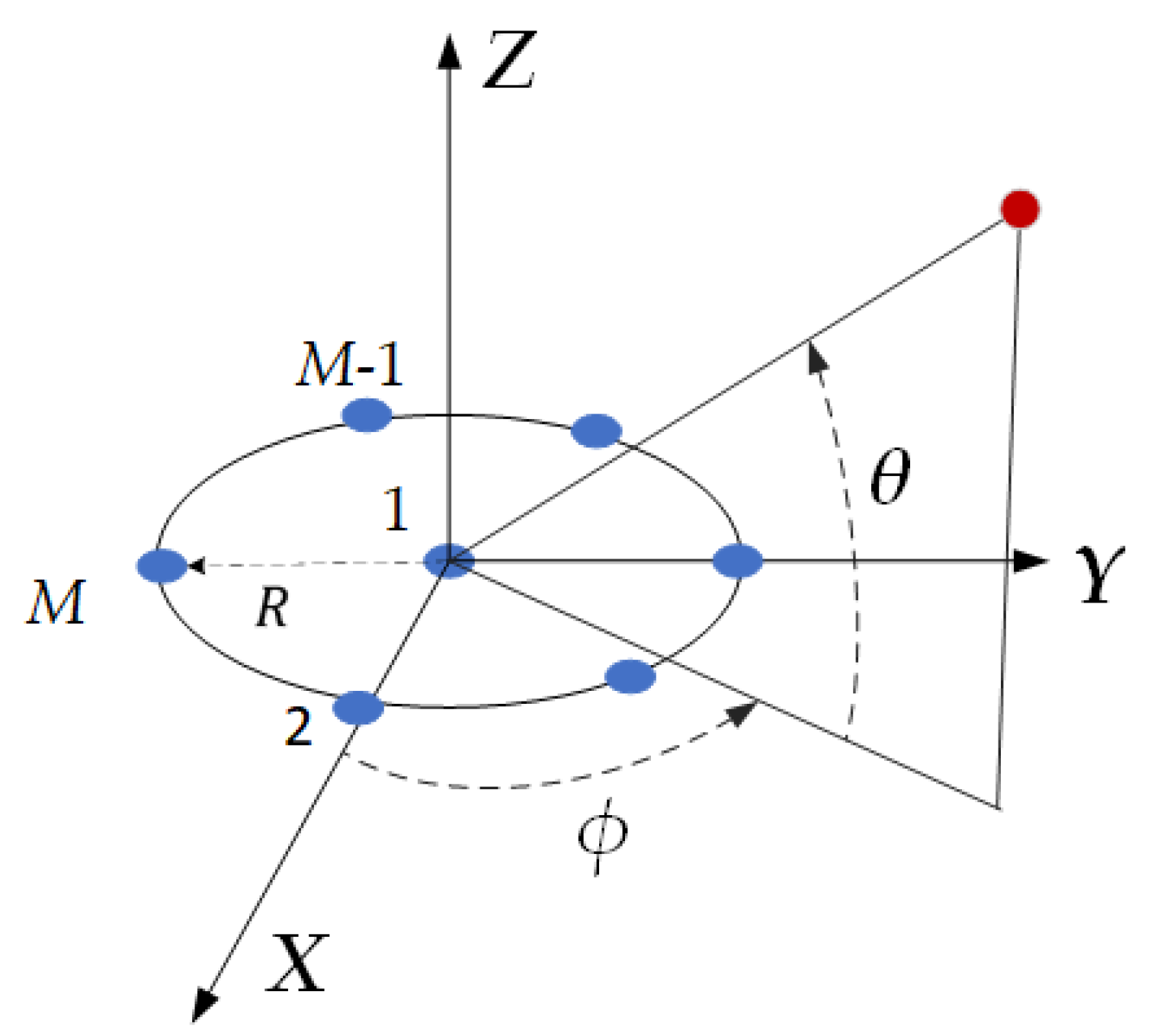
The GNSS array antenna receiver generally adopts a small aperture circular array, as shown in Figure 1. The array is composed of M isotropic elements. Without loss of generality, assuming there is one GNSS signal and Q interference signals received by the array antenna, the array form of the received signal can be represented as follows:
where t is the time, is the array snapshot with M-element array antennas. is the GNSS signal, is the q-th interference signal, and Q is the number of interferences. denotes the 2D angle , i.e., ; and represent elevation and azimuth, respectively. and are the steering vectors of GNSS signal and interference signal , respectively, and is the additive white noise vector.
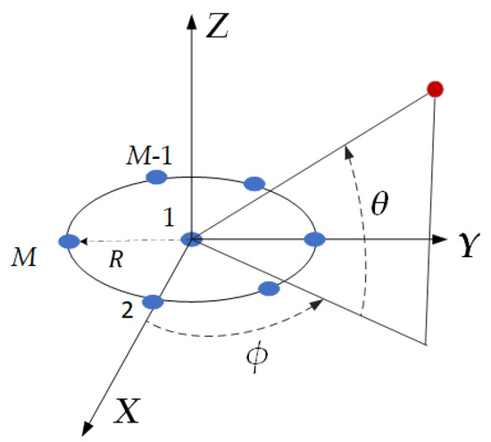
Figure 1.
GNSS array antenna receiver configuration.
The steering vector of the array in Equation (1) can be represented as follows:
where
Here, , represents the wavelength corresponding to GNSS signal center frequency f, i.e., ; the denotes the pattern radiated by each element. Here, to simplify the derivation process, is adopted.
2.2. Digital Beamforming-Based Anti-Jamming Processing Technique
In order to suppress interference in Equation (1), a weight vector w is applied to the received signal vector, and the output signal of the array is shown below.
where is the conjugate transpose operation, and denotes the signal after ADC sampling.
In the field of conventional digital beamforming-based anti-jamming processing techniques, there are two techniques for obtaining the weight w: the minimum variance distortionless response (MVDR) technique and the power inversion (PI) technique [18,19].
The MVDR technique is widely used in various fields, and its objective function is as follows:
where represents the covariance matrix of the received signal, and N denotes the number of snapshots. The solution of Equation (5) is given by
The objective function of the PI technique is as follows:
where is the constraint vector. The solution of Equation (7) is given by
Different anti-jamming techniques are adopted according to different application scenarios. However, both of the above techniques belong to the digital beamforming technique. If there is signal distortion caused by AFE saturation in strong interference scenarios, both techniques cannot work. The interference suppression ultimately cannot be completed, and then the GNSS PVT solution cannot be performed.
3. Proposed Technique
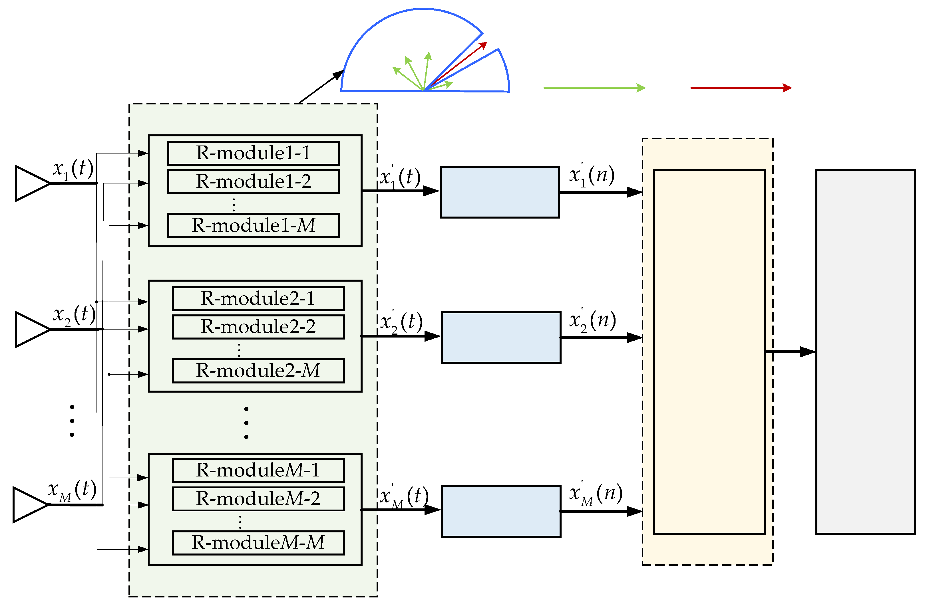
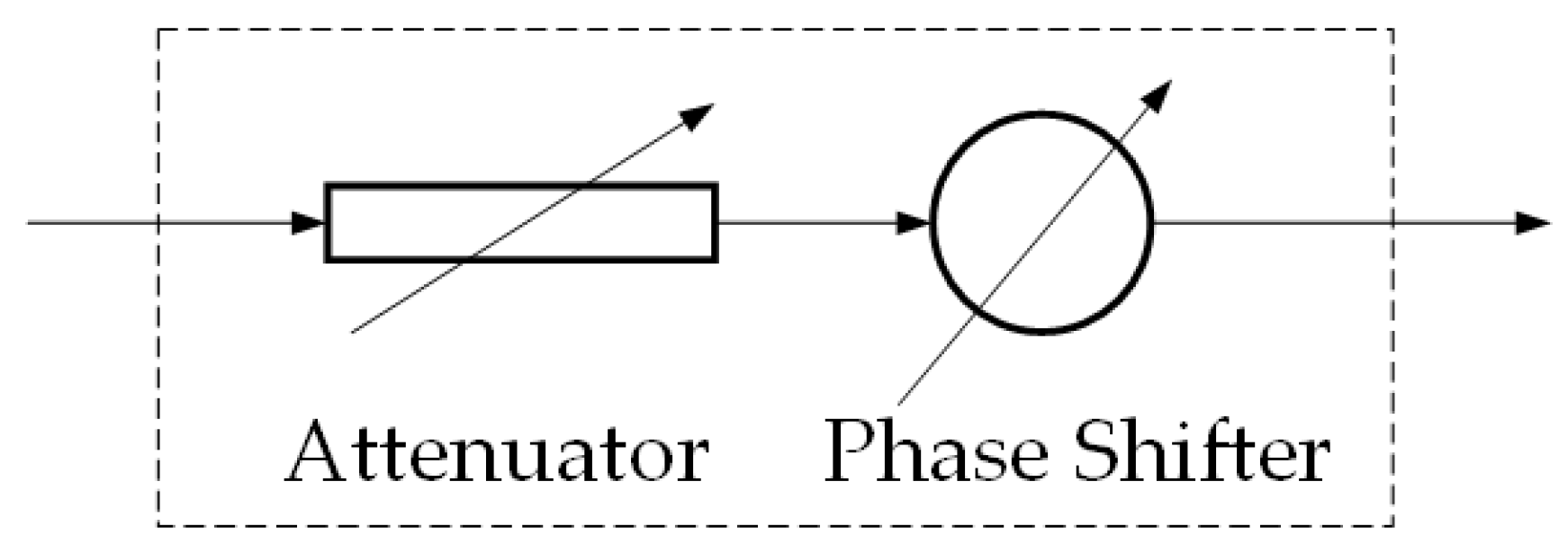
The proposed hybrid beamforming technique follows in this section. The hybrid array antenna receiver structure is shown in Figure 2.The receiver adopts a fully connected hybrid array structure containing multiple R-modules at the RFE. Each R-module contains an attenuator and a phase shifter, as shown in Figure 3.
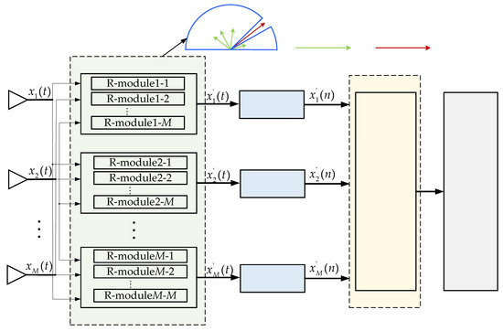
Figure 2.
The hybrid array receiver structure.

Figure 3.
The components meaning of the R-module.
Hybrid beamforming techniques include analog beamforming techniques and digital beamforming techniques, as shown in Figure 2.
(1) Analog beamforming technique. Taking the direction of arrival (DOA) of interference as a priori information, the multiple-notch filter (MNF) composed of M different 2D spatial-notch filters (SNF) is generated simultaneously in the baseband, as shown in Figure 2. The signal is filtered in the analog domain to partially suppress the strong interference and retain the original DOA distribution of the signal (including the GNSS signal and interference signal).
(2) Digital beamforming technique. After the data are filtered by the analog beamforming technique, they are sampled into the baseband through the RF channel and ADC. The original digital beamforming-based anti-jamming processing technique, that is, Equations (6) and (8), needs to be calibrated and then adopted to suppress interference in the digital domain. In the end, the final suppression of interference is completed.
In this paper, the analog beamforming weights are represented by h, and the digital beamforming weights are represented by w.
3.1. Analog Beamforming Technique
Firstly, the analog beamforming technique is introduced. As shown in Figure 2, the GNSS hybrid array receiver includes a total of M SNFs, represented by . Each SNF cannot be generated independently. The MNF not only needs to achieve partial suppression of interference in the analog domain but also strives to retain the original signal’s DOA information as much as possible. After GNSS and interference signals are filtered by the MNF, the signal can continue to retain the original DOA distribution in the baseband. Therefore, effective implementation of subsequent baseband anti-jamming algorithms can be ensured. The bampattern synthesis method is used to generate the MNF [20].
In the synthesis process of the MNF, different steering vector forms are used as follows:
Here, represents the steering vector corresponding to the m-th SNF; that is, the corresponding antenna is used as the reference antenna for each .
The SNF and MNF constraints are simultaneously applied to the synthesized pattern. The first SNF is generated by the SNF constraint. Then, using as a reference mask, the other notch filters are generated by the MNF constraints.
- (1)
- SNF Constraints
The SNF constraints include constraints on both non-interference and interference areas. The non-interference area and interference area are constrained separately. The 3 dB main lobe width of the interference spatial spectrum is used as a basis to distinguish between the non-interference area and the interference area. The area outside the 3 dB main lobe width of the interference spatial spectrum is the non-interference area, and the other area is the interference area.
The constraint for the non-interference area is as follows:
where the lower and upper magnitude bounds are applied [20]. In Equation (10), the non-interference area is divided into P uniformly spaced angles, represents the set of P angles in the non-interference area, i.e., , and is the ripple term.
The constraint for interference area is as
In Equation (11), Q represents the number of interferences, represents the set of Q angles for Q interference areas, i.e., , and is the nulling term.
As shown in Equations (10) and (11), P angles are used to constrain the non-interference area, but only one single angle is used to constrain each interference. This situation will lead to the inability of the objective function to converge and generate a deep enough null that meets the requirements. To solve this problem, the method of virtual interference is adopted, and the K interferences at the same interference direction are assumed. In practice, the value of K should be greater than or equal to the number of non-interference area constraint angles P, that is, K ≥ P. And then, Equation (11) is written as follows:
where
- (2)
- MNF Constraints
After the first SNF is generated based on the SNF constraints, the MNF constraints are used to generate . The MNF constraints are used to partially suppress the interference and retain the original DOA distribution of the signal. Omitting the noise term in Equation (1), the array input signal can be expressed as follows:
Here, represents the GNSS signal and interference signal. Substitute Equation (9) into Equation (14), the array input signal for each SNF in MNF can be represented as follows:
The output of the signal after being filtered by each SNF is
where . represents the beampattern of the m-th SNF. Therefore, the vector form of the output signal, after being filtered by the MNF, is
In the MNF beampattern synthesis, the below constraints are applied.
Then, Equation (17) can be written as follows:
Through Equation (19), it can be seen that the output data of the MNF can retain the original DOA distribution.
The Equation (18) for the MNF constraints can be written as follows:
Here, Equations (20) and (21) represent the consistency constraints for non-interference and interference areas between the m-th SNF and the first SNF, respectively. and represent the response error terms.
The norm of is adopted as the objective function, which is used to receive useful signals with high gain. The objective function is shown below.
Due to Equation (10), the objective function (22) is a nonconvex optimization problem, and the alternating directions method of multipliers (ADMM) optimization method is used to solve the objective function. It decomposes the problem into multiple sub-problems, iteratively solves the sub-problems in sequence, and obtains the final optimization result. The specific derivation process can be referred to in the literature [20,21]. The digital MNF is obtained through Equation (22), and it requires less than 100 iterations. After quantization, the analog beamforming coefficient is solved.
3.2. Digital Beamforming Technique
Secondly, a digital beamforming technique is introduced. The MVDR technique and PI technique in Equations (6) and (8) are still used in the digital beamforming part. However, through Equations (20) and (21), it can be seen that although we have retained the DOA distribution of the original GNSS signal as much as possible, a small amount of amplitude/phase error is inevitably introduced. Therefore, in order to maximize the interference suppression ability of the digital domain anti-jamming technique, two processes should be added: amplitude/phase error calculation and calibration.
The beampattern corresponding to each analog SNF should be firstly calculated as
Then, the calculation process of amplitude/phase error is as follows:
Here, represents the amplitude/phase error between the m-th SNF and the first SNF at angle .
Finally, the updated MVDR algorithm is obtained as follows:
where , , and represents the operation of transforming a vector into a diagonal matrix.
Due to the fact that a small amount of amplitude/phase error has no impact on the PI algorithm, Equation (8) is not updated in this section.
3.3. Implementation of Proposed Technique
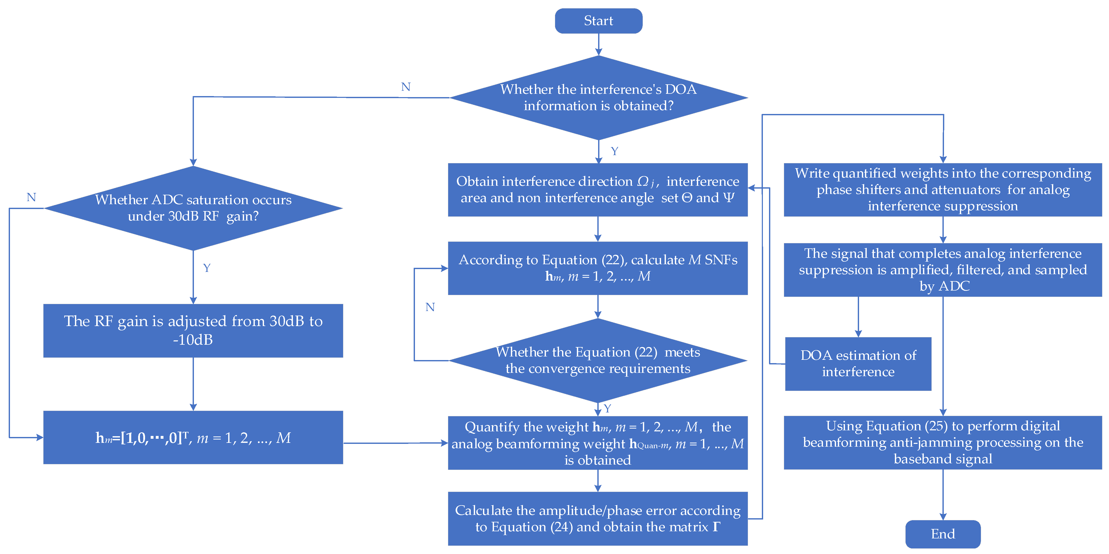
Figure 2 illustrates the data processing flowchart of the robust wideband interference suppression method for the GNSS array antenna receiver based on a hybrid beamforming technique. The steps of the method are as follows:
Step 1: Confirm whether the interference’s DOA information has been obtained. If the interference’s DOA information is obtained, move to Step 5. If not, move to Step 2.
Step 2: Confirm whether ADC saturation occurs. If ADC saturation occurs, move to Step 3. If not, move to Step 4.
Step 3: The RF gain is adjusted from 30 dB to −10 dB to ensure that ADC does not experience saturation. The interference DOA information of the first epoch can be obtained.
Step 4: Set the weight of the 2D spatial notch filter to , and then move to Step 7.
Step 5: Confirm whether the RF gain is set to 30 dB and set the RF gain to 30 dB. The prior information on interference direction is first obtained from DOA estimation, and then the interference angle set and the non-interference angle set are determined based on the interference direction.
Step 6: Based on sets and , analog beamforming technique in Section 3. 1 is run and M 2D spatial notch filters are obtained through multiple iterations.
Step 7: Quantify the weight ; the analog beamforming coefficient is obtained.
Step 8: Calculate the beampattern for each SNF based on Equation (23). And then calculate the amplitude/phase error matrix between each notch filter and the first SNF based on Equation (24).
Step 9: The analog MNF is written down to the corresponding phase shifters and attenuators in the hybrid array anti-jamming receiver.
Step 10: After filtering through the analog MNF, the signal is amplified, filtered, and sampled to the digital baseband signal .
Step 11: DOA estimation results can be obtained using a multiple signal classification (MUSIC) algorithm [22] on baseband data, and then DOA estimation results are sent to Step 5 in real-time.
Step 12: Using Equation (25), a digital beamforming technique is performed on the baseband data .
The robust wideband interference suppression process based on the hybrid beamforming technique is completed.
This section presents a hybrid beamforming-based GNSS anti-jamming method. Compared with the conventional digital beamforming-based anti-jamming method, there will be an obvious increase in hardware structure and implementation complexity. In terms of hardware structure, phase shifters and attenuations need to be added to the AFE, as shown in Figure 2. In terms of implementation, DOA estimation, analog MNF calculation, amplitude/phase error calculation, and calibration need to be added to the implementation, as shown in Figure 4.
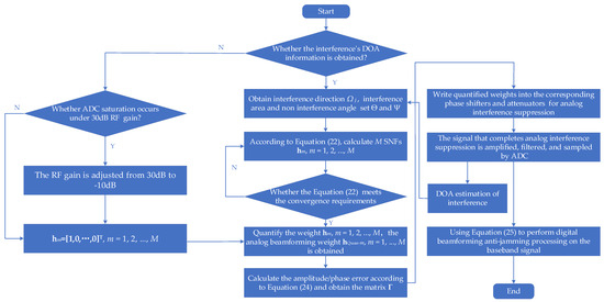
Figure 4.
The flowchart of the proposed method.
4. Simulations and Results
In this section, the performance of the proposed method in this paper is evaluated through simulations, which are performed using the MATLAB R2018b software platform. In Section 4.1, the simulation settings are presented. In Section 4.2, Simulation 1 verifies the analog beamforming performance of the proposed method in two types of interference scenarios. In Section 4.3, Simulation 2 verifies the strong interference suppression performance. In Section 4.4, Simulation 3 verifies the maximum interference suppression ability of the proposed method. In Simulations 2 and 3, the performance of the proposed method is compared with the digital beamforming-based anti-jamming technique. In order to fully verify the interference suppression ability of the proposed technique, the MVDR technique is used in hybrid beamforming-based and digital beamforming-based anti-jamming processing, respectively.
4.1. Simulation Settings
In the mathematical simulation verification, we use a 7-element array antenna, as shown in Figure 1. The GNSS receiver simulation parameters are shown in Table 1. The interference distribution is shown in Table 2. The simulation includes six interference scenarios. Scenarios 1–3 are the single-interference scenarios, and Scenarios 4–6 are the two-interference scenarios. The GNSS constellation adopts the real constellation, as shown in Table 3. The parameter settings of the analog beamforming technique in Section 3.1 are shown in Table 4.

Table 1.
Parameters of the GNSS receiver.
Table 2.
The interference distribution.
Table 3.
The GNSS constellation distribution.
Table 4.
Parameters of the analog beamforming.
4.2. Simulation 1: Analog Beamforming Performance Verification
The analog beamforming technique is the key part of the proposed method. In this section, the performance of the analog MNF is verified, including the performance verification of each SNF and the consistency analysis between each SNF in the MNF. The performance of each SNF is calculated by Equation (23). The gain G in the non-interference area and the nulling depth D in the interference area are calculated. The calculation formulas of the amplitude error and phase error between each SNF and the first SNF in the non-interference area are as follows:
where represents the absolute value operation and represents the operation of taking complex phase.
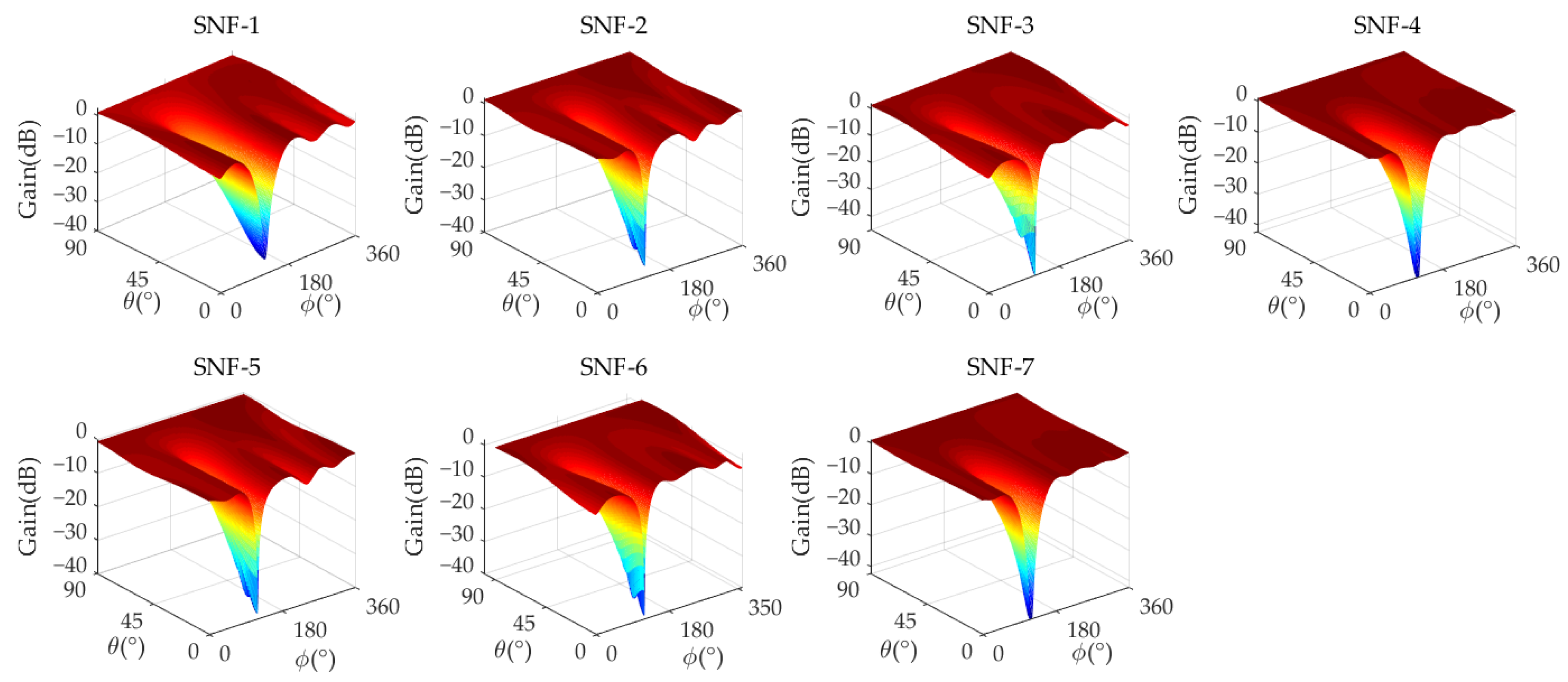
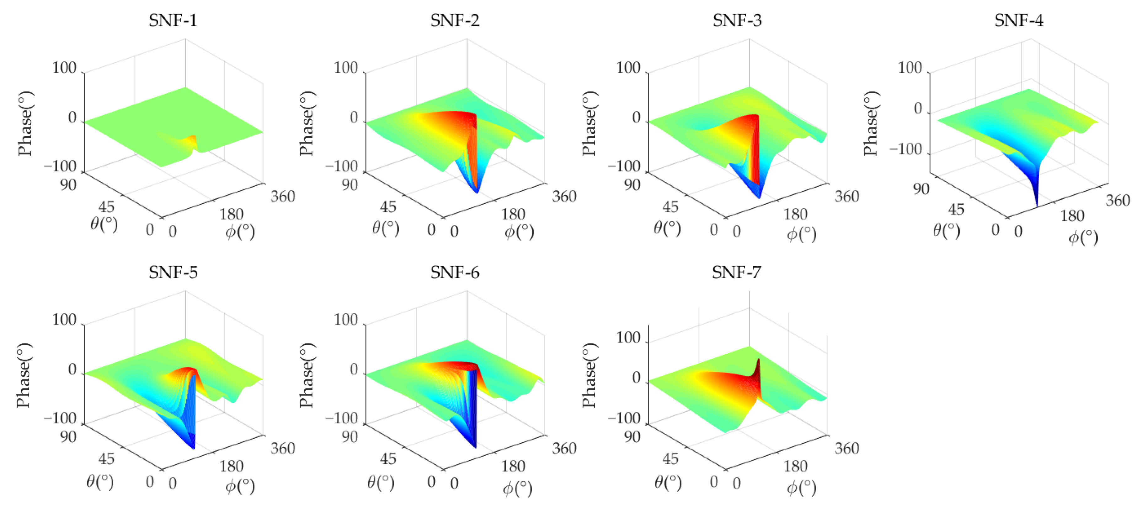
Figure 5 and Figure 6 show the amplitude/phase response of the analog MNF. The performance of analog MNF is calculated, where , , , , , and represent the maximum gain, minimum gain, average amplitude error, maximum amplitude error, average phase error, and maximum phase error in the non-interference area, respectively, and D represents the nulling depth in the interference direction. The detailed performance results are shown in Table 5.

Figure 5.
The analog MNF amplitude response of a 7-element antenna (Scenario 1).
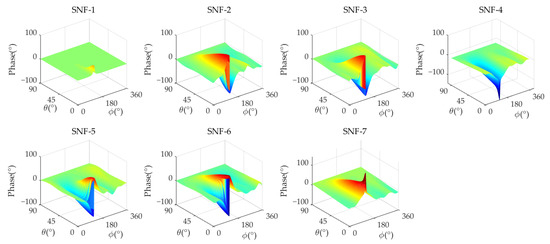
Figure 6.
The analog MNF phase response of a 7-element antenna (Scenario 1).
Table 5.
Performance statistics of analog MNF * (Scenario 1).
From Table 5, it can be seen that in the analog MNF, the maximum gain of all SNFs is 2.687 dB, the minimum gain is −4.683 dB, and the minimum nulling depth of each SNF in the analog MNF D is −35.07 dB. The amplitude/phase error between each SNF and reference SNF-1 in the analog MNF is that the maximum average amplitude error is 1.812 dB, the maximum amplitude error is 4.508 dB, the maximum average phase error is 3.96°, and the maximum phase error is 17.47°. This amplitude/phase error could meet the requirements of the array antenna.
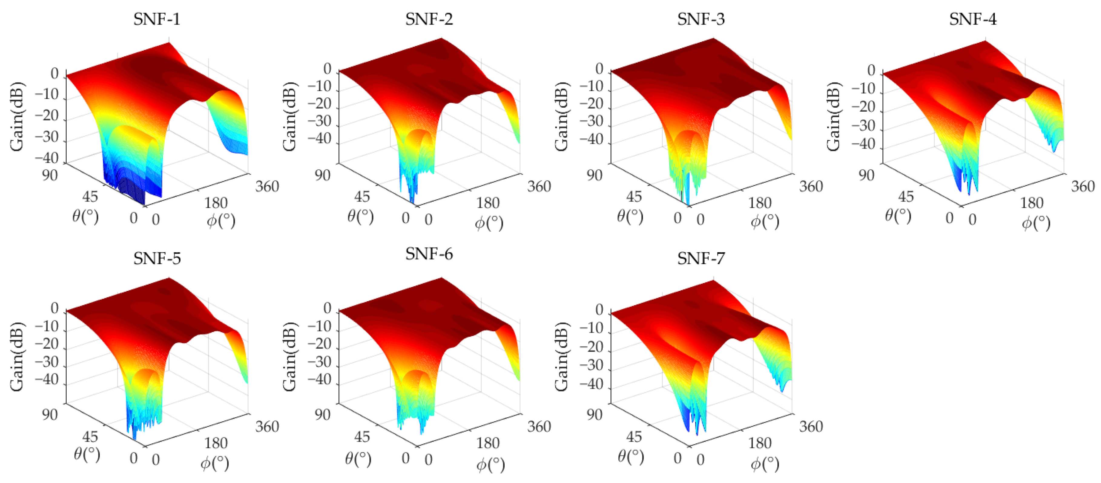
Figure 7 and Figure 8 show the amplitude/phase response of the analog MNF in Scenario 4, and Table 6 presents the detailed performance of the analog MNF. In this scenario, the minimum nulling depth of each SNF in the analog MNF D is −34.22 dB, the maximum gain is 1.646 dB, the minimum gain is 0.687 dB, the maximum average amplitude error is 1.016 dB, the maximum amplitude error is 4.459 dB, the maximum average phase error is 3.451°, and the maximum phase error is 18.49°.
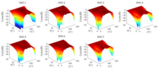
Figure 7.
The analog MNF amplitude response of a 7-element antenna (Scenario 4).
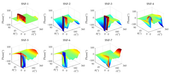
Figure 8.
The analog MNF phase response of a 7-element antenna (Scenario 4).
Table 6.
Performance statistics of analog MNF * (Scenario 4).
4.3. Simulation 2: Strong Interference Suppression Performance Verification
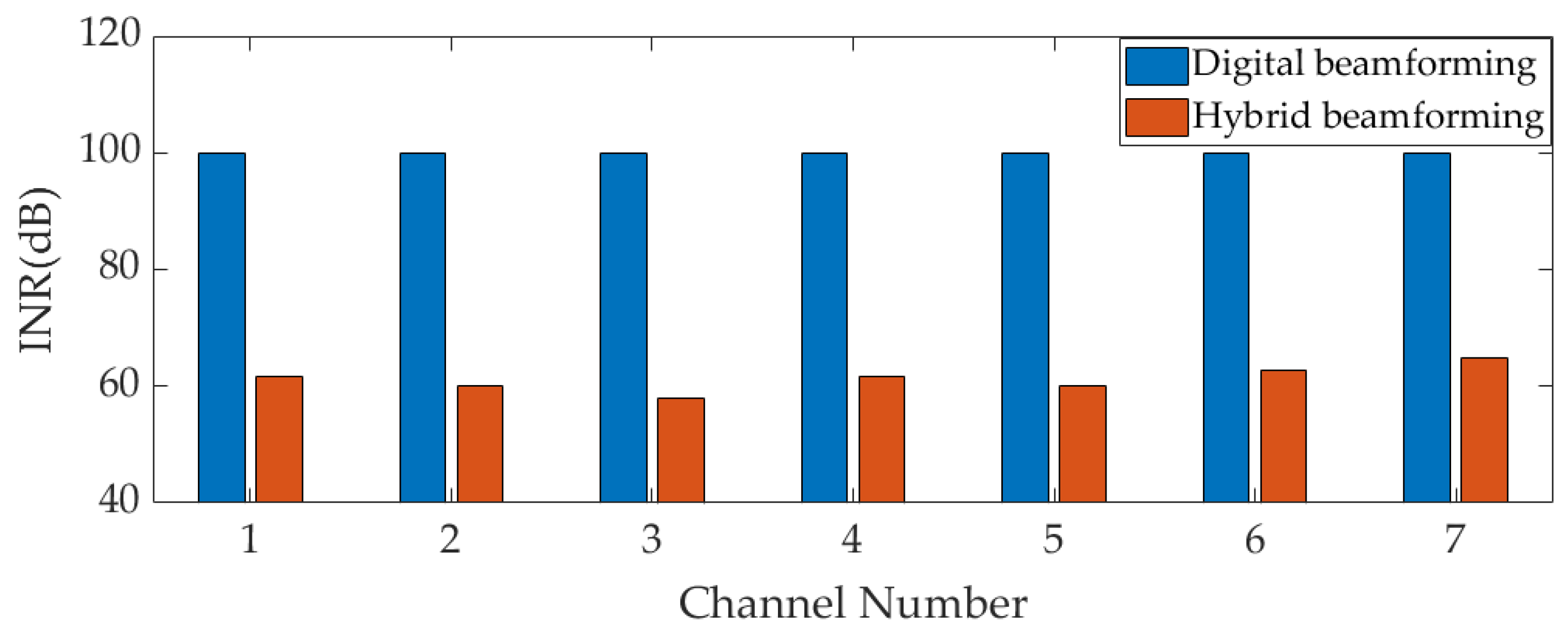
In this section, the strong interference suppression performance of the proposed method is verified and compared with the digital beamforming-based technique. The interference power is set to 0 dBm; that is, the input interference-to-noise ratio (INR) is 100 dB.
Firstly, the interference suppression ability of the analog MNF in the analog domain is verified. The nulling depth values for two scenarios (Scenarios 1 and 4) can be seen in Table 5 and Table 6, but they do not accurately reflect the interference suppression ability of the MNF. The interference suppression ability of the MNF is accurately demonstrated by comparing the input INR and INR before ADC sampling in the receiver. The INR of the two scenarios after their respective MNFs is shown in Figure 9 and Figure 10. In the figures, red represents the INR after the analog MNF, the blue color indicates the input INR, and both are also the INR before ADC sampling in two array forms. In Figure 9, it can be seen that after the interference is filtered by the analog MNF, the input INR of the hybrid array decays from 100 dB to 61.6 dB, 59.95 dB, 58.06 dB, 61.77 dB, 59.98 dB, 62.82 dB, and 64.8 dB, respectively. The wideband interference suppression ability of each SNF is 38.4 dB, 40.05 dB, 41.94 dB, 38.23 dB, 40.02 dB, 37.18 dB, and 35.2 dB, respectively. In Scenario 4, after two interferences enter the channel, the interference’s power should be the sum of the two interferences, so the input INR increases to 106 dB. In Figure 10, the input INR of the hybrid array decays from 106 dB to 64.91 dB, 60.5 dB, 60.49 dB, 67.1 dB, 63.31 dB, 64.61 dB, and 67.03 dB, respectively. The wideband interference suppression ability of each SNF is 41.09 dB, 45.95 dB, 45.51 dB, 38.9 dB, 42.69 dB, 41.39 dB, and 38.97 dB, respectively. The interference suppression ability of Scenario 4 is achieved through the combination of two nulls. From Figure 9 and Figure 10, it can be seen that, due to the partial suppression of interference in the analog domain, the technique proposed in this paper can effectively relax the linear dynamic range of AFE to prevent saturation in strong interference scenarios. However, due to the presence of strong wideband interference, digital beamforming-based anti-jamming array antenna receivers will experience AFE saturation, which results in signal distortion and the inability to operate baseband processing. After the interference suppression ability of the analog MNF is verified, the interference suppression ability of a hybrid beamforming-based array antenna receiver in strong interference scenarios will be verified.
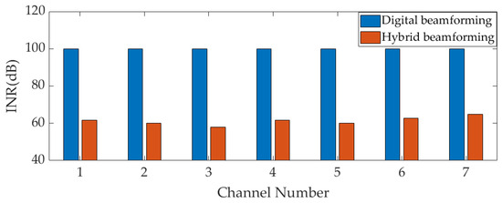
Figure 9.
The INR of each RF channel before ADC sampling (Scenario 1).
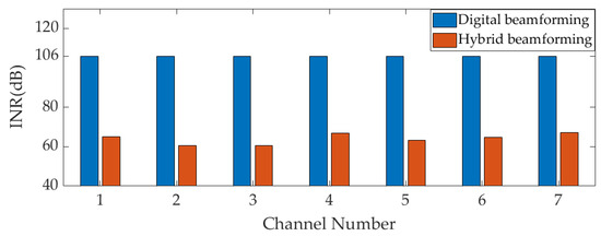
Figure 10.
The INR of each RF channel before ADC sampling (Scenario 4).
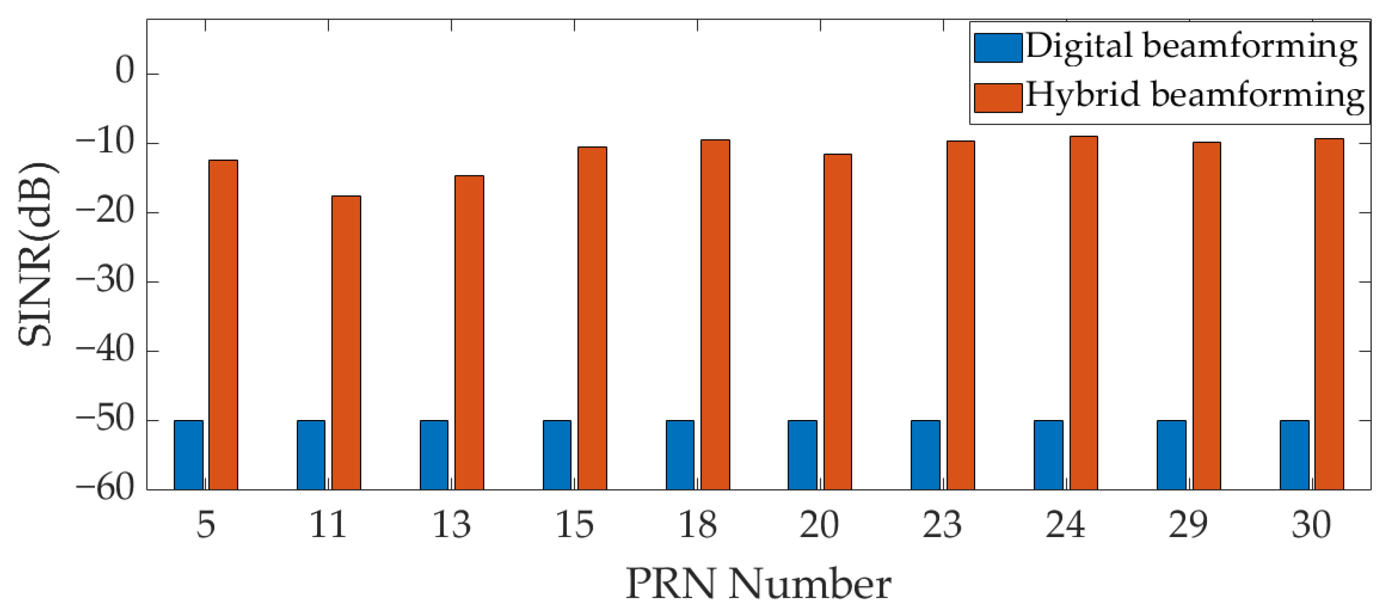
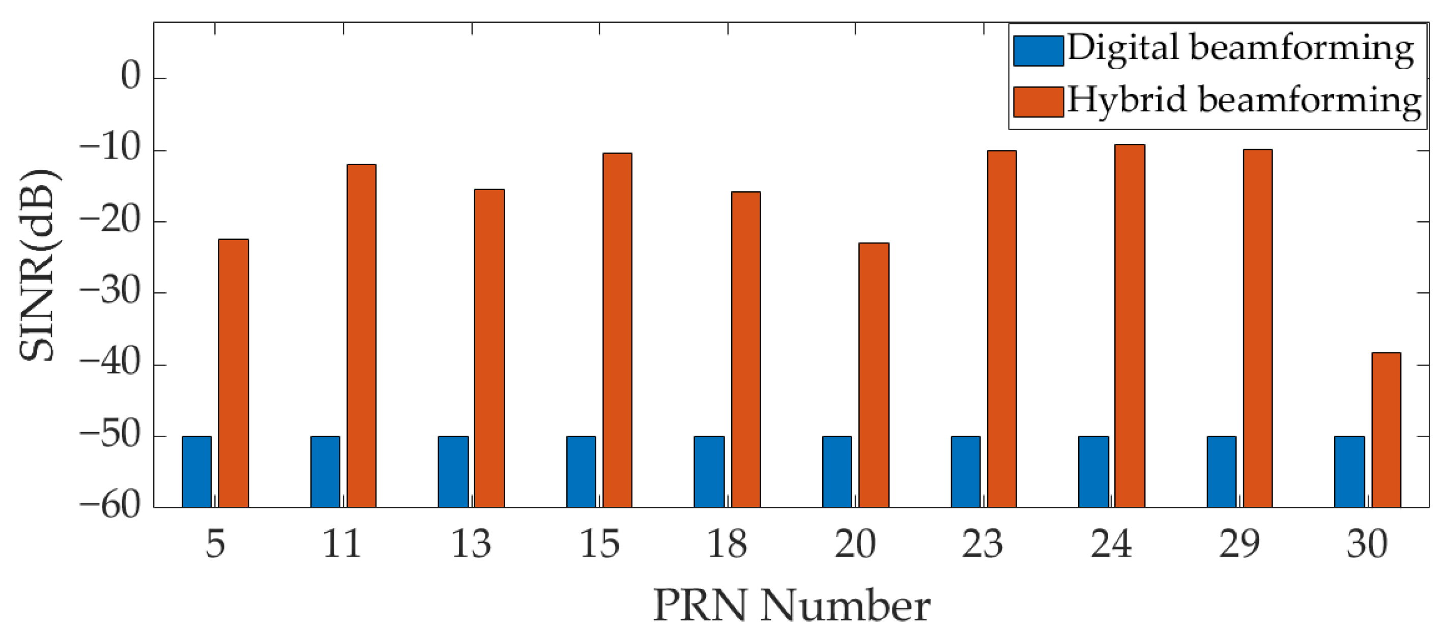
The interference suppression ability of a hybrid beamforming-based array antenna receiver is verified by comparing the output signal-to-interference-noise ratio (SINR) of the two array forms under strong interference conditions. Due to AFE saturation, the sampled signal is distorted, and the digital beamforming in two array forms is ineffective. Therefore, the statistics of SINR after AFE saturation are no longer meaningful. The SINR is uniformly set to −50 dB when AFE experiences saturation.
Figure 11 and Figure 12, respectively, show the output SINR of the two scenarios (Scenarios 1 and 4) in Table 2 under input INR = 100 dB. Due to AFE saturation in the digital array at this INR, the output SINR of all GNSS signals is −50 dB. However, in the hybrid array, due to the partial suppression of interference by analog MNF in the analog domain, the AFE does not experience saturation, and the digital beamforming of the hybrid array can work normally. The output SINR of each GNSS signal is calculated after digital beamforming in the hybrid array. As shown in Figure 11, the output SINR of GNSS signal in Scenario 1 are −12.33 dB, −17.49 dB, −14.69 dB, −10.43 dB, −9.49 dB, −11.46 dB, −9.56 dB, −9.01 dB, −9.78 dB, and −9.33 dB, respectively; As shown in Figure 12, the output SINR of GNSS signal in Scenario 4 are −22.39 dB, −11.96 dB, −15.41 dB, −10.32 dB, −15.87 dB, −22.92 dB, −10.02 dB, −9.21 dB, −9.85 dB, and −38.22 dB, respectively. In the two scenarios, after the signal is processed by the hybrid beamforming technique, the number of GNSS signals with an output SINR greater than −25 dB is 10 and 9, respectively, which can be captured. The hybrid beamforming-based array antenna receiver can effectively complete the GNSS PVT solution under input INR = 100 dB. However, due to AFE saturation, the digital beamforming-based array antenna receiver cannot work normally.

Figure 11.
The output SINR under INR = 100 dB (Scenario 1).
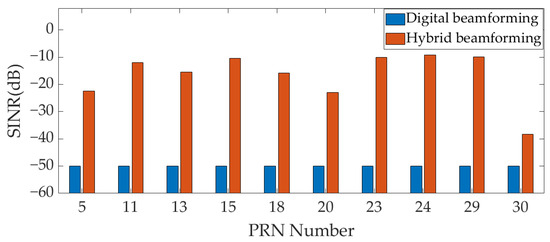
Figure 12.
The output SINR under INR = 100 dB (Scenario 4).
4.4. Simulation 3: Maximum Interference Suppression Ability Performance Verification
In this section, the maximum interference suppression ability of the proposed method is verified and compared with the beamforming-based technique.
To verify the improvement of the proposed technique in its maximum interference suppression ability, the output SINR of all GNSS signals in Table 2 is calculated under different input INR conditions in six scenarios. The interference power is from −40 dBm to 30 dBm, and the step length of the interference power is 2 dBm; that is, the INR is from 60 dB to 130 dB.
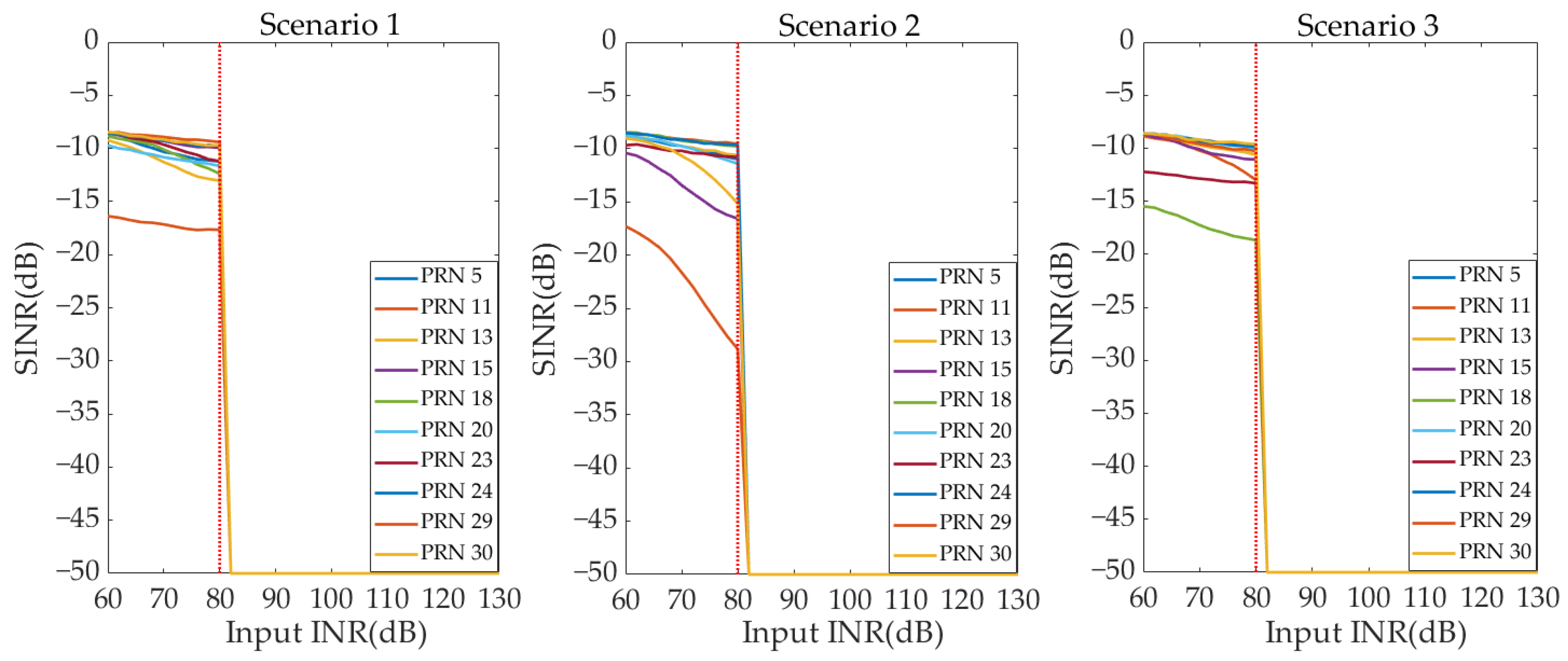
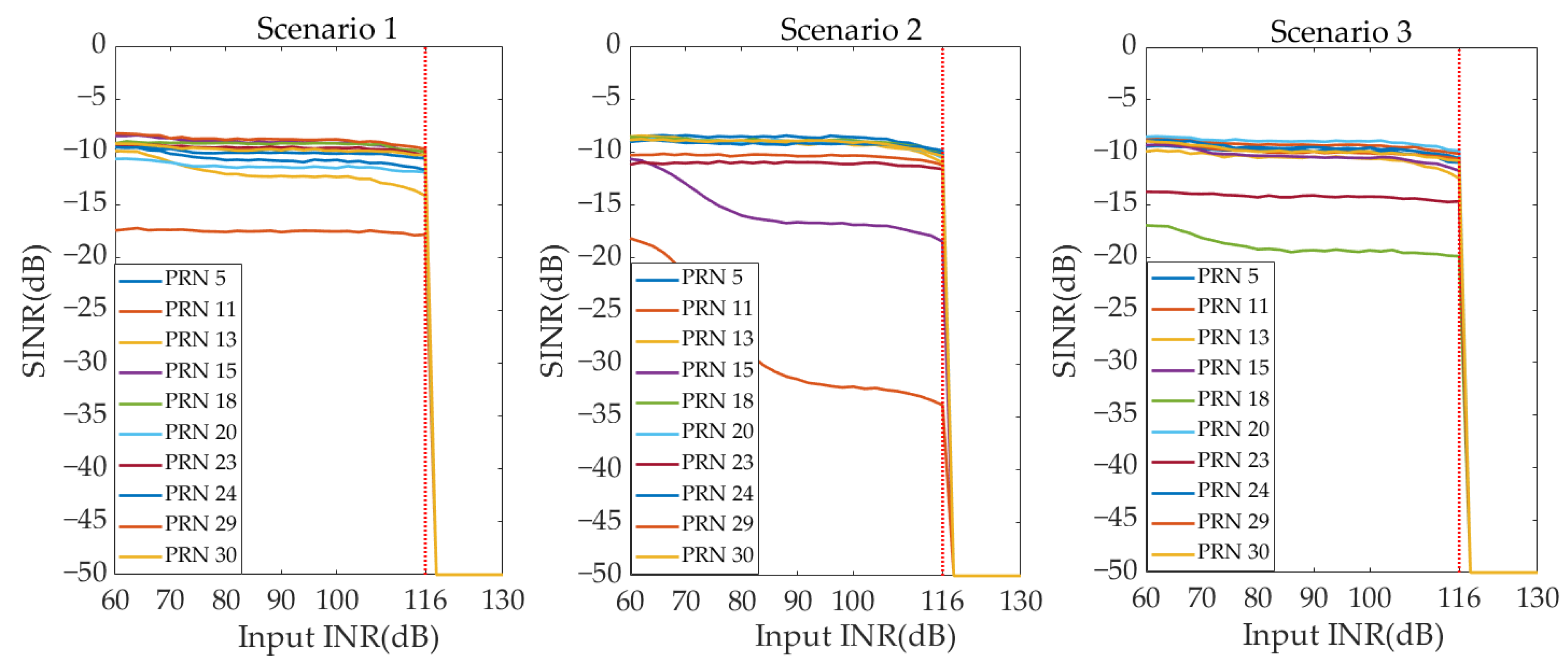
Figure 13 and Figure 14, respectively, show the output SINR curves of all GNSS signals under different INR conditions for the two beamforming techniques in Scenarios 1–3. From Figure 13, it can be seen that when the input INR is ≤ 80 dB, the digital beamforming-based array antenna receiver can complete anti-jamming processing normally. The number of satellites that can be captured in three scenarios is 10, 9, and 10, respectively. And the output SINR of the captured satellites is greater than −25 dB. Therefore, the GNSS PVT solution can be completed. When the input INR is greater than 80 dB, the digital beamforming-based array antenna receiver experiences AFE saturation. All GNSS signals’ output SINRs are −50 dB, and the number of available satellites is 0. The receiver is unable to complete the GNSS PVT solution. Therefore, the maximum interference suppression ability of the digital beamforming-based array antenna receiver is INR = 80 dB. From Figure 14, it can be seen that the AFE saturation of the hybrid beamforming-based array antenna receiver occurs when the input INR > 116 dB. When the input INR is ≤ 116 dB, the number of satellites that can be captured in three scenarios is 10, 9, and 10, respectively. Moreover, the output SINR of the captured satellites is greater than −25 dB. The receiver can complete the GNSS PVT solution normally. Therefore, the maximum interference suppression ability of a hybrid beamforming-based array antenna receiver is INR = 116 dB. Therefore, in Scenarios 1–3, compared with the digital beamforming-based array antenna receiver, the maximum interference suppression ability of the hybrid beamforming-based anti-jamming receiver is improved by 36 dB.

Figure 13.
The SINR curve under different INR—digital beamforming (Scenarios 1–3).
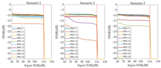
Figure 14.
The SINR curve under different INR—hybrid beamforming (Scenarios 1–3).
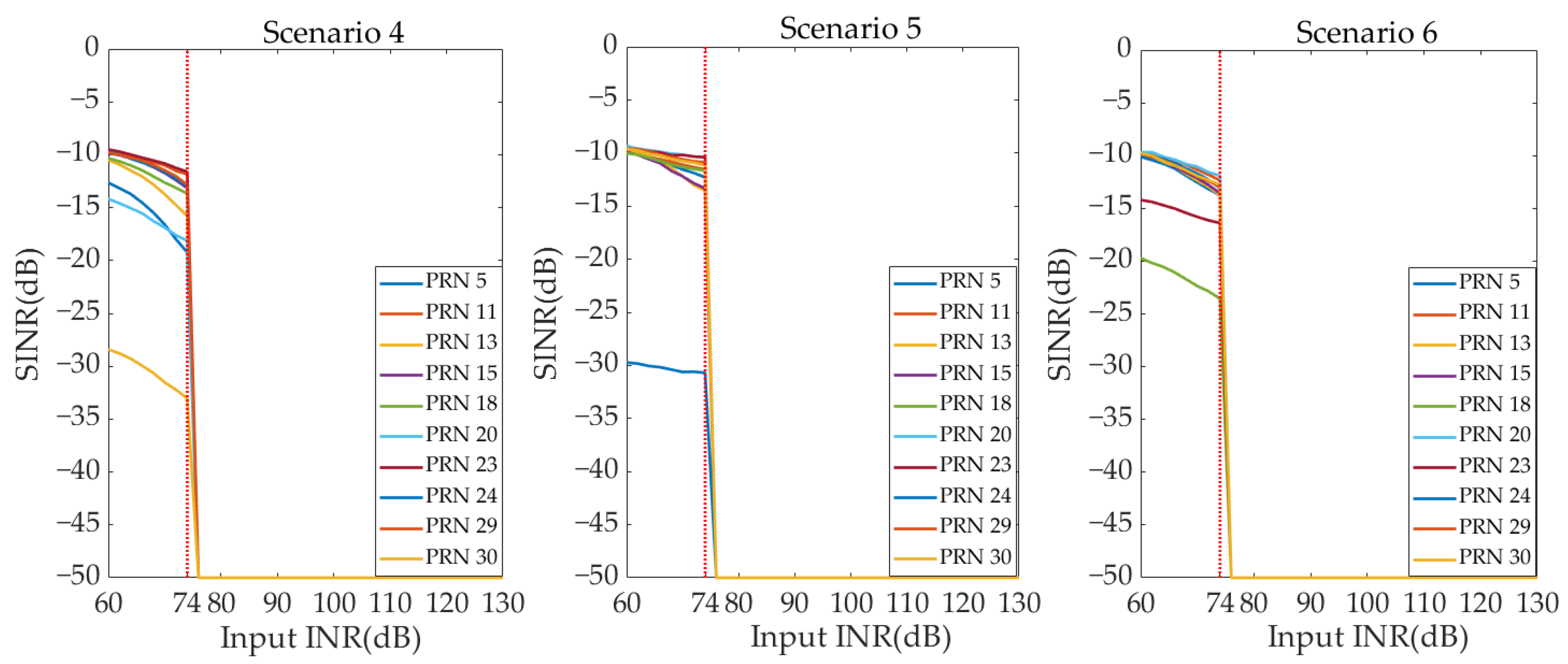
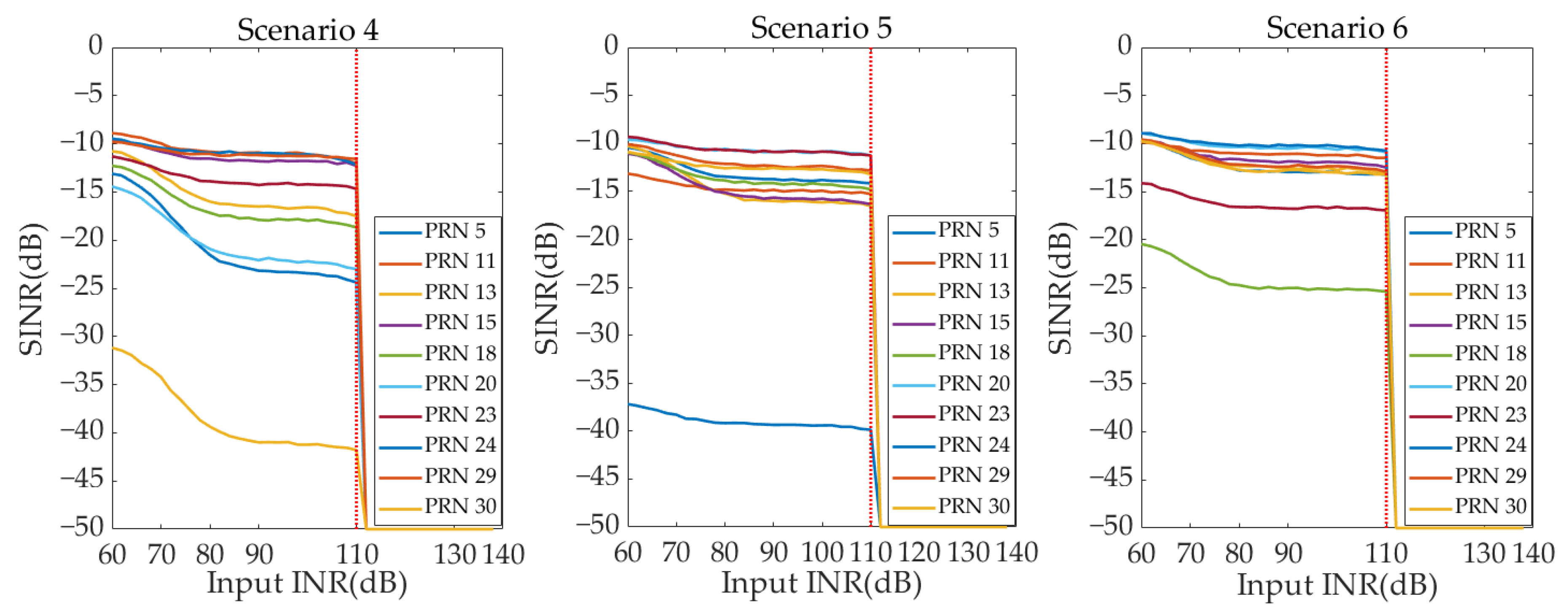
Figure 15 and Figure 16, respectively, show the output SINR curves of all GNSS signals under different INR conditions of the two beamforming techniques in Scenarios 4–6. The AFE saturation position of the digital beamforming-based array antenna receiver is input INR = 74 dB. However, the AFE saturation position of the hybrid beamforming-based array antenna receiver is input INR = 110 dB. Therefore, in Scenarios 4–6, compared with the digital beamforming-based array antenna receiver, the maximum interference suppression ability of the hybrid beamforming-based array antenna receiver is also improved by 36 dB. In Figure 13, Figure 14, Figure 15 and Figure 16, the output SINR of GNSS satellites close to the interference decreases rapidly as the interference power increases in six scenarios.
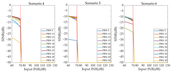
Figure 15.
The SINR curve under different INR—digital beamforming (Scenarios 4–6).
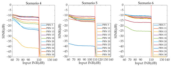
Figure 16.
The SINR curve under different INR—hybrid beamforming (Scenarios 4–6).
5. Discussion
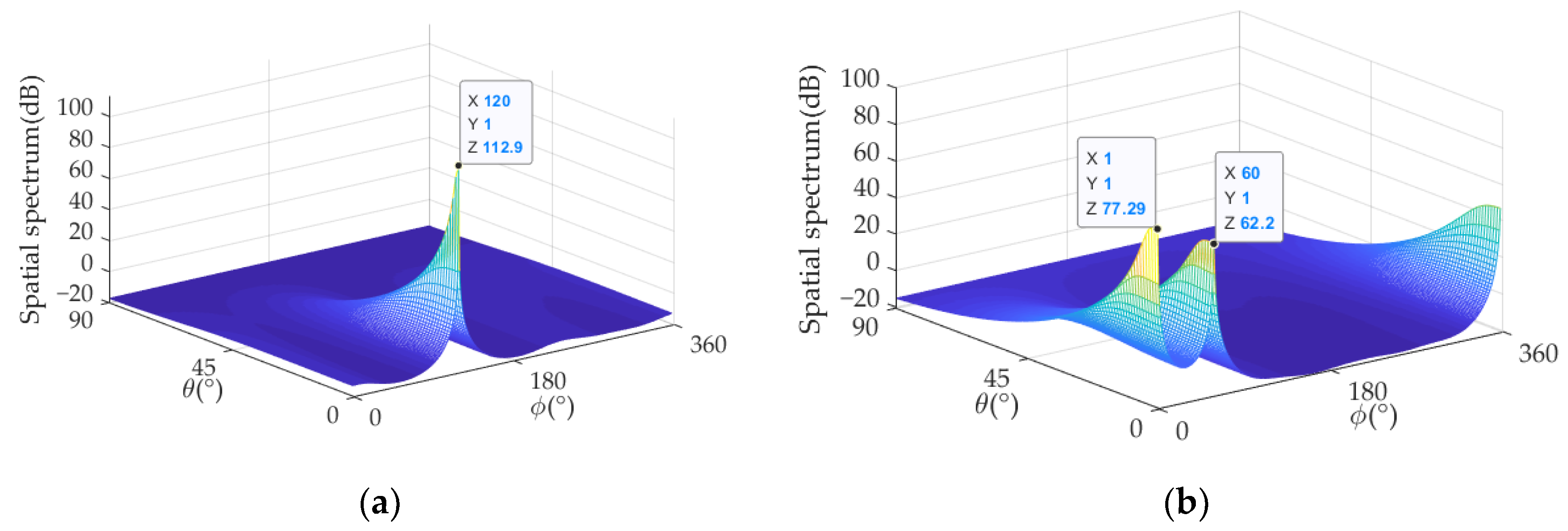
In the present study, the method proposed in this paper takes the interference’s DOA as the prior information, and it requires continuous tracking of the interference direction from the weak interference scenario to the strong interference scenario. Figure 17 shows the DOA estimation results for two interference scenarios (Scenarios 1 and 4) with INR = 100 dB. It can be seen that the interference after analog MNF still retains the original DOA distribution. The performance in retaining the DOA distribution of signals in the proposed technique is also verified.

Figure 17.
DOA estimation results under hybrid beamforming (INR = 100 dB). (a) DOA estimation result in Scenario 1. (b) DOA estimation result in Scenario 4.
6. Conclusions
Aiming at the AFE saturation problem caused by the strong wideband interference in GNSS array antenna receivers. The hybrid beamforming-based anti-jamming technique is proposed. The main contributions are as follows:
- (1)
- A novel, fully connected hybrid array anti-jamming receiver structure is proposed. It is used for hybrid beamforming by adding the attenuators and phase shifters to the AFE.
- (2)
- A hybrid beamforming method for the GNSS array antenna receiver is proposed. In the analog domain, the interference is partially suppressed (better than 30 dB) by analog MNF generated in the baseband, and it relaxes the linear dynamic range of AFE to prevent saturation under the strong interference scenario. In the digital domain, the calibrated MVDR algorithm is used for the final suppression of residual interference.
- (3)
- Through six interference scenarios, compared with the digital beamforming-based array antenna receiver, it is verified that the maximum interference suppression ability of the hybrid beamforming-based array antenna receiver is improved by 36 dB under the conditions of using 7-bit attenuators and 8-bit phase shifters.
There are several issues that should be considered in future work: (1) Space-time hybrid array structures should be considered. Firstly, it can provide higher interference suppression ability in the analog domain. Secondly, it can increase the degree of freedom to ensure that the signal has better amplitude consistency, especially phase consistency, after it is filtered by the analog MNF. (2) The algorithm in this paper assumes that the array antenna is ideal and ignores the influence of amplitude/phase error in practical applications. In analog beamforming, the influence of non-ideal factors will be further considered, and the analog beamforming algorithm will be modified accordingly. (3) This article only verifies the improvement of anti-jamming ability under static conditions. The anti-jamming performance under dynamic conditions needs to be verified through field experiments, and further consideration needs to be given to the width parameter setting of nulling in analog beamforming.
Author Contributions
Conceptualization, Z.X. (Zhenxing Xu) and Q.D.; data curation, M.W. and H.W.; formal analysis, Z.X. (Zhenxing Xu); funding acquisition, M.W. and F.Y.; investigation, G.Z. and H.W.; methodology, Z.X. (Zhenxing Xu) and M.W.; project administration, S.L. and F.Y.; software, Z.X. (Zhenxing Xu) and M.W.; supervision, Q.D. and S.L.; validation, Z.X. (Zhenxing Xu) and G.Z.; visualization, S.Z.; writing—original draft preparation, Z.X. (Zhenxing Xu); writing—review and editing, Z.X. (Zhenghuan Xia), X.C. and M.W. All authors have read and agreed to the published version of the manuscript.
Funding
This research was funded by the National Key Research and Development Program of China (Grant No. 2023YFB3906500).
Data Availability Statement
Dataset available on request from the authors.
Conflicts of Interest
The authors declare no conflicts of interest.
References
- Chien, Y.R. Design of GPS Anti-Jamming Systems Using Adaptive Notch Filters. IEEE Syst. J. 2015, 9, 451–460. [Google Scholar] [CrossRef]
- Ni, G.; He, C.; Jin, R. Single-Channel Anti-Jamming Receiver With Harmonic-Based Space-Time Adaptive Processing. IEEE Wirel. Commun. Lett. 2022, 11, 776–780. [Google Scholar] [CrossRef]
- Gioia, C.; Borio, D. Multi-layered Multi-Constellation Global Navigation Satellite System Interference Mitigation. Navigation 2023, 70, 596. [Google Scholar] [CrossRef]
- Borio, D.; Gioia, C. GNSS interference mitigation: A measurement and position domain assessment. Navigation 2021, 68, 93–114. [Google Scholar] [CrossRef]
- Kraus, T.; Pany, T.; Eissfeller, B. Maximum Theoretical Interference Mitigation Capability of a GNSS Receiver as Limited by the GNSS Frontend. In Proceedings of the 30th International Technical Meeting of the Satellite Division of The Institute of Navigation (ION GNSS+ 2017), Portland, Oregon, 25–29 September 2017; pp. 3471–3480. [Google Scholar]
- Borio, D.; Gioia, C. Interference mitigation: Impact on GNSS timing. GPS Solut. 2021, 25, 37. [Google Scholar] [CrossRef]
- Borio, D.; Li, H.; Closas, P. Huber’s Non-Linearity for GNSS Interference Mitigation †. Sensors 2018, 18, 2217. [Google Scholar] [CrossRef] [PubMed]
- Dovis, F. GNSS Interference Threats and Countermeasures; Artech House: Boston, MA, USA, 2015; pp. 62–64. [Google Scholar]
- Betz, J.W. Engineering Satellite-Based Navigation and Timing: Global Navigation Satellite Systems, Signals, and Receivers; Wiley: New York, NY, USA, 2016; pp. 39–42. [Google Scholar]
- Li, Y.; Cervantes, J.; Shivaramaiah, N.C.; Akos, D.M.; Wang, M. Configurable GPS/GNSS Antenna Module Resistant to RFI Saturation. IEEE Trans. Aerosp. Eletron. 2020, 56, 381–392. [Google Scholar] [CrossRef]
- Huo, S.; Nie, J.; Tang, X.; Wang, F. Minimum Energy Block Technique Against Pulsed and Narrowband Mixed Interferers for Single Antenna GNSS Receivers. IEEE Commun. Lett. 2015, 19, 1933–1936. [Google Scholar] [CrossRef]
- Wu, K.; Zhang, J.A.; Huang, X.; Guo, Y.J.; Nguyen, D.N.; Kekirigoda, A.; Hui, K.P. Analog-Domain Suppression of Strong Interference Using Hybrid Antenna Array. Sensors 2022, 22, 2417. [Google Scholar] [CrossRef] [PubMed]
- Krishnaswamy, H.; Zhang, L. Analog and RF Interference Mitigation for Integrated MIMO Receiver Arrays. Proc IEEE 2016, 104, 561–575. [Google Scholar] [CrossRef]
- Golabighezelahmad, S.; Klumperink, E.A.M.; Nauta, B. A 0.7–5.7 GHz Reconfigurable MIMO Receiver Architecture for Analog Spatial Notch Filtering Using Orthogonal Beamforming. IEEE J. Solid-State Circuits 2021, 56, 1527–1540. [Google Scholar] [CrossRef]
- Lin, T.; Wei, X.; Lai, J.; Xie, M. Transmit Beamforming Design Based on Multi-Receiver Power Suppression for STAR Digital Array. Sensors 2024, 24, 622. [Google Scholar] [CrossRef] [PubMed]
- Wang, G.; Yang, Z.; Gong, T. Hybrid Beamforming Design for Self-Interference Cancellation in Full-Duplex Millimeter-Wave MIMO Systems with Dynamic Subarrays. Entropy 2022, 24, 1687. [Google Scholar] [CrossRef] [PubMed]
- Sun, Y.; Chen, F.; Lu, Z.; Wang, F. Anti-Jamming Method and Implementation for GNSS Receiver Based on Array Antenna Rotation. Remote Sens. 2022, 14, 4774. [Google Scholar] [CrossRef]
- Li, S.; Wang, F.; Tang, X.; Ni, S.; Lin, H. Anti-Jamming GNSS Antenna Array Receiver with Reduced Phase Distortions Using a Robust Phase Compensation Technique. Remote Sens. 2023, 15, 4344. [Google Scholar] [CrossRef]
- Li, S.; Lin, H.; Tang, X.; Ma, C.; Wang, F. Noncoherent Channel Combining for GNSS Signal Tracking with an Adaptive Antenna Array. Remote Sens. 2024, 16, 213. [Google Scholar] [CrossRef]
- Liang, J.; Zhang, X.; So, H.C.; Zhou, D. Sparse Array Beampattern Synthesis via Alternating Direction Method of Multipliers. IEEE Trans. Antennas Propag. 2018, 66, 2333–2345. [Google Scholar] [CrossRef]
- Liang, J.; Fan, X.; Fan, W.; Zhou, D.; Li, J. Phase-Only Pattern Synthesis for Linear Antenna Arrays. IEEE Antennas Wirel. Propag. Lett. 2017, 16, 3232–3235. [Google Scholar] [CrossRef]
- Mills, K.; Ahmad, F.; Amin, M.G.; Himed, B. Fast Iterative Interpolated Beamforming for Interference DOA Estimation in GNSS Receivers Using Fully Augmentable Arrays. In Proceedings of the 2019 IEEE Radar Conference (Radar Conf), Boston, MA, USA, 22–26 April 2019. [Google Scholar]


Disclaimer/Publisher’s Note: The statements, opinions and data contained in all publications are solely those of the individual author(s) and contributor(s) and not of MDPI and/or the editor(s). MDPI and/or the editor(s) disclaim responsibility for any injury to people or property resulting from any ideas, methods, instructions or products referred to in the content. |
© 2024 by the authors. Licensee MDPI, Basel, Switzerland. This article is an open access article distributed under the terms and conditions of the Creative Commons Attribution (CC BY) license (https://creativecommons.org/licenses/by/4.0/).