Article

Spaceborne HRWS-SAR-GMTI System Design Method with Optimal Configuration

1
School of Electronic Information and Electrical Engineering, Shanghai Jiao Tong University, Shanghai 200240, China
2
Shanghai Academy of Spaceflight Technology, Shanghai 201109, China
3
College of Information, Mechanical and Electrical Engineering, Shanghai Normal University, Shanghai 201418, China
4
Shanghai Institute of Satellite Engineering, Shanghai 201100, China
*
Author to whom correspondence should be addressed.
Remote Sens. 2024, 16(12), 2148; https://doi.org/10.3390/rs16122148
Submission received: 25 April 2024 / Revised: 30 May 2024 / Accepted: 7 June 2024 / Published: 13 June 2024

Abstract

:
The spaceborne high-resolution and wide-swath synthetic aperture radar (HRWS-SAR) system combined with the ground moving target indication (GMTI) mode provides a promising prospect in the realization of wide-area target surveying and high-resolution target imaging. In this paper, a system design method is proposed for an HRWS-SAR-GMTI system with ideal reconstruction configuration. In the proposed method, the whole azimuth receiving channels are uniformly divided into multiple groups, where HRWS-SAR imaging is implemented in each sub-group and then GMTI processing is performed based on the reconstructed SAR images. Then, an optimal candidate PRF is properly selected with respect to the optimal reconstruction configuration. After that, the digital beam forming scanning on receive (DBF-SCORE) technique is applied to further enlarge the range swath and improve the noise equivalent scattering coefficient (NESZ). Based on the predesigned system, HRWS-SAR image-based GMTI processing can finally be accomplished. The effectiveness of the proposed method is validated by simulated experiments.

1. Introduction

As an advanced technology used for remote sensing, spaceborne synthetic aperture radar (SAR) can achieve all-weather and all-day earth monitoring and obtain high-resolution images of areas of interest. Combined with the ground moving target indication (GMTI) mode, the spaceborne SAR system can effectively separate the moving targets from ground static scenes, which is widely used in many fields, such as reconnaissance of battlefield targets, sea surface monitoring, and traffic information collection [1].
In recent years, multichannel SAR-GMTI technology has experienced rapid development. LEE et al. applied the multichannel along-track interferometric (ATI)-based GMTI technique in an SAR system, which can effectively realize moving target detection and velocity estimation by using TerraSAR-X data [2,3]. Zheng et al. adopted the displaced phase center antenna (DPCA) to realize the main-lobe clutter rejection in an SAR-GMTI system, which can effectively accomplish moving target detection when the optimal observation configuration is applied after performing precise SAR image-domain registration error and channel phase/amplitude error compensation [4,5]. In [6], BRENNAN et al. presented the theory of space–time adaptive processing (STAP), which can further improve the clutter rejection capability via controlling the spatial and temporal 2D filtering responses [6].
As for the SAR-GMTI task, a multichannel configuration is usually required, which can effectively improve the output signal to clutter plus noise ratio (SCNR) of a moving target after implementing the spatial and temporal signal synthesis. However, the multichannel spaceborne SAR system usually requires a high pulse repetition frequency (PRF) to accomplish SAR imaging without Doppler ambiguity, unfortunately resulting in a relatively small-range imaging swath. In order to realize both high resolution and wide-range swath, SAR-GMTI technology under low-PRF conditions has been studied in recent decades, where severe clutter range ambiguity may restrict the clutter cancelation quality and target output signal-to-noise ratio (SNR). To address these issues, Shu et al. analyzed the deleterious impacts of Doppler ambiguity caused by azimuth undersampling on GMTI performance, where the multichannel signal models for clutter and moving targets with Doppler ambiguity in the complex image domain are derived, and the reasonable PRF design for optimizing the GMTI performance in an HRWS-SAR system is provided [7]. Baumgartner et al. introduced a special matched reconstruction filter bank (MRFB) into two kinds of GMTI algorithms with low PRF. Due to the application of MRFB, GMTI and HRWS-SAR imaging can be performed simultaneously to achieve moving target detection and relocation [8]. Xing et al. also proposed a robust clutter suppression method for moving target detection and imaging in an HRWS-SAR system, which can effectively accomplish both GMTI and HRWS-SAR imaging in a low-PRF radar system [9].
In addition to attempting to eliminate the range ambiguity, many scholars propose effective clutter suppression and moving target detection methods under the condition of Doppler ambiguity [10,11,12,13,14]. However, most existing works may not attain comprehensive clutter cancelation and satisfactory GMTI performance under low-PRF conditions, which may not satisfy the stable and accurate moving target detection performance requirements in engineering applications.
Motivated by the previous works, this paper proposes a system design method for the spaceborne HRWS-SAR-GMTI system, where the optimal signal reconstruction condition is satisfied. Intra-group HRWS imaging and inter-group GMTI functions are achieved through multichannel grouping. Optimal candidate PRFs are properly designed and the imaging swath is effectively extended through digital beam forming scanning on receive (DBF-SCORE). Based on the predesigned system, multichannel GMTI processing can finally be performed on reconstructed HRWS-SAR images. The experiment results of the working mode design of HRWS-GMTI and moving target detection performance analysis verify the effectiveness and superiority of the proposed method.
The remainder of this paper is organized as follows: Section 2 establishes the 3D geometry model of SAR-GMTI and describes the problems existing in the traditional multichannel GMTI mode. Section 3 introduces the principle of the proposed optimal design method for the spaceborne HRWS-SAR GMTI system. Section 4 presents the simulation results and analysis to validate the proposed method. Finally, conclusions are drawn in Section 5.

2. Problem Description

Figure 1 shows the 3D geometry relationship between a multichannel spaceborne SAR-GMTI platform with an along-track velocity of Vst at the height of h and a ground moving target. A Cartesian coordinate is established with the X-axis denoting the range dimension, the Y-axis representing the along-track motion trajectory of the spaceborne platform, and the Z-axis being determined by the right-hand rule. Suppose that the full-aperture antenna is used to transmit the radar signal and the antenna panel is uniformly divided into N channels along the azimuth direction to receive the echo signal with the physical channel spacing being d. The target is located at (x0, y0, 0) with an along-track velocity of vy and a cross-track velocity of vx. And θL, θsq, and R0 are the elevation angle, cone angle, and initial slant range of this ground moving target, respectively.
Assume that the linear frequency modulation (LFM) signal is adopted as the transmitted signal, and then the received baseband echo signal of this ground moving target at the nth channel can be written as
s n ( t , t m ) = A r 0 , n r e c t [ t 2 R n ( t m ) c T p ] r e c t ( t m T a ) × exp [ j π K r ( t 2 R n ( t m ) c ) 2 ] exp [ j 4 π λ R n ( t m ) ]
where r e c t ( ) , t, T p , t m , A r 0 , n , K r , c , T a , and λ , respectively, denote the rectangle window function, the range fast-time variable, the pulse duration, the slow-time variable, the received raw echo signal amplitude of the nth channel, the range chirp rate, the light speed, the synthetic aperture time, and the wavelength of transmitted signal. R n ( t m ) denotes the instantaneous slant range of this moving target with respect to the nth equivalent phase center [15], i.e.,
R n ( t m ) = ( x 0 + v x t m ) 2 + ( y 0 + v y t m d x , n 2 V s t t m ) + h 2 ,
with d x , n = ( n 1 ) d corresponding to the along-track baseline of the nth azimuth channel. Then, based on the second-order Taylor series expansion, (2) can be written as [16]
R n ( t m ) R 0 d x , n cos θ s q 2 + v r t m V s t cos θ s q t m + d x , n V s t 2 R 0 t m + [ ( v y V s t ) 2 + v x 2 ] 2 R 0 t m 2
where v r = ( v x x 0 + v y y 0 ) / R 0 represents the radial velocity of a moving target.
After implementing the SAR imaging [17], channel balancing [18], and image registration [16] on (1), the focused signal of the nth SAR image can then be expressed as [19]
s n ( t , t m ) = A 0 sinc [ B ( t 2 R 0 c ) ] exp ( j 4 π λ R 0 ) × sinc [ B a ( t m + R 0 v r V s t 2 R 0 cos θ s q V s t ) ] κ ( t m ) × exp ( j 2 π d x , n v r λ V s t )
where
κ ( t m ) = I F F T f a [ exp [ j π λ R 0 2 ( 1 ( v y V s t ) 2 + v x 2 1 V s t 2 ) f a 2 ] ]
where I F F T f a ( ) , A 0 , B r , and B D , respectively, represent the azimuth IFFT along the Doppler dimension, the target signal amplitude in the t-tm domain, the range bandwidth, and the Doppler bandwidth. Based on (4), the steering vector of the target signal in an SAR-GMTI system can be established as
a t = [ 1 , exp ( j 2 π d v r λ V s t ) , , exp [ j 2 π ( N 1 ) d v r λ V s t ] ] T
where ( ) T denotes the transpose operation. If we let v r = 0 in (6), the steering vector of a clutter scatterer point can be noted as
a c = [ 1 , 1 , , 1 ] T
According to (6) and (7), advanced multichannel signal processing techniques can be performed to achieve clutter suppression and target radial velocity estimation.
Generally, in order to avoid the Doppler ambiguity in a conventional spaceborne multichannel SAR-GMTI system, the pulse repetition frequency (PRF) is required to satisfy
P R F 2 V s t d
Due to the PRF constraint in (8), the observation range swath is usually limited in terms of the range ambiguity-to-signal ratio (RASR) design requirement, making it difficult to realize wide-area ground moving target searching and detection in a traditional multichannel SAR-GMTI system. In virtue of the multiple array configuration, the HRWS-SAR system can not only alleviate the contradiction between high resolution and wide swath for SAR imaging, but also provides promising prospects for large-area ground moving target detection and recognition. When the PRF satisfies the ideal configuration
P R F = 2 V s t L a ,
with L a representing the azimuth antenna size, the HRWS reconstruction can be implemented efficiently on the received multichannel echo signals by interpolating the undersampling temporal signals with spatial sampling points. Moreover, in practice, as for the HRWS SAR-GMTI system design, the echo returns of subsatellite points and the transmitting pulse shielding problem should also be avoided. Therefore, appropriate radar system design, such as antenna size, looking angle, PRF, etc., is of vital importance to improve the subsequent HRWS-SAR-GMTI performance.

3. Proposed Method

In this section, the PRF design scheme for a spaceborne HRWS-SAR-GMTI system with the ideal reconstruction configuration is first introduced. Then, the wide-swath realization scheme is provided. Finally, based on the predesigned system configuration, the implementation of HRWS-GMTI with respect to signal processing is presented.

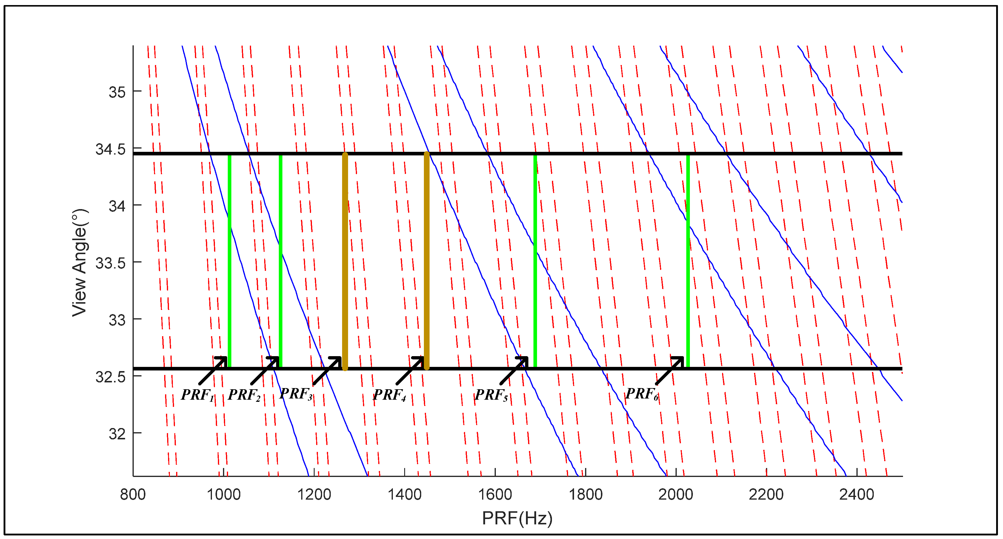
3.1. PRF Design for HRWS SAR-GMTI System with an Ideal Configuration

As for a traditional HRWS-SAR system, the PRF with respect to the ideal configuration in (9) can hardly simultaneously guarantee the avoidance of transmitting pulse shielding and the echo signals of the subsatellite points once the spaceborne radar antenna size is fixed. Different from the traditional HRWS-SAR system with the full-aperture antenna, as shown in Figure 2, the total N channels of the spaceborne HRWS-SAR-GMTI system are uniformly divided into L sets, with each set consisting of Ns subchannels. Firstly, Ns subchannels in each set are used to realize HRWS-SAR imaging, and then L reconstructed SAR images can be obtained to realize the subsequent GMTI processing.
Based on Figure 2, the PRF of the ideal HRWS configuration in (9) can be rewritten as
P R F 2 V s t L a s
where L a s = N s d denotes the sub-aperture antenna size with respect to the HRWS imaging. Then, with a given looking angle, the PRF of the ideal HRWS configuration can be flexibly adjusted within the PRF interval without the influence of the transmitting pulse shielding and nadir echoes by reasonably designing the sub-aperture size L a s .
If we suppose that the initial subchannel number in each HRWS group is N s u b , the optional PRF sets corresponding to the ideal HRWS configuration can be written as
P R F o p t = 2 V s t N s u b 2 d
where N s u b 2 [ 1 , 2 , , N s u b 1 , N s u b ] .
In order to avoid the interference of transmit events and nadir echoes, P R F o p t should also satisfy the following two conditions:
P R F o p t [ j T e 2 T p T g , j + 1 T e 1 + T p + T g ]
P R F o p t [ i T n a d 2 2 h / c T p T g , i + 1 T n a d 1 2 h / c + T p + T g ]
where
T n a d 1 = 2 h / c + i P R T T p T g
T n a d 2 = 2 h / c + i P R T + T p + T g
T e 1 = j P R T T p T g
T e 2 = j P R T + T p + T g
with i, j, Tg and PRT, respectively, denoting the range ambiguity number of the nadir point, the range ambiguity number of the transmitting pulse, the protecting time interval, and the pulse repetition time.
According to (12) and (13), the candidate PRFs with respect to different subchannel numbers Nsub2 in each HRWS set can then be finally selected from the PRF set in (11), leading to different channel grouping schemes. Based on the candidate PRF set, two PRF selection criteria can be listed as follows from the perspective of HRWS imaging and GMTI processing: (1) it is preferable to choose a smaller PRF to ensure a large imaging swath; (2) the group number needs to greater than three, so as to enable HRWS-GMTI system to achieve robust clutter suppression and target relocation.
Based on the above analysis, an example simulation is performed to verify the proposed PRF design method in a spaceborne HRWS SAR-GMTI system. Figure 3 shows the timing diagram, where both the transmit events and the nadir echo are considered. In this simulation, the platform height, the azimuth antenna size, the total channel number, and the elevation angle of the radar beam center are, respectively, set as 1000 km, 33.6 m, 30, and 33.5°. Assume that the initial group number is 3 and that 10 subchannels form a group for HRWS imaging, i.e., N s u b 2 [ 1 , 2 , , 10 ] . According to (10), the PRFs with an ideal HRWS configuration, PRF1~PRF6 corresponding to N s u b 2 being 10, 9, 8, 7, 6, and 5, are labeled in Figure 3, with the PRF values being 1013 Hz, 1125.9 Hz, 1266.7 Hz, 1447.6 Hz, 1688.9 Hz, and 2026.7 Hz, respectively. In light of the constraints in (12) and (13), PRF3 and PRF4 are finally selected as the optimal PRFs, which can satisfy the ideal HRWS configuration and effectively avoid the interference of the transmit events and the nadir echo.

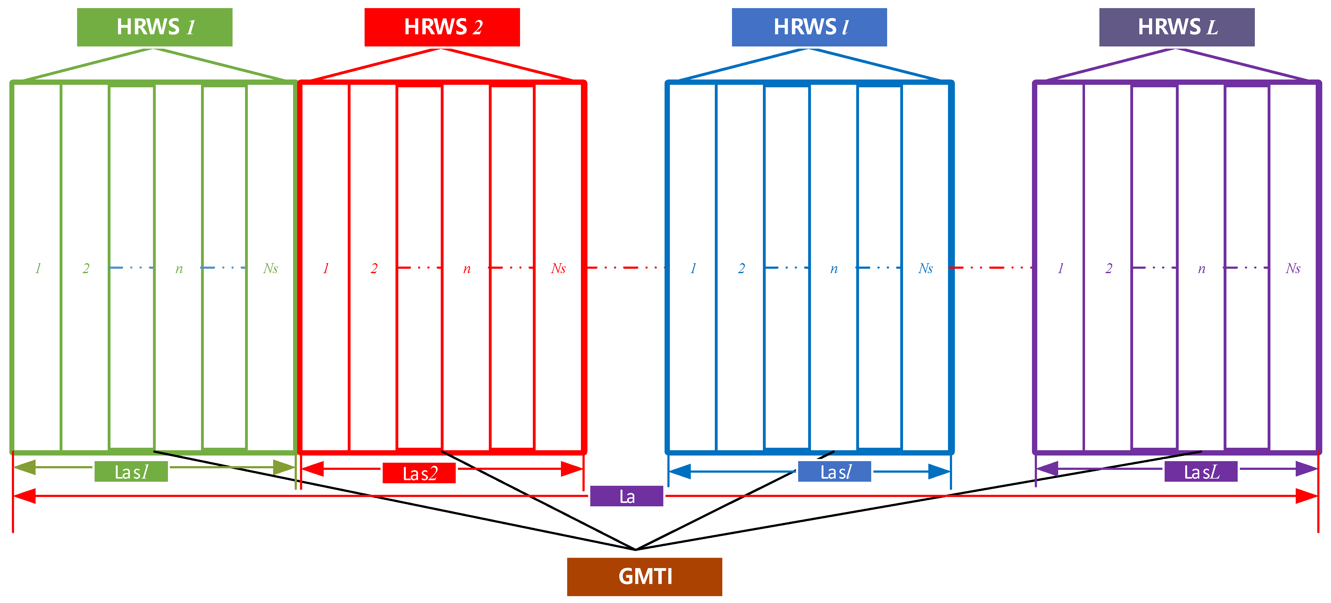
3.2. Wide-Swath Realization in a Spaceborne HRWS-SAR-GMTI System

In virtue of beam scanning the ground from close to far away, the scan-on-receive (SCORE) technique can effectively increase the observation swath. As for the traditional analog domain-based SCORE technique, the transmit beamwidth needs to be broadened and should be greater than the length of a transmitting pulse projected on the ground, unavoidably decreasing the antenna transmission gain. In addition, the radar beam needs to be switched continuously, which may cause signal loss.
To deal with this issue, the digital beamforming (DBF) SCORE technique is adopted in the proposed HRWS-GMTI system design scheme, where the DBF system block diagram is displayed in Figure 4.
As can be seen from Figure 4, the antenna is equipped with NE channels, which can receive radar echo signals and implement the A/D quantization independently. Then, the received signal at the kth range subchannel can be expressed as
s k ( t ) = K 0 r e c t ( t t 0 T p ) exp ( j 2 π f c t 0 ) exp [ j π K r ( t t 0 ) 2 ] × exp [ j 2 π λ d y n sin ( θ R ( t 0 ) θ c ) ]
where K 0 , t 0 , and θ c , respectively, represent the signal amplitude term, reference center time, and normal view angle of the antenna. d y n = ( k N E 1 2 ) d y is the distance of the nth channel with respect to the reference channel along the elevation dimension, where dy denotes the channel spacing between two adjacent channels.
Then, time-variant elevation beam scanning can be realized by using the following time-variant weighting phase in the DBF module (see Figure 4).
ω ( k ) = j 2 π λ d y n sin ( θ R ( t 0 ) θ c )
where θ R ( t 0 ) is the time-variant beam steering, i.e.,
θ R ( t 0 ) = a cos [ R s a t 2 + ( c t 2 ) 2 R t 2 ( t ) 2 R s a t ( c t 2 ) ]
with R s a t and R ( t ) ( R ( t ) = R e + Δ h t ) being the distance from the satellite and observation point to the earth center, respectively. R e and Δ h t denote the earth radius and the elevation of this point relative to the sea level, respectively. The fact that the range DBF can be finished in real time on the satellite can greatly reduce the data downlink burden.

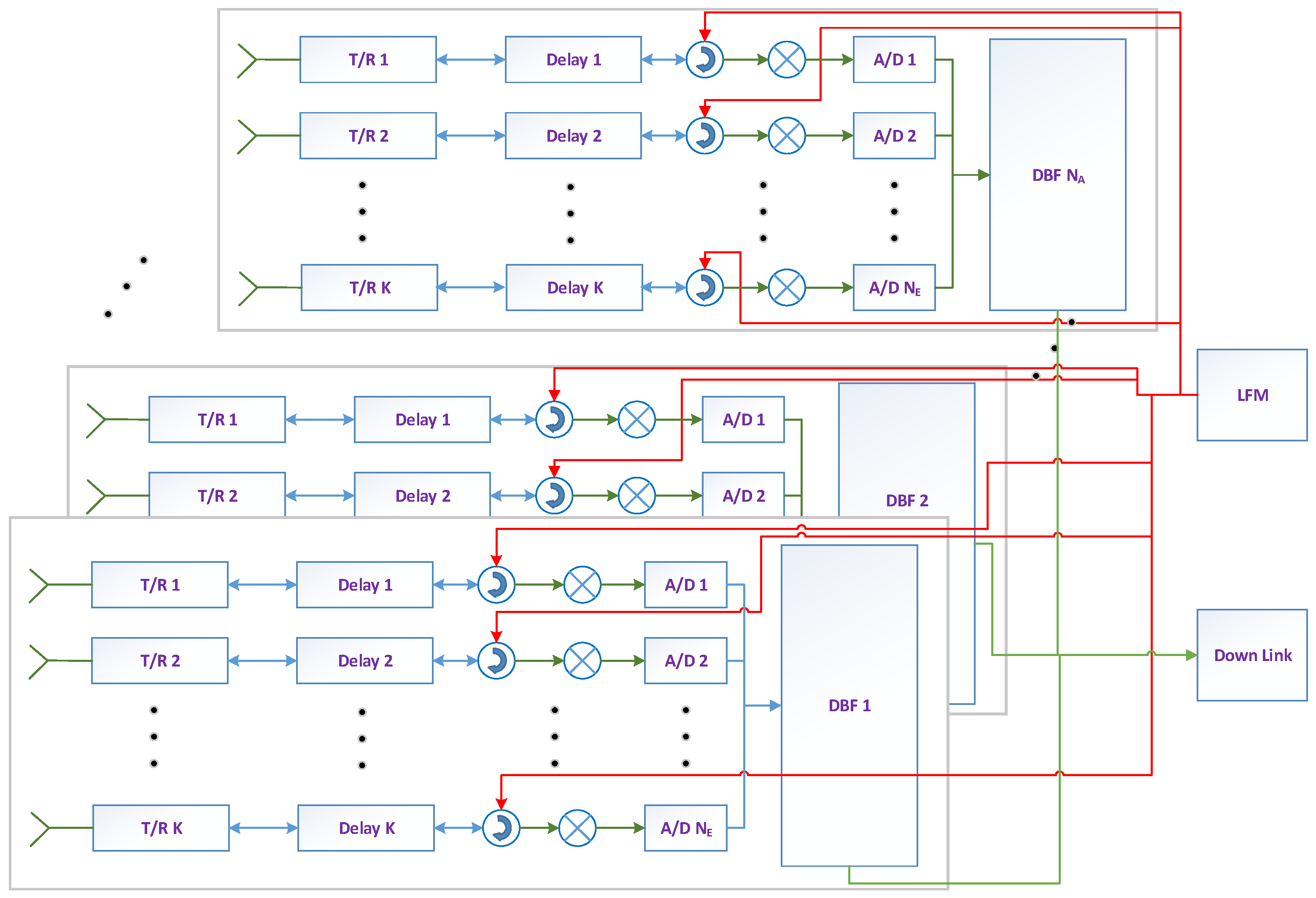
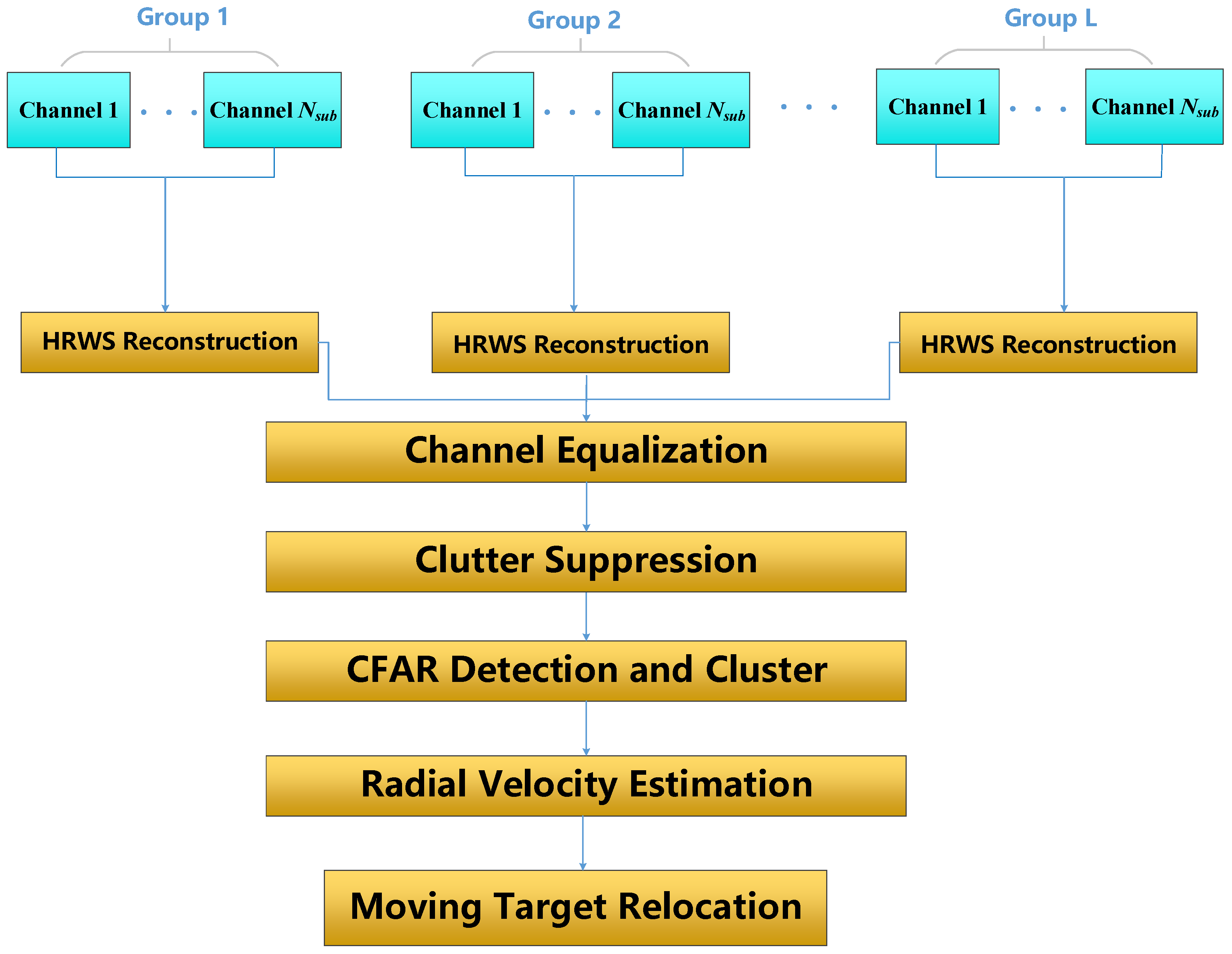
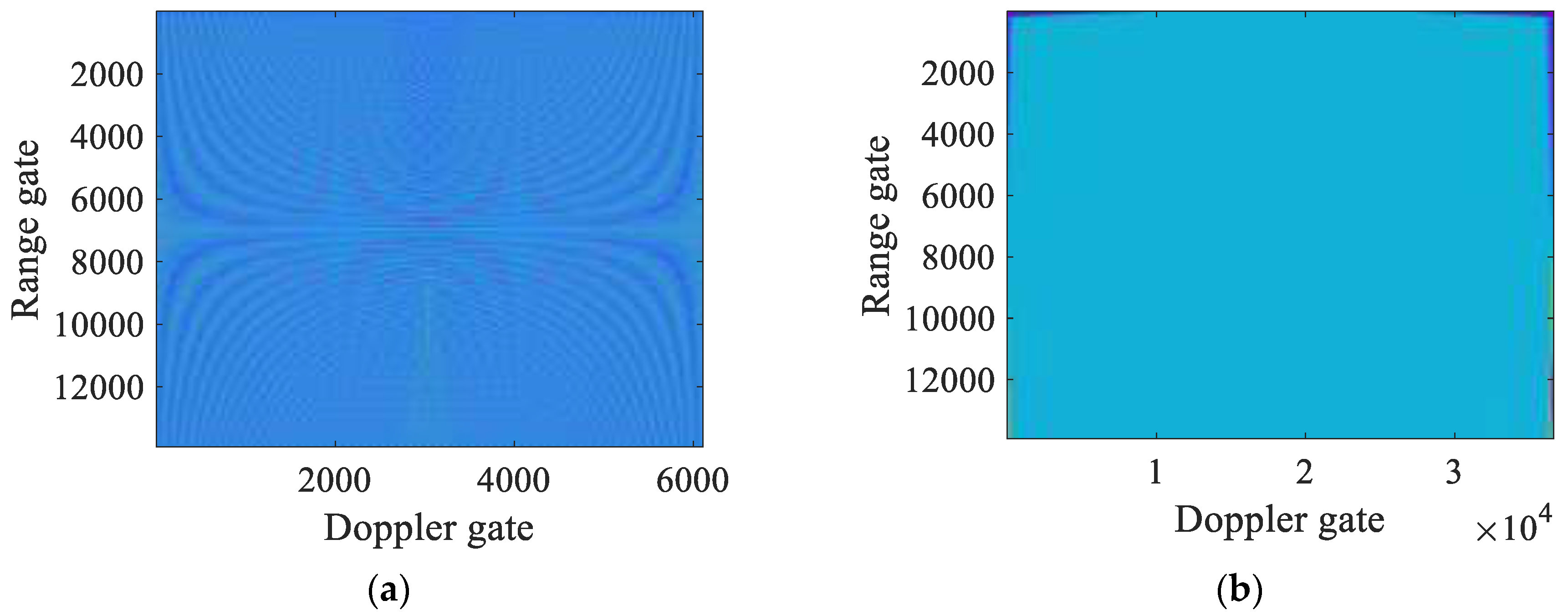
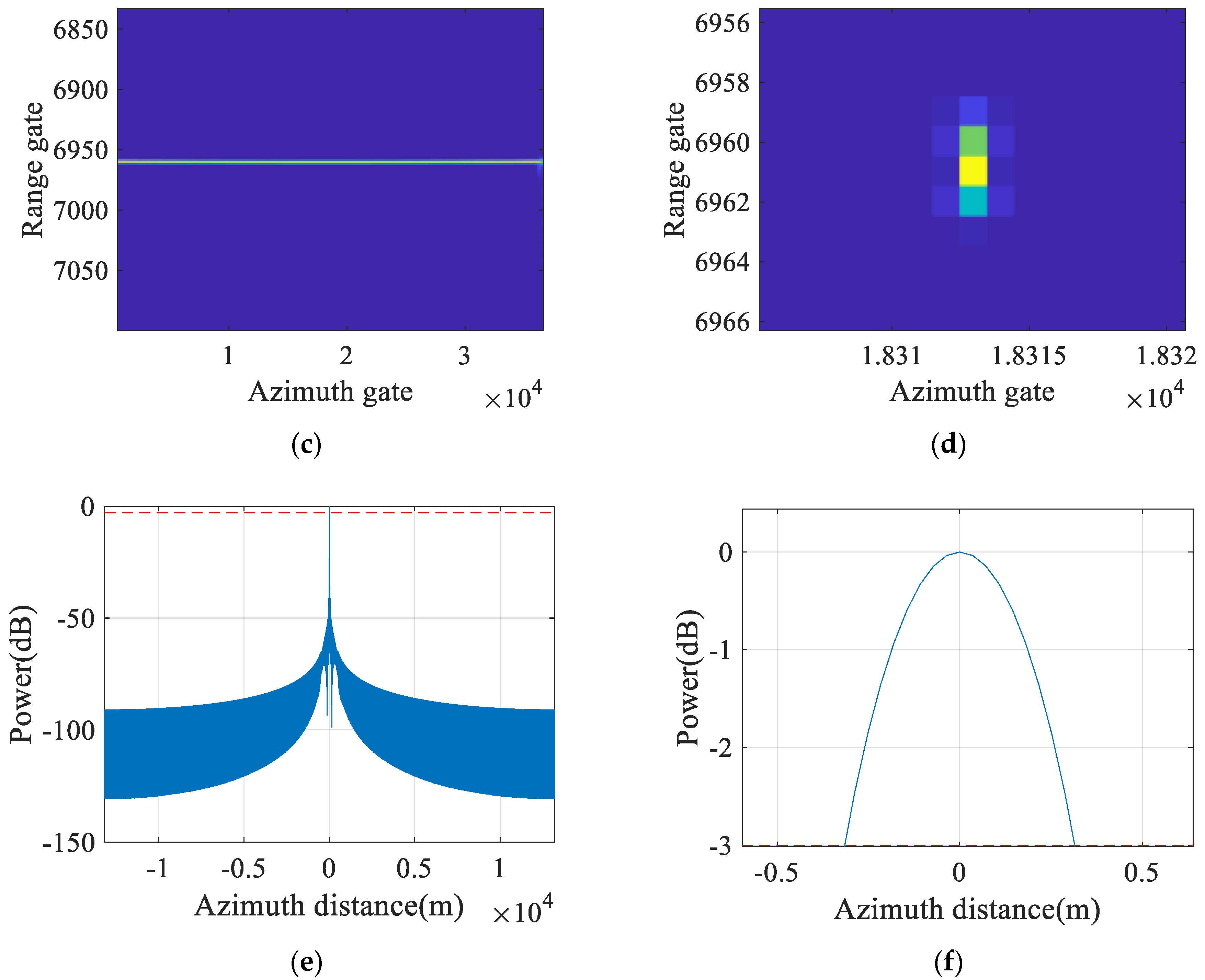
3.3. HRWS-GMTI Implementation

After implementing the radar system design and optimization for a spaceborne HRWS-GMTI system, the received signals can then be used to achieve HRWS-SAR imaging and ground moving target indication. As discussed in Section 3.1, the total N azimuth channels are divided into L groups with Nsub subchannels in each group. As for the HRWS-GMTI system with an ideal configuration, the optimal HRWS reconstruction is performed on these L groups, and the reconstructed signal with respect to the lth group and the kth pulse can be expressed as
s l , r e c o n ( k P R T n e w ) = s l , r e c o n { [ ( k 1 ) N s u b + n s u b ] P R T N s u b } = s ( l 1 ) N s u b + n s u b ( k P R T ) = s 1 ( k P R T + ( l 1 ) N s u b d 2 V s t ) exp ( j 2 π λ d ( l 1 ) N s u b + n s u b v r V s t )
where k = ( k 1 ) N s u b + n s u b and P R T n e w = P R T / N s u b , respectively, correspond to the new azimuth pulse number and PRF after performing the HRWS reconstruction. Then, the reconstructed data with respect to L HRWS SAR images can be further used to achieve GMTI processing, including channel equalization, clutter suppression, CFAR detection, target clustering, and target relocation. Finally, the signal processing flow-chart of the spaceborne HRWS-GMTI system with an ideal configuration is given in Figure 5.

4. Simulation Results and Analysis

In this section, two simulation experiments are designed to validate the proposed method. Based on the optimal reconstruction of the PRF, the working mode of the HRWS-GMTI is constructed and the simulation results of typical transmission beam mode are provided in Section 4.1. And in Section 4.2, the performance analysis of HRWS-GMTI is presented under the typical working mode.

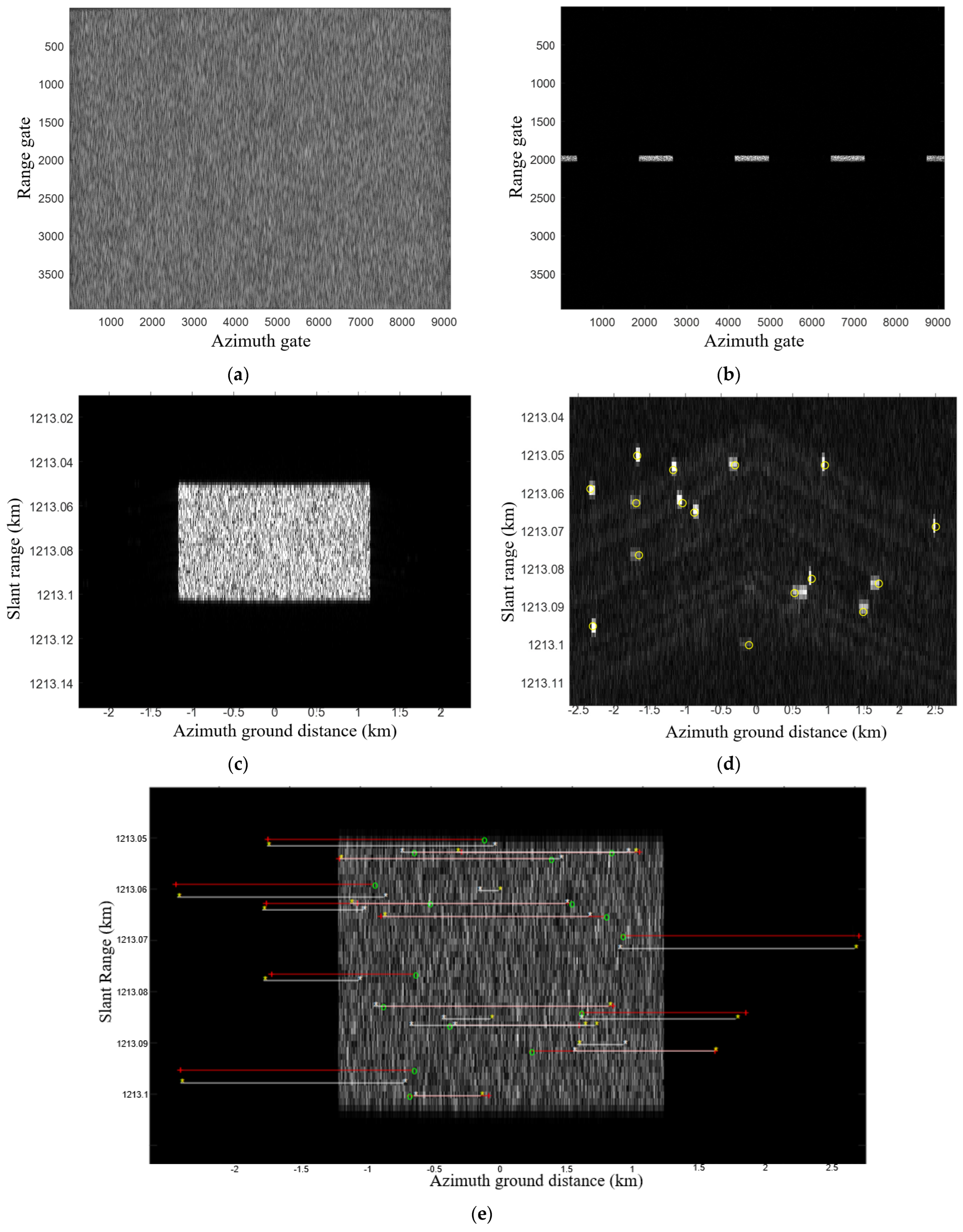
4.1. Experiment for Working Mode of the HRWS-GMTI

In order to demonstrate the effectiveness of the proposed optimal channel grouping method, which can obtain the optimal reconstructed PRF within the full view angle, the simulated multichannel SAR data are calculated with the radar parameters listed in Table 1.
Due to the fact that the echo signal from the satellite point can be suppressed by properly designing the range pattern, the timing chart only considers the interference of transmitted pulses. Figure 6a displays the result of PRF selection satisfying the optimal reconstruction conditions, where the green curve represents six types of optimal reconstruction PRF and the blue curve represents the selection results corresponding to a typical view angle. From Figure 6b, a total of 26 typical beams are selected and the optimal PRFs are calculated for each beam, respectively, and listed in Table 2.
Suppose that the system resolution is fixed as 1 m in each beam, which can be realized by adjusting the system bandwidth and transmitting antenna size. Figure 7a,b show the NESZ values and SNR values of the selected beams with view angles ranging from 15.55° to 51.05°, from which it can be seen that the typical beam with a lower NESZ can achieve a higher SNR, beneficial for moving target detection.

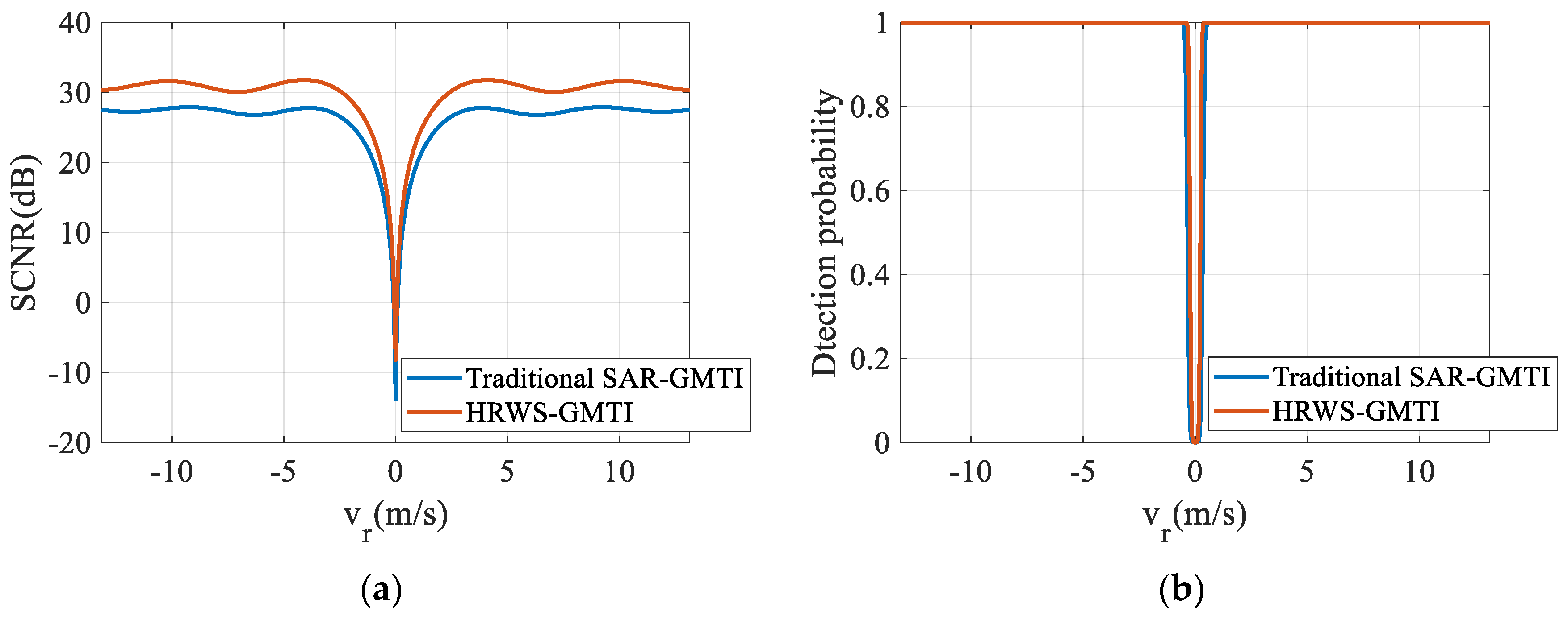
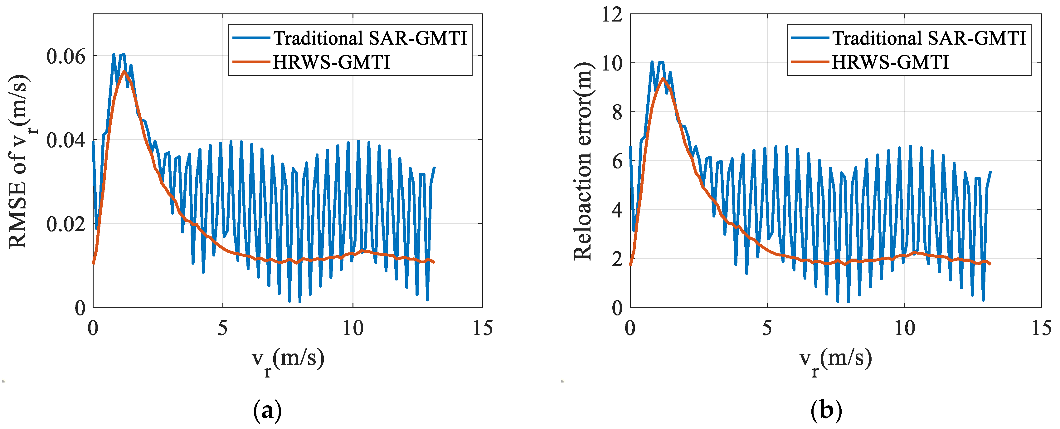
4.2. HRWS-GMTI Performance Analysis

In the following, the imaging resolution of the HRWS-GMTI SAR system is firstly discussed, and then the GMTI processing results and GMTI performance are, respectively, presented and evaluated. The SAR parameters are listed in Table 2 and the observation scene is assumed to be the monitoring of vehicles on an expressway. The other parameters such as the antenna size, number of channels, signal bandwidth, and height of spaceborne orbit are given in Table 1. A typical view angle of 22.9° is selected, and 30 azimuth channels are divided into five groups to complete the GMTI task, where HRWS-SAR imaging is realized by six channels within each group. Twenty moving point targets with an average speed of a car on an expressway, i.e., 80 km/h corresponding to 23 m/s, are simulated (the size, velocity direction, and initial position of the moving targets are randomly allocated), where the clutter background is grassland.
Figure 8 shows the HRWS imaging results as statistic scatter points. From the figures, it can be seen that the unambiguous SAR image can finally be reconstructed by interpolating the undersampling signal with spatial points along the azimuth dimension [20,21]. Then, based on the half power point in Figure 8f, the azimuth resolution can be estimated as about 0.64 m (the theoretical value is 0.7 m). Therefore, the resolution requirement of less than 1 m resolution can finally be achieved by reasonably designing the system parameters by the proposed method.
Figure 9a–e show the simulation results of the original echo signal, pre-reconstruction SAR image, reconstructed SAR image, moving target detection, and moving target repositioning, respectively. It is observed that 16 out of 20 moving targets are successfully detected. The radial velocities of four targets are less than 1.9 m/s, which are not effectively detected by using the cell averaging–constant false alarm rate (CA-CFAR) technique. Due to the influence of clutter suppression and Doppler diffusion, the target output SNR is significantly reduced. After repositioning, the maximum positioning error of these targets is less than 400 m.
According to Table 3, the target detection performance and relocation performance of the traditional SAR-GMTI system with all the 30 channels used for GMTI processing and the proposed HRWS-GMTI method are, respectively, analyzed in Figure 10 and Figure 11. As can be seen from the comparative output SCNRs and target detection probabilities in Figure 10a,b, the proposed HRWS-GMTI method can obtain better target detection performance than that of the traditional SAR-GMTI method since HRWS processing reduces the energy loss of the spatial mismatch during the clutter suppression procedure. Since the target output SNR is relatively high in this simulation experiment, both the proposed HRWS-GMTI method and the traditional SAR-GMTI method can obtain satisfactory target relocation performance (see Figure 11). Therefore, the proposed HRWS-SAR-GMTI system design and signal processing method can not only realize wide-area imaging and target surveillance, but can also obtain relatively better GMTI performance than that of the traditional SAR-GMTI method.

5. Conclusions

In this paper, we have proposed an HRWS-SAR-GMTI design method that satisfies the optimal reconstruction conditions. The main contributions of the proposed method include the following: (1) the proposed method enables the detection and imaging of ground moving targets over a large search area in an HRWS-SAR system; (2) the proposed method can realize the optimal PRF design based on a reasonable antenna channel design; (3) the proposed HRWS-GMTI system can achieve superior GMTI performance to traditional SAR-GMTI performance. The experimental results have verified the effectiveness of the proposed method. The typical target signal reconstruction methods of the HRWS-GMTI system are used to solve target reconstruction filter mismatch problems, which may induce large computation burden in practical processing. Therefore, how to efficiently address the target reconstruction filter mismatch problem without consuming too many system resources will be part of our future investigation.

Author Contributions

Conceptualization, Y.J., J.M., X.L. and J.F.; methodology, Y.J. and L.W.; software, Y.J. and L.W.; validation, Y.J. and L.W.; formal analysis, P.H., Q.L. and L.W.; investigation, J.F.; resources, Y.J.; data curation, Y.J. and J.M.; writing—original draft preparation, Y.J.; writing—review and editing, P.H., Q.L. and L.W.; visualization, Q.L.; supervision, X.L.; project administration, Y.J.; funding acquisition, Y.J. All authors have read and agreed to the published version of the manuscript.

Funding

This work was supported in part by the National Key R&D Program of China (No. 2022YFB3902300).

Data Availability Statement

The data that support the findings of this study are available on request from the corresponding author. The data are not publicly available due to privacy or ethical restrictions.

Conflicts of Interest

Author Yan Jiang is studying simultaneously at a research institution named the Shanghai Academy of Spaceflight Technology. The remaining authors declare that the research was conducted in the absence of any commercial or financial relationships that could be construed as a potential conflict of interest.

Abbreviations

The following abbreviations are used in this manuscript:
HRWS-SARHigh-Resolution Wide Swath Synthetic Aperture Rada
GMTIGround Moving Target Indication
DPCADisplaced Phase Center Antenna
PRFPulse Repetition Frequency
DBFDigital Beam Forming
SCOREScanning on Receive
NESZNoise equivalent scattering coefficient
ATIAlong-track interferometric
SCNRSignal to clutter plus noise ratio
MRBFMatched reconstruction filter bank
SNRSignal-to-noise ratio

References

  1. Raney, R.K. Synthetic Aperture Imaging Radar and Moving Targets. IEEE Trans. AES 1971, 3, 499–505. [Google Scholar] [CrossRef]
  2. Lee, J.S.; Hoppel, K.W.; Mango, S.A.; Miller, A.R. Intensity and phase statistics of multilook polarimetric and interferometric SAR imagery. IEEE Trans. Geosci. Remote Sens. 1994, 32, 1017–1028. [Google Scholar] [CrossRef]
  3. Budillon, A.; Evangelista, A.; Schirinzi, G. GLRT detection of moving targets via multi-baseline along track interferometric SAR systems. IEEE Geosci. Remote Sens. Lett. 2012, 9, 348–352. [Google Scholar] [CrossRef]
  4. Zheng, M.J.; Yang, R.L. An improved DPCA moving targets detecting algorithm. Acta Electron. Sin. 2004, 32, 1429–1432. [Google Scholar] [CrossRef]
  5. Yi, C.; Bo, Q.; Shengli, W. DPCA motion compensation technique based on multiple phase centers. In Proceedings of the 2011 IEEE CIE International Conference on Radar, Chengdu, China, 24–27 October 2011; pp. 711–714. [Google Scholar] [CrossRef]
  6. Brennan, L.E.; Reed, L.S. Theory of adaptive radar. IEEE Trans. Aerosp. Electron. Syst. 1973, 9, 237–252. [Google Scholar] [CrossRef]
  7. Shu, Y.; Liao, G.; Yang, Z. Design Considerations of PRF for Optimizing GMTI Performance in Azimuth Multichannel SAR Systems with HRWS Imaging Capability. IEEE Trans. Geosci. Remote Sens. 2014, 52, 2048–2063. [Google Scholar]
  8. Baumgartner, S.V.; Krieger, G. Simultaneous High-Resolution Wide-Swath SAR Imaging and Ground Moving Target Indication: Processing Approaches and System Concepts. IEEE J. Sel. Top. Appl. Earth Obs. Remote Sens. 2015, 8, 5015–5029. [Google Scholar] [CrossRef]
  9. Xing, M.; Sun, G.; Li, X. Study on SAR/GMTI Processing for High-Resolution Wide-Swath SAR System. J. Radars 2015, 4, 375–385. [Google Scholar]
  10. Zhang, S.X.; Xing, M.D.; Xia, X.G.; Guo, R.; Liu, Y.Y.; Bao, Z. Robust Clutter Suppression and Moving Target Imaging Approach for Multichannel in Azimuth High-Resolution and Wide-Swath Synthetic Aperture Radar. IEEE Trans. Geosci. Remote Sens. 2015, 53, 687–709. [Google Scholar] [CrossRef]
  11. Yang, T.; Wang, Y.; Li, W. A Moving Target Imaging Algorithm for HRWS SAR/GMTI Systems. IEEE Trans. Aerosp. Electron. Syst. 2017, 53, 1147–1157. [Google Scholar] [CrossRef]
  12. Hou, L.; Zhang, Q. GMTI Processing for Multi-Channel High-Resolution Wide-Swath SAR Systems. Remote Sens. Lett. 2019, 10, 21–29. [Google Scholar] [CrossRef]
  13. Zhang, S.; Jiang, Z.; Chen, J.; Li, S.; Liu, Y.; Guo, R.; Xing, M. An Effective Clutter Suppression Approach Based on Null-Space Technique for the Space-Borne Multichannel in Azimuth High-Resolution and Wide-Swath SAR System. IEEE Trans. Geosci. Remote Sens. 2022, 60, 5211428. [Google Scholar] [CrossRef]
  14. Zhang, Z.; Yu, W.; Zheng, M.; Zhao, L.; Zhou, Z.X. Robust Clutter Suppression and Radial Velocity Estimation for High-Resolution Wide-Swath SAR-GMTI. Remote Sens. 2022, 14, 1555. [Google Scholar] [CrossRef]
  15. Ender, J.; Klare, J. System architectures and algorithms for radar imaging by MIMO-SAR. In Proceedings of the 2009 IEEE Radar Conference, Pasadena, CA, USA, 4–8 May 2009. [Google Scholar]
  16. Huang, P.; Xia, X.G.; Wang, L.; Xu, H.; Liu, X.; Liao, G.; Jiang, X. Imaging and Relocation for Extended Ground Moving Targets in Multichannel SAR-GMTI Systems. IEEE Trans. Geosci. Remote Sens. 2021, 60, 5214024. [Google Scholar] [CrossRef]
  17. Ender, J.H.G. The airborne experimental multi-channel SAR system AER-II. In Proceedings of the EUSAR Conference, Koenigswinter, Germany, 26–28 March 1996; pp. 49–52. [Google Scholar]
  18. Ji, P.; Xing, S.; Dai, D.; Pang, B.; Feng, D. A Smart Multitransmitter Cooperative False Images Generation Method Against Multichannel SAR-GMTI. IEEE Trans. Geosci. Remote Sens. 2024, 62, 5204017. [Google Scholar] [CrossRef]
  19. Gebert, N.; Krieger, G.; Moreira, A. Digital Beamforming on Receive: Techniques and Optimization Strategies for High-Resolution Wide-Swath SAR Imaging. Aerosp. Electron. Syst. IEEE Trans. 2009, 45, 564–592. [Google Scholar] [CrossRef]
  20. Huang, H.; Huang, P.; Liu, X.; Xia, X.G.; Deng, Y.; Fan, H.; Liao, G. A Novel Channel Errors Calibration Algorithm for Multichannel High-Resolution and Wide-Swath SAR Imaging. IEEE Trans. Geosci. Remote Sens. 2021, 60, 5201619. [Google Scholar] [CrossRef]
  21. Raney, R.K.; Runge, H.; Bamler, R.; Cumming, I.G.; Wong, F.H. Precision SAR processing using chirp scaling. Geosci. Remote Sens. IEEE Trans. 1994, 32, 786–799. [Google Scholar] [CrossRef]
Figure 1. The 3D geometry relationship between a spaceborne multichannel SAR-GMTI platform and a ground moving target.
Remotesensing 16 02148 g001
Figure 2. The channel grouping diagram in a spaceborne HRWS SAR-GMTI system.
Remotesensing 16 02148 g002
Figure 3. Timing diagram considering both the transmit events and the nadir echo, where the red dashed line, blue solid line, green line, and brown line, respectively, denote the transmit events, nadir echo, candidate PRFs, and optimal PRFs.
Remotesensing 16 02148 g003
Figure 4. The DBF system block diagram, with red lines, green lines, and blues line denoting the transmitting link, the receiving link, and transmit–receive link, respectively.
Remotesensing 16 02148 g004
Figure 5. The signal processing flow-chart of spaceborne HRWS-GMTI with an ideal configuration.
Remotesensing 16 02148 g005
Figure 6. PRF selection results satisfying the optimal reconstruction conditions. (a) The optimal timing chart of PRF selection (the green curve represents six types of optimal reconstruction PRF and the blue curve denots the selection results corresponding to a typical view angle). (b) Selected PRF for each beam.
Remotesensing 16 02148 g006
Figure 7. NESZ and SNR for each selected beam (RCS is 10 dBm2). (a) NESZ for each selected beam. (b) SNR for each selected beam.
Remotesensing 16 02148 g007
Figure 8. HRWS imaging results as statistic scatter points. (a) The aliasing Doppler spectrum of the scatter point signal before performing the range compression. (b) The reconstructed Doppler spectrum of the scatter point signal after performing the HRWS reconstruction. (c) The reconstructed scatter point signal after performing range compression and range migration correction by using the chirp scaling (CS) technique [21]. (d) The focused scatter point signal after performing the azimuth compression. (e) The 1D range profile of the focused scatter point signal. (f) The magnified image of (e) near the peak point.
Remotesensing 16 02148 g008aRemotesensing 16 02148 g008b
Figure 9. HRWS GMTI processing results satisfying the optimal reconstruction conditions. (a) Original echo signal. (b) Pre-reconstruction SAR image (channel 1). (c) Reconstructed SAR image. (d) Result of moving target detection. (e) Result of moving target repositioning (The red plus sign represents the actual detected position. The green circle is the actual positioning position, and the yellow and white asterisks denote the target offset position and the real target position set in advance, respectively).
Remotesensing 16 02148 g009
Figure 10. Target detection performance analysis. (a) Output target SCNRs with respect to different radial velocities. (b) Detection probabilities with respect to different radial velocities.
Remotesensing 16 02148 g010
Figure 11. Target relocation performance analysis. (a) Radial velocity estimation RMSEs with respect to different radial velocities. (b) Relocation errors with respect to different radial velocities.
Remotesensing 16 02148 g011
Table 1. Simulated multichannel SAR parameters.
ParametersValues
Height of orbit 1100 km
Carrier frequency9.6 GHz
Signal bandwidth≤400 MHz
Number of antenna channels (A × R)30 × 128
Channel number of HRWS (A)4~10
Channel number of GMTI (A)≥3
Antenna size (A × R)43.2 m × 2.6 m
Range of view angle15.55°~51.05°
Resolution/swath≤1 m/(60 km~120 km)
Table 2. The optimal PRF selection results for each beam.
Beam NumberView AngleAzimuth Channel NumberOptimal PRF
115.55°271126.6 Hz
218.31°211448.4 Hz
320.36°211448.4 Hz
422.92°301013.3 Hz
524.82°301013.3 Hz
627.159°301013.3 Hz
728.89°211448.4 Hz
831°241266.3 Hz
932.56°301013.3 Hz
1034.45°301013.3 Hz
1135.84°301013.3 Hz
1237.52°241266.3 Hz
1338.77°301013.3 Hz
1440.25°301013.3 Hz
1541.35°241266.3 Hz
1642.67°271126.6 Hz
1743.64°301013.3 Hz
1844.8°301013.3 Hz
1945.66°271126.6 Hz
2046.67°301013.3 Hz
2147.43°301013.3 Hz
2248.33°271126.6 Hz
2348.99°271126.6 Hz
2449.78°301013.3 Hz
2550.36°271126.6 Hz
2651.05°301013.3 Hz
Table 3. HRWS-SAR parameters.
ParametersValues
Channel number of HRWS operation (A)6
Channel number of GMTI operation (A)5
Elevation angle of moving targets22.9°
The optimal PRF1694.4 Hz
RCS of moving point targets10 dBm2
Clutter backgroundGrassland (RCS is considered with −10 dB)
Disclaimer/Publisher’s Note: The statements, opinions and data contained in all publications are solely those of the individual author(s) and contributor(s) and not of MDPI and/or the editor(s). MDPI and/or the editor(s) disclaim responsibility for any injury to people or property resulting from any ideas, methods, instructions or products referred to in the content.

