
Drone-Based Ground-Penetrating Radar with Manual Transects for Improved Field Surveys of Buried Ice

 ,
,  , , ,
, , ,
Abstract
:1. Introduction
1.1. Ground-Penetrating Radar for Surveying Buried Ice
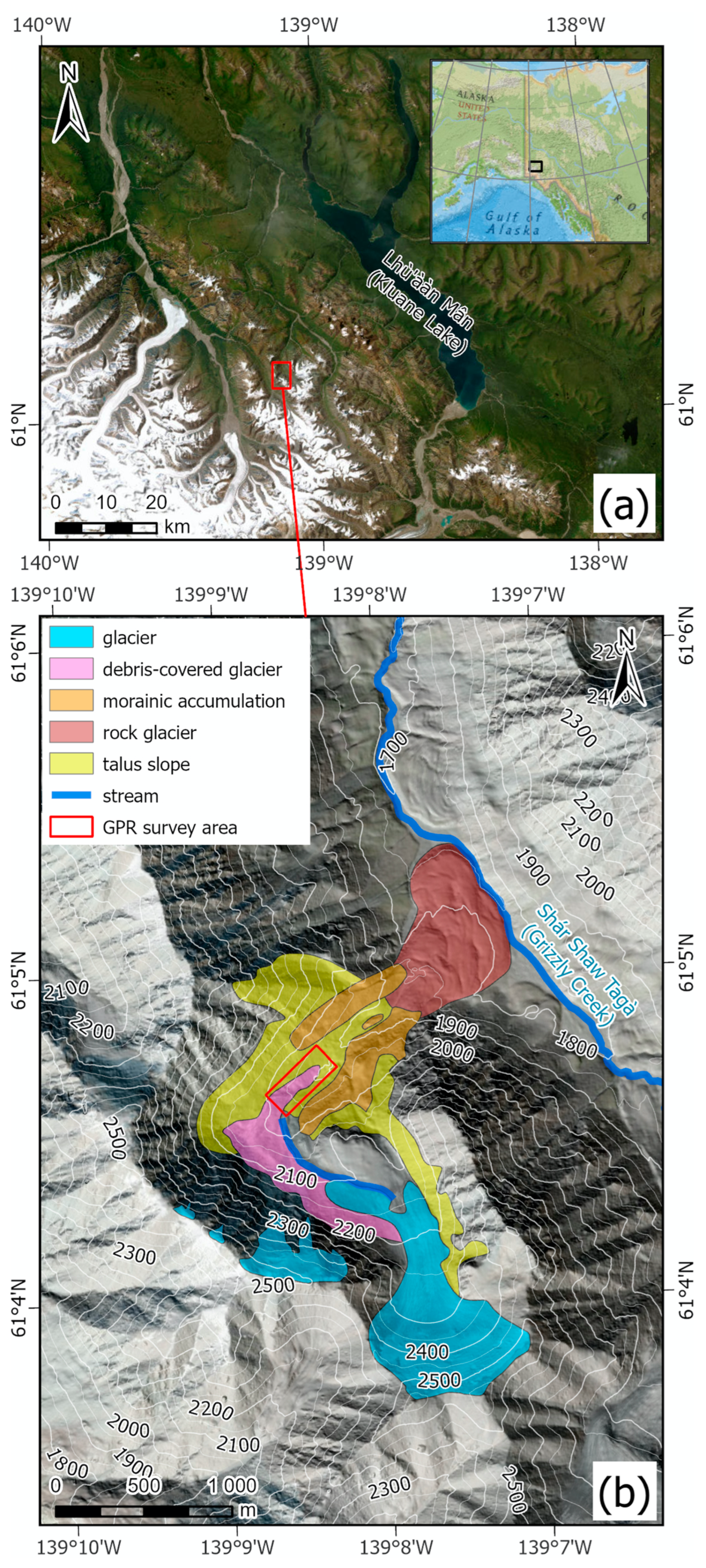
1.2. Shár Shaw Tagà (Grizzly Creek) Field Site
2. Materials and Methods
2.1. Drone-Based GPR
2.2. Manual Ground-Penetrating Radar
2.3. Drone Photgrammetry and DEM
2.4. Radar Data Processing
2.5. Measuring Buried Ice Heights and Depths
3. Results
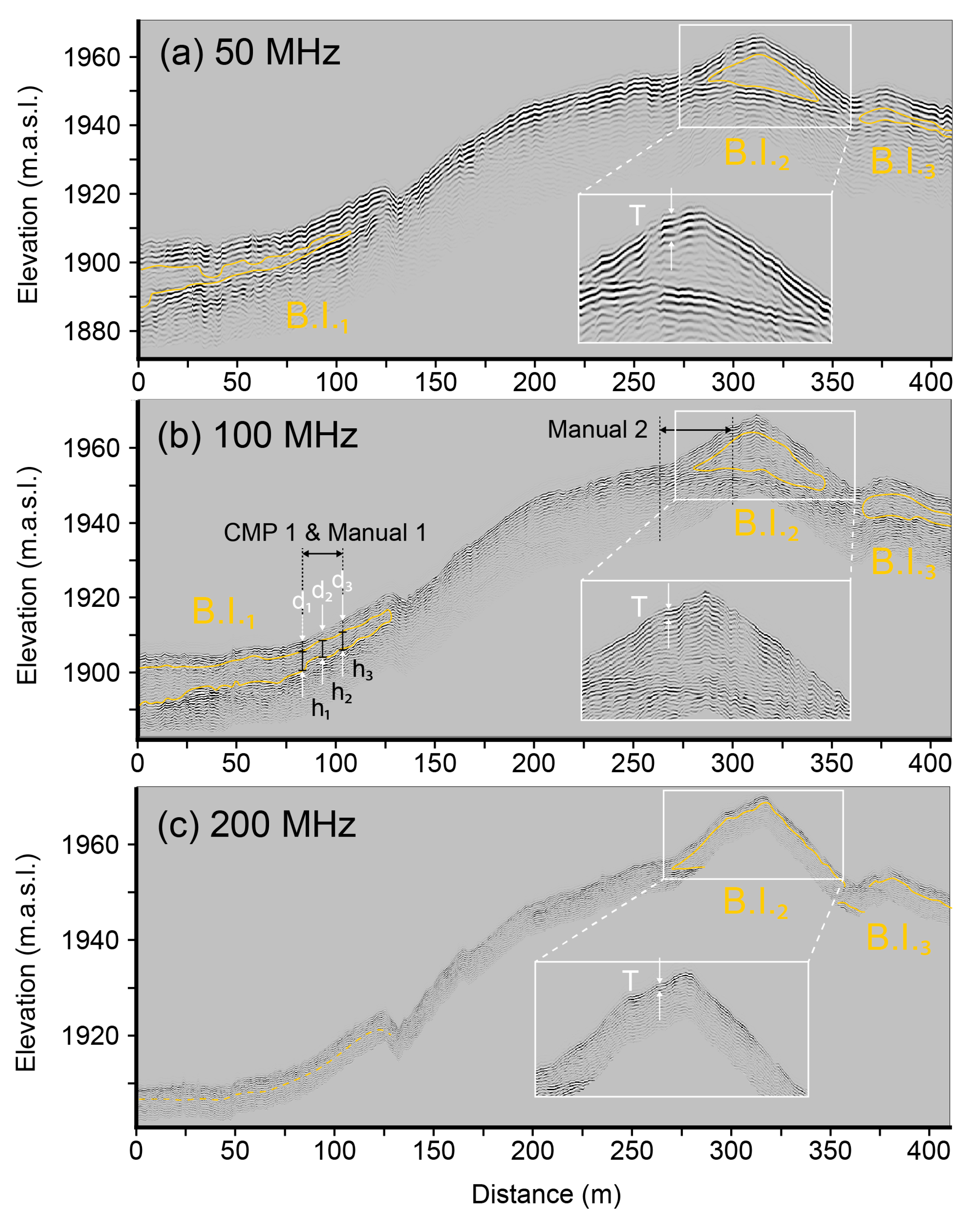
3.1. Drone-Based Radargrams
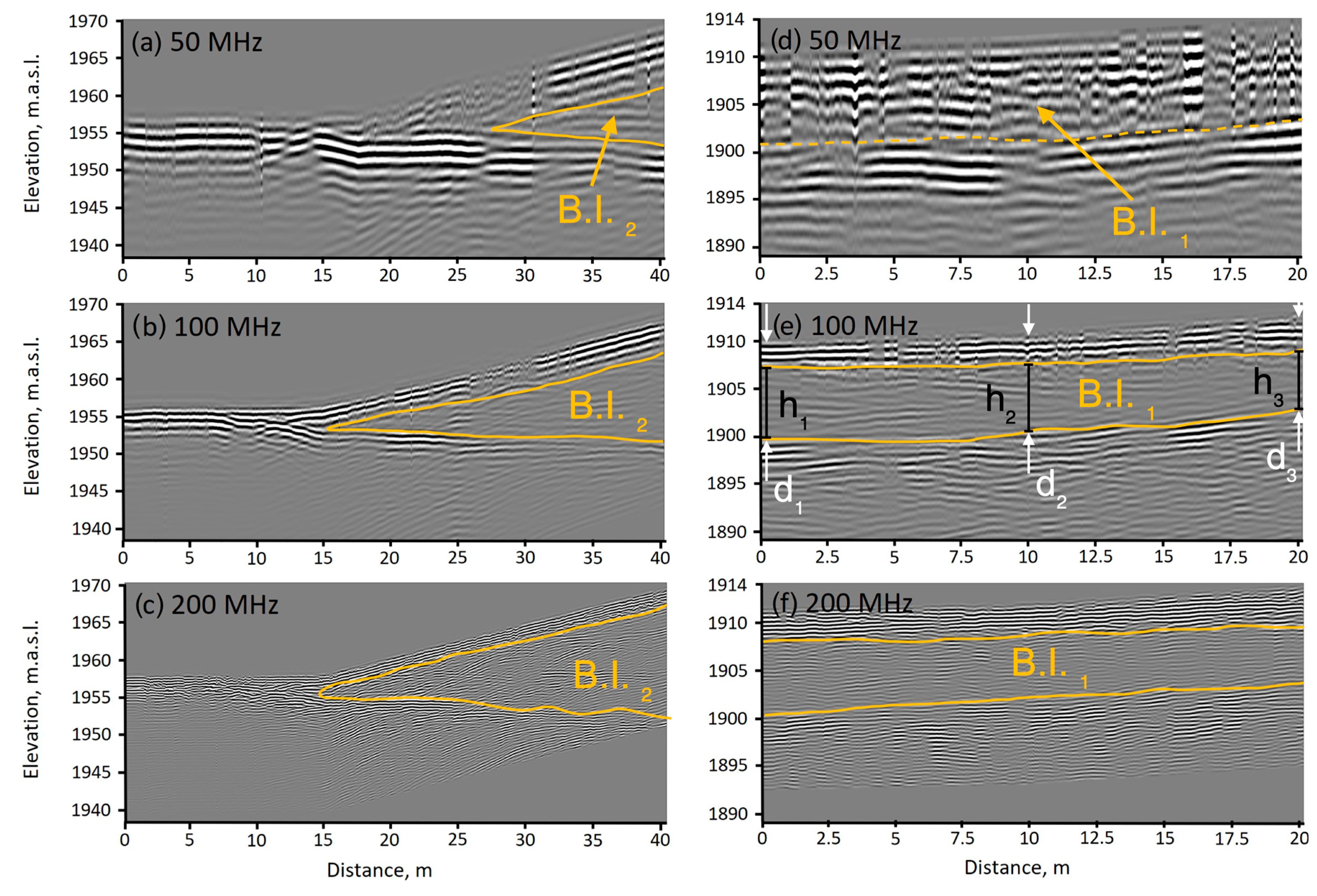
3.2. Manual Radargrams
3.3. Height and Depth Measurements
4. Discussion
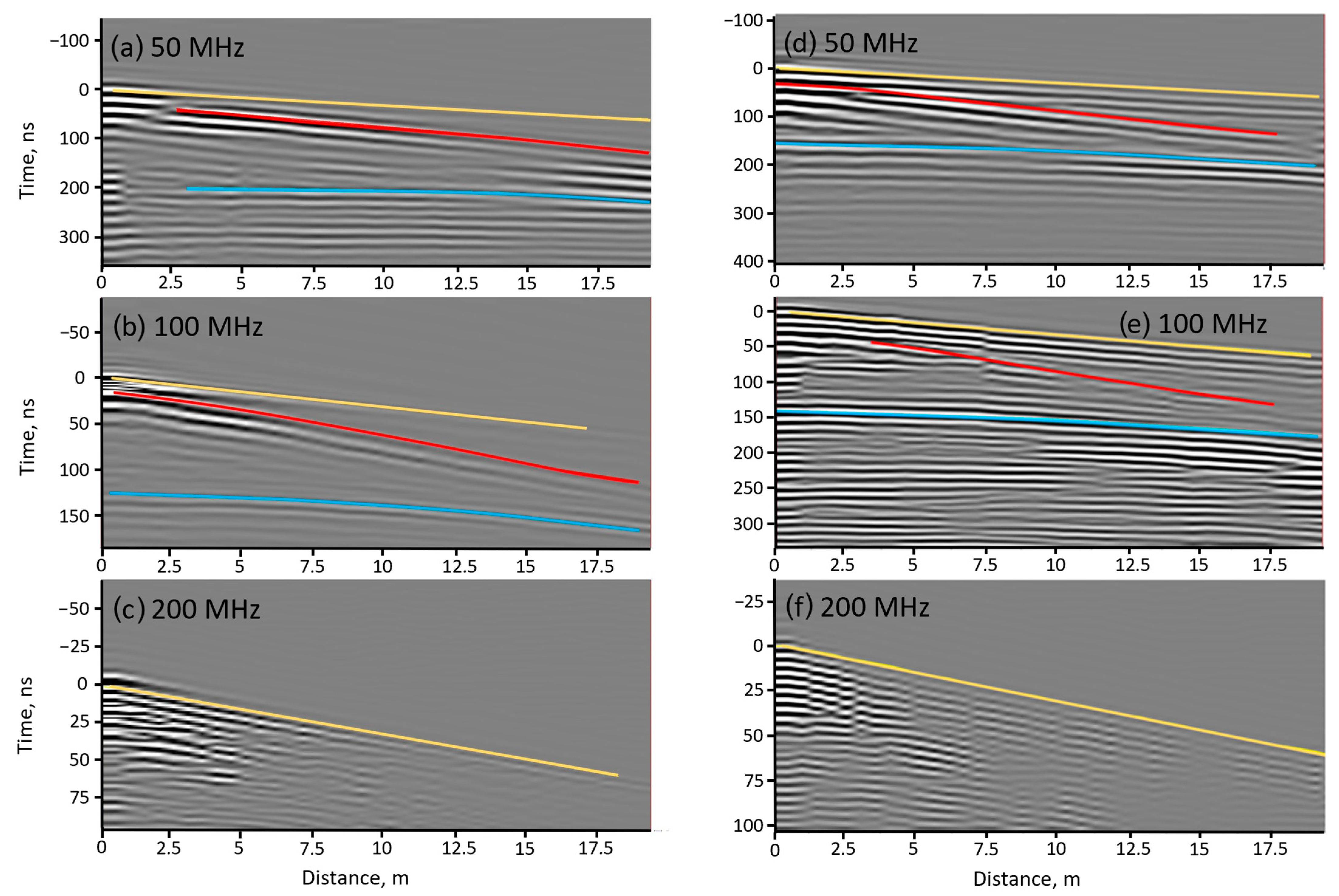
4.1. CMP Results
4.2. Differences between Drone and Manual GPR Measurements
4.2.1. Uncertainty Related to Aerial GPR Operation
4.2.2. Other Sources of Uncertainty
4.3. Methodological Recommendations
5. Conclusions
Supplementary Materials
Author Contributions
Funding
Data Availability Statement
Acknowledgments
Conflicts of Interest
References
- Herreid, S.; Pellicciotti, F. The State of Rock Debris Covering Earth’s Glaciers. Nat. Geosci. 2020, 13, 621–627. [Google Scholar] [CrossRef]
- Everest, J.; Bradwell, T. Buried Glacier Ice in Southern Iceland and Its Wider Significance. Geomorphology 2003, 52, 347–358. [Google Scholar] [CrossRef]
- Paul, F.; Huggel, C.; Kääb, A. Combining Satellite Multispectral Image Data and a Digital Elevation Model for Mapping Debris-Covered Glaciers. Remote Sens. Environ. 2004, 89, 510–518. [Google Scholar] [CrossRef]
- Xie, Z.; Haritashya, U.K.; Asari, V.K.; Young, B.W.; Bishop, M.P.; Kargel, J.S. GlacierNet: A Deep-Learning Approach for Debris-Covered Glacier Mapping. IEEE Access 2020, 8, 83495–83510. [Google Scholar] [CrossRef]
- Jones, D.B.; Harrison, S.; Anderson, K.; Whalley, W.B. Rock Glaciers and Mountain Hydrology: A Review. Earth-Sci. Rev. 2019, 193, 66–90. [Google Scholar] [CrossRef]
- Mertes, J.R.; Thompson, S.S.; Booth, A.D.; Gulley, J.D.; Benn, D.I. A Conceptual Model of Supra-Glacial Lake Formation on Debris-Covered Glaciers Based on GPR Facies Analysis: GPR Facies Analysis of Spillway Lake, Ngozumpa Glacier, Nepal. Earth Surf. Process. Landf. 2017, 42, 903–914. [Google Scholar] [CrossRef]
- Strickland, R.M.; Covington, M.D.; Gulley, J.D.; Kayastha, R.B.; Blackstock, J.M. Englacial Drainage Drives Positive Feedback Depression Growth on the Debris-Covered Ngozumpa Glacier, Nepal. Geophys. Res. Lett. 2023, 50, e2023GL104389. [Google Scholar] [CrossRef]
- Berthling, I.; Etzelmüller, B.; Isaksen, K.; Sollid, J.L. Rock Glaciers on Prins Karls Forland. II: GPR Soundings and the Development of Internal Structures. Permafr. Periglac. Process. 2000, 11, 357–369. [Google Scholar] [CrossRef]
- Brandt, O.; Langley, K.; Kohler, J.; Hamran, S.-E. Detection of Buried Ice and Sediment Layers in Permafrost Using Multi-Frequency Ground Penetrating Radar: A Case Examination on Svalbard. Remote Sens. Environ. 2007, 111, 212–227. [Google Scholar] [CrossRef]
- De Pascale, G.P.; Pollard, W.H.; Williams, K.K. Geophysical Mapping of Ground Ice Using a Combination of Capacitive Coupled Resistivity and Ground-Penetrating Radar, Northwest Territories, Canada. J. Geophys. Res. 2008, 113, F02S90. [Google Scholar] [CrossRef]
- Degenhardt, J.J. Development of Tongue-Shaped and Multilobate Rock Glaciers in Alpine Environments—Interpretations from Ground Penetrating Radar Surveys. Geomorphology 2009, 109, 94–107. [Google Scholar] [CrossRef]
- Capt, M.; Bosson, J.-B.; Fischer, M.; Micheletti, N.; Lambiel, C. Decadal Evolution of a Very Small Heavily Debris-Covered Glacier in an Alpine Permafrost Environment. J. Glaciol. 2016, 62, 535–551. [Google Scholar] [CrossRef]
- Petersen, E.I.; Levy, J.S.; Holt, J.W.; Stuurman, C.M. New Insights into Ice Accumulation at Galena Creek Rock Glacier from Radar Imaging of Its Internal Structure. J. Glaciol. 2020, 66, 1–10. [Google Scholar] [CrossRef]
- Merz, K.; Green, A.G.; Buchli, T.; Springman, S.M.; Maurer, H. A New 3-D Thin-skinned Rock Glacier Model Based on Helicopter GPR Results from the Swiss Alps. Geophys. Res. Lett. 2015, 42, 4464–4472. [Google Scholar] [CrossRef]
- Blindow, N.; Salat, C.; Casassa, G. Airborne GPR Sounding of Deep Temperate Glaciers — Examples from the Northern Patagonian Icefield. In Proceedings of the 2012 14th International Conference on Ground Penetrating Radar (GPR), Shanghai, China, 4–8 June 2012; pp. 664–669. [Google Scholar]
- Casassa, G.; Rodríguez, J.L.; Blindow, N. Airborne GPR on High Andean Glaciers—First Results from 6000 m Altitude. In Proceedings of the 15th International Conference on Ground Penetrating Radar, Brussels, Belgium, 30 June–4 July 2014; pp. 728–733. [Google Scholar]
- Langhammer, L.; Rabenstein, L.; Schmid, L.; Bauder, A.; Grab, M.; Schaer, P.; Maurer, H. Glacier Bed Surveying with Helicopter-Borne Dual-Polarization Ground-Penetrating Radar. J. Glaciol. 2019, 65, 123–135. [Google Scholar] [CrossRef]
- Zamora, R.; Ulloa, D.; Garcia, G.; Mella, R.; Uribe, J.; Wendt, J.; Rivera, A.; Gacitúa, G.; Casassa, G. Airborne Radar Sounder for Temperate Ice: Initial Results from Patagonia. J. Glaciol. 2009, 55, 507–512. [Google Scholar] [CrossRef]
- Francke, J.; Dobrovolskiy, A. Challenges and Opportunities with Drone-Mounted GPR. In First International Meeting for Applied Geoscience & Energy Expanded Abstracts; Society of Exploration Geophysicists, Denver, CO, USA and Virtual, 26 September–1 October 2021; Society of Exploration Geophysicists: Houston, TX, USA, 2021; pp. 3043–3047. [Google Scholar]
- Valence, E.; Baraer, M.; Rosa, E.; Barbecot, F.; Monty, C. Drone-Based Ground-Penetrating Radar (GPR) Application to Snow Hydrology. Cryosphere 2022, 16, 3843–3860. [Google Scholar] [CrossRef]
- Leuschen, C.; Hale, R.; Keshmiri, S.; Yan, J.B.; Rodriguez-Morales, F.; Mahmood, A.; Gogineni, S. UAS-Based Radar Sounding of the Polar Ice Sheets. IEEE Geosci. Remote Sens. Mag. 2014, 2, 8–17. [Google Scholar] [CrossRef]
- Teisberg, T.O.; Schroeder, D.M.; Broome, A.L.; Lurie, F.; Woo, D. Development of a Uav-Borne Pulsed ICE-Penetrating Radar System. In Proceedings of the IGARSS 2022—2022 IEEE International Geoscience and Remote Sensing Symposium, Kuala Lumpur, Malaysia, 17–22 July 2022; pp. 7405–7408. [Google Scholar]
- Ruols, B.; Baron, L.; Irving, J. Development of a Drone-Based Ground-Penetrating Radar System for Efficient and Safe 3D and 4D Surveying of Alpine Glaciers. J. Glaciol. 2023, volume, 1–12. [Google Scholar] [CrossRef]
- Johnson, P.G. Glacier-Rock Glacier Transition in the Southwest Yukon Territory, Canada. Arct. Alp. Res. 1980, 12, 195. [Google Scholar] [CrossRef]
- Bolch, T.; Rohrbach, N.; Kutuzov, S.; Robson, B.A.; Osmonov, A. Occurrence, Evolution and Ice Content of Ice-debris Complexes in the Ak-Shiirak, Central Tien Shan Revealed by Geophysical and Remotely-sensed Investigations. Earth Surf. Process. Landf. 2019, 44, 129–143. [Google Scholar] [CrossRef]
- Evin, M.; Fabre, D.; Johnson, P.G. Electrical Resistivity Measurements on the Rock Glaciers of Grizzly Creek, St Elias Mountains, Yukon. Permafr. Periglac. Process. 1997, 8, 179–189. [Google Scholar] [CrossRef]
- Porter, C.; Howat, I.; Noh, M.-J.; Husby, E.; Khuvis, S.; Danish, E.; Tomko, K.; Gardiner, J.; Negrete, A.; Yadav, B.; et al. ArcticDEM—Mosaics, Version 4.1 2023; Polar Geospatial Center: Saint Paul, MN, USA, 2023. [Google Scholar]
- McCarthy, M.; Pritchard, H.; Willis, I.; King, E. Ground-Penetrating Radar Measurements of Debris Thickness on Lirung Glacier, Nepal. J. Glaciol. 2017, 63, 543–555. [Google Scholar] [CrossRef]
- Wu, Z.; Liu, S. Imaging the Debris Internal Structure and Estimating the Effect of Debris Layer on Ablation of Glacier Ice. J. Geol. Soc. India 2012, 80, 825–835. [Google Scholar] [CrossRef]
- Giese, A.; Arcone, S.; Hawley, R.; Lewis, G.; Wagnon, P. Detecting Supraglacial Debris Thickness with GPR under Suboptimal Conditions. J. Glaciol. 2021, 67, 1108–1120. [Google Scholar] [CrossRef]
- Thomson, L.I.; Osinski, G.R.; Pollard, W.H. The Dielectric Permittivity of Terrestrial Ground Ice Formations: Considerations for Planetary Exploration Using Ground-penetrating Radar. J. Geophys. Res. 2012, 117, 2012JE004053. [Google Scholar] [CrossRef]
- Meng, T.M.; Petersen, E.I.; Holt, J.W. Rock Glacier Composition and Structure from Radio Wave Speed Analysis with Dipping Reflector Correction. J. Glaciol. 2023, 69, 639–657. [Google Scholar] [CrossRef]
- Noviello, C.; Gennarelli, G.; Esposito, G.; Ludeno, G.; Fasano, G.; Capozzoli, L.; Soldovieri, F.; Catapano, I. An Overview on Down-Looking UAV-Based GPR Systems. Remote Sens. 2022, 14, 3245. [Google Scholar] [CrossRef]
- Booth, A.D.; Koylass, T.M. Drone-Mounted Ground-Penetrating Radar Surveying: Flight-Height Considerations for Diffraction-Based Velocity Analysis. Geophysics 2022, 87, WB69–WB79. [Google Scholar] [CrossRef]
- Lambot, S.; Antoine, M.; Vanclooster, M.; Slob, E.C. Effect of Soil Roughness on the Inversion of Off-ground Monostatic GPR Signal for Noninvasive Quantification of Soil Properties. Water Resour. Res. 2006, 42, 2005WR004416. [Google Scholar] [CrossRef]
- Dujardin, J.-R.; Bano, M. Topographic Migration of GPR Data: Examples from Chad and Mongolia. Comptes Rendus. Géoscience 2013, 345, 73–80. [Google Scholar] [CrossRef]
- Conyers, L.B.; Goodman, D. Ground-Penetrating Radar: An Introduction for Archaeologists; Altamira Press: London, UK, 1997. [Google Scholar]
- Sheriff, R.E. Limitations on Resolution of Seismic Reflections and Geologic Detail Derivable from Them1. In Seismic Stratigraphy—Applications to Hydrocarbon Exploration; American Association of Petroleum Geologists: Tulsa, OK, USA, 1977; ISBN 978-1-62981-205-2. [Google Scholar]
- Baraer, M. GPR Data Collected at Shar Shaw Tagà in June 2023; Zenodo: Geneva, Switzerland, 2024. [Google Scholar]


| CMP 1 | CMP 2 | ||||||
|---|---|---|---|---|---|---|---|
| 50 MHz | 100 MHz | 200 MHz | 50 MHz | 100 MHz | 200 MHz | ||
| Debris Layer | Thickness (m) | 2.9 | 3 | N/A | 2.6 | 1.6 | N/A |
| Velocity (cm/ns) | 13.8 | 14.1 | N/A | 15.6 | 16.7 | N/A | |
| Permittivity (dim) * | 4.7 | 4.5 | N/A | 3.7 | 3.3 | N/A | |
| Ice Layer | Thickness (m) | 9.4 | 7.6 | N/A | 13.6 | 9.8 | N/A |
| Velocity (cm/ns) | 14.8 | 17.0 | N/A | 16.6 | 17.8 | N/A | |
| Permittivity (dim) * | 4.1 | 3.2 | N/A | 3.2 | 2.9 | N/A | |
Disclaimer/Publisher’s Note: The statements, opinions and data contained in all publications are solely those of the individual author(s) and contributor(s) and not of MDPI and/or the editor(s). MDPI and/or the editor(s) disclaim responsibility for any injury to people or property resulting from any ideas, methods, instructions or products referred to in the content. |
© 2024 by the authors. Licensee MDPI, Basel, Switzerland. This article is an open access article distributed under the terms and conditions of the Creative Commons Attribution (CC BY) license (https://creativecommons.org/licenses/by/4.0/).
Share and Cite
Tjoelker, A.R.; Baraër, M.; Valence, E.; Charonnat, B.; Masse-Dufresne, J.; Mark, B.G.; McKenzie, J.M. Drone-Based Ground-Penetrating Radar with Manual Transects for Improved Field Surveys of Buried Ice. Remote Sens. 2024, 16, 2461. https://doi.org/10.3390/rs16132461
Tjoelker AR, Baraër M, Valence E, Charonnat B, Masse-Dufresne J, Mark BG, McKenzie JM. Drone-Based Ground-Penetrating Radar with Manual Transects for Improved Field Surveys of Buried Ice. Remote Sensing. 2024; 16(13):2461. https://doi.org/10.3390/rs16132461
Chicago/Turabian StyleTjoelker, Adam R., Michel Baraër, Eole Valence, Bastien Charonnat, Janie Masse-Dufresne, Bryan G. Mark, and Jeffrey M. McKenzie. 2024. "Drone-Based Ground-Penetrating Radar with Manual Transects for Improved Field Surveys of Buried Ice" Remote Sensing 16, no. 13: 2461. https://doi.org/10.3390/rs16132461