


Miniaturization Design of High-Integration Unmanned Aerial Vehicle-Borne Video Synthetic Aperture Radar Real-Time Imaging Processing Component
 ,
,
Abstract
:1. Introduction
2. ViSAR Imaging Algorithms Based on RD and MD
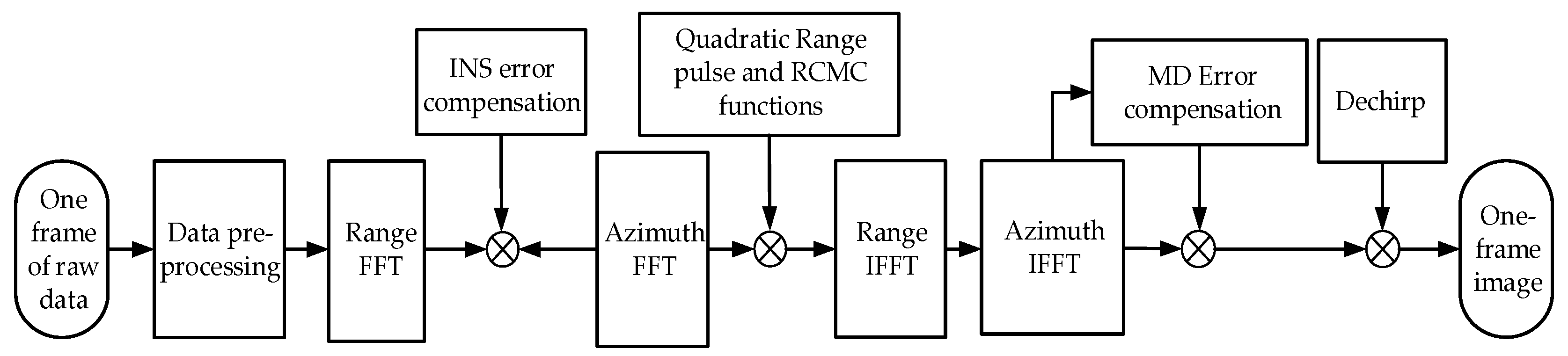
2.1. RD Algorithms
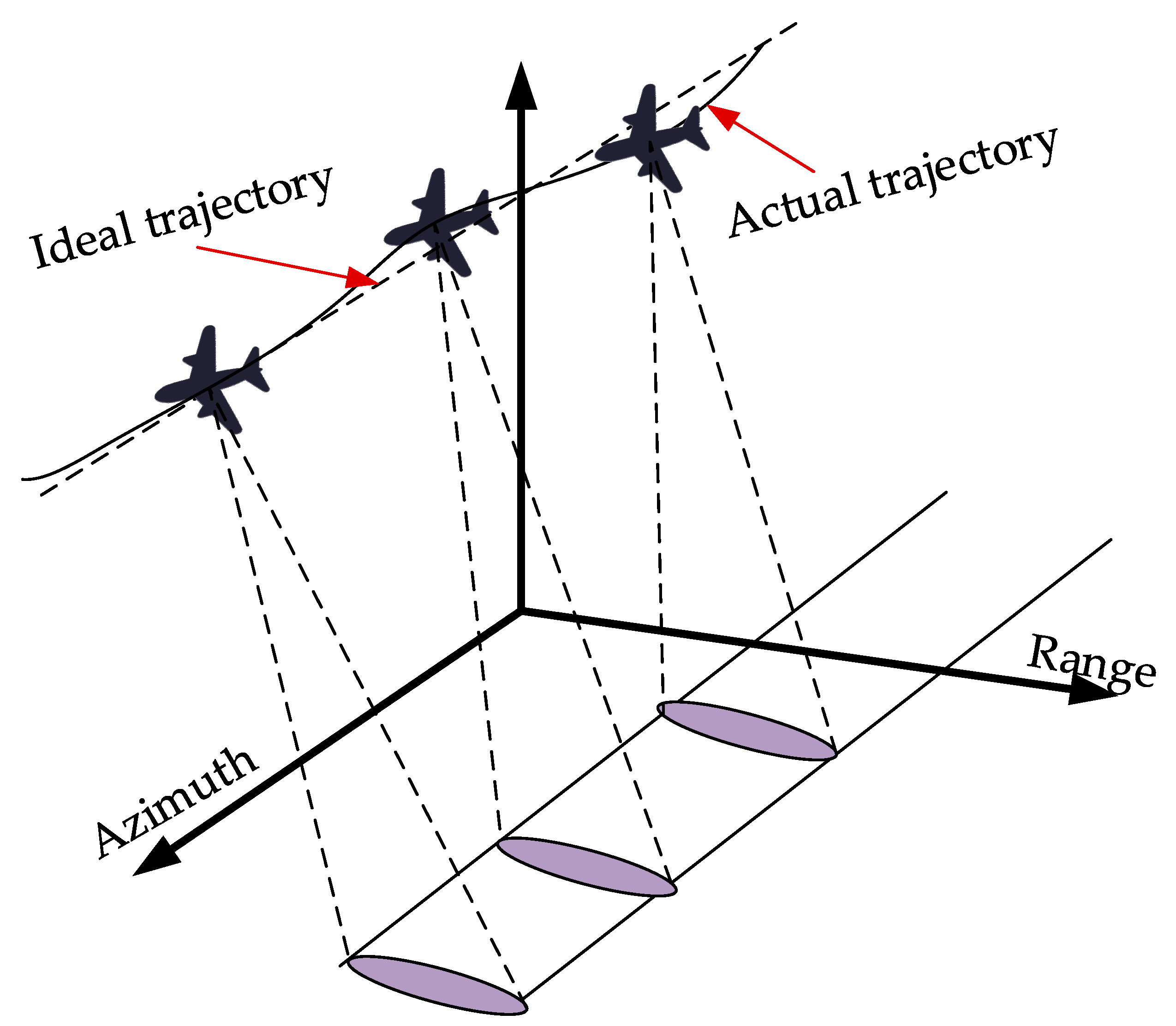
2.2. MD Algorithms
| Algorithm 1: Improved MD Algorithm. |
| Input: ; ; 1: for do 2: 3: 4: 5: 6: for do 7: 8: 9: end 10: 11: 12: 13: 14: 15: 16: 17: 18: 19: 20: end 20: 21: 22: 25: Output: |
3. Implementing MRIPC on FPGA
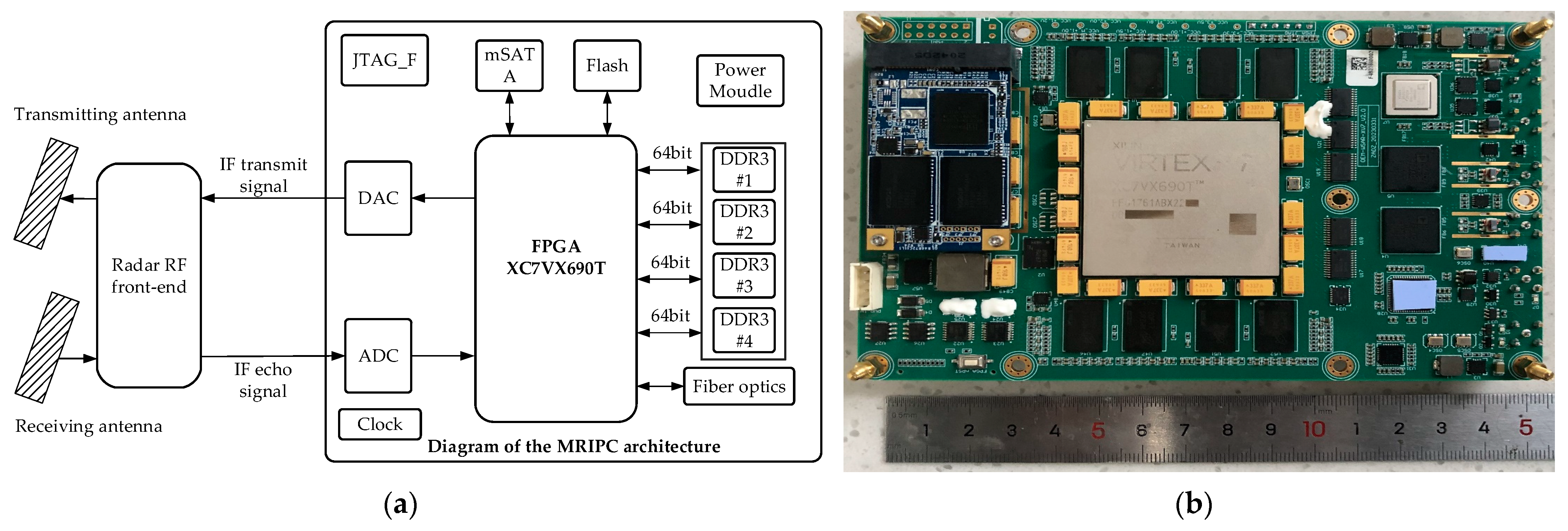
3.1. Designing MRIPC Components
3.2. Implementing High Frame Rate Real-Time Imaging Algorithms on FPGA
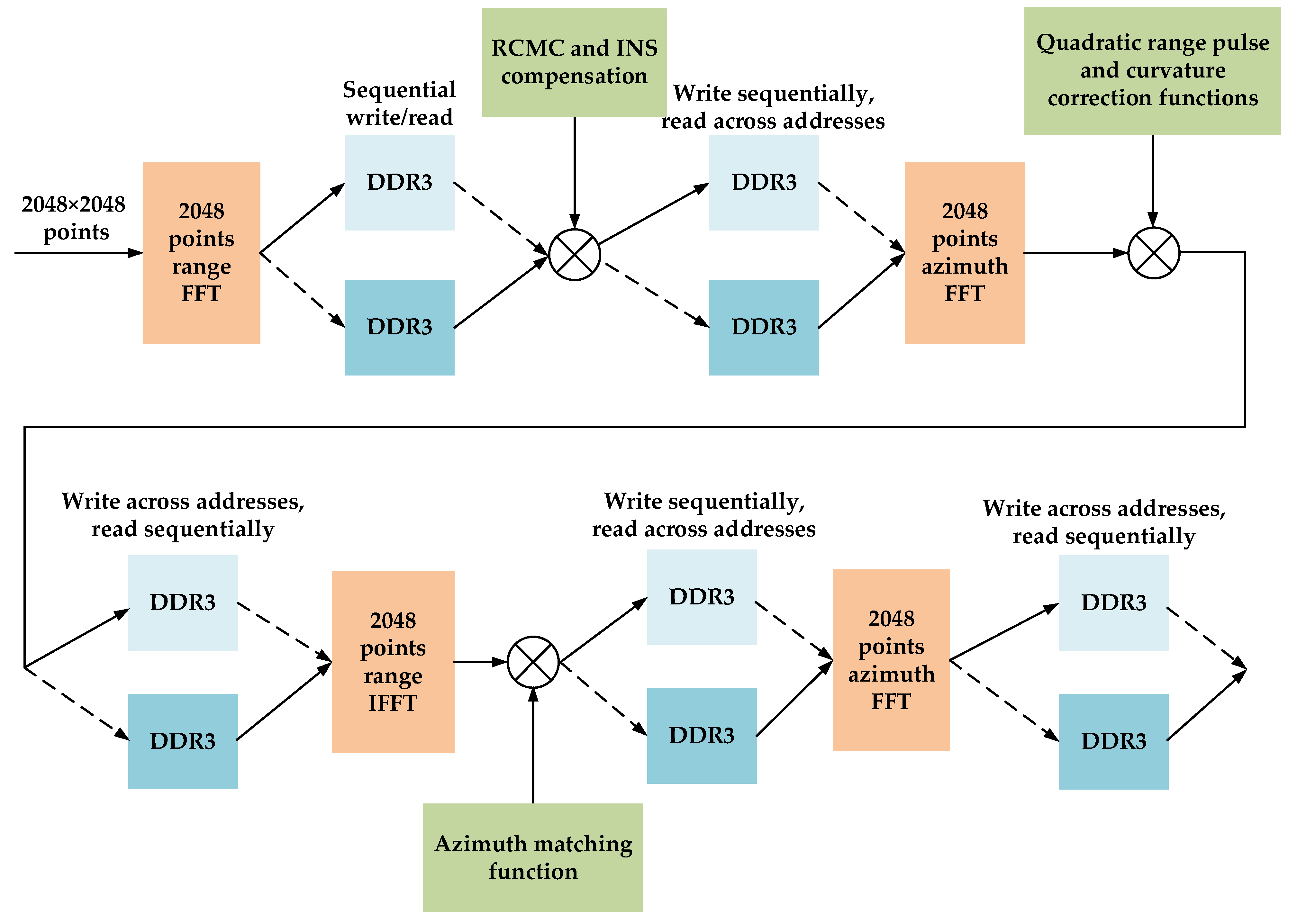
3.2.1. Implementing RD Algorithm on FPGA
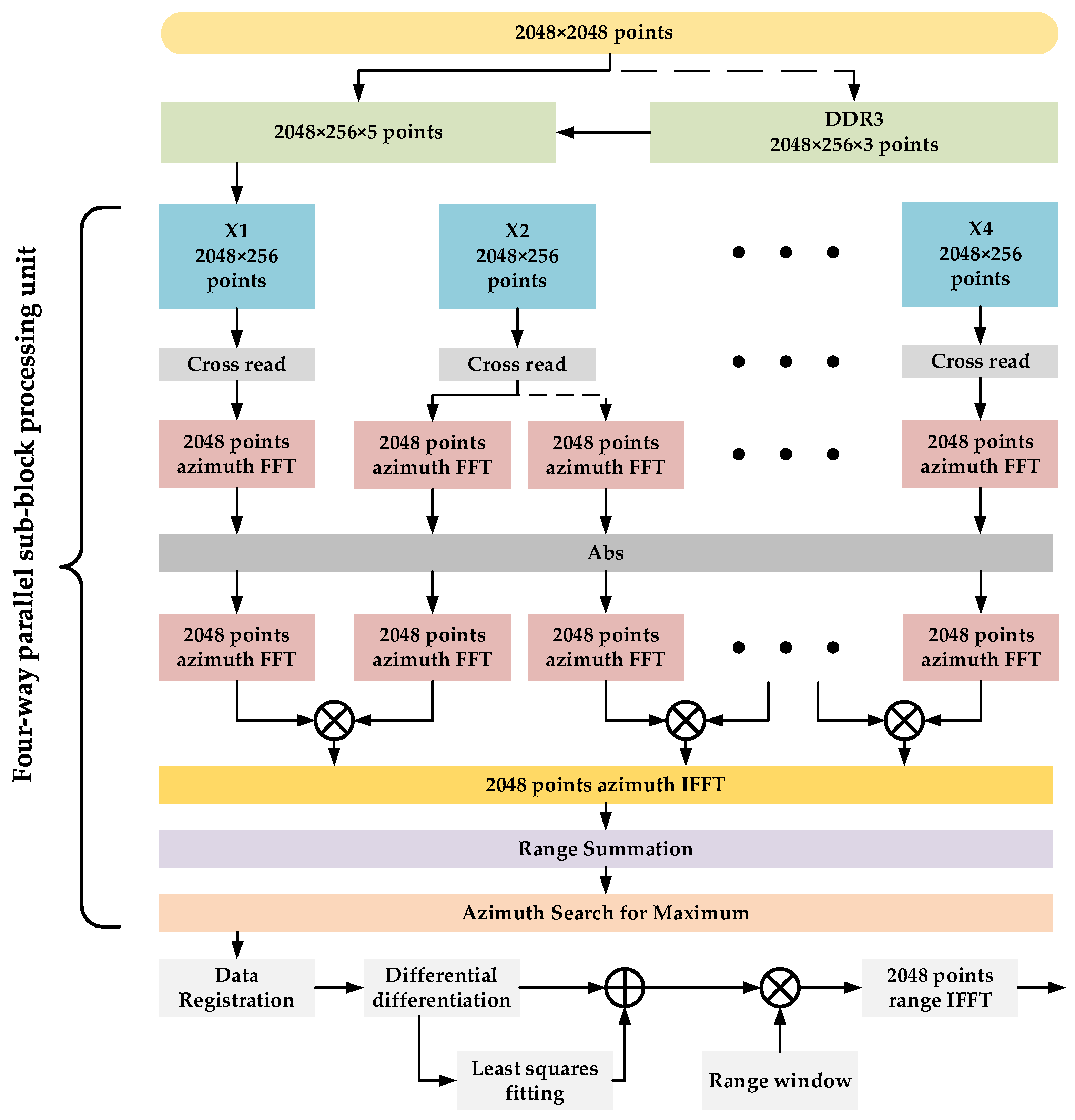
3.2.2. Implementing MD Algorithm on FPGA
4. Verification of MRIPC and Analysis
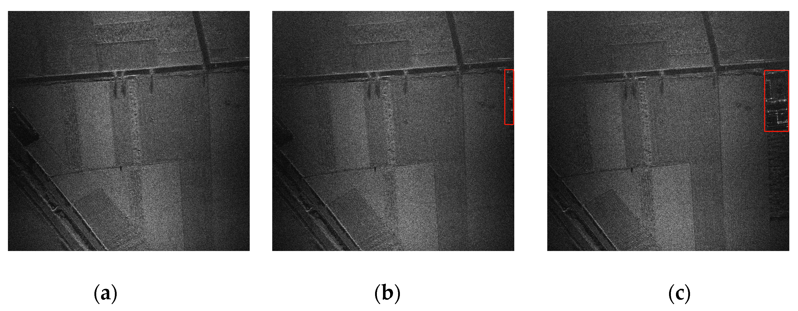
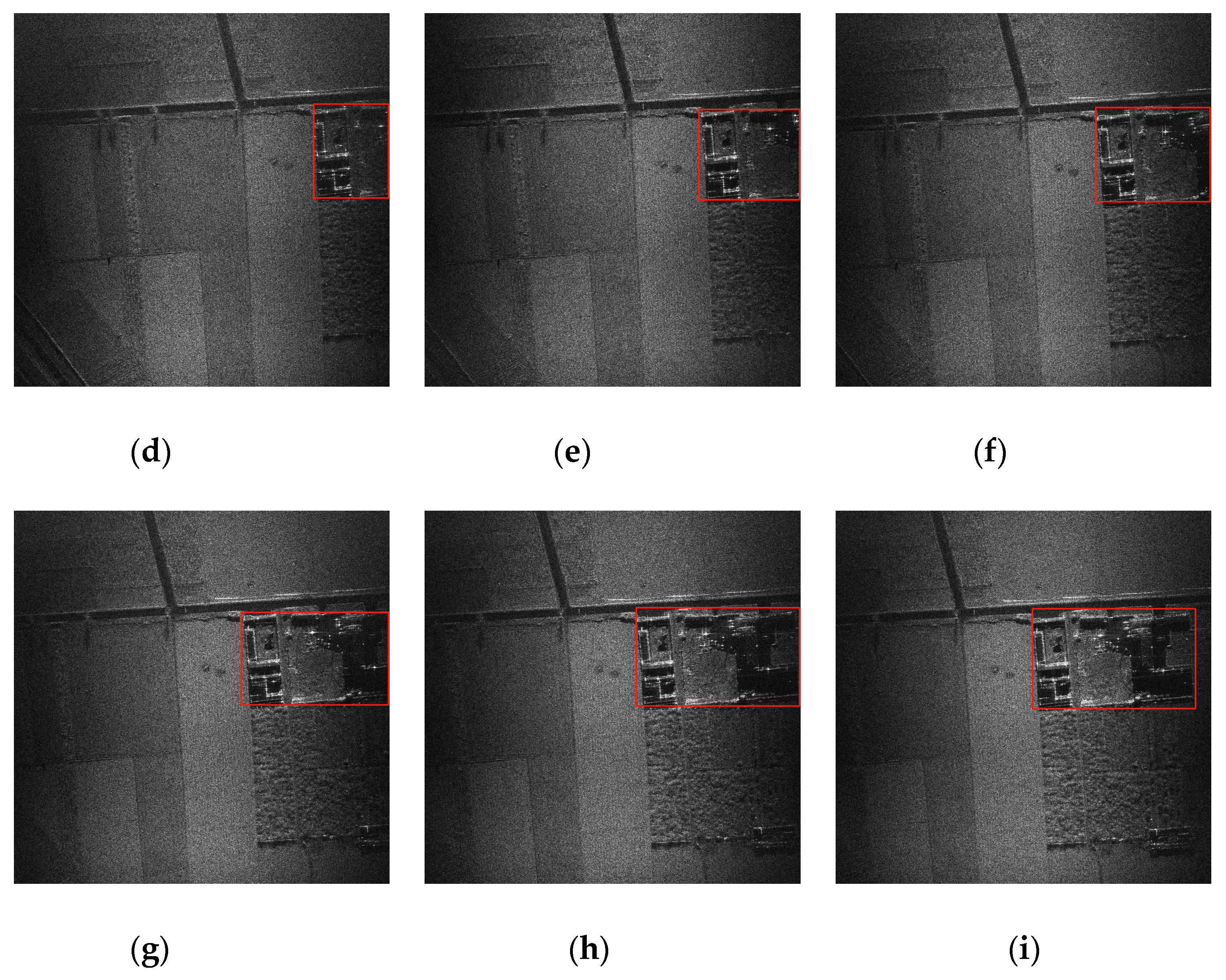
4.1. Processing Result of MRIPC
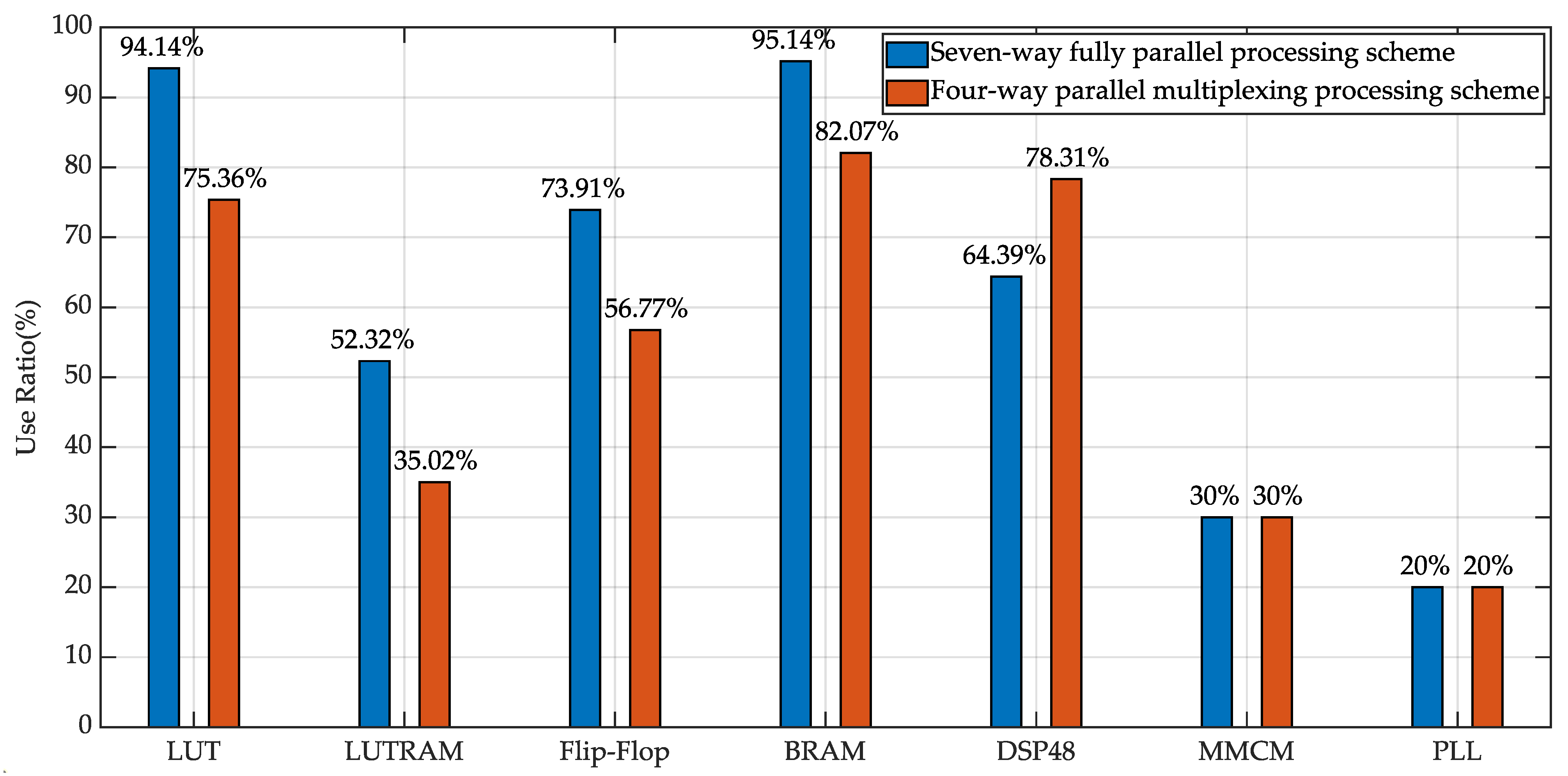
4.2. Processing Performance of MRIPC
5. Conclusions
Author Contributions
Funding
Data Availability Statement
Conflicts of Interest
References
- Cao, N.; Lee, H.; Zau, E. Estimation of Residual Motion Errors in Airborne SAR Interferometry Based on Time-Domain Back projection and Multisquint Techniques. IEEE Trans. Geosci. Remote Sens. 2018, 56, 2397–2407. [Google Scholar] [CrossRef]
- An, H.; Wu, J.; Teh, K.; Sun, Z.; Li, Z.; Yang, J. Joint Low-Rank and Sparse Tensors Recovery for Video Synthetic Aperture Radar Imaging. IEEE Trans. Geosci. Remote Sens. 2022, 60, 5214913. [Google Scholar] [CrossRef]
- Yan, H.; Liu, H.; Zhou, Y.; Cheng, L. A New Method of Video SAR Ground Moving Target Detection and Tracking Based on the Interframe Amplitude Temporal Curve. IEEE Trans. Geosci. Remote Sens. 2023, 61, 5219217. [Google Scholar] [CrossRef]
- Li, Z.; Qiu, X.; Yang, J.; Meng, D.; Huang, L.; Song, S. An Efficient BP Algorithm Based on TSU-ICSI Combined with GPU Parallel Computing. Remote Sens. 2023, 15, 5529. [Google Scholar] [CrossRef]
- A Edwards, M.; Madsen, D.; Stringham, C.; Margulis, A.; Wicks, B.; Long, D.G. microASAR: A small, Robust LFM-CW SAR for Operation on UAVs and Small Aircraft. In Proceedings of the 2008 IEEE International Geoscience and Remote Sensing Symposium (IGARSS), Boston, MA, USA, 7–11 July 2008; pp. 514–517. [Google Scholar] [CrossRef]
- MiniSAR. Available online: http://www.sandia.gov/radar/images/SAND.2014.8 (accessed on 4 November 2023).
- Halcrow, G.; Greig, D.W.; Glass, A. PicoSAR trials results. In Proceedings of the 2013 14th International Radar Symposium (IRS), Dresden, Germany, 19–21 June 2013; pp. 47–52. [Google Scholar]
- Wiehle, S.; Mandapati, S.; Günzel, D.; Breit, H.; Balss, U. Synthetic Aperture Radar Image Formation and Processing on an MPSoC. IEEE Trans. Geosci. Remote Sens. 2022, 60, 5226814. [Google Scholar] [CrossRef]
- Yang, L.; Zhao, L.; Zhou, S.; Bi, G.; Yang, H. Spectrum-Oriented FFBP Algorithm in Quasi-Polar Grid for SAR Imaging on Maneuvering Platform. IEEE Geosci. Remote Sens. Lett. 2017, 14, 724–728. [Google Scholar] [CrossRef]
- Li, Y.; Xu, G.; Zhou, S.; Xing, M.; Song, X. A Novel CFFBP Algorithm with Noninterpolation Image Merging for Bistatic Forward-Looking SAR Focusing. IEEE Trans. Geosci. Remote Sens. 2022, 60, 5225916. [Google Scholar] [CrossRef]
- Song, Y.; Hai, Y.; Wu, J.; Li, Z.; Yang, J. An Efficient PFA Sub aperture Algorithm for Video SAR Imaging. In Proceedings of the 2021 IEEE International Geoscience and Remote Sensing Symposium IGARSS, Brussels, Belgium, 11–16 July 2021; pp. 5179–5182. [Google Scholar] [CrossRef]
- Zhang, Q.; Wu, J.; Li, Z.; Miao, Y.; Huang, Y.; Yang, J. PFA for Bistatic Forward-Looking SAR Mounted on High-Speed Maneuvering Platforms. IEEE Trans. Geosci. Remote Sens. 2019, 57, 6018–6036. [Google Scholar] [CrossRef]
- Wang, Z.; Wei, F.; Huang, Y.; Zhang, X.; Zhang, Z. Improved RD imaging method based on the principle of step-by-step calculation. In Proceedings of the 2021 2nd China International SAR Symposium (CISS), Shanghai, China, 3–5 November 2021; pp. 1–5. [Google Scholar] [CrossRef]
- Gui, L.; Hai, Y.; Wu, J.; Li, Z.; Yang, J. A Motion Error Estimation Method of UWB-SAR Based on Coherent Correlation Function. In Proceedings of the 2022 IEEE International Geoscience and Remote Sensing Symposium (IGARSS), Kuala Lumpur, Malaysia, 17–22 July 2022; pp. 2083–2086. [Google Scholar] [CrossRef]
- Chen, J.; An, D.; Wang, W.; Chen, L.; Feng, D.; Zhou, Z. A Novel Generation Method of High Quality Video Image for High Resolution Airborne ViSAR. Remote Sens. 2021, 13, 3706. [Google Scholar] [CrossRef]
- Chen, J.; Li, M.; Yu, H.; Xing, M. Full-Aperture Processing of Airborne Microwave Photonic SAR Raw Data. IEEE Trans. Geosci. Remote Sens. 2023, 61, 1–12. [Google Scholar] [CrossRef]
- Wang, T.; Zhu, D.; Meng, X. Implementation of Terahertz Video SAR Imaging Based on Multi-Core DSP. In Proceedings of the 2022 7th International Conference on Signal and Image Processing (ICSIP), Suzhou, China, 20–22 July 2022; pp. 541–545. [Google Scholar] [CrossRef]
- Zhang, Y.; Zhou, J.; Song, Z.; Zhou, K. High-Precision GPU-Accelerated Simulation Algorithm for Targets under Non-Uniform Cluttered Backgrounds. Remote Sens. 2023, 15, 4664. [Google Scholar] [CrossRef]
- Tian, H.; Hua, W.; Gao, Y.; Sun, Z.; Cai, M.; Guo, Y. Research on Real-time Imaging Method of Airborne SAR Based on Embedded GPU. In Proceedings of the 2022 3rd China International SAR Symposium (CISS), Shanghai, China, 2–4 November 2022; pp. 1–4. [Google Scholar] [CrossRef]
- Yang, T.; Xu, Q.; Meng, F.; Zhang, S. Distributed Real-Time Image Processing of Formation Flying SAR Based on Embedded GPUs. IEEE J. Sel. Top. Appl. Earth Obs. Remote Sens. 2022, 15, 6495–6505. [Google Scholar] [CrossRef]
- Cai, M.; Wang, H.; Hua, W. Research on Optimal Design of Spaceborne SAR Real-time Imaging Technology Based on FPGA. In Proceedings of the 2021 2nd China International SAR Symposium (CISS), Shanghai, China, 3–5 November 2021; pp. 1–2. [Google Scholar] [CrossRef]
- Hettiarachchi, D.L.N.; Balster, J.E. Fixed-Point Processing of the SAR Back-Projection Algorithm on FPGA. IEEE J. Sel. Top. Appl. Earth Obs. Remote Sens. 2021, 14, 10889–10902. [Google Scholar] [CrossRef]
- Tong, W.; Wei, B.; Yu, A.; Dong, Z.; He, Z.; Tang, F. Video SAR Moving Target Detection System Based on FPGA. In Proceedings of the 2023 8th International Conference on Signal and Image Processing (ICSIP), Wuxi, China, 8–10 July 2023; pp. 419–423. [Google Scholar] [CrossRef]
- Choi, Y.; Jeong, D.; Lee, M.; Lee, W.; Jung, Y. FPGA Implementation of the Range-Doppler Algorithm for Real-Time Synthetic Aperture Radar Imaging. Electronics 2021, 10, 2133. [Google Scholar] [CrossRef]
- Mota, D.; Cruz, H.; Miranda, P.R.; Duarte, R.P. Onboard Processing of Synthetic Aperture Radar Back-projection Algorithm in FPGA. IEEE J. Sel. Top. Appl. Earth Obs. Remote Sens. 2022, 15, 3600–3611. [Google Scholar] [CrossRef]
- Chen, J.; Liang, B.; Zhang, J.; Yang, G.D. Efficiency and Robustness Improvement of Airborne SAR Motion Compensation with High Resolution and Wide Swath. IEEE Geosci. Remote Sens. Lett. 2022, 19, 4004005. [Google Scholar] [CrossRef]
- Li, C.; Zhang, H.; Deng, Y.; Wang, R. Focusing the L-Band Spaceborne Bistatic SAR MissionData Using a Modified RD Algorithm. IEEE Trans. Geosci. Remote Sens. 2020, 58, 294–306. [Google Scholar] [CrossRef]
- Jin, Y.; Chen, J.; Xia, X.G. Ultrahigh-Resolution Autofocusing for Squint Airborne SAR Basedon Cascaded MD-PGA. IEEE Geosci. Remote Sens. Lett. 2022, 19, 4017305. [Google Scholar] [CrossRef]
- Tang, Y.; Zhang, B.; Xing, M.; Bao, Z.; Guo, L. The Space-Variant Phase-Error Matching Map-Drift Algorithm for Highly Squinted SAR. IEEE Geosci. Remote Sens. Lett. 2013, 10, 845–849. [Google Scholar] [CrossRef]
- Cao, Y.; Guo, S.; Jiang, S.; Zhou, X.; Wang, X.; Luo, Y.; Yu, Z.; Zhang, Z.; Deng, Y. Parallel Optimisation and Implementation of a Real-Time Back Projection (BP) Algorithm for SAR Based on FPGA. Sensors 2022, 22, 2292. [Google Scholar] [CrossRef]
- Lee, J.; Jeong, D.; Lee, S.; Lee, M.; Lee, W.; Jung, Y. FPGA Implementation of the Chirp-Scaling Algorithm for Real-Time Synthetic Aperture Radar Imaging. Sensors 2023, 23, 959. [Google Scholar] [CrossRef] [PubMed]
- Yang, T.; Zhang, X.; Xu, Q.; Zhang, S.; Wang, T. An Embedded GPU-Based Scheme for Real-Time Imaging Processing of Unmanned Aerial Vehicle Borne Video Synthetic Aperture Radar. Remote Sens. 2024, 16, 191. [Google Scholar] [CrossRef]


| Work | Platform | Image Size | Algorithm | Time (s) | Operating Frequency | Imaging Quality |
|---|---|---|---|---|---|---|
| [30] | Xilinx XC7VX690T | 900 × 900 | BP | 1.10 s | 200 MHz | PSNR = 27.26 dB SSIM = 0.8652 |
| [31] | Xilinx Zynq UltraScale + FPFA | 2048 × 2048 | CS | 0.48 s | 235 MHz | PSNR = 33.43 dB SSIM = 0.947 |
| [32] | Jetson AGX Orin | 2048 × 2048 | RD + MD | 0.135 s | 1.30 GHz | PSNR = 48.1308 dB SSIM = 0.9652 |
| Ours | Xilinx XC7VX690T | 2048 × 2048 | RD + MD | 0.20 s | 200 MHz | PSNR = 37.64 dB SSIM = 0.954 |
Disclaimer/Publisher’s Note: The statements, opinions and data contained in all publications are solely those of the individual author(s) and contributor(s) and not of MDPI and/or the editor(s). MDPI and/or the editor(s) disclaim responsibility for any injury to people or property resulting from any ideas, methods, instructions or products referred to in the content. |
© 2024 by the authors. Licensee MDPI, Basel, Switzerland. This article is an open access article distributed under the terms and conditions of the Creative Commons Attribution (CC BY) license (https://creativecommons.org/licenses/by/4.0/).
Share and Cite
Yang, T.; Wang, T.; Zheng, N.; Zhang, S.; Meng, F.; Zhang, X.; Wu, Q. Miniaturization Design of High-Integration Unmanned Aerial Vehicle-Borne Video Synthetic Aperture Radar Real-Time Imaging Processing Component. Remote Sens. 2024, 16, 1273. https://doi.org/10.3390/rs16071273
Yang T, Wang T, Zheng N, Zhang S, Meng F, Zhang X, Wu Q. Miniaturization Design of High-Integration Unmanned Aerial Vehicle-Borne Video Synthetic Aperture Radar Real-Time Imaging Processing Component. Remote Sensing. 2024; 16(7):1273. https://doi.org/10.3390/rs16071273
Chicago/Turabian StyleYang, Tao, Tong Wang, Nannan Zheng, Shuangxi Zhang, Fanteng Meng, Xinyu Zhang, and Qirui Wu. 2024. "Miniaturization Design of High-Integration Unmanned Aerial Vehicle-Borne Video Synthetic Aperture Radar Real-Time Imaging Processing Component" Remote Sensing 16, no. 7: 1273. https://doi.org/10.3390/rs16071273