1. Introduction
Synthetic Aperture Radar (SAR) is a remote sensing technology that uses high-frequency electromagnetic waves to emit and receive echoes from the earth’s surface to obtain surface information [
1]. Unlike optical remote sensing, SAR sensors can collect data under any weather conditions because they acquire target information by transmitting electromagnetic waves, independent of weather conditions [
2,
3]. Because of various error factors such as range measurement, Doppler center frequency, satellite ephemeris, and satellite attitude measurement accuracy during SAR satellite imaging, geometric features of various land features in SAR satellite images, including size, shape, and orientation, can be distorted. SAR satellite image ortho-rectification is based on the geometric positioning model of SAR satellites. It processes the geometric errors caused by various factors such as satellite platform, SAR payload, and terrain undulation based on high-precision control point data and elevation data, resulting in SAR satellite image ortho-rectification products with geographic coding and conforming to orthographic projection.
Currently, there are two main types of positioning methods for SAR satellite images as follows: methods based on rigorous models and methods based on generic models [
4,
5]. For SAR images, the rigorous model is the range-Doppler (RD) model, which mainly discusses the relationship between image points and target points from the perspective of synthetic aperture radar imaging geometry. It was first proposed by Brown in 1981 [
6]. Based on this model, Curlander further studied the positioning method based on the RD model and achieved the precise positioning of SAR images by solving the Doppler equation [
7]. With the launch of SAR systems such as TerraSAR-X, German Aerospace developed software for SAR image geocoding, which realized fast processing of SAR images based on the RD model [
8]. With the expansion of SAR image applications, extensive research has been conducted on the positioning of SAR images both domestically and internationally. Zhang et al. proposed a method to solve the RD imaging equation without ground control points. By using the slant range vector in the RD equation as a variable and expanding the error equation through Taylor series expansion, the position information of the target point was iteratively solved using the least squares adjustment principle [
9]. Chen et al. proposed a method that combines analytical and numerical solution algorithms for the direct positioning of SAR images on board satellites [
10]. Li et al. proposed research on the positioning method of SAR images based on satellite parameter prediction [
11]. However, because of the requirement of precise orbital parameters at the moment of satellite imaging for the RD model and the different formats of SAR satellite parameters, the joint processing of multi-source SAR images is greatly limited.
Therefore, in order to adapt to the joint processing of multi-source remote sensing image data, generic positioning models emerged, among which the most widely used is the Rational Function Model (RFM) [
12,
13,
14,
15]. RFM uses a rational polynomial form to fit the rigorous model and was initially used for the geolocation of optical images [
16,
17,
18]. With continuous research by scientists, RFM began to be gradually applied to the geolocation of SAR images [
19,
20,
21]. Zhang et al. proposed a method to replace the rigorous model with the RFM model for SAR image geolocation and experimentally verified the effectiveness of the RFM model [
22]. He et al. proposed a hybrid method that combines the L curve and IMCCV (iterative method to modify the characteristic values) to solve the unconditional equations in the rational polynomial coefficients (RPCs) model [
23]. Subsequently, Zhang et al. introduced the RFM model into the InSAR processing technology and constructed SAR and InSAR data processing models based on RFM [
24]. Zhao et al. proposed a method for calculating the geometric angles of SAR local imaging based on the RFM model [
25]. Liu proposed a real-time geometric correction method and system for SAR images based on RD plane pixel mapping, which deduces the ground distance coordinates of each pixel of real-time SAR imaging results through imaging geometry relationships. At the same time, in the process of pixel-grid positioning, the ground distance pixel scale adjustment is realized using the ground distance coordinate [
26].
During the process of the ortho-rectification of remote sensing images, whether it is a rigorous model or an RFM model, point-by-point interpolation calculations are required. At the same time, because of the large range of remote sensing images, parallel point-by-point interpolation calculations consume a lot of processing time. In order to improve computational efficiency, scholars have conducted relevant research on parallel ortho-rectification methods for remote sensing image processing. Fang et al. addressed the problem of long processing time for the ortho-rectification of high-resolution, large-swath optical satellite images and proposed a CPU-GPU collaborative processing strategy for the ortho-rectification of optical satellite remote sensing images to fully utilize the computational performance of the CPU-GPU collaborative processing architecture [
27]. Based on this, Wang et al. proposed a GPU block acceleration strategy for the ortho-rectification processing of remote sensing images [
28]. Xiao et al. proposed a hierarchical logical strategy for the ortho-rectification processing of high swath width GaoFen-4 remote sensing images, which is suitable for large-area remote sensing image ortho-rectification processing to improve efficiency [
29]. However, because of special phenomena such as layover, shadow, and perspective shrinkage in SAR images, traditional ortho-rectification strategies for optical images cannot fully meet the requirements of SAR image ortho-rectification. Therefore, this paper proposes a multi-GPU acceleration strategy for SAR images in large areas. Based on the pixel-to-object ortho-rectification method based on SAR geometric characteristics, the block strategy for SAR image ortho-rectification is optimized according to the resource conditions of different GPU nodes, thereby optimizing the efficiency of SAR image ortho-rectification.
For the time-consuming pixel-by-pixel operation in SAR satellite image ortho-rectification, this paper proposes a GPU pixel-by-pixel rectification method for SAR images based on the RPC rational function model, which improves the processing efficiency of SAR satellite image ortho-rectification. Based on this, aiming at the problem of linearly increasing time consumption in the ortho-rectification processing of multiple SAR images in large-area mosaicking of SAR satellite images, this paper further proposes a multi-GPU collaborative acceleration strategy for the ortho-rectification of multiple SAR images in large areas. Finally, efficient ortho-rectification processing of multiple SAR image data in large areas is achieved.
This paper conducts research in the following five parts:
Section 1 briefly analyzes the problems to be solved in SAR satellite image ortho-rectification and the reasons for GPU acceleration.
Section 2 introduces the two geometric positioning models for SAR satellite image ortho-rectification.
Section 3 proposes a pixel-to-object ortho-rectification method based on SAR geometric characteristics and a SAR ortho-rectification model based on pixel-to-object imaging.
Section 4 uses 20 scenes of Gaofen-3 SAR images to carry out ortho-rectification experiments and analyzes the experimental results.
Section 5 verifies the feasibility and efficiency of the GPU-accelerated processing method for the ortho-rectification of SAR satellite images through experiments.
2. SAR Satellite Image Ortho-Rectification Model
Compared with optical imaging, SAR systems use active transmission and reception of signals for imaging, which is fundamentally different from passive optical imaging. Therefore, there are significant differences between SAR images and optical images in imaging principles, geometric structures, and radiation characteristics, making it difficult to directly apply conventional calibration methods (e.g., inverse methods) for optical images to SAR image correction. Instead, a forward method is used to correct the SAR slant range image pixel by pixel to obtain the final orthorectified image. The two main geometric positioning models for SAR imagery are based on the rigorous imaging model and the general imaging model.
2.1. Ortho-Rectification Model Based on Rigorous Imaging
The ortho-rectification model of SAR satellite images based on rigorous imaging is the range-Doppler positioning model.
Range measurement and Doppler frequency measurement are the two major measurements in SAR, which decompose the object into two-dimensional components in the range and azimuth directions through distance measurement and Doppler frequency measurement. This is achieved by measuring the time delay (range measurement) of the radar pulse propagation between the radar and the object to decompose the object in the radar line-of-sight (range direction). The azimuth position of the object is determined by measuring the Doppler frequency shift.
Based on the principles of slant range measurement and Doppler, a positioning method that conforms to the SAR imaging mechanism can be obtained. Within a range scan line, any point on the slant range image should satisfy the slant range distance condition and the Doppler condition specified in Equation (1):
The ground point also satisfies the ellipsoid equation in Equation (2):
where
is the image coordinate (column) corresponding to the ground point coordinates
,
is the near-range slant range,
is the wavelength of the radar,
is the resolution in the slant range direction, which is generally known,
is the Doppler center frequency value, which can be accurately calculated during image processing and is also known,
and
are the three-dimensional position and velocity of the satellite,
and
are the long and short semi-axes of the earth reference ellipsoid, and
is the height of the ground point.
The georeferencing of SAR images based on range and Doppler primarily involves the design of orbital position parameters and the establishment of range-Doppler equations. For simplicity, the satellite platform operating at high altitude can be considered to have a stable operation. Its position changes can be accurately described using acceleration, velocity, and position state variables. According to Newtonian mechanics, it is known that the satellite position and velocity at any time are given by:
where
is closely related to the scan line and can be expressed as
, where
is the row coordinate of the image and
is the pulse repetition frequency of the SAR, which is a known constant.
2.2. Ortho-Rectification Model Based on General Imaging
For satellite remote sensing images, because of stable satellite flight, slow attitude changes, and nearly parallel projection during imaging, there is a strong correlation between the various orientation elements of the image, making it difficult to control the numerical stability of the bundle adjustment method based on the strict imaging geometry model during the solution process, even though it is theoretically rigorous. At the same time, because of technical confidentiality and other factors, the imaging mode and orbit information of the satellite are not publicly available, making it difficult to establish a strict geometric imaging model for the sensor. Unlike the strict sensor model, the RPC model does not require knowledge of the physical properties of each type of imaging sensor, such as orbit parameters and platform orientation parameters. Therefore, for high-resolution optical satellite images, the RPC model based on single-scene image has been widely used in recent years.
Zhang et al. [
16] verified the substitutability of the RPC model for the rigorous imaging model of SAR from both theoretical and experimental aspects, demonstrating the feasibility of using the RPC model to fit SAR image imaging. The experimental results showed that the RPC model can achieve high fitting accuracy for SAR systems of different resolutions and can be used for the photogrammetric processing of SAR images.
Currently, in the field of optical remote sensing, the RFM has become a standard and is supported by many commercial software programs. Research has also been carried out on methods for stereomapping based on the RFM model, and the same model can be used for georeferencing SAR images.
The RFM model represents the image coordinates
as a polynomial ratio with respect to the corresponding ground spatial coordinates
:
where
,
,
, and
are polynomials with respect to
. When the control points used to solve the RFM parameters are unevenly distributed or the model is overly parameterized, the denominators in the model can change drastically, resulting in the normal equations of the error equations being severely ill-conditioned after linearization. To reduce numerical errors in calculations, the image coordinates and geographical coordinates are normalized:
where
are the normalized translation parameters and
are the normalized scaling parameters. The normalized coordinates
and
represent the normalized image coordinates and geographical coordinates, respectively. This normalization process reduces rounding errors introduced because of the difference in data scales.
Each term in the polynomial has a maximum degree of 3 for the coordinates
, and the total degree of all terms in each polynomial does not exceed 3. The form of each polynomial is as follows:
where
) are rational function coefficients. In most cases,
b0 and
e0 are both equal to 1, so the core parameters of RFM are the rational polynomial coefficients, often referred to as RPC.
3. Methods
3.1. Geometric Correction Method for SAR Images Based on the Image-to-Ground Ortho-Rectification Process
Because of the imaging characteristics of SAR, when the echoes of multiple positions reflected by the target reach the radar antenna at the same distance, they will appear at the same position on the SAR image. This phenomenon forms an area in the image called the layover region. In the layover region, traditional correction methods may cause “smearing” effects in the corrected image. These phenomena can have different degrees of impact on target structures, posing challenges to the accurate interpretation of high-resolution SAR images and limiting their use in various applications. Therefore, an image-to-ground ortho-rectification method based on the geometric characteristics of SAR can provide precise correction of SAR images by combining the elevation data provided by the digital surface model (DSM) to calculate the ground coordinates after correction for each pixel.
In the SAR image ortho-rectification model, the pixels in the non-layover region can directly calculate the accurate position coordinates in the ground space based on the single mapping relationship between the image space and the ground space. The processing flow is as follows:
- (1)
According to the SAR range Doppler localization model parameters and the iteration calculation of the ground coordinates , obtain the ground latitude and longitude coordinates .
- (2)
Based on the latitude and longitude coordinates, compute the corresponding elevation value on the DSM.
- (3)
Calculate the elevation change . If , exit the loop, and the corresponding latitude and longitude coordinates of the pixel coordinates are obtained. If the above requirement is not met, set , and then repeat steps (1)–(3) until the condition for exiting the loop is met or the maximum number of iterations is reached and the iteration does not converge, and force an exit.
According to the above processing flow, the ground latitude and longitude coordinate information corresponding to the pixels in the non-layover region can be obtained. For the pixels in the layover region, since their pixel coordinates correspond to multiple ground space coordinates, it is necessary to solve the corresponding ground space coordinates of the target structure to resolve the mixed pixel information. Assuming that the image-to-ground coordinates of the region to be corrected are , with the initial elevation of the center of the region , the following correction model based on SAR geometric characteristics is applied:
- (1)
Based on the SAR range Doppler localization model parameters and the iteration calculation of the image-to-ground coordinates , obtain the ground latitude and longitude coordinates .
- (2)
Set the elevation change range . For each elevation value in the elevation change range, use the SAR range Doppler localization model to iteratively calculate the latitude and longitude coordinates corresponding to , and obtain the elevation value on the DSM based on the latitude and longitude coordinates.
- (3)
By traversing all the elevation values in the elevation change range, obtain the elevation linear change curve and the DSM elevation curve . Calculate the intersection between the two elevation curves as the multiple ground space coordinates corresponding to the pixel coordinates.
- (4)
Considering that higher targets always occlude lower targets when an image is occluded, take the ground space coordinates corresponding to the highest elevation value in the intersection as the final orthorectified coordinates.
According to the above steps, the ground coordinates corresponding to each pixel coordinate of the SAR-corrected image can be obtained. Then, based on the radiation values corresponding to the pixel coordinates, gray value interpolation can be applied to the ground coordinates to obtain the final orthorectified image.
3.2. GPU-Accelerated Processing Method Based on the Image-to-Ground SAR Ortho-Rectification Model
SAR image data needs to be orthorectified before further processing such as mosaic and radiometric normalization. For large-area SAR image data, considering the iterative processing required by the ortho-rectification model based on SAR geometric characteristics, it is necessary to design targeted acceleration algorithms to improve the efficiency of ortho-rectification processing. Currently, there are two main problems in ortho-rectification of large-area SAR images as follows:
- (1)
Ortho-rectification requires pixel-by-pixel computation, which is time-consuming. Furthermore, for large-area SAR image data consisting of multiple images, the processing time for ortho-rectification increases linearly, requiring the proper allocation of multiple GPU nodes to accelerate the processing.
- (2)
The efficiency of ortho-rectification for non-layover pixels and layover pixels based on SAR geometric characteristics is different. The iteration for non-layover pixels generally converges in 3–5 iterations, making the computation efficient. However, handling layover pixels requires traversing all possible cases in the elevation change range, leading to lower efficiency. Usually, non-layover pixels are located in flat areas with small variations, while layover pixels are in areas with significant terrain variations. Therefore, GPU nodes and memory need to be allocated according to different types of SAR images.
To address the above problems, this study proposes a GPU-accelerated processing strategy based on the SAR geometric ortho-rectification model. To ensure generality, the RPC model is used instead of the range-Doppler geometric localization model. The RPC rational function model relates the ground coordinates () and the corresponding image coordinates () using ratio polynomials.
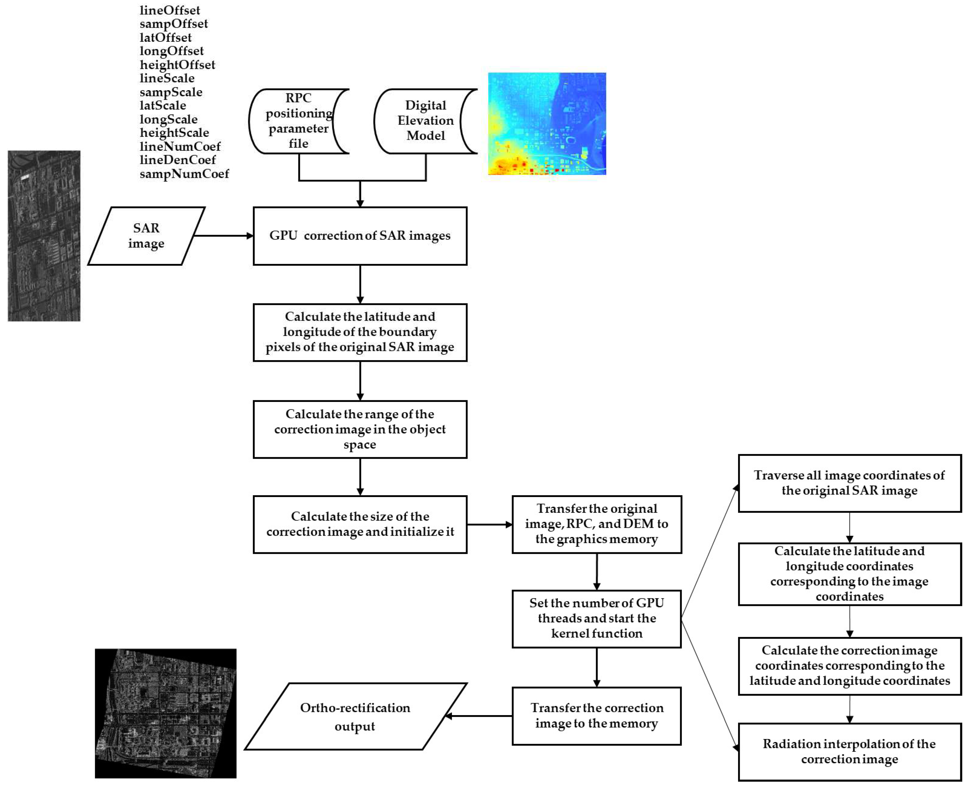
The steps for pixel-by-pixel ortho-rectification of SAR images using the RPC rational function model are as follows:
- (1)
According to the RPC rational function model, calculate the ground latitude and longitude coordinates of the boundary pixels of the original SAR image and the average elevation at the center of the image. Iterate to obtain the range of ground coordinates in the orthorectified image by calculating the maximum and minimum longitudes and latitudes.
- (2)
Based on the set ortho-rectification resolution and ground coordinate range, calculate the pixel size of the orthorectified image and initialize the image matrix file.
- (3)
Copy the RPC rational function model parameters, DEM elevation data, original SAR image data, and the initialized image matrix from memory to GPU memory. Initialize the number of parallel computing threads and blocks on the GPU.
- (4)
Use each GPU thread to iterate over the pixels of the original image and calculate the ground coordinates corresponding to the pixel coordinates based on the SAR geometric ortho-rectification model.
- (5)
Calculate the corresponding pixel coordinates in the orthorectified image based on the ground coordinates and perform interpolation on the radiometric values of the orthorectified image.
The overall processing flow is shown in
Figure 1.
- 2.
SAR Geometric Ortho-Rectification and Standardization Processing Based on Multi-GPU Collaboration
Multi-GPU nodes have the capability to simultaneously perform parallel ortho-rectification on multiple SAR images. Considering that SAR images have different sizes and land cover types, and the computation time for overlay and non-overlay pixels in a single SAR image also varies, the time required for the ortho-rectification of each SAR image is also different. Therefore, designing an appropriate strategy for distributing multiple GPU nodes is needed.
First, the optimal pixel size for processing is calculated based on the maximum memory limit of each GPU card. Then, the overlay pixel mask is calculated for the SAR images to be rectified. Based on the definition of overlay regions, the corresponding latitude and longitude coordinates in the object space are obtained. Therefore, the number of times the pixel coordinates obtained through the projection of latitude and longitude coordinates are traversed can be statistically counted. The coordinates that appear more than or equal to twice are considered overlay pixels, and a threshold segmentation based on the number of coordinates can be used to obtain the overlay pixels mask and calculate the overlay pixel ratio .
From the analysis of the processing models of non-overlay pixels and overlay pixels in the SAR geometric ortho-rectification model, it can be seen that the computation complexity of overlay pixels is determined by the traversal of the elevation space. Assuming the number of traversals in the elevation space is
, the computation amount of overlay pixels is
times that of non-overlay pixels. Based on the above analysis, the overlay pixel ratio of all SAR images to be rectified can be calculated first, and then the adjustment of the optimal size can be performed using the following formula:
where
and
are the adjusted optimal sizes based on the topography,
and
are the original processing sizes calculated based on the memory limit, and
is the overlay pixel ratio.
For SAR images with a low overlay pixel ratio, the processing efficiency is relatively fast, so a larger processing size can be set. For SAR images with a high overlay pixel ratio, the processing efficiency is relatively slow. In order to maintain the consistency of multi-GPU collaboration, a corresponding smaller size is set to ensure consistent processing time for different areas.
4. Experiment and Analysis
4.1. Experimental Data and Platform
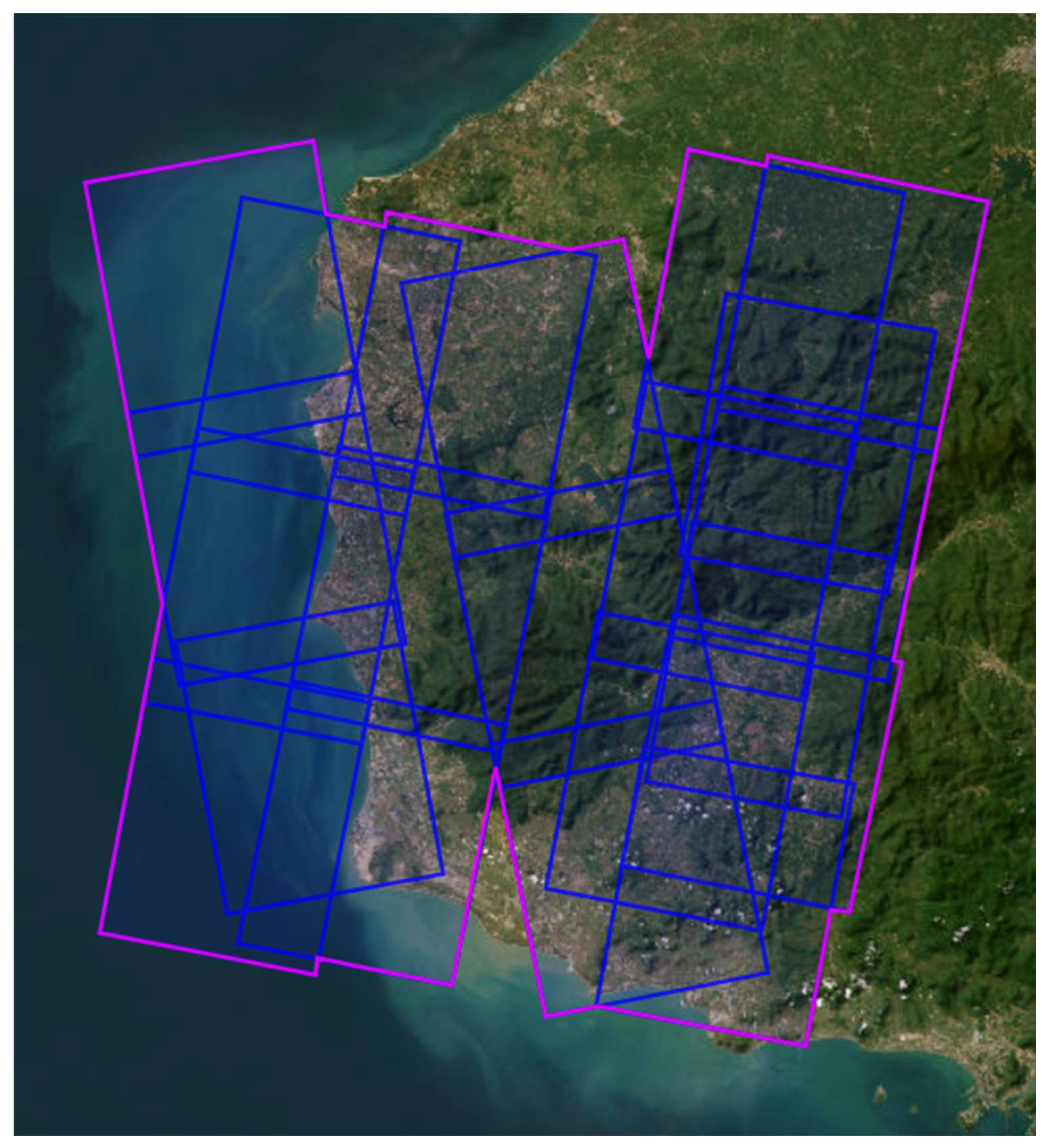
To verify the effectiveness of the proposed algorithm in this paper, validation experiments were conducted using domestic Gaofen-3 SAR satellite images. The Gaofen-3 SAR images used in the experiments were acquired in ultra-fine strip (UFS) mode, with a total of 20 images and a resolution of 3 m. The coverage area of the data used in the experiment is the southeastern coastal area of China, as shown in
Figure 2. The terrain elevation ranges from 0 m to 1500 m. The specific experimental data information is shown in
Table 1.
In the experiment, a high-performance computing server with specific hardware parameters, as shown in
Table 2, was used.
4.2. Experimental Process
To verify the effectiveness of the SAR image GPU-based per-pixel correction based on the RPC rational function model, and the SAR geometric ortho-rectification standardization processing based on multi-GPU cooperation, experiments were conducted with 20 scenes of Gaofen-3 SAR images acquired in UFS mode. Four experiments were conducted as follows:
- (1)
Implementation of geometric ortho-rectification algorithm on a single CPU server node
Using one CPU server node (without GPU card) consistent with the subsequent experimental server node configuration, an experiment was conducted to implement the CPU-based geometric ortho-rectification algorithm. The time for the ortho-rectification of the 20 scenes of Gaofen-3 SAR images in UFS mode was recorded as the baseline algorithm for comparison with the proposed GPU-based per-pixel correction algorithm based on the RPC rational function model and the SAR geometric ortho-rectification standardization processing strategy based on multi-GPU cooperation.
- (2)
Implementation of SAR image GPU per-pixel correction algorithm based on the RPC rational function model
Using one GPU server node (with one GPU card), an experiment was conducted to implement the GPU per-pixel correction algorithm for SAR images. The time for ortho-rectification of the 20 scenes of Gaofen-3 SAR images in UFS mode was recorded to verify the accelerated efficiency of the GPU per-pixel correction algorithm based on the RPC rational function model.
- (3)
Implementation of SAR geometric ortho-rectification standardization processing on four GPU server nodes
Using four server nodes (total of eight GPU cards), an experiment was conducted to implement the SAR geometric ortho-rectification standardization processing based on eight GPU cards. The time for ortho-rectification of the 20 scenes of Gaofen-3 SAR images in UFS mode was recorded to verify the effectiveness of the acceleration strategy based on the multi-GPU cooperation in
Section 3.2.
- (4)
Implementation of SAR geometric ortho-rectification standardization processing on eight GPU server nodes
Using eight server nodes (total of 16 GPU cards), an experiment was conducted to implement the SAR geometric ortho-rectification standardization processing based on 16 GPU cards. The time for ortho-rectification of the 20 scenes of Gaofen-3 SAR images in UFS mode was recorded to verify the effectiveness of the acceleration strategy based on multi-GPU cooperation in
Section 3.2.
4.3. Experimental Results Analysis
In order to quantitatively evaluate the performance of the algorithm before and after optimization, this paper introduces two key performance evaluation indicators.
First, we define the Ratio Of Speed Up (ROSU), which is used to measure the improvement in the parallel algorithm in execution speed compared with the serial algorithm. Its calculation formula is shown in Formula (11).
where
represents the time of executing the algorithm serially on the CPU, and
represents the time of executing the algorithm in parallel on the GPU or CPU. The higher the ROSU value, the more significant the effect of the parallel algorithm in improving the execution speed.
Second, we propose the concept of the Ratio Of Performance Improvement (ROPI), which is used to evaluate the effectiveness of specific performance optimization methods in improving the efficiency of the algorithm. Its calculation formula is shown in Formula (12).
where
represents the execution time of the algorithm before performance optimization, and
represents the execution time of the algorithm after performance optimization. The higher the ROPI value, the more significant the effect of the adopted performance optimization method in improving algorithm efficiency.
Through these two metrics, we can comprehensively and accurately evaluate the performance changes in the algorithm before and after optimization, as well as the degree of impact of different optimization methods on algorithm performance.
The experiment used experimental data from 20 high-resolution SAR images covering the southeastern coastal areas of China for orthographic correction parallelization verification. The hardware resources used in the experiment are shown in
Table 2. To verify the effectiveness of the proposed parallel optimization strategy for SAR image ortho-rectification, experiments were conducted to compare the ortho-rectification time under different strategies. Some orthorectified SAR images are shown in
Figure 3.
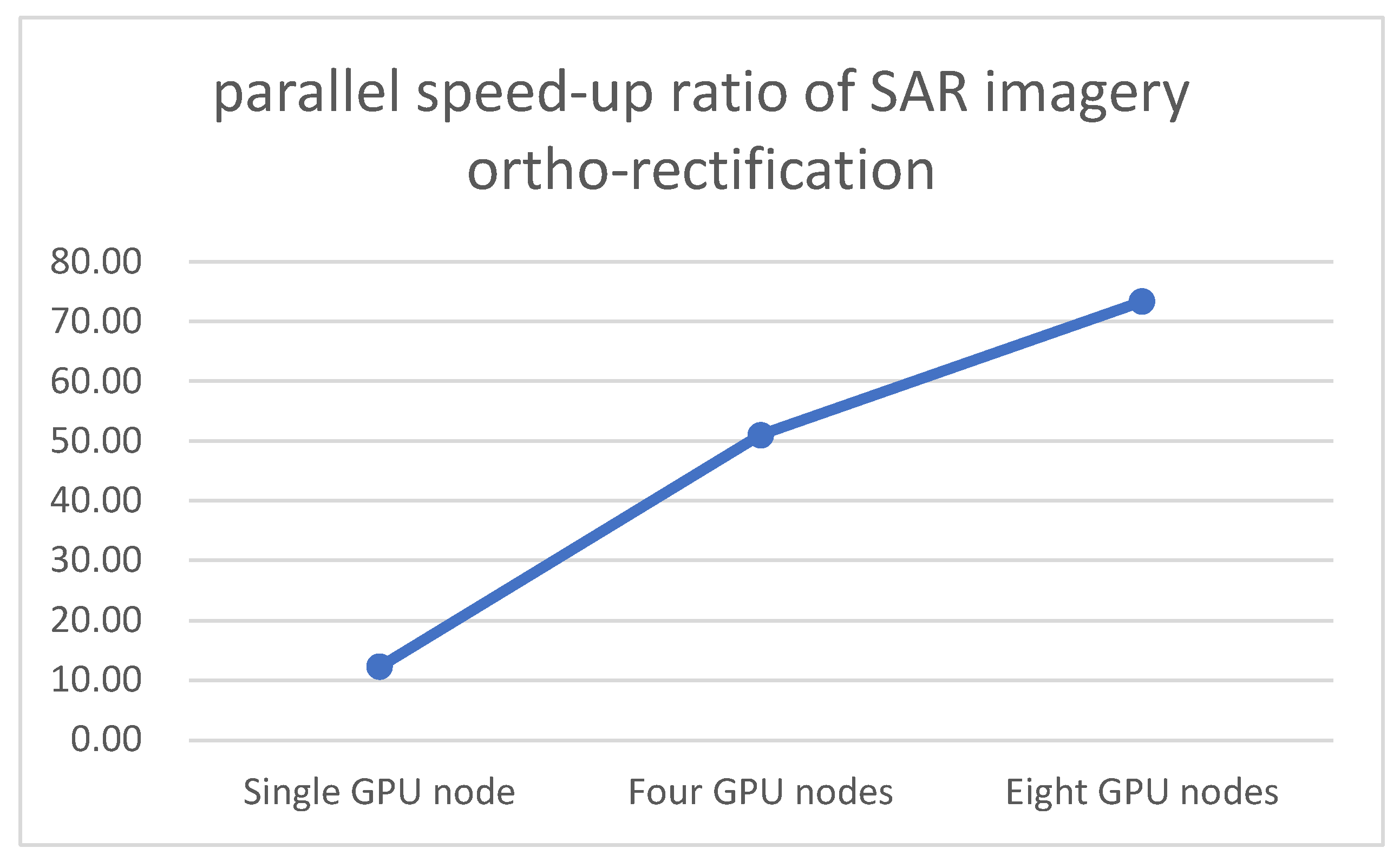
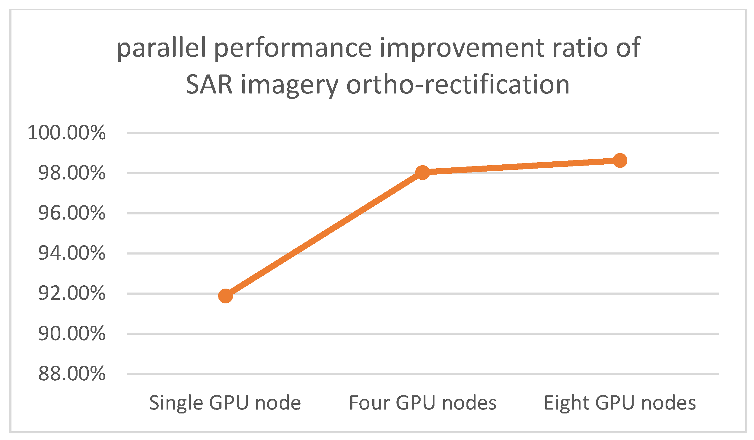
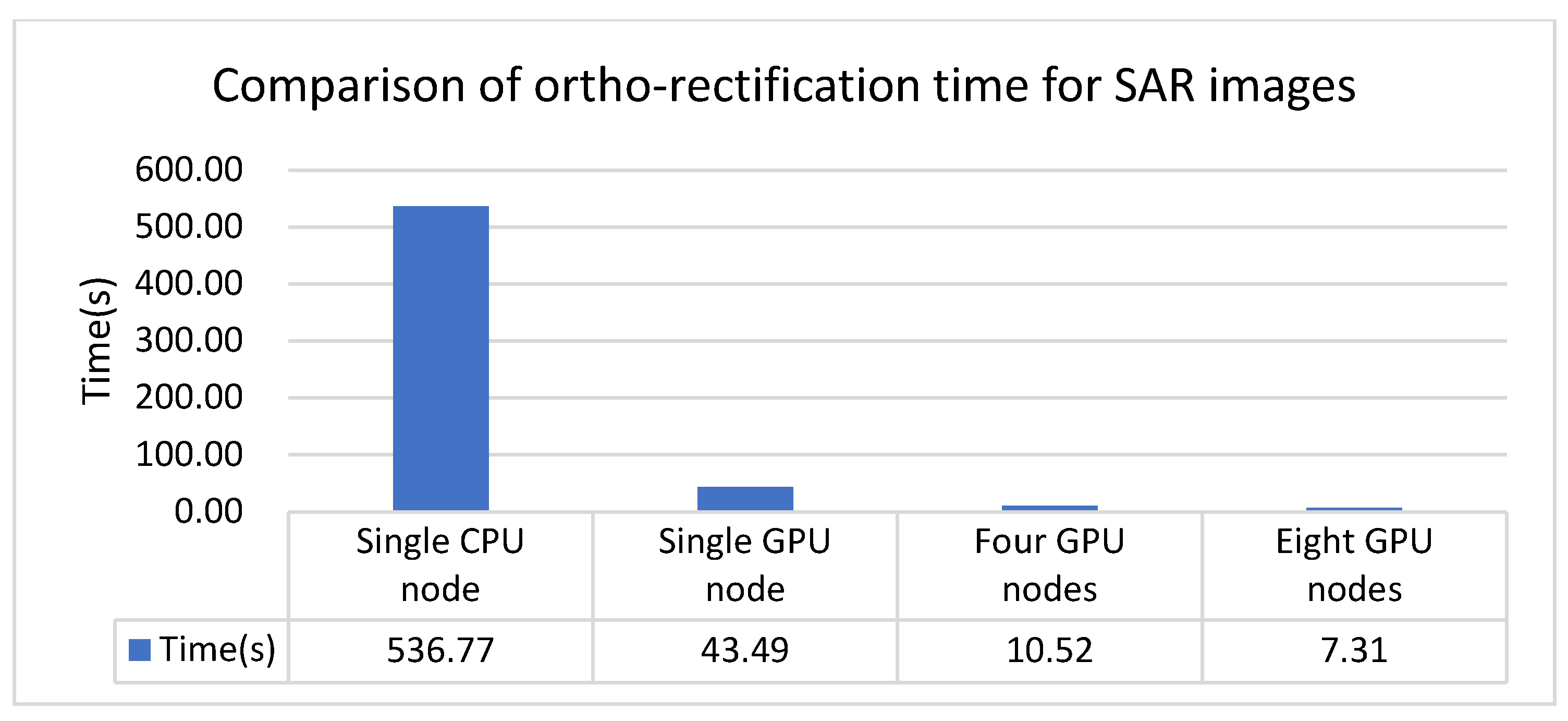
Table 3 shows the time consumption of SAR image ortho-rectification under different strategies, comparing the ortho-rectification time of a single CPU node, a single GPU node, four GPU nodes, and eight GPU nodes. The comprehensive results shown in
Figure 4,
Figure 5 and
Figure 6 indicate the following:
- (1)
When performing ortho-rectification of SAR images on a single node, after GPU processing, the ortho-rectification algorithm achieves a speed-up ratio (ROSU) of 12 and a performance improvement ratio (ROPI) of 91.9% compared with the CPU-based ortho-rectification algorithm, demonstrating the effectiveness of the optimization strategy based on GPU mapping.
- (2)
After processing by multiple nodes, the performance of SAR image ortho-rectification is greatly improved. After parallelization on eight nodes, the GPU-based ortho-rectification algorithm using multiple nodes achieves a speed-up ratio (ROSU) of 73 and a performance improvement ratio (ROPI) of 98.6% compared with the traditional single CPU node, demonstrating the effectiveness of the multi-node GPU parallelization strategy for ortho-rectification.
In conclusion, by optimizing the parallelization strategy of the computational time in the SAR image ortho-rectification process, the resource utilization of the computing nodes can be effectively improved, thereby improving the efficiency of SAR image ortho-rectification.


