Article

Earth Rotation Parameters Derived from BDS-3 New Signals B1C/B2a Dual-Frequency Combination Observations

Institute of Space Sciences, Shandong University, Weihai 264209, China
*
Author to whom correspondence should be addressed.
Remote Sens. 2024, 16(8), 1322; https://doi.org/10.3390/rs16081322
Submission received: 3 March 2024 / Revised: 4 April 2024 / Accepted: 7 April 2024 / Published: 9 April 2024

Abstract

:
The Earth rotation parameters (ERP) play a crucial role in defining the global reference frame and the Global Navigation Satellite System (GNSS) is one of the important tools used to obtain ERP, including polar motion (PM), its rates, and length of day (LOD). The latest IGS Repro3 ERP products, which provided the IGS contribution to the latest ITRF2020, were generated without consideration of the Beidou Navigation Satellite System (BDS) observations. The global BDS, namely the BDS-3 constellation, has been completely constructed from July 2020 and the observing stations are evenly distributed globally now. Two couple dual-frequency combinations, including the B1I/B3I and B1C/B2a combinations, are commonly used for BDS-3 ionosphere-free combination usage. With the goal of identifying the optimal dual-frequency combination for BDS-3 ERP estimates for the future ITRF definition with a consideration of BDS-3, this research evaluated the performance of ERP estimation using B1I/B3I and B1C/B2a combinations. Firstly, we conducted a comparison of the ambiguity resolutions. The mean percentage of successfully resolved ambiguities for the BDS-3 B1C/B2a combination is 86.5%, surpassing that of B1I/B3I. The GNSS satellite orbits and ERP were estimated simultaneously, thus the accuracy of orbits could also reflect the performance of the ERP estimates. Subsequently, we validated the orbits of 22 BDS-3 Medium Earth Orbit (MEO) satellites using Satellite Laser Ranging (SLR), and the root mean square error (RMS) of the SLR residuals for the 3-day arc orbit with B1C/B2a signals was 5.72 cm, indicating superior accuracy compared with the B1I/B3I combination. Finally, we compared the performance of ERP estimation, considering both internal and external accuracy. For the internal accuracy, B1C/B2a-based solutions demonstrated a reduction in mean formal errors of approximately 17% for PM, 22% for LOD, and 21% for PM rates compared with B1I/B3I-based solutions. In terms of external accuracy, we compared BDS-3-derived ERP estimates with the IERS 20C04 products. The B1C/B2a combination exhibited a slightly better standard deviation performance and a significant reduction in mean bias by 56%, 54%, 39%, 64%, and 23% for X, Y polar motion, X, Y polar motion rates, and LOD, respectively, compared with B1I/B3I solutions. In conclusion, the results highlight the excellent signal quality for BDS-3 B1C/B2a and its superiority in ERP estimation when compared with the B1I/B3I combination.

1. Introduction

The Earth Rotation Parameters (ERP), encompassing polar motion (PM) and its rates, along with UT1-UTC and its rate (length of day, LOD), describe the spatiotemporal variations in the Earth’s rotation vector [1]. These parameters play a crucial role in defining a global reference frame and are determined through space geodetic techniques such as Very-Long-Baseline Interferometry (VLBI), Doppler Orbitography and Radiopositioning Integrated by Satellite (DORIS), Satellite Laser Ranging (SLR), and Global Navigation Satellite System (GNSS) [2]. Due to the characteristics of the different techniques, these techniques are sensitive to different aspects of the Earth system [3]. The GNSS technology is predominant in PM estimates because of the dense and uniform global distribution of the observing network, the continuous and high-precision observations, as well as the wide and stable satellite constellation [4,5]. The latest IGS Repro3 ERP products, contributing to the most recent ITRF2020, were generated without incorporating data from the Beidou Navigation Satellite System (BDS). [6,7]. The global BDS, namely BDS-3, has completed its construction which consists of hybrid constellations including Geostationary Earth Orbit (GEO), Inclined Geosynchronous Orbit (IGSO), and Medium Earth Orbit (MEO) satellites [8]. It is worth noting that the BDS-3 MEO satellites were made by two entities including the China Academy of Space Technology (CAST) and the Shanghai Engineering Center for Microsatellites (SECM) [9,10]. The network of ground observing stations for BDS-3 are evenly distributed globally now. The five open service signals of BDS-3 satellites include B1I, B3I, B1C, B2a, and B2b [11]. Notably, B1I and B3I signals are also transmitted by the regional BDS (BDS-2). The B1C, B2a, and B2b signals, unique to BDS-3, are designed to be compatible and interoperable with signals from other GNSSs [12]. For the usage of an ionosphere-free combination, the official interface control document recommends B1C/B2a and B1I/B3I frequency combinations [13,14]. This research aims to assess the ERP derived from observations based on both BDS-3 B1I/B3I and B1C/B2a frequency combinations and seeks to identify the optimal dual-frequency combination for BDS-3 ERP estimates for the future ITRF definition with a consideration of BDS-3.
Many studies related to ERP derived by BDS-3 are based on B1I/B3I dual-frequency combination because most of BDS station receivers only support this frequency couple at the initial stage [9,15,16]. Duan et al. investigated the influence of the solar radiation pressure (SRP) model on BDS orbit, geocenter motion, and ERP estimation as well as estimated the box-wing parameters based on B1I/B3I combination observations, concentrating on BDS satellites with a maximum PRNs of C37 due to receiver limitations from Multi-GNSS Experiment (MGEX) stations at the outset [9]. Afterwards, Peng et al. enhanced ERP estimates from BDS satellites, incorporating box-wing models estimated based on B1I/B3I observations with PRNs extending up to C46 [15]. Fang et al. showcased the advantages of hybrid constellation construction for ERP determination, utilizing IGSO and MEO satellites from BDS with B1I/B3I observations [16]. Jia et al. further investigated the benefits of hybrid BDS constellation construction, considering GEO, IGSO, and MEO satellites, along with a hybrid SRP model [17]. Moreover, He et al. compared the ERP estimated by BDS, GPS, and Galileo and analyzed the features of their systematic bias in ERP [18]. In addition, Wang et al. studied the ERP-obtained discontinuous VLBI observations and BDS-3 based on B1I/B3I measurements [19]. However, these studies for ERP derived from BDS-3 only utilized B1I/B3I observations without a consideration of using BDS-3 B1C/B2a observations.
Recently, many researchers studied the superiority of the BDS-3 B1C/B2a combination on the usage of Precise Point Positioning (PPP), clock offset, and orbit estimation. Yan et al. investigated the superiority of B1C/B2a observation quality for early BDS-3 [20]. Li et al. performed a comparative analysis of BDS-3 orbit determination using B1I/B3I and B1C/B2a observations across nine MGEX stations. Their findings revealed that the accuracy of the BDS-3 orbit generated from B1C/B2a observations was improved by approximately 9% compared with the B1I/B3I-based orbits [21]. Ye et al. evaluated BDS-3 orbits estimated using B1I/B3I and B1C/B2a observations, comparing them with orbits from other MGEX analysis centers. They also validated these orbits using Satellite Laser Ranging (SLR) data, demonstrating that the B1C/B2a-based BDS-3 orbits exhibit superior performance compared with the B1I/B3I-based orbits [22]. He et al. further enhanced BDS-3 MEO orbits with an ambiguity resolution using B1C/B2a observations. Their evaluation results indicated that a higher percentage of ambiguity fixing, lower SLR residuals, and enhanced performance for PPP applications were achieved by using B1C/B2a combination [23]. Geng et al. conducted a comprehensive comparison of data quality, precise orbit determination accuracy, PPP performance, and clock offset product accuracy based on B1C/B2a and B1I/B3I observations. They concluded that B1C/B2a-based results consistently exhibited better performance [24]. However, these studies based on B1C/B2a dual-frequency combination observations did not cover the analyses of the ERP estimates, which need be further investigated. As of November 2021, with over 140 globally distributed MGEX stations supporting B1C/B2a signals [24], there is a significant advantage for ERP estimates based on BDS-3 B1C/B2a observations.
In this research, we present our results as follows. Initially, the observation quality is comprehensively analyzed. Subsequently, the orbit determination results are assessed through orbit overlapping, a comparison with external products, and validation using SLR data. Following this, the ERP derived from BDS-3 B1C/B2a-based observations are thoroughly evaluated. Finally, we provide conclusions based on the analysis results.

2. Methodology

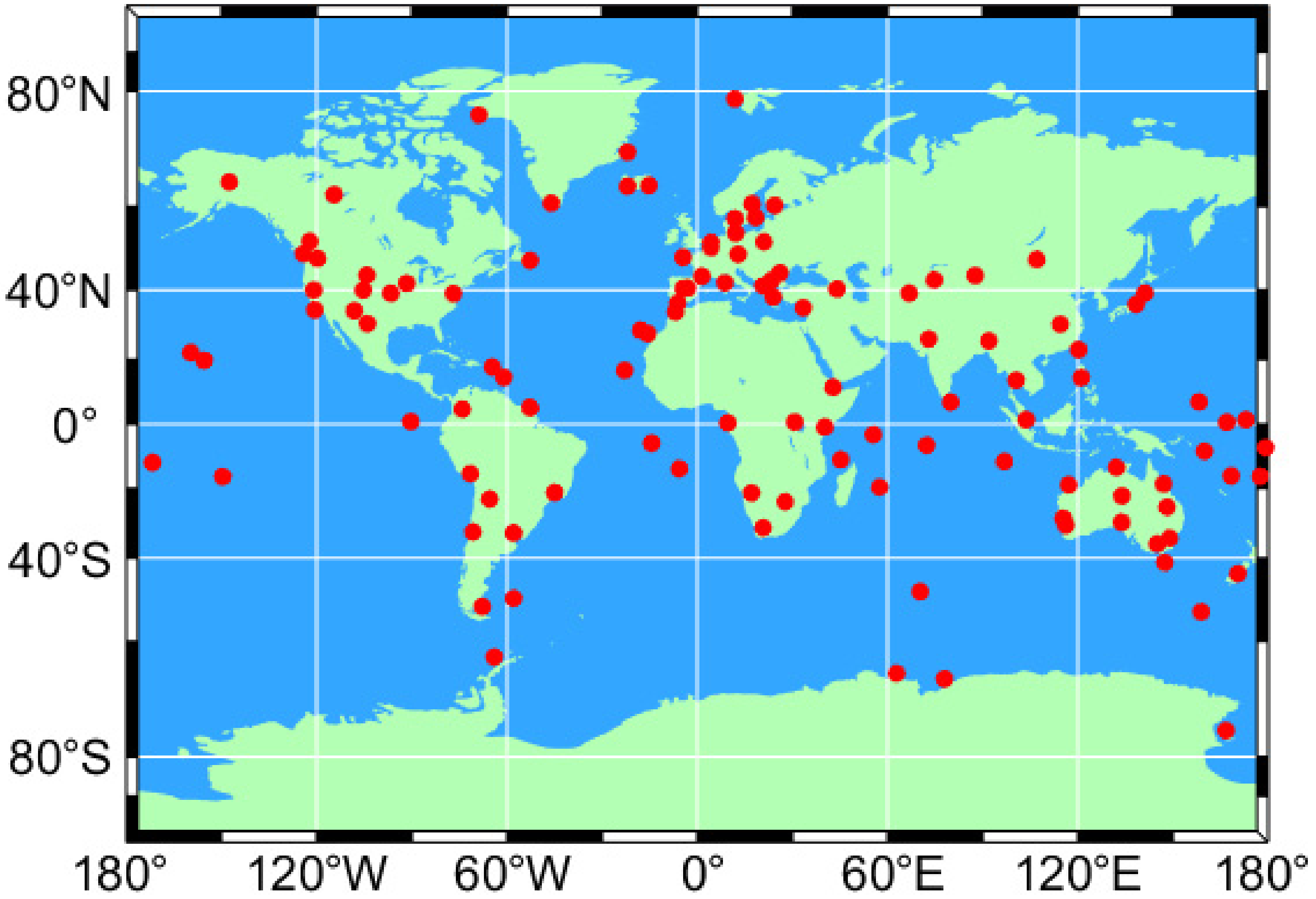
We selected 120 global evenly distributed MGEX stations that support the B1I/B3I and B1C/B2a observations of BDS-3, during the period from 1 October to 31 October 2023. The distribution of the chosen BDS-3 stations is illustrated in Figure 1. Our ERP data processing schemes are outlined in Table 1. Our data processing was performed on BSW54 [25]. The dataset spans one month, covering days of the year (DOY) 274 to 304 in 2023, and we utilized double-difference observations with ionosphere-free (IF) combinations. To achieve high-precision orbit and ERP results, we implemented a two-step process: initially generating 1-day arc solutions, followed by stacking consecutive normal equations of 3 days to obtain the final 3-day arc solutions [26]. ERP estimation was performed with a 24 h resolution, represented by epochs at noon and midnight, utilizing piece-wise linear functions for parameterization. For reference frame selection, we opted for IGS20, which is a realization of ITRF2020 for GNSS [2]. The datum definition was achieved by using IGS20 core stations with minimal constraints including NNR and NNT to align with IGS20. To maintain consistency, we employed antenna models from IGS20.atx for both receivers and satellites, and the phase center variations (PCV) of BDS satellites were not taken into consideration. In this study, the SRP model employed ECOM2 with seven parameters [27]. Sub-daily variations were corrected using the Desai–Sibois model, which is recommended by the 3rd IGS reprocessing campaign [28]. Because of the correlation between orbital elements and UT1-UTC, the GNSS technology could not directly estimate the UT1-UTC parameter [29]. Consequently, we tightly constrained the UT1-UTC of the first epoch to the a priori value from IERS EOP 20C04, which originates from VLBI technology. For the troposphere estimation, we use the Vienna Mapping Function (VMF3) grid product as the a priori model and zenith wet delay was parametrized as piecewise constants with a temporal resolution of 2 h. We use Chen–Herring model as an a priori model and 24 h resolution for troposphere gradients estimates.

3. Observation Quality

In this section, we conducted an analysis of observation quality, focusing on the Signal-to-Noise Ratio (SNR) and multipath errors for four representative stations. The selected example for this analysis is the C46 satellite. Table 2 provides a summary of receiver types for the 120 selected stations. The receivers at these stations can be categorized into eight types, representing four different brands. To illustrate, we selected one representative station for each brand from the most commonly used receiver types.
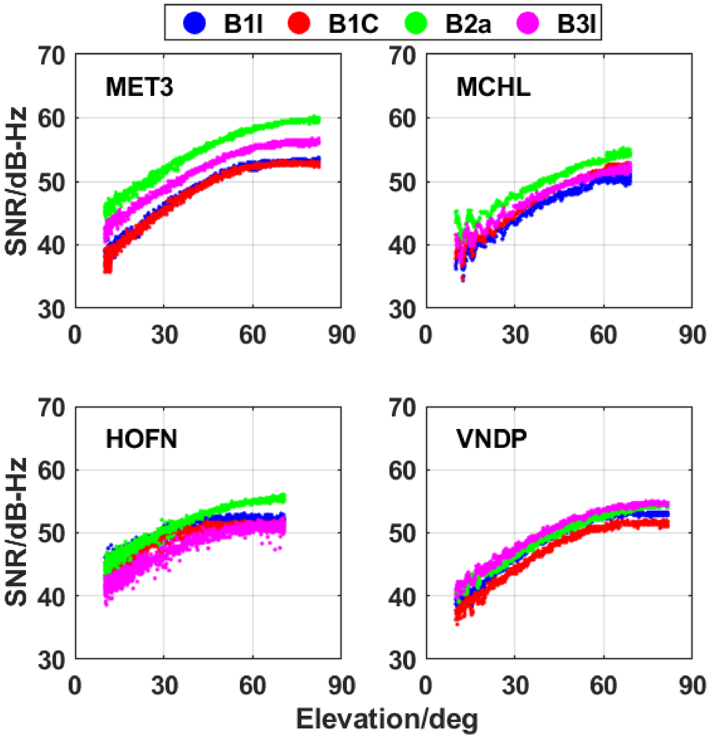
The SNR is a critical indicator for characterizing the signal strength and the receiver’s ability to track signals. We analyzed the SNR for the four frequencies of BDS-3 from four representative stations with an elevation mask angle of 10°. Figure 2 illustrates that SNR increases with the elevation angle, with the MET3 station exhibiting the best signal tracking performance. MET3 particularly excels in B2a, where the SNR can reach up to 60 dB-Hz. Moreover, Table 3 provides the mean SNR for the four BDS-3 frequencies at the selected stations. In Table 3, the mean SNR is approximately 3 dB-Hz stronger for a B2a signal than that for a B3I signal. We can conclude that the B2a signal demonstrates the highest SNR, followed by B3I, while B1C and B1I show comparable SNR values.
The multipath is one of obvious errors in GNSS observations. The multipath can be calculated as follows [40]:
M P i = P i f i 2 + f j 2 f i 2 f j 2 λ i φ i + 2 f j 2 f i 2 f j 2 λ j φ j C i , j
where f i and f j ( i j ) denote the double frequencies. M P i is the multipath of frequency i and P i stands for the pseudorange measurement of frequency i. λ i and λ j represent the wavelengths. φ i and φ j stand for the phase observation of frequency i and j. C i , j denotes the phase ambiguity bias. 
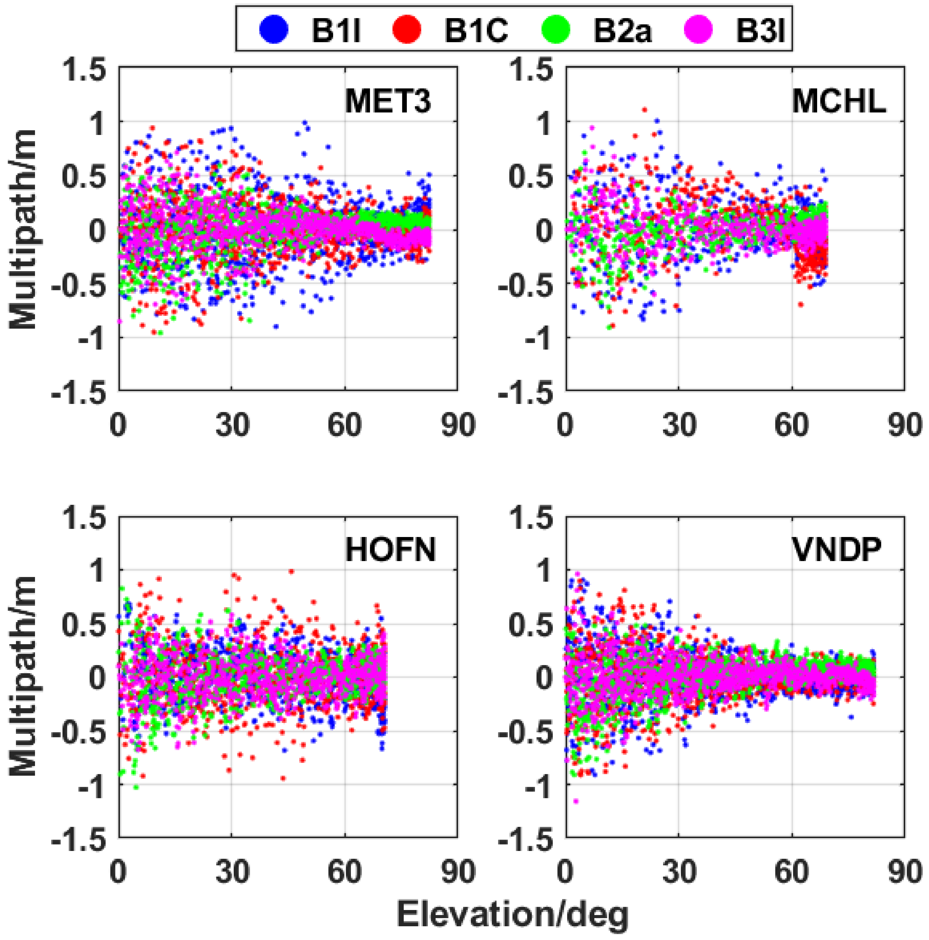
Figure 3 illustrates the multipath analysis of four different BDS-3 frequencies from four stations. The selected stations are from the MGEX network, without obstruction, and are situated far from water areas. The figure depicts that the multipath errors for most epochs are within 0.5 m, and these errors decrease as the elevation angle rises. The mean values and STD of multipath for different BDS-3 frequencies from the four stations are presented in Table 4. The table shows that the mean multipath for each station is close to 0 m. In terms of STD, the B3I signal exhibits the least multipath, approximately 0.17 m, and the value of B2a signal is close to B3I. The B1I signal has the most significant multipath, which is about 0.26 m.

4. Ambiguity Resolution

Ambiguity resolution is a crucial step in achieving GNSS data processing with phase observations. Successfully fixing phase ambiguities to integers in double-difference data processing can be challenging due to observation noise [23]. Double-difference ambiguities are generally categorized into wide-lane (WL) ambiguity and narrow-lane (NL) ambiguity. These two types of ambiguity need to be resolved sequentially. WL ambiguities are typically resolved using the Hatch–Melbourne–Wübbena (HMW) combination, followed by the calculation of NL ambiguities using ionosphere-free and WL ambiguities. The formulas for calculating WL and NL ambiguities are presented below [23,41]:
λ W L N W L = f i f i f j φ i f j f i f j φ j f i f i + f j P i f j f i + f j P j λ N L N N L = N I F λ N L f i / f j 1 N W L
λ W L = λ i λ j λ j λ i λ N L = λ i λ j λ i + λ j
where f i and f j represent the two frequencies we selected for ionosphere-free combination. φ i and φ j are the phase observations while P i and P j are the code observations of the two frequencies. λ W L and λ N L represent the wavelength of WL and NL, which can be calculated by the wavelength λ i and λ j . N W L denote the WL ambiguity and N N L denote the NL ambiguity. N I F is the ionosphere-free combination ambiguity.
When N W L and N N L are fixed to integers, the double-difference ambiguity is resolved successfully. Figure 4 presents the percentage of successfully resolved WL ambiguity and NL ambiguity using BDS-3 B1I/B3I and B1C/B2a combination. The figure indicates that the B1C/B2a achieves a higher percentage of ambiguity fixing compared with the B1I/B3I combination. In detail, the average percentage of fixed WL ambiguities is 89.1% for the B1I/B3I combination and increases to 93.8% for the B1C/B2a solutions. In the case of NL ambiguities, the mean percentage of fixed ambiguities is 68.8% for B1I/B3I and is notably higher at 79.1% for the B1C/B2a combination. Considering all the fixed ambiguities, including both WL and NL, the mean percentage is 78.9% for the B1I/B3I combination, while the B1C/B2a combination demonstrates a 7.6% improvement with a mean percentage of fixed ambiguities.
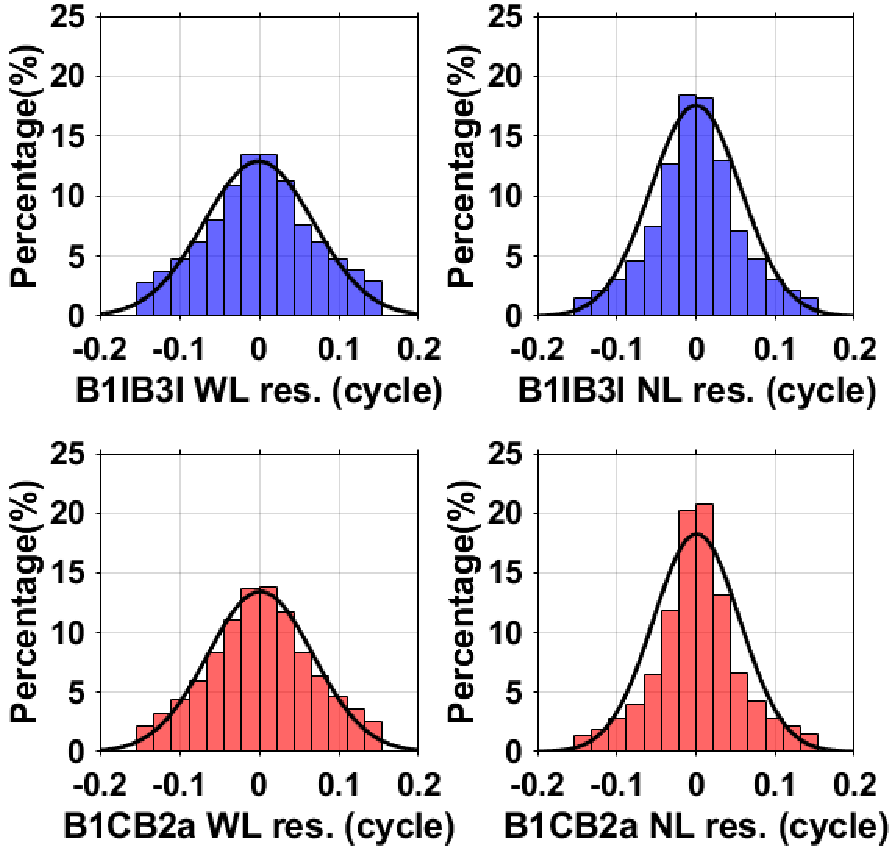
In addition, we conducted a comparison of the residual distributions for WL ambiguity and NL ambiguity between B1I/B3I and B1C/B2a combinations, as illustrated in Figure 5. The black lines in Figure 5 denote the probability density function (PDF) of the residuals, which follows the residual distribution. The plots indicate that the PDFs of WL and NL for both B1I/B3I and B1C/B2a combinations closely adhere to normal distribution. The residual histograms show symmetric distributions centered around zero cycles, particularly for NL ambiguities. The residuals of WL and NL ambiguities represent the disparities between the real values and the fixed values. The mean value, STD, and RMS of the ambiguity residuals are exhibited in Table 5. It presents the average residuals for both WL ambiguity and NL ambiguity, indicating that the mean residuals are near to zero. The RMS values of the residuals for WL ambiguity and NL ambiguity are 0.069 and 0.057 cycles for B1I/B3I, whereas those for B1C/B2a are slightly smaller at 0.066 and 0.055 cycles, respectively. Consequently, the B1C/B2a combination demonstrates superior performance in ambiguity fixing compared with B1I/B3I.

5. Orbit Evaluation

The GNSS satellite orbits and ERP were estimated simultaneously, thus the accuracy of the orbits could also reflect the performance of the ERP estimates. Since the B1C/B2a combination has higher ambiguity fixing percentages and smaller ambiguity fixing residuals, both in the ambiguity resolution of WL and NL, we would like to further investigate the performance of B1C/B2a-based BDS-3 orbit estimation by using orbit overlapping, comparing the orbits with external products and SLR validation. We evaluated the accuracy of the BDS-3 MEO orbits for CAST satellites and SECM satellites, separately because their shapes and the materials of the surfaces used are different, which could present different suitability for the dynamical models for orbit determination [9,10].

5.1. Orbit Overlapping

We conducted a comparison by using the second day from the 3-day arc orbit with the first day from the subsequent 3-day arc orbit as the orbit overlapping. Figure 6 illustrates the RMS of the orbit overlapping for BDS-3 in the radial direction, along direction, cross direction, and 1D directions, employing B1I/B3I combination observations. Figure 7 depicts the RMS of the BDS-3 orbit overlapping using B1C/B2a combination observations. The figure indicates that the mean 1D RMS for B1C/B2a orbit overlapping of the BDS-3 satellites are 1.61 cm and 3.04 cm for MEO and IGSO constellations, respectively. The higher RMS for IGSO satellites can be attributed to the inferior observing geometry compared with MEO. From Figure 6, we can see that the 1D RMS values of the orbit overlapping using the B1I/B3I combination observations are slightly larger than those using B1C/B2a. This discrepancy may be due to the fact that the B1C/B2a solutions achieve a higher rate of ambiguity fixing. In both the B1I/B3I solution and the B1C/B2a solution, the RMS values of orbit overlapping from BDS-3 MEO SECM are within 2 cm, demonstrating smaller RMS compared with BDS-3 MEO CAST. Notably, the most significant orbit overlapping RMS value for BDS-3 IGSO can reach about 4 cm.
Table 6 presents the RMS for B1C/B2a BDS-3 orbit overlapping; the radial component is 1.58 cm, the along component is 2.09 cm, the cross component is 1.86 cm, and the 1D component is 1.86 cm. In detail, the 1D RMS for the BDS-3 orbit overlapping from the B1C/B2a combination is 3.05 cm for IGSO, 1.80 cm for MEO CAST, and 1.30 cm for MEO SECM. Comparatively, the RMS values for the BDS-3 orbit overlapping using B1I/B3I combination observations are slightly larger than those using B1C/B2a combination. This difference may be attributed to the higher percentage of ambiguity fixing to integer achieved by the B1C/B2a solution.

5.2. Comparison with External Products

We conducted a comparative analysis of our BDS-3 3-day arc B1I/B3I orbit results with CODE MGEX (COM) products, as illustrated in Figure 8. Additionally, the results of comparing B1C/B2a orbits are depicted in Figure 9. The RMS values for each BDS-3 satellite orbit compared with CODE MGEX products exhibit a similar level for the B1I/B3I solutions and B1C/B2a solutions. Notably, the RMS values for every MEO SECM satellite orbit are comparable, with most SECM satellites displaying RMS values within 2 cm. The majority of BDS-3 MEO satellite orbits exhibit RMS values lower than 3 cm. However, C45 and C46 satellites stand out with larger RMS values, likely due to fewer tracking stations for these two satellites. The mean 1D RMS of BDS-3 for MEO satellite orbits is 2.07 cm, and for IGSO satellite orbits it is 3.79 cm when using the B1C/B2a combination. These RMS values are slightly larger than the orbits from the B1I/B3I combination, possibly because the CODE MGEX BDS-3 orbits also utilize B1I/B3I combination observations.
The RMS values for the results of the BDS-3 B1I/B3I solution and B1C/B2a solution, encompassing both 1-day and 3-day arc comparisons with CODE MGEX products, are presented in Table 7. Notably, the 3-day arc orbits, both for the BDS-3 B1I/B3I solution and the B1C/B2a solution, exhibit an improvement of approximately 25% compared with the 1-day arc when compared with CODE MGEX orbit products. BDS-3 orbits based on B1I/B3I combinations demonstrate better consistency with the CODE MGEX orbits compared with those using the B1C/B2a combination. This may arise from the fact that CODE MGEX BDS-3 orbits also incorporate B1I/B3I combination observations. The 1D accuracy of BDS-3 orbits, including IGSO satellites and MEO satellites, is 2.35 cm when using the B1C/B2a combination in comparison with the CODE MGEX orbits. In detail, the 1D accuracy of the IGSO satellite orbit is 3.73 cm. The 1D orbit accuracy for the MEO CAST satellite is 2.27 cm and that for the MEO SECM satellite is 1.78 cm.

5.3. SLR

SLR as a pivotal space technology enables the independent orbit accuracy validation of GNSS satellites. To facilitate SLR tracking, every BDS-3 MEO satellite is equipped with laser retroreflector arrays (LRA). Thus, we can carry out SLR validation for these BDS-3 MEO satellites. Since February 2023, ILRS SLR tracking mission has added all BDS-3 MEO satellites into its observation list [42]. In this study, SLR was employed to validate the orbits for BDS-3, excluding satellite C27 and satellite C28 as their SLR observations were not available. For reference, SLR validation was also applied to BDS-3 orbit products from CODE. Figure 10 exhibits the SLR validation results for 3-day arc orbits of BDS-3 MEO. The mean RMS of the BDS-3 satellite orbits from the B1C/B2a observations is 5.72 cm, slightly outperforming the B1I/B3I combination and CODE MGEX products. Most BDS-3 satellite orbits using SLR validation exhibit RMS values smaller than 6 cm. Only three satellites’ orbit RMS values exceeded 8 cm, with satellite C44 having the largest RMS, reaching about 18 cm. The significant SLR residuals of C43 and C44 may be caused by the errors in the published metadata associated with the LRA [43]. The mean RMS of SLR validation for BDS-3 satellites’ 3-day arc orbits, excluding C22, C43, and C44, is 4.47 cm for the B1I/B3I solution, 4.40 cm for the B1C/B2a solution, and 4.51 cm for the CODE solution, respectively. Among these three solutions, the B1C/B2a solution consistently demonstrates the best performance.
The RMS values of SLR residuals for BDS-3 MEO orbits, obtained from B1I/B3I and B1C/B2a combination observations, including 1-day and 3-day arcs, along with CODE MGEX products, are exhibited in Table 8. Notably, the RMS values are slightly smaller for the 3-day arc orbits than those for the 1-day arc. For all BDS-3 orbits, the RMS value of the SLR residuals is 6.41 cm for the B1I/B3I solution, 6.39 cm for the B1C/B2a solution, and 6.38 cm for CODE MGEX products. It is essential to emphasize that the RMS values for BDS-3 MEO SECM SLR residuals are over 8 cm, which is more obvious than those of CAST satellites because of the larger residuals of SLR for satellites C43 and C44. Table 9 summarizes the RMS values of the SLR residuals for MEO satellite 3-day arc solutions, excluding satellites C22, C43, and C44, which have SLR residuals exceeding 8 cm. According to the statistics, the RMS values are 4.75 cm for the B1I/B3I solution, 4.69 cm for the B1C/B2a solution, and 4.70 cm for the CODE MGEX products. These results further emphasize that the B1C/B2a solution exhibits the best performance for the determination of the BDS-3 orbit.

6. Earth Rotation Parameters Evaluation

Detailed investigation into the ERP, as a fundamental aspect of the reference frame definition, is essential. We evaluated ERP from BDS-3 with B1C/B2a combination observations by using the formal error index and comparing with the external IERS 20C04 products. For purpose of comparison, we also calculated and evaluated the ERP generated by the B1I/B3I combination observations of BDS-3 satellites and by GPS satellites.

6.1. Formal Error

The formal errors are usually used as indicators of precision and observability for the estimated parameter [3]. The formula for calculating formal errors is presented as follows:
Q x x = σ 0 2 N 1
where σ 0 2 is the a posteriori variance factor of unit weight and N is the normal equation matrix. We use the formal error as an indication of internal accuracy.
Figure 11 displays the time series of formal errors in ERP estimation from the 3-day arc BDS-3 B1I/B3I solutions, B1C/B2a solutions, and GPS solutions. The figure illustrates that GPS solutions exhibit the minimal formal errors for PM, its rates, and LOD. The formal errors of the B1C/B2a-based solutions closely align with those of the GPS solutions and are smaller than the B1I/B3I-based solutions. Table 10 summarized the mean formal errors in ERP estimation using BDS-3 satellites from the B1I/B3I solutions and B1C/B2a solutions. The table reveals that the mean formal errors from the 3-day arc solutions are approximately 2.2 times smaller for PM, 4 times smaller for PM rates, and 2.5 times smaller for LOD than the 1-day arc solutions. In particular, the mean formal errors in ERP estimation from the 3-day arc B1C/B2a solutions are approximately 10 μas for PM, 12 μas/d for PM rates, and 0.7 μs/d for LOD. The B1C/B2a-based solutions contribute to a reduction in the mean formal errors by about 17% for PM, 22% for LOD, and 21% for PM rates when compared with B1I/B3I-based solutions.

6.2. Comparison with IERS 20C04 Products

In the external accuracy evaluation, we compared the estimated ERP results with reference to the IERS 20C04 products. Figure 12 exhibits the time series of PM differences with reference to IERS 20C04 products for 3-day arc BDS-3 B1I/B3I solutions, B1C/B2a solutions, and GPS solutions. From Figure 12, it is evident that the RMS of the B1C/B2a solution is 80 μas for X PM and 51 μas for Y PM. These values are 37% and 20% smaller than the B1I/B3I-based solutions for X and Y PM. In comparison, the RMS values of PM for GPS-based solutions are approximately 30 μas. Figure 13 illustrates the time series for LOD differences with reference to IERS 20C04 products from 3-day arc BDS-3 B1I/B3I solutions, B1C/B2a solutions, and GPS solutions. The results demonstrate that the RMS of the LOD series for the B1C/B2a solution is 22.3 μs/d, which is 1% smaller than the B1I/B3I solution. In Figure 14, the time series of the PM rate differences with reference to IERS 20C04 products for the 3-day arc BDS-3 B1I/B3I solutions, B1C/B2a solutions, and GPS solutions are presented. The RMS from the BDS-3 B1C/B2a solution is 124 μas/d for the X PM rate and 101 μas/d for the Y PM rate. These values are smaller by 7% for the X PM rate and 4% for the Y PM rate compared with the PM rates from the B1I/B3I solutions.
Table 11 presents the mean bias and STD of ERP differences when compared with IERS 20C04 products for the B1I/B3I solutions and B1C/B2a solutions, with GPS solutions included as a reference. The improvements in STD for the 3-day arc results are approximately 35% for pole coordinates, 30% for LOD, 65% for X pole coordinates, and 80% for Y pole coordinates, compared with the 1-day arc ERP from BDS-3. The mean values of the 3-day arc ERP from the BDS-3 B1C/B2a combination, with reference to IERS 20C04, are 48 μas and 19 μas for X and Y PM, 17 μas/d, and 5 μas/d for the X PM rate and the Y PM rate, and 4 μs/d for LOD. The mean values of the residuals for the 3-day arc BDS-3 B1C/B2a solutions show improvements of 56%, 54%, 20%, 39%, and 64% for the X, Y PM, LOD, X, and Y PM rates, respectively, compared with BDS-3 B1I/B3I solutions. The superior mean bias of the B1C/B2a-based ERP can be attributed to the advantage of the B1C/B2a combination in ambiguity fixing. In the aspect of STD, the results of the 3-day arc ERP from the BDS-3 B1C/B2a combination are 63 μas, 47 μas, 123 μas/d, 101 μas/d, and 22.0 μs/d for the X, Y PM, X, and Y PM rates, and LOD, respectively. The B1C/B2a solutions result in standard deviations of the residuals that are about 3%, 2%, 1%, 6%, and 3% better than the B1I/B3I solutions for the X, Y PM, X, and Y PM rates, and LOD, respectively. While the GPS solutions generally exhibit better mean and STD than BDS-3 ERP, it is worth noting that the mean bias of the LOD in the GPS solutions is larger, approximately 1.5 times higher than the BDS-3 result. This discrepancy arises because the orbital period of GPS exhibits a stronger resonance with the Earth’s rotation, which is 2:1. While the corresponding resonance for BDS-3 is weaker, approximately at a 17:9 ratio [5,15,16].

7. Conclusions

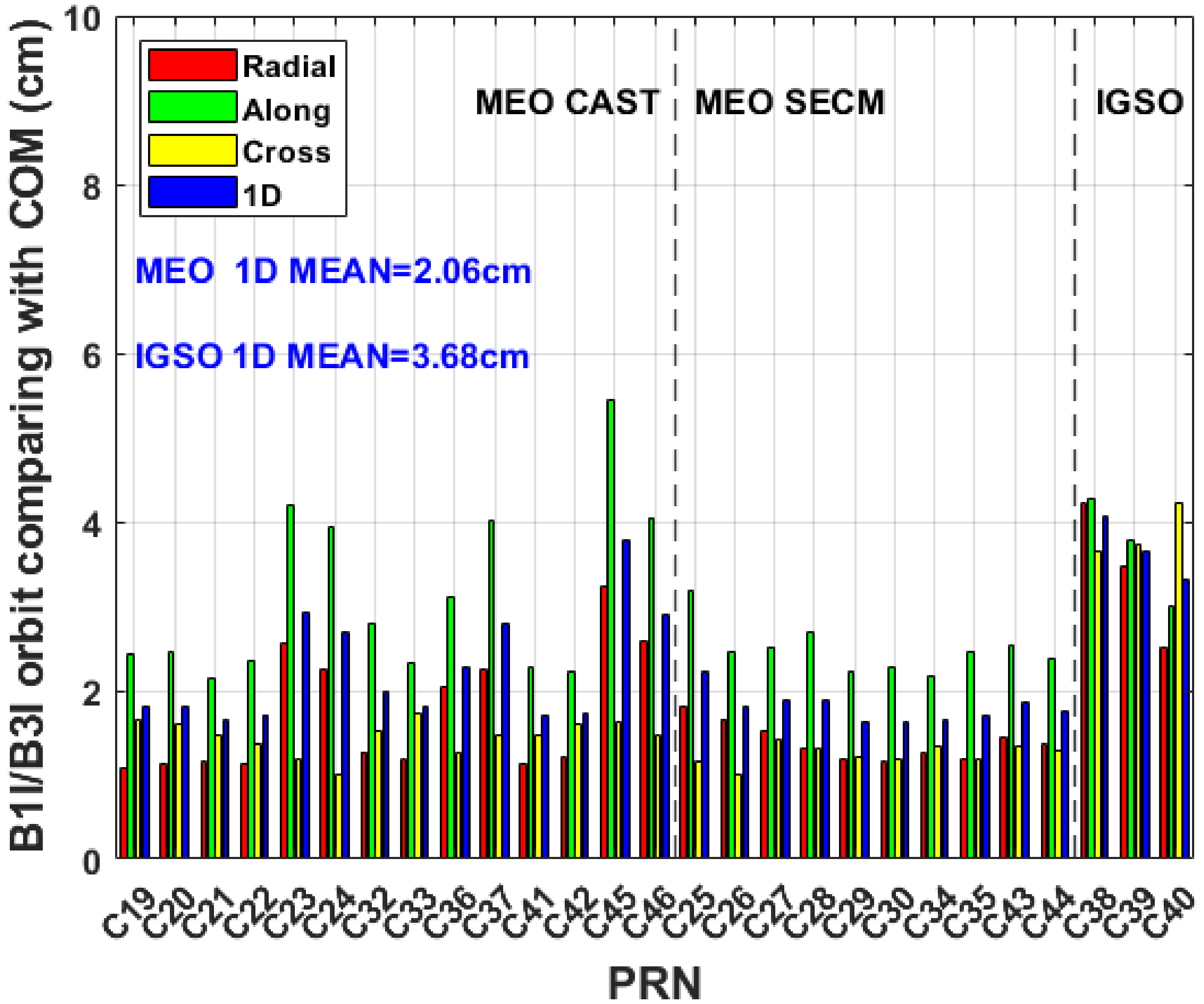
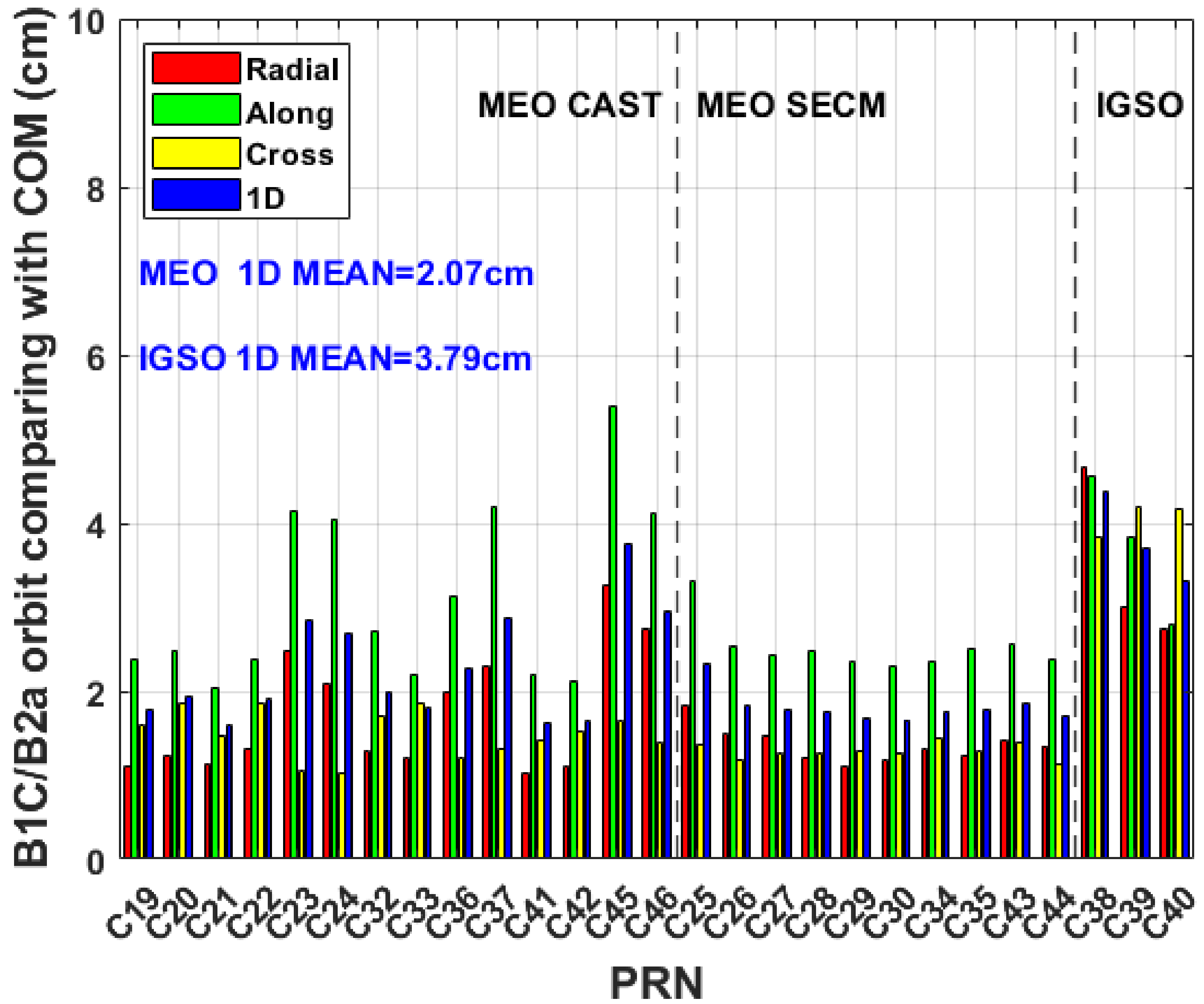
The ERP constitute a crucial component in defining the global reference frame, and GNSS serves as a vital technology for obtaining ERP, including PM, its rates, and LOD. The latest IGS Repro3 ERP products provided the IGS contribution to the latest ITRF2020, but without consideration of the BDS observations. In this study, the ERP and the orbits generated from the BDS-3 B1I/B3I observations and B1C/B2a observations were calculated in the ITRF2020. The evaluation of these parameters was conducted, and the validation of 22 BDS-3 MEO orbits using SLR was also performed.
Firstly, we evaluated the signal quality from several indicators. SNR is an important index of characterizing the signal strength. The B2a signal has the largest SNR, then the second one is B3I and the SNR of B1C is comparable with B1I. The other indicator of observation quality is multipath. The ranking of multipath errors is B3I < B2a < B1C < B1I. Ambiguity resolution is one of crucial steps in GNSS data processing with phase observations, and the B1C/B2a combination has a higher percentage of ambiguity fixing than the B1I/B3I combination. The mean percentage of all fixed ambiguities including WL and NL is 78.9% for the B1I/B3I combination and the mean percentage for the B1C/B2a combination is higher, which is 86.5%.
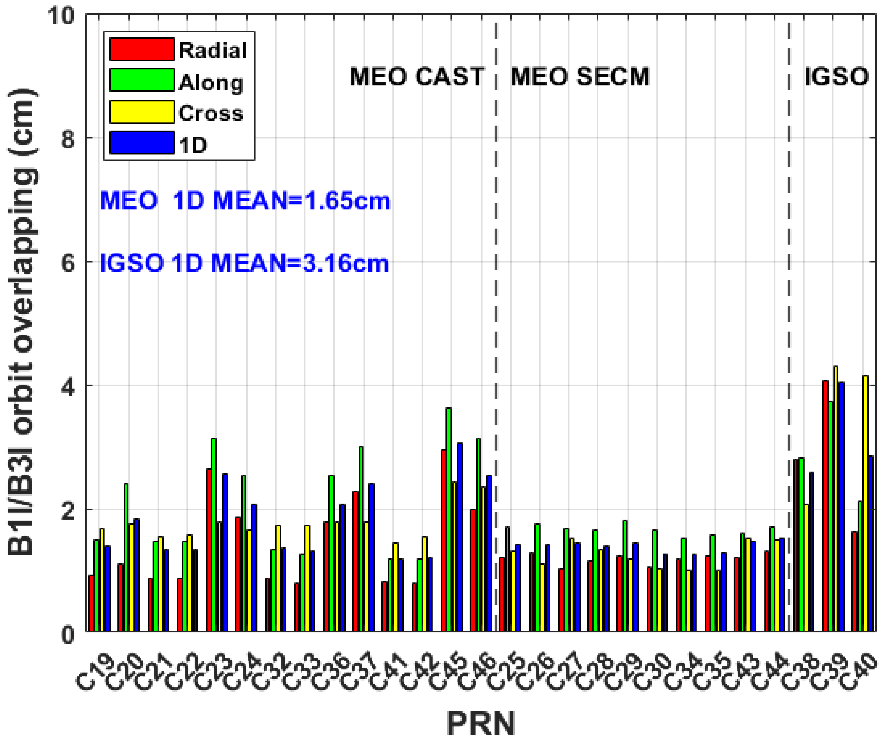
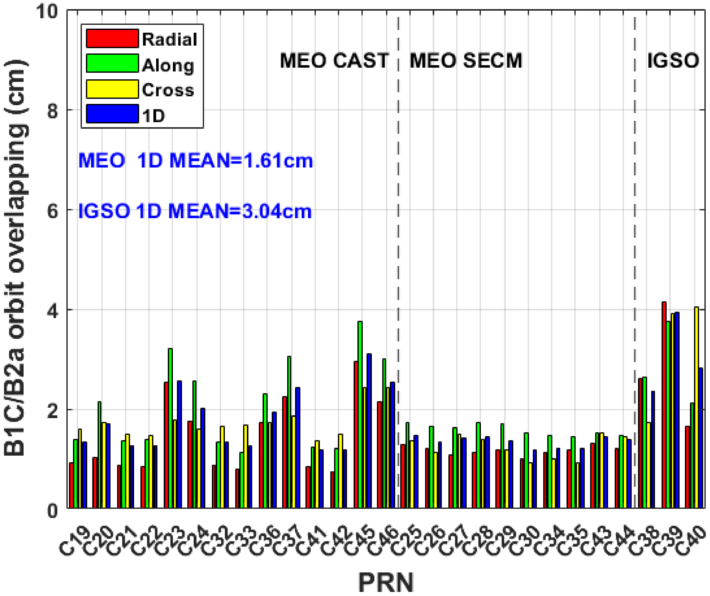
Subsequently, the precision of the satellite orbits was compared by using orbit overlapping. The RMS for the B1C/B2a-based BDS-3 orbit overlapping was calculated for radial component, along component, cross component, and 1D component, yielding values of 1.58 cm, 2.09 cm, 1.86 cm, and 1.86 cm, respectively. It is noteworthy that the RMS values for the BDS-3 orbit overlapping, employing the B1I/B3I combination, are slightly higher compared with the B1C/B2a solution. This discrepancy may be thanks to the higher percentage of ambiguity fixing to integers in the B1C/B2a combination.
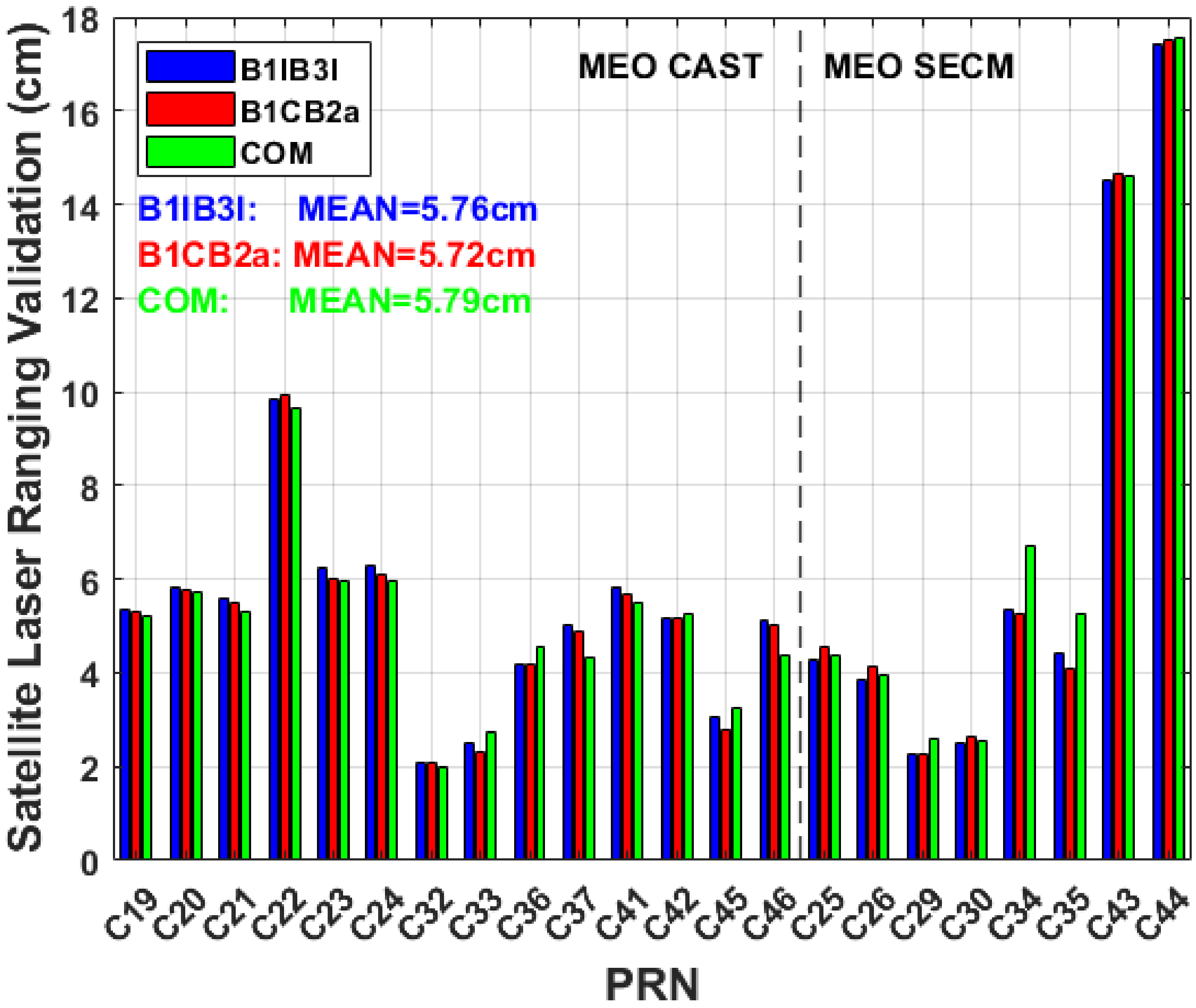
Satellite Laser Ranging, as one of key space technologies, can realize the orbit accuracy validation of GNSS satellites independently. The mean RMS of SLR residuals is 5.72 cm for 3-day arc orbits of 22 BDS-3 satellites from the B1C/B2a solution and 4.40 cm for BDS-3 satellite orbits without consideration of satellites C22, C43, and C44, which are both slightly better than the B1I/B3I combination and CODE MGEX products.
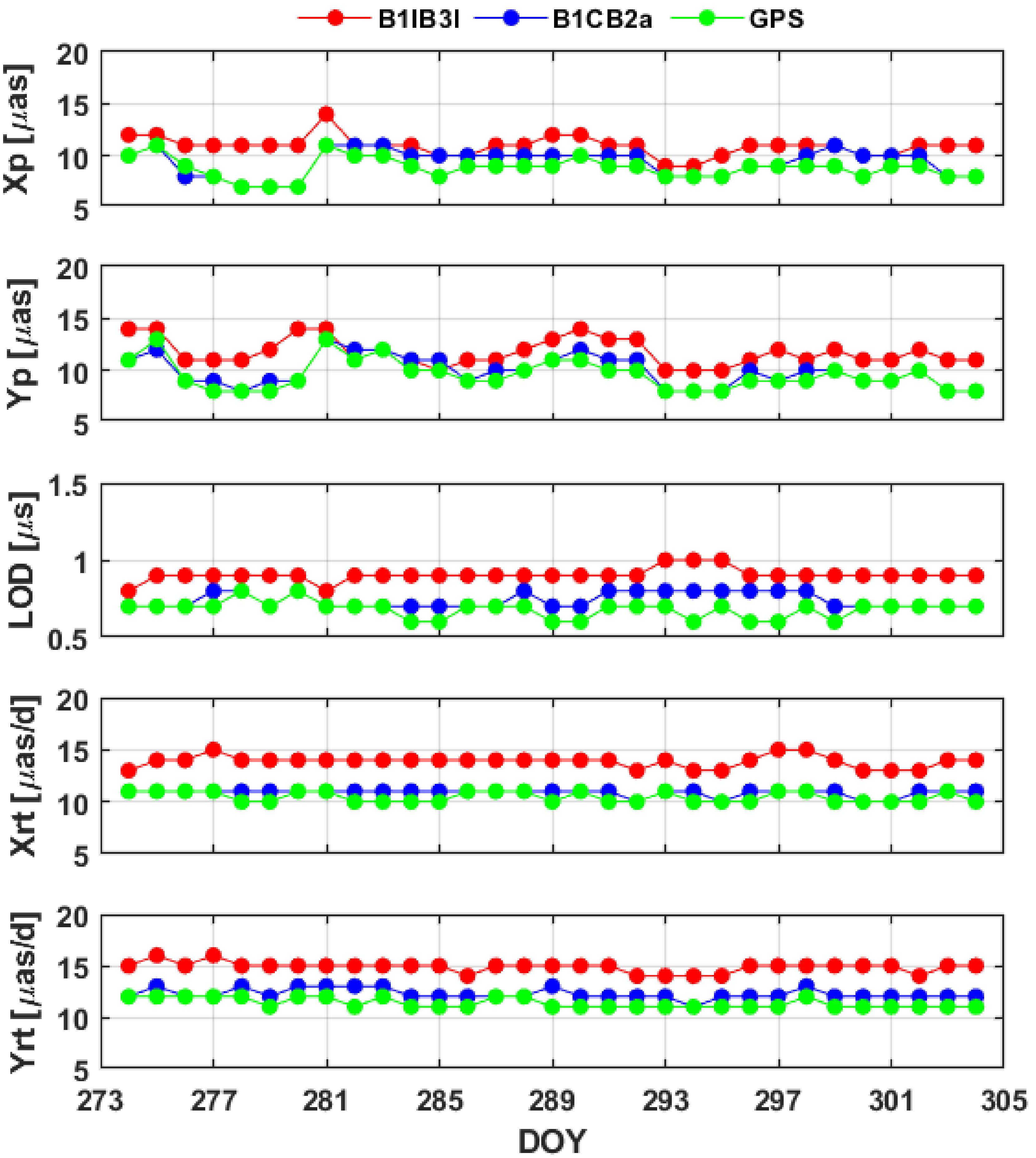
Finally, we assessed the accuracy of ERP estimates from the aspect of internal and external accuracy, particularly focusing on the formal errors in ERP estimation and the disparities between the estimated ERP values and the 20C04 products. The mean formal errors of the 3-day arc ERP estimates derived from B1C/B2a combination observations are approximately 10 μas for PM, 12 μas/d for PM rates, and 0.7 μs/d for LOD. Comparatively, the utilization of B1C/B2a-based solutions results in a reduction of mean formal errors by about 17% for pole coordinates, 22% for LOD, and 21% for pole coordinate rates when compared with B1I/B3I-based solutions.
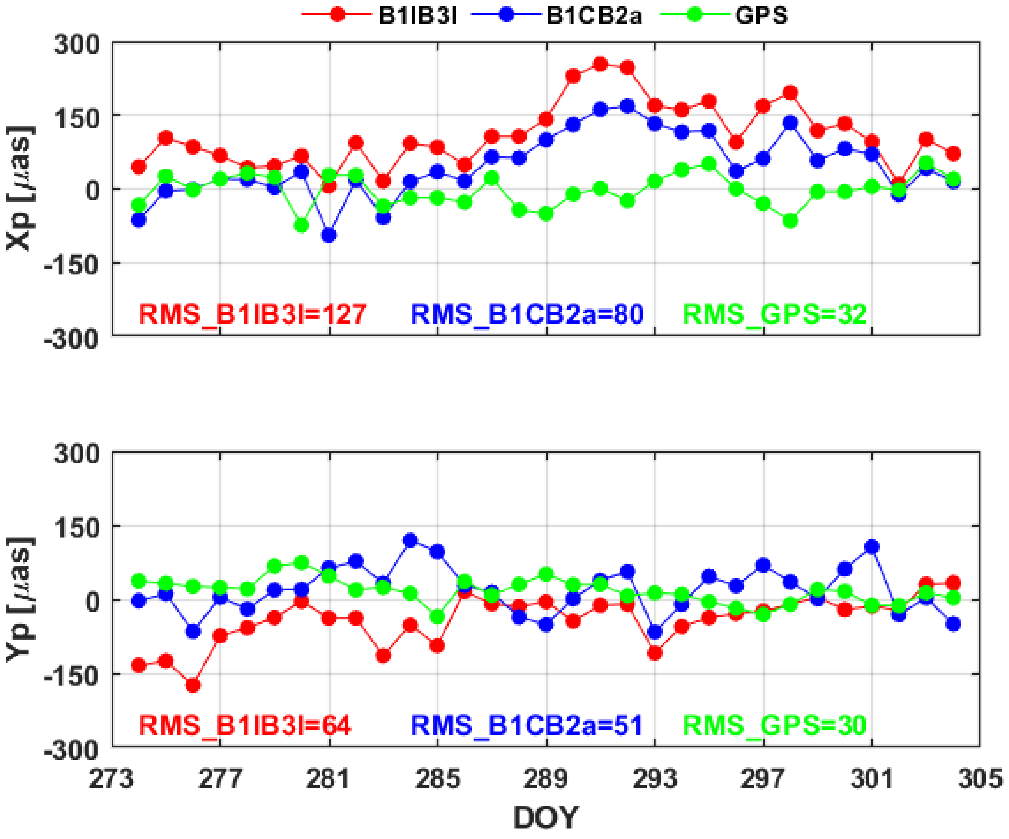
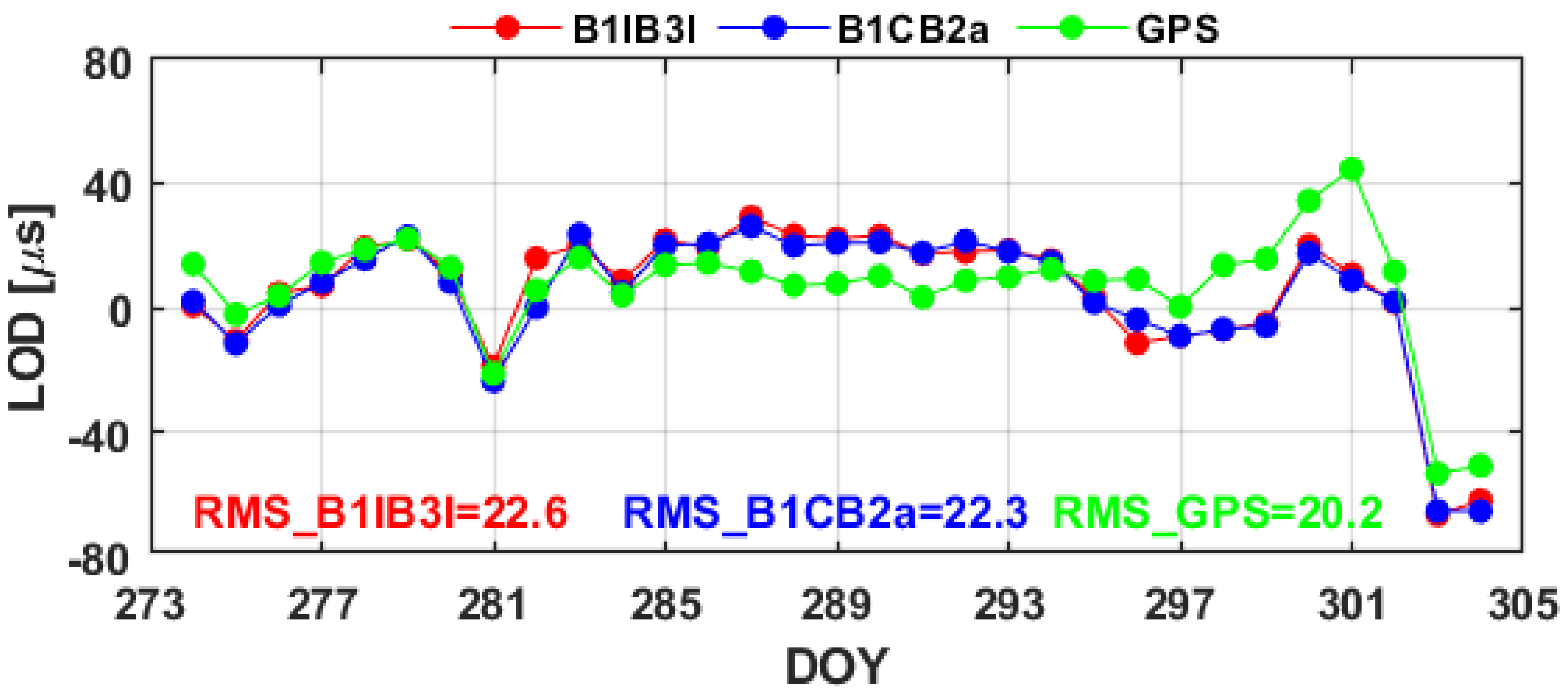
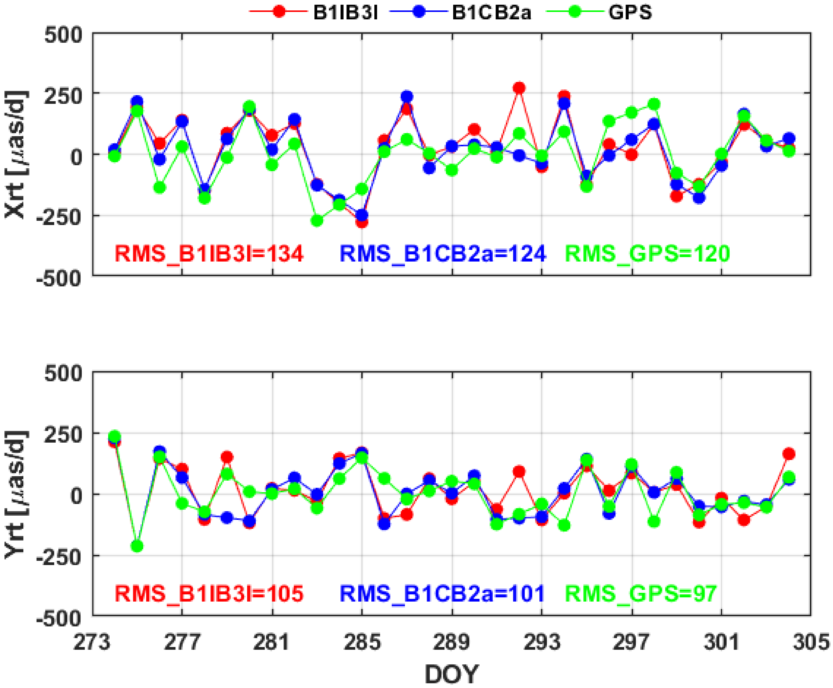
Regarding the external accuracy, the mean differences of the 3-day arc ERP estimates from the BDS-3 B1C/B2a combination, with reference to IERS 20C04, are 48 μas for X PM, 19 μas for Y PM, 17 μas/d for X PM rate, 5 μas/d for Y PM rate, and 4.0 μs/d for LOD. The utilization of the BDS-3 B1C/B2a combination leads to a noteworthy improvement, with mean differences reduced by 56% for X PM, 54% for Y PM, 39% for the X PM rate, 64% for the Y PM rate, and 23% for LOD, in comparison with B1I/B3I. In the aspect of STD, the outcomes for the 3-day arc ERP estimates from the BDS-3 B1C/B2a combination are as follows: 63 μas for X PM and 47 μas for Y PM, 123 μas/d for the X PM rate, 101 μas/d for the Y PM rate, and 22.0 μs/d for LOD. The B1C/B2a solutions result in STDs of residuals that are approximately 3% for X PM, 2% for Y PM, 1% for X PM rate, 6% for Y PM rate, and 3% for LOD, better than the B1I/B3I solutions.
Therefore, the results demonstrate the excellent signal quality for the BDS-3 B1C/B2a and its superiority in the ERP estimation when comparing with the B1IB3I combination. Since the number and distribution of MGEX stations supporting B1C/B2a signals tracking are inferior to the B1I/B3I tracking stations, the performance of ERP derived from BDS-3 B1C/B2a signals maybe better with more global MGEX stations supporting BDS-3 B1C/B2a signals tracking in the future or adding Low Earth Orbit satellite observations.

Author Contributions

T.X. and Z.F. proposed the idea of this study. Z.F. performed the experiments and analyzed the data. T.X., Z.F. and W.N. discussed the results. Z.F. and W.N. prepared the original manuscript. Z.F., Y.Y. and M.L. developed and modified the software. All authors have read and agreed to the published version of the manuscript.

Funding

This research was supported by the National Natural Science Foundation of China (Grant No. 42388102 and No. 42204015), the China Post-doctoral Science Foundation (2023M732041), Youth Innovation Team Development Project of Higher School in Shandong Province (2023KJ143), and the Young Scholars Program of Shandong University, Weihai.

Data Availability Statement

In this study, the GNSS observation data can be downloaded from https://cddis.nasa.gov/archive/gps/data/daily/ (accessed on 25 February 2024), the CODE MGEX products are available at http://ftp.aiub.unibe.ch/CODE_MGEX/CODE/ (accessed on 25 February 2024), the SLR observation data can be found at https://cddis.nasa.gov/archive/slr/data/ (accessed on 25 February 2024), and the IERS 20C04 products are available at https://hpiers.obspm.fr/iers/eop/eopc04/ (accessed on 25 February 2024).

Acknowledgments

The authors would like to thank IGS for providing MGEX GNSS data and the CODE analysis center for providing MGEX products. The ILRS and EDC are acknowledged for providing SLR data and the IERS is acknowledged for providing IERS 20C04 products. The numerical calculations in this paper have been performed on the supercomputing system in the Supercomputing Center, Shandong University, Weihai.

Conflicts of Interest

The authors declare no conflicts of interest.

References

  1. Schuh, H.; Böhm, S. Earth rotation. In Encyclopedia of Solid Earth Geophysics; Springer: Berlin/Heidelberg, Germany, 2021; pp. 149–155. [Google Scholar]
  2. ITRF. ITRF Solutions. Available online: https://itrf.ign.fr/en/solutions (accessed on 25 February 2024).
  3. Zajdel, R. Determination of Global Geodetic Parameters Using the Gps, Glonass, and Galileo Satellite Systems. Ph.D. Thesis, Wrocław University of Environmental and Life Sciences, Wrocław, Poland, 2021. [Google Scholar]
  4. Ray, J.; Rebischung, P.; Griffiths, J. IGS polar motion measurement accuracy. Geod. Geodyn. 2017, 8, 413–420. [Google Scholar] [CrossRef]
  5. Zajdel, R.; Sośnica, K.; Bury, G.; Dach, R.; Prange, L. System-specific systematic errors in earth rotation parameters derived from GPS, GLONASS, and Galileo. GPS Solut. 2020, 24, 74. [Google Scholar] [CrossRef]
  6. Altamimi, Z.; Rebischung, P.; Collilieux, X.; Métivier, L.; Chanard, K. ITRF2020: An augmented reference frame refining the modeling of nonlinear station motions. J. Geod. 2023, 97, 47. [Google Scholar] [CrossRef]
  7. Zajdel, R.; Masoumi, S.; Sośnica, K.; Gałdyn, F.; Strugarek, D.; Bury, G. Combination and SLR validation of IGS Repro3 orbits for ITRF2020. J. Geod. 2023, 97, 87. [Google Scholar] [CrossRef]
  8. CSNO. BeiDou Navigation Satellite System. Available online: http://en.beidou.gov.cn/ (accessed on 25 February 2024).
  9. Duan, B.; Hugentobler, U.; Selmke, I.; Marz, S.; Killian, M.; Rott, M. BeiDou satellite radiation force models for precise orbit determination and geodetic applications. IEEE Trans. Aerosp. Electron. Syst. 2022, 58, 2823–2836. [Google Scholar] [CrossRef]
  10. Zhao, Q.; Guo, J.; Wang, C.; Lyu, Y.; Xu, X.; Yang, C.; Li, J. Precise orbit determination for BDS satellites. Satell. Navig. 2022, 3, 2. [Google Scholar] [CrossRef]
  11. CSNO. BeiDou Navigation Satellite System Open Service Performance Standard; Version 3.0; CSNO: Sacramento, CA, USA, 2021. [Google Scholar]
  12. Yang, Y.; Xu, Y.; Li, J.; Yang, C. Progress and performance evaluation of BeiDou global navigation satellite system: Data analysis based on BDS-3 demonstration system. Sci. China Earth Sci. 2018, 61, 614–624. [Google Scholar] [CrossRef]
  13. CSNO. BeiDou Navigation Satellite System Signal in Space Interface Control Document Open Service Signal B1I; Version 3.0; CSNO: Sacramento, CA, USA, 2019. [Google Scholar]
  14. CSNO. BeiDou Navigation Satellite System Signal in Space Interface Control Document Open Service Signal B1C; Version 1.0; CSNO: Sacramento, CA, USA, 2017. [Google Scholar]
  15. Peng, Y.; Lou, Y.; Dai, X.; Guo, J.; Shi, C. Impact of solar radiation pressure models on earth rotation parameters derived from BDS. GPS Solut. 2022, 26, 126. [Google Scholar] [CrossRef]
  16. Fang, Z.; Xu, T.; Nie, W.; Yang, Y.; Li, M. Earth rotation parameters from GPS and BDS: Contributions from MEO and IGSO satellites. Adv. Space Res. 2023, 71, 3091–3108. [Google Scholar] [CrossRef]
  17. Jia, S.; Li, B.; Ge, H.; Qiao, J. Determination of Earth rotation parameters by Beidou navigation satellite system. Adv. Space Res. 2023, 72, 1764–1779. [Google Scholar] [CrossRef]
  18. He, Z.; Wei, E.; Zhang, Q.; Wang, L.; Li, Y.; Liu, J. Earth rotation parameters from BDS, GPS, and Galileo data: An accuracy analysis. Adv. Space Res. 2023, 71, 3968–3980. [Google Scholar] [CrossRef]
  19. Wang, C.; Sang, J.; Li, X.; Zhang, P. Estimation of Earth Rotation Parameters based on the BDS3 and discontinuous VLBI observation. Remote Sens. 2023, 16, 333. [Google Scholar] [CrossRef]
  20. Yan, X.; Huang, G.; Zhang, Q.; Liu, C.; Wang, L.; Qin, Z. Early analysis of precise orbit and clock offset determination for the satellites of the global BeiDou-3 system. Adv. Space Res. 2019, 63, 1270–1279. [Google Scholar] [CrossRef]
  21. Li, R.; Wang, N.; Li, Z.; Zhang, Y.; Wang, Z.; Ma, H. Precise orbit determination of BDS-3 satellites using B1C and B2a dual-frequency measurements. GPS Solut. 2021, 25, 95. [Google Scholar] [CrossRef]
  22. Ye, F.; Yuan, Y.; Yang, Z. Validation and evaluation on B1IB3I-based and B1CB2a-based BDS-3 precise orbits from iGMAS. Adv. Space Res. 2022, 70, 2167–2177. [Google Scholar] [CrossRef]
  23. He, L.; He, X.; Huang, Y. Enhanced precise orbit determination of BDS-3 MEO satellites based on ambiguity resolution with B1C/B2a dual-frequency combination. Measurement 2022, 205, 112197. [Google Scholar] [CrossRef]
  24. Geng, T.; Li, Y.; Li, Z.; Han, K.; Xie, X.; Ye, Y.; Xu, L. Performance evaluation of BDS-3 new B1C/B2a and legacy B1I/B3I signals: Observational quality, POD and PPP. Adv. Space Res. 2023, 73, 523–536. [Google Scholar] [CrossRef]
  25. Dach, R.; Andritsch, F.; Arnold, D.; Bertone, S.; Thaller, D. Bernese GNSS Software; Version 5.2; Astronomical Institute, University of Bern, Bern Open Publishing: Bern, Switzerland, 2015. [Google Scholar]
  26. Lutz, S.; Meindl, M.; Steigenberger, P.; Beutler, G.; Sośnica, K.; Schaer, S.; Dach, R.; Arnold, D.; Thaller, D.; Jäggi, A. Impact of the arc length on GNSS analysis results. J. Geod. 2016, 90, 365–378. [Google Scholar] [CrossRef]
  27. Arnold, D.; Meindl, M.; Beutler, G.; Dach, R.; Jggi, A. CODE’s new solar radiation pressure model for GNSS orbit determination. J. Geod. 2015, 89, 775–791. [Google Scholar] [CrossRef]
  28. IGS. Conventions and Modelling for Repro3. Available online: http://acc.igs.org/repro3/repro3.html (accessed on 25 February 2024).
  29. Rothacher, M.; Beutler, G.; Weber, R.; Hefty, J. High-frequency variations in Earth rotation from Global Positioning System data. J. Geophys. Res. Solid Earth 2001, 106, 13711–13738. [Google Scholar] [CrossRef]
  30. Pavlis, N.K.; Holmes, S.A.; Kenyon, S.C.; Factor, J.K. The development and evaluation of the Earth Gravitational Model 2008 (EGM2008). J. Geophys. Res. Solid Earth 2012, 117, B04406. [Google Scholar] [CrossRef]
  31. Folkner, W.M.; Williams, J.G.; Boggs, D.H. The planetary and lunar ephemeris DE 421. IPN Prog. Rep. 2009, 42, 1. [Google Scholar]
  32. Rebischung, P. Preparation and implementation of the IGS20/igs20.atx framework. In Proceedings of the IGS 2022 Virtual Workshop, Virtual, 27 June–1 July 2022. [Google Scholar]
  33. IGS. IGS20.ATX. Available online: https://files.igs.org/pub/station/general/igs20.ztx (accessed on 25 February 2024).
  34. Lyard, F.H.; Allain, D.J.; Cancet, M.; Carrère, L.; Picot, N. FES2014 global ocean tide atlas: Design and performance. Ocean. Sci. 2021, 17, 615–649. [Google Scholar] [CrossRef]
  35. Desai, S.D.; Sibois, A.E. Evaluating predicted diurnal and semidiurnal tidal variations in polar motion with GPS-based observations. J. Geophys. Res. Solid Earth 2016, 121, 5237–5256. [Google Scholar] [CrossRef]
  36. Landskron, D.; Böhm, J. VMF3/GPT3: Refined discrete and empirical troposphere mapping functions. J. Geod. 2018, 92, 349–360. [Google Scholar] [CrossRef] [PubMed]
  37. Chen, G.; Herring, T. Effects of atmospheric azimuthal asymmetry on the analysis of space geodetic data. J. Geophys. Res. Solid Earth 1997, 102, 20489–20502. [Google Scholar] [CrossRef]
  38. Bizouard, C. EOP (IERS) 20 C04 TIME SERIES. Available online: https://hpiers.obspm.fr/iers/eop/eopc04/ (accessed on 25 February 2024).
  39. Dach, R.; Brockmann, E.; Schaer, S.; Beutler, G.; Meindl, M.; Prange, L.; Bock, H.; Jäggi, A.; Ostini, L. GNSS processing at CODE: Status report. J. Geod. 2009, 83, 353–365. [Google Scholar] [CrossRef]
  40. Estey, L.H.; Meertens, C.M. TEQC: The multi-purpose toolkit for GPS/GLONASS data. GPS Solut. 1999, 3, 42–49. [Google Scholar] [CrossRef]
  41. Teunissen, P.T.G.; Oliver, M. Handbook of Global Navigation Satellite Systems; Springer: Berlin/Heidelberg, Germany, 2017. [Google Scholar]
  42. EDC. The Satellites BeiDou-3 MEO Satellites Were Added to the EDC Satellite Database. Available online: https://edc.dgfi.tum.de/en/news/2023-02-01 (accessed on 25 February 2024).
  43. Zajdel, R.; Nowak, A.; Sośnica, K. Extending ILRS support to 24 Beidou-3 satellites performance and outlook. In Proceedings of the 2023 Virtual International Workshop on Laser Ranging (IWLR), Virtual, 16–20 October 2023. [Google Scholar]
Figure 1. Distribution of 120 selected BDS-3 stations support both B1I/B3I observation and B1C/B2a observation.
Remotesensing 16 01322 g001
Figure 2. The SNR of different BDS-3 frequencies for four stations with different receiver types.
Remotesensing 16 01322 g002
Figure 3. The multipath from different BDS-3 frequencies for four stations with different receiver types.
Remotesensing 16 01322 g003
Figure 4. Percentage of successfully fixed ambiguities for BDS-3 by using B1I/B3I and B1C/B2a combination for all days.
Remotesensing 16 01322 g004
Figure 5. Residuals distribution of WL ambiguity and NL ambiguity from all days. The purple histograms denote the percentage of wide-lane (left) and narrow-lane (right) ambiguity residuals for B1IB3I results and the red histograms denote the percentage of wide-lane (left) and narrow-lane (right) ambiguity residuals for B1CB2a results. The curves represent the corresponding probability density function.
Remotesensing 16 01322 g005
Figure 6. The RMS of overlapping orbits for BDS-3 of every satellite from B1I/B3I observations in radial, direction, along direction, cross direction, and 1D direction, respectively.
Remotesensing 16 01322 g006
Figure 7. The RMS of overlapping orbits for BDS-3 of every satellite from B1C/B2a observations in radial direction, along direction, cross direction, and 1D direction, respectively.
Remotesensing 16 01322 g007
Figure 8. The RMS of 3-day arc orbit comparing with CODE MGEX products for BDS-3 for every satellite from B1I/B3I observations.
Remotesensing 16 01322 g008
Figure 9. The RMS of 3-day arc orbit compared with CODE MGEX products for BDS-3 every satellite from B1C/B2a observations.
Remotesensing 16 01322 g009
Figure 10. The RMS of SLR residuals of 3-day arc orbits for every BDS-3 MEO satellite from B1I/B3I solutions, B1C/B2a solutions, and CODE MGEX products.
Remotesensing 16 01322 g010
Figure 11. Time series of formal errors in ERP estimation for 3-day arc solutions from BDS-3 B1I/B3I solutions, B1C/B2a solutions, and GPS solutions.
Remotesensing 16 01322 g011
Figure 12. Time series of polar motion differences with reference to IERS 20C04 for 3-day arc BDS-3 B1I/B3I solutions, B1C/B2a solutions, and GPS solutions.
Remotesensing 16 01322 g012
Figure 13. Time series of length of day differences with reference to IERS 20C04 for 3-day arc BDS-3 B1I/B3I solutions, B1C/B2a solutions, and GPS solutions.
Remotesensing 16 01322 g013
Figure 14. Time series of polar motion rate differences with reference to IERS 20C04 for 3-day arc BDS-3 B1I/B3I solutions, B1C/B2a solutions, and GPS solutions.
Remotesensing 16 01322 g014
Table 1. Description of the processing scheme for ERP estimates.
ItemsStrategy
SignalsBDS-3: B1I/B3I and B1C/B2a
Time spanDOY 274 to 304 in 2023
ObservationDouble-difference observations with ionosphere-free combination
Sampling interval180 s
Arc length24 h/72 h
Elevation mask
GeopotentialEGM 2008, 12 × 12 degree [30]
N-body gravitationDE421 ephemeris [31]
A priori reference frameIGS20 [32]
Datum definitionMinimum constraint with no-net rotation (NNR) and no-net translation (NNT) aligning to IGS20
Receiver antenna modelIGS20.atx [32]
Satellite antenna modelPhase center offsets (PCO) based on IGS20.atx and PCV are ignored [33]
Solar Radiation Pressure modelECOM2 model with 7 parameters (D0, Y0, B0, B1C, B1S, D2C, D2S) [27]
Loading correctionsOcean loading corrections: FES2014b [34]
Sub-daily ERP modelDesai–Sibois model [35]
TroposphereA priori model: VMF3 grid [36], and zenith wet delay was estimated as piecewise constants with a temporal resolution of 2 h
Troposphere gradientsA priori model: Chen–Herring model [37], gradient parameters were estimated with a temporal resolution of 24 h
Earth orientationA priori ERP: IERS EOP 20C04 [38], the UT1-UTC of first epoch was constrained to 0.00001 ms
Stochastic pulsesApply the pulses with sigma of 10−6 m/s in radial direction, 10−5 m/s in along direction, and 10−8 m/s in cross direction for the epochs of 12 h and 00 h [39]
AmbiguityFixed to integer
Table 2. The summary of receiver types for typical stations.
ReceiverNumber of StationsTypical Stations
JAVAD TRE_3 DELTA11MET3
JAVAD TRE_35-
LEICA GR5010HOFN
LEICA GR302-
TRIMBLE ALLOY18MCHL
SEPT POLARX555VNDP
SEPT ASTERX43-
Table 3. The mean SNR of different BDS-3 signals for four stations.
SNR [dB-Hz]B1IB1CB2aB3I
MET347.26046.86653.49950.434
MCHL46.40948.04350.32548.022
HOFN49.44148.43950.56646.723
VNDP48.53146.88849.25550.010
Table 4. Statistics of multipath for BDS-3 different frequencies from four stations with different receiver types.
Multipath [m]B1IB1CB2aB3I
MeanSTDMeanSTDMeanSTDMeanSTD
MET300.30900.26200.19700.174
MCHL00.27900.26600.16500.164
HOFN00.23200.27800.21600.186
VNDP0.0070.2300.0030.231−0.0020.186−0.0010.166
Table 5. Statistics of ambiguity residuals for BDS-3 observations using B1I/B3I combination and B1C/B2a combination from all days.
FrequencyAmbiguityMeanSTDRMS
B1I/B3IWL00.0690.069
NL00.0570.057
B1C/B2aWL00.0660.066
NL00.0550.055
Table 6. The RMS of orbits overlapping for BDS-3 all satellites on radial component, along component, cross component, and 1D component, respectively.
RMS [cm]ConstellationRadialAlong-TrackCross-Track1D
B1I/B3IAll1.612.151.921.91
IGSO2.922.933.633.18
MEO CAST1.472.221.771.85
MEO SECM1.071.651.251.35
B1C/B2aAll1.582.091.861.86
IGSO2.872.883.373.05
MEO CAST1.432.161.741.80
MEO SECM1.041.571.241.30
Table 7. The RMS of 3-day arc orbit compared with CODE MGEX products for BDS-3 all satellites.
RMS [cm]ConstellationRadial DirectionAlong DirectionCross Direction1D
1-day arc
B1I/B3IAll3.013.542.663.09
IGSO7.025.424.325.70
MEO CAST2.003.052.482.55
MEO SECM1.833.382.172.55
B1C/B2aAll3.113.472.703.11
IGSO7.055.394.735.81
MEO CAST2.092.902.412.49
MEO SECM2.073.402.142.61
3-day arc
B1I/B3IAll1.923.021.812.32
IGSO3.393.603.753.58
MEO CAST1.783.161.452.26
MEO SECM1.342.441.241.76
B1C/B2aAll1.943.041.892.35
IGSO3.503.703.973.73
MEO CAST1.793.161.502.27
MEO SECM1.312.481.281.78
Table 8. The RMS of 3-day arc orbit SLR residuals for all BDS-3 MEO satellites from B1I/B3I solutions, B1C/B2a solutions, and CODE MGEX products.
RMS [cm]MEO ALLMEO CASTMEO SECM
1-Day3-Day1-Day3-Day1-Day3-Day
B1I/B3I6.546.415.495.588.217.80
B1C/B2a6.596.395.535.498.297.86
COM-6.38-5.37-8.00
Table 9. The RMS of 3-day arc orbit SLR residuals for BDS-3 MEO of all satellites from B1I/B3I solutions, B1C/B2a solutions, and CODE MGEX products without consideration of C22, C43, and C44.
RMS [cm]MEO ALLMEO CASTMEO SECM
1-Day3-Day1-Day3-Day1-Day3-Day
B1I/B3I4.784.755.115.193.943.56
B1C/B2a4.844.695.145.094.063.61
COM-4.70-4.97-4.03
Table 10. Mean formal error in ERP estimates from BDS-3 B1I/B3I solutions and B1C/B2a solutions.
SolutionXp [μas]Yp [μas]LOD [μs/d]Xrt [μas/d]Yrt [μas/d]
1-day arc
B1I/B3I25262.15265
B1C/B2a18221.84255
GPS18201.33244
3-day arc
B1I/B3I11120.91415
B1C/B2a9100.71112
GPS9100.71011
Table 11. The mean offsets and STD of ERP differences with reference to IERS 20C04 products for BDS-3 B1I/B3I solutions, B1C/B2a solutions, and GPS solutions.
SolutionXp [μas]Yp [μas]LOD [μs/d]Xrt [μas/d]Yrt [μas/d]
MeanSTDMeanSTDMeanSTDMeanSTDMeanSTD
1-day arc
B1I/B3I1293−9484−4.831.1−166367−253551
B1C/B2a−62114−19751.831.8−212372−332574
GPS−45129666.719.4−160214−73213
3-day arc
B1I/B3I10965−41485.222.22813114104
B1C/B2a486319474.022.0171235101
GPS−33217257.118.91120397
Disclaimer/Publisher’s Note: The statements, opinions and data contained in all publications are solely those of the individual author(s) and contributor(s) and not of MDPI and/or the editor(s). MDPI and/or the editor(s) disclaim responsibility for any injury to people or property resulting from any ideas, methods, instructions or products referred to in the content.

