Article

LEO Satellite Navigation Signal Multi-Dimensional Interference Optimisation Method Based on Hybrid Game Theory

by
Chengkai Tang
1,2,
Xunbin Zhou
1,
Lingling Zhang
3,*,
Yangyang Liu
1 and
Zesheng Dan
1
1
School of Electronics and Information, Northwestern Polytechnical University, Xi’an 710072, China
2
Research & Development Institute of Northwestern Polytechnical University in Shenzhen, Shenzhen 518063, China
3
School of Marine Science and Technology, Northwestern Polytechnical University, Xi’an 710072, China
*
Author to whom correspondence should be addressed.
Remote Sens. 2025, 17(8), 1444; https://doi.org/10.3390/rs17081444
Submission received: 13 March 2025 / Revised: 9 April 2025 / Accepted: 15 April 2025 / Published: 17 April 2025

Abstract

:
Low Earth Orbit (LEO) satellite communication is gradually becoming the main carrier for satellite communication by virtue of its advantages, such as high landing power, narrow beam, large transmission bandwidth, and small time delay. In the military field, interference with LEO satellites has become a core element in combat, but the existing interference and confrontation methods cannot meet the needs of LEO satellite interference. Aiming at the above problems, this paper proposes an LEO satellite navigation signal multi-dimensional interference optimisation method based on hybrid game theory. Firstly, the method achieves a dynamic classification of jammers within the airspace. Then, an interference effectiveness evaluation function is established, which reflects the time, frequency, and power domain losses, as well as the strategy gains. With the help of hybrid game theory, the optimal resource allocation under Nash equilibrium is achieved, and the distributed interference optimisation problem is effectively solved. The experiment uses a large microwave darkroom as an interference verification scenario. The results indicate that the interference bit error rate (BER) of the algorithm proposed in this paper is on the order of 10 2 , under the premise of guaranteeing the full coverage of the area to be interfered. The value of the multidimensional interference utility function, including the power, time, and frequency domains, is improved by at least 0.4993 times compared to other algorithms.

Graphical Abstract

1. Introduction

With the continuous development of the Internet of Things (IoT) smart technology, mobile connectivity, enhanced Mobile BroadBand (eMBB) technology [1], and precision single-point positioning (ppp) [2], LEO satellites have many advantages, such as their fast transmission speed, low signal delay, wide coverage, and so on [3], which opens up new possibilities and development directions in the field of communication and navigation in the future. LEO satellites are inexpensive to develop, manufacture, and launch because of their low orbit and light weight [4]. Relative to the medium and high orbit satellite signals, the LEO satellite’s signal transmission path is short, the landing power is high, and the signal transmission delay is significantly reduced [5]. A constellation of thousands of LEO satellites not only enables global coverage for communications but also flexible communication access [6]. The fast operating speed of LEO satellites and the rapid change in geometric configurations drastically reduce the convergence time for high-precision positioning [7,8]. However, in modern warfare, the enemy can use LEO satellites to establish a powerful navigation and communication system to achieve real-time perception of the battlefield situation and rapid transmission of information [9]. This may result in the opposing side being at a disadvantage in communication and reconnaissance. Implementing electronic jamming against the enemy’s LEO navigation system can not only disrupt the enemy’s Unmanned Aerial Vehicles (UAVs), armoured vehicles, and other navigation equipment-dependent deployment stations, significantly reducing their offensive efficiency but also make their precision-guided weapons deviate from their target, significantly reducing striking accuracy [10,11,12]. Therefore, the jamming of LEO satellites is an indispensable electronic warfare means in modern warfare, which is of decisive significance for seizing battlefield information superiority and ultimate combat victory.
The existing traditional LEO jamming methods are difficult to implement and have a low success rate. Jamming techniques against LEO satellites mainly include blanket jamming and deception jamming [13]. Blanket jamming is mainly implemented by transmitting high-power RF jamming signals [14], but this method is easily detected and has poor jamming effects. Deception jamming is mainly divided into repeater deception jamming and generative deception jamming [15]. Generative deception jamming requires the direct generation of satellite spoofing signals based on the premise that the LEO signal format is known [16]. However, in the military domain, it is often difficult to know the specific form of enemy LEO encrypted signals. Repeater deception jamming takes the LEO signals received, adds some time delay and then forwards them [17]. However, it is often regarded as multipath interference.
LEO satellites typically use narrow beams to achieve precise coverage of specific areas [18]. This beam-focusing technique not only allows the signal energy to be highly concentrated on the target area, but also avoids interference from other incoming sources by adjusting the beam pointing and shape [19]. The directional filtering technique of the LEO signal-receiving antenna can effectively filter out the interfering signals from a single jammer. Due to the rapid movement of LEO satellites, the communication between the target to be jammed and the LEO satellites is frequently switched, making it difficult for traditional ground-based distributed jammers to effectively implement targeted jamming. Distributed lift-off jammers are more effective in interfering with LEO signals than single jammers and traditional distributed jammers [20]. However, limited resource optimisation has not been reasonably possible for distributed lift-off interference sources [21]. When facing complex, dynamically changing LEO signals, the existing distributed jammer optimisation method makes it difficult to guarantee the jamming success rate while achieving simultaneous improvement in multi-dimensional jamming effectiveness. In addition, these interference optimisation methods are often limited to optimisation in a single dimension, and it is difficult for the optimisation results to fully meet expectations.
In order to address the above issues, this study provides an in-depth study of the LEO satellite communication system model and the characteristics of its signals in terms of time, frequency, and power. Considering the interference performance and spatial distribution of the distributed interference sources, an LEO satellite multi-dimensional interference optimisation method based on hybrid game theory is proposed. The main innovations of this study are as follows:
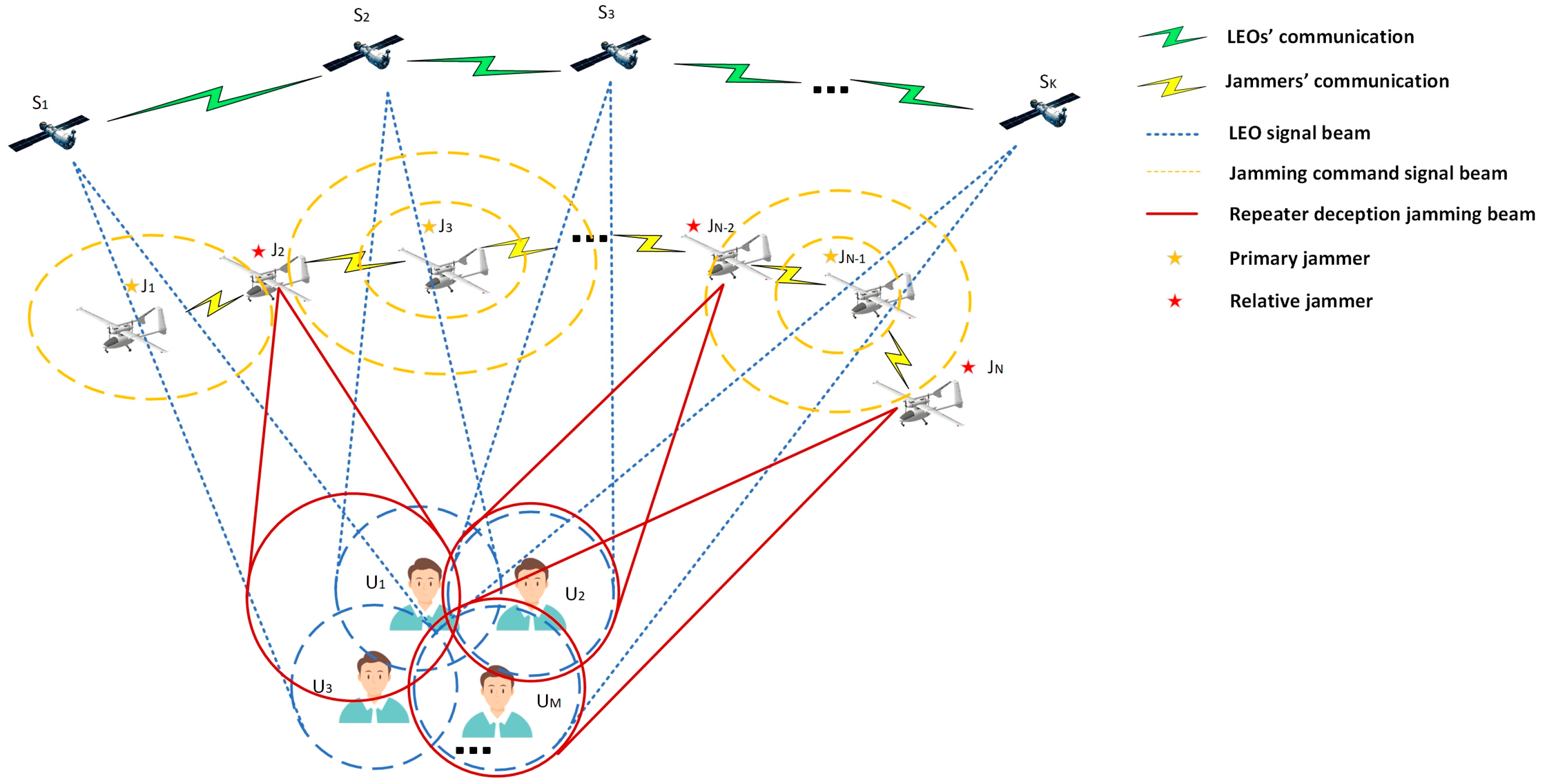
  • In this study, a distributed and collaborative LEO satellite jamming architecture with jammers is established to meet the fast, time-varying demand for LEO satellite signal jamming.
  • In this study, we propose a multi-dimensional adaptive optimisation method based on a hybrid game in the air–temporal–frequency–energy domain to achieve the optimal relative jammer allocation strategy under the Nash equilibrium for millisecond-level interference optimisation.
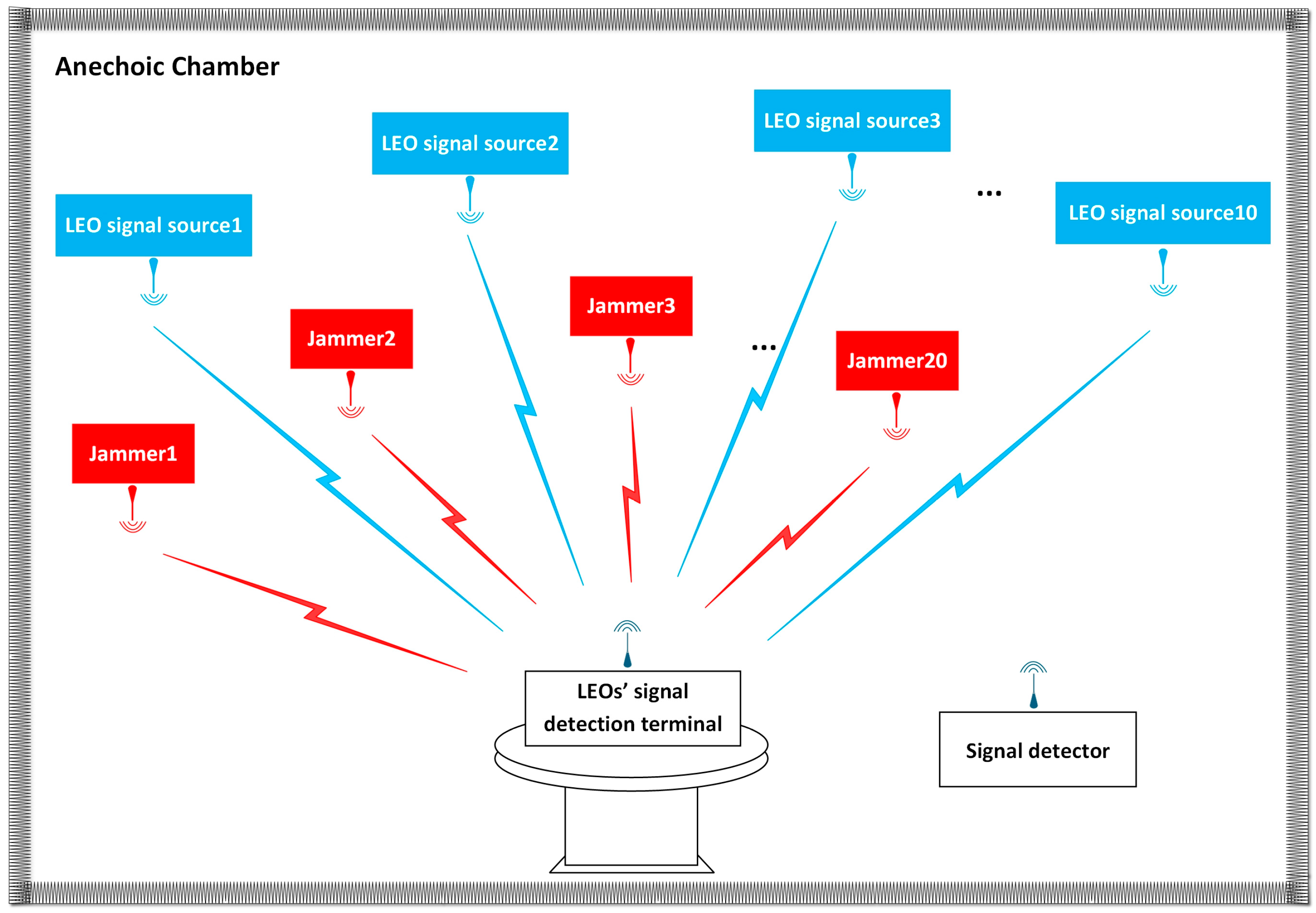
  • In this study, an LEO satellite interference verification system based on full-sky star fitting is constructed in a large microwave darkroom, and the verification of an LEO satellite multi-dimensional interference optimisation method based on hybrid game theory is completed. Compared with the existing interference optimisation methods, it has shown improvements in the BER and real-time response speed.
The rest of the article is organised as follows: Section 2 presents the related work on LEO satellite jamming techniques and optimisation methods, Section 3 describes the system model, Section 4 introduces the relative jammers screening algorithm, based on the hybrid game, and Section 5 presents the simulation verification and analysis. Section 6 is a summary of the whole paper.

2. Related Work

Research related to LEO navigation signal jamming is divided into four main categories: jamming methods, jammer deployment, jamming effectiveness assessment, and jamming station optimisation.
Jamming methods for LEO satellites are mainly categorised into blanket jamming and deception jamming [22]. Blanket jamming covers a wide range of areas, has a high success rate of jamming in the absence of countermeasures, and is able to further improve the performance of suppression jamming in terms of the form of the signal and the antenna from which the signal is transmitted [23,24]. In [25], constant modulus interference waveforms are efficiently generated with the help of CD algorithms in standard PREW scenarios, and precise blanket jamming is performed on specific targets by energy focusing. However, blanket jamming is less stealthy and easily interferes with our equipment. Deception jamming is mainly classified into repeater deception jamming and generative deception jamming. Generative jamming directly generates spoofed signals similar to LEO signals, intrudes into enemy receivers, and directly changes their position information [26]. In [27], generative adversarial networks (CTGANs), Gaussian copulas, and variational autoencoders (VAEs) are utilised to generate synthetic jamming attacks from a widely used UAVs attack dataset. In [28], a novel traction strategy using traction codes is proposed to suppress some of the authentication signals and form the desired correlation peaks. Generative jamming is covert and efficient, but generative jamming needs to be based on the premise that the form of LEO signals is known, and the form of military LEO signals is strictly encrypted, which makes it difficult to obtain all the information from these signals. Repeater deception jamming works by receiving and processing the real signal and then forwarding it out with a delay, without needing to know all the information about the signal [29]. In [30], repeater deception jamming techniques for creating false locations, false times, and false speeds are theoretically demonstrated.
Jammer deployment is an effective means of countering anti-jamming techniques, such as adaptive zeroing and beamforming. In [31], a joint optimisation scheme for Aerial Reconfigurable Intelligent Surfaces (ARISs) deployment and passive beamforming is developed for the deployment of a single jammer. In [32], an innovative distributed jammer centre-of-mass localisation method based on clustered centre-of-mass convergence is proposed to achieve an accurate estimation of the number of distributed jammers. However, it is difficult to implement effective jamming of highly dynamic, narrow-beam LEO signals with conventional single- or multi-site jammer deployments.
Establishing a jamming effectiveness evaluation criterion is a prerequisite for performing jamming optimisation. A reasonable evaluation criterion enables the optimisation to converge quickly and achieve efficient and fast interference. In [33], based on the existing results of the evaluation of the effectiveness of navigation interference, an index system for the evaluation of the effectiveness of satellite navigation receivers is constructed from four levels. In [34], a new method based on Convolutional Neural Networks (CNNs) for spoofing interference evaluation is proposed. In [35], a distributed jammer full-area cooperative deployment method is proposed, and the evaluation of the deployment effects, such as maximum spoofing range, spoofing success rate, pseudo-range rate, and power control, are carried out.
Optimisation for distributed jammer deployment not only improves jamming effectiveness but also reduces unnecessary losses. In [36], the problem of targeted allocation of weapon targets for air defence operations was solved using dynamic programming. In [37], the nonlinear combinatorial optimisation problem for the dynamic combination of weapon resources and objective matching on different platforms is solved using the 0–1 integer programming method. However, in the face of a large number of distributed interference sources, a variety of interference targets, and rapid changes in the dynamics of LEO satellites, it is often difficult for such exact algorithms to quickly converge to an exact solution. Besides some exact algorithms, heuristic algorithms are often used for distributed optimisation problems. In [38], a jammer optimisation method based on the Pelican optimisation algorithm is proposed, but the method is prone to fall into local optima. In [39], an artificial bee colony-based jammer allocation algorithm is proposed, but the method is sensitive to the relevant parameter settings, and the accuracy of the results is limited. In [40], a fusion algorithm based on Ant Colony and Q-Learning (Ant-QL), which does not rely on a priori information and enhances adaptability through real-time interaction between the jammer and the target radar, is proposed, but the method has a slow convergence speed, which is not able to meet the real-time requirements on the battlefield. In [41], an evolutionary reinforcement learning-based collaborative jamming resource allocation method is proposed, which uses joint multi-domain information to accomplish the optimisation of the joint allocation of jamming beams and jamming power under the constraint of jamming resources. In [42], a two-stage approach based on cooperative game theory is proposed to efficiently determine the optimal location and size of distributed energy sources to maximise their potential benefits. In [43], a multi-objective microgrid optimal arithmetic problem with different equations and inequality constraints is presented, and the optimisation of this distributed system is carried out using cooperative games. Currently, there are fewer studies on distributed interference optimisation problems using game-based approaches, and this study conducts a related study to fill this gap.

3. Distributed Jamming System Model for LEO Signal

3.1. Distributed Interference Scenario

The distributed interference scenario model is shown in Figure 1, illustrating a jamming scenario consisting of an LEO satellite, a jamming target, and a distributed UAV jamming station. LEO satellites use spot beams to transmit signals at different frequency points to communicate with users, a method that achieves an effective isolation of users in spatial and frequency domains while preventing crosstalk on the same frequency. The position of the LEO is marked as S k . Given the fast speed of LEOs and the requirement of real-time interference, S k only indicates the LEO locations used to serve the corresponding area during the communication timeframe. The point beam emitted by the LEO is denoted by L k . The jamming target at a specific range is located below the jamming source, and its position is labelled as U m . Each jamming target can receive multiple LEO signals and maintain a 1-way or 2-way communication link. The jamming target receives and decodes the navigation information from the LEO signals. In the downlink transmission process of the LEO star communication system, the communication mode of gaze is commonly used between the LEO star beam and the ground user terminal. The jamming targets receive the LEO’s narrow-beam signals through a multi-antenna transceiver system to enhance the reliability and capacity of the communication, and at the same time, it can well suppress interference from other directions. Therefore, by piggybacking the cluster jammers between the LEO star and the target to be jammed, the jamming effect can be significantly improved. The jammer’s position is labelled as J i . Distributed jammers are able to implement full coverage of star signal reception in the jamming area with the distribution of satellite positions for that time period and are capable of small positional movements. When the beam of an LEO passes through the movable area of the jammer under that time period, the jamming system is considered to be able to pick up the LEO signal and strike the corresponding jamming target effectively. To ensure that strategic jamming is implemented instantly, a division of labour between the jammers is required. Jammers are classified as primary and relative jammers. The locations of the primary and relative jammers are noted as J i P and J i R , respectively. The primary jammers have a high processing capacity and only complete the reception and processing of one LEO signal. The relative jammers enable the broadcast of multiple LEO signals. For a distributed jammer model, each jammer can be either a primary or a relative jammer.

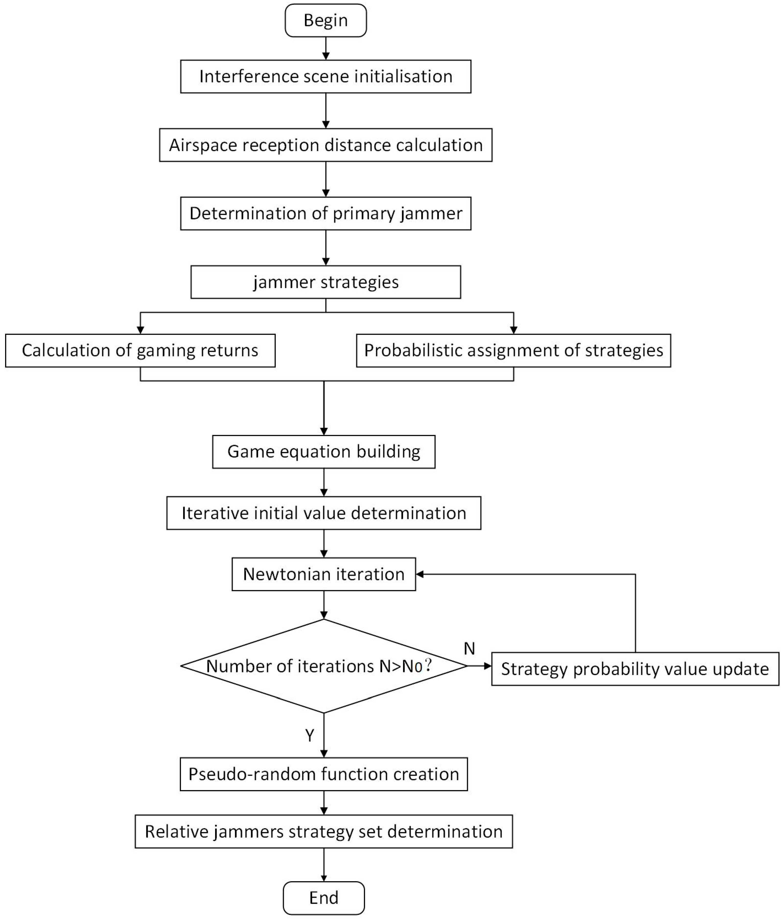
3.2. Distributed Interference Optimisation Implementation Process

In order to optimise the jamming effectiveness, multi-dimensional strategies in the air, time, frequency, and power domains need to be considered to ensure that multiple jammers can achieve efficient co-operation. Figure 2 represents the block diagram of the distributed interference optimisation algorithm flow. In the spatial domain, dynamic determination of the primary and relative jammers is achieved by calculating the minimum reception distance of the corresponding LEO satellite. The primary jammers perform a hybrid decision game to determine the set of secondary jamming source strategies to be used for relaying LEO satellite jamming signals. The multi-dimensional information optimisation method is used to construct the strategy payoff function by combining information from the time, frequency, and power domains. Assigning an unknown probability to each strategy, such that the expected payoffs from all primary sources of interference are equal, constructs the game equation. The equation is solved with the help of the mathematical iterative method to obtain the probability value of the strategy when the number of iterations is greater than N 0 . This strategy probability corresponds to a Nash equilibrium point. The pseudo-random algorithm is constructed by strategy probability.
Each primary jammer plays the game several times, with the help of a pseudo-random algorithm, to filter out the optimal set of relative jammer strategies under the Nash equilibrium. The primary jammer receives the LEO signals from the area to be jammed and processes the signals, including down-conversion, code stream extraction, etc., modulates them into a special frequency band, and broadcasts them to the relative jammers. The relative jammers receive the jamming command and jamming LEO information from the primary jammers, adds time delay and up-conversion to the signal, and then broadcasts it to the jamming target through the directional antenna to complete the jamming of the jamming target.

3.3. Identification of Primary and Relative Jammers

When jamming the jamming target, the distributed jamming system will operate adaptively according to the current environmental situation and complete the early interception and forwarding jamming of the LEO signals. LEO satellites use narrow-beam signal transmission, and the coverage probability is inversely proportional to the satellite density, orbital angle, and orbital altitude [44]. In the literature [45], the downlink signal antenna reception is analysed using airborne jammers at different altitudes moving parallel to the LEO satellite, illustrating that the relative angular difference is more important in the jamming-to-original-signal ratio than the distance between the ground station and the jammer or the satellite, confirming that the jamming-to-original-signal ratio increases as the relative angular difference decreases. Therefore, combined with the electromagnetic characteristics of LEO signals, the interference source is dynamically bisected by simplifying the calculation of the relative angular difference to complete the jammers. As shown in Figure 3, the primary jammer needs to receive the LEO signals for the first time, so the jammer with the smallest reception distance in the airspace should be selected as the primary jammer. Other jammers that are further away from the centreline of the beam are identified as relative jammers.
The primary jammer is determined according to Equation (1).
d i , k = ( J i S k ) × L k L k      ,      i P = a r g   m i n   ( d i , k )
where d i , k is the distance of each jammer from the beam, L k is the k t h LEO beam, a r g   m i n   ( d i , k ) is the corresponding jammer subscript i closest to the k t h LEO satellite beam, and J i P is the primary jamming source.

4. Relative Jammer Screening Algorithm Based on Mixed-Strategy Game

4.1. Primary Jammer Set and Strategy Set

The distributed primary jammer J i P is the player involved in the relative jammer allocation game. J i P denote the primary jammers, other than the i P t h primary jammer. The strategy of the i P t h primary jammer is X i P , which refers to the vector of feasible strategies that the primary jammer may adopt. The full set of strategies, S i = ( X 1 , X 2 , , X N ) for all N primary jammers, is called an overall strategy combination. The set of strategies S i formed by the primary jammer is the Cartesian product of the strategies X i P of each primary jammer.
For the i P t h primary jammer, one of the strategies made by it, X i P , may consist of K optional relative jammers, as shown in Equation (2).
X i P = [ x 1 i P , x 2 i P , x 3 i P , , x K i P ] T          o = { 0 , 1 }
where x k i P is whether the k t h relative jammer is selected as the interference signal forwarding carrier, 0 indicates no selection, and 1 indicates a selection. The constraint is k = 0 K x k i P 1 , i.e., each primary jammer selects at least one relative jammer as an interference signal forwarding carrier.

4.2. Multidimensional Utility Function Construction

The factors considered for interference optimisation include three factors: time, power, and frequency. The algorithm needs to map the lost time, lost power, and Doppler shift into the utility function. The utility function is a measure of the overall interference effect or the strength of the strategy. By observing the utility function values, it is possible to understand more intuitively the impact of each primary jammer on the overall interference effect after the game.
As shown in Equation (3), in order to fuse the parameters of the different domains into the utility function, the time loss τ i P , i R , power loss W i P , i R , and Doppler shift loss f i P , i R are normalised for the i P t h primary jammer, using the i R t h relative jammer for forwarding.
τ i P , i R = | τ i P , i R τ i P   m i n | | τ i P   m a x τ i P m i n | W i P , i R = | W i P , i R W i P   m i n | | W i P   m a x W i P   m i n | f i P , i R = | f i P , i R f i P   m i n | | f i P   m a x f i P   m i n |
where τ i P , i R is the normalised forwarding delay, τ i P   m i n and τ i P   m a x are the minimum forwarding delay and maximum forwarding delay, respectively, for a primary jammer using a relative jammer for spoofing. W i P , i R is the normalised power loss, W i P   m i n and W i P   m a x are the minimum and maximum power loss, respectively, for a primary jammer using a relative jammer for deception. f i P , i R is the normalised frequency shift, and f i P   m i n and f i P   m a x are the minimum and maximum frequency shifts, respectively, for a primary jammer using a relative jammer for spoofing.
As shown in Equation (4), the utility function brought about by the i P t h primary jammer, using the i R t h relative jammer for signal forwarding, is P i P , i R .
P i P , i R ( x i R i P ) = ( A · τ i P , i R + B · W i P , i R + C · f i P , i R + D i P = 0 N P x i R i P ) x i R i P
where A , B , and C are the time loss, power loss, and frequency loss weighting factors, respectively. ( A · τ i P , i R + B · W i P , i R + C · f i P , i R ) x i R i P is the expenditures resulting from the decisions taken regarding the time, power, and frequency. D denotes the fixed efficacy gain from each relative jammer. If D is small, it results in a negative gain and the search for available relative jammers is not possible. The primary jammers will share equally the gain from a relative jammer, in relation to the overall decision. i P = 0 N P x i R i P is the number of times a relative jammer has been selected at a given moment. The selection of a particular relative jammer by too many primary jammers can lead to a reduction in D i P = 0 N P x i R i P . The total utility function P i P for each primary interference source is P i P , i R summed over i R . In scenarios where the real-time requirements of jamming are quite high, the system considers increasing the weight A of the forwarding delay appropriately to increase the impact of time on the jamming effect. The value of A is also related to factors such as propagation path differences, jammer processing delays, and time synchronisation accuracy. In the case of low ambient signal-to-noise ratio, the power factor B is appropriately increased to improve the interference effectiveness. We focus on the effect of the Doppler shift on the specific gravity C, when the target to be jammed is moving rapidly relative to the LEO and the jammer. The value of D, as a jammer performance parameter, should be a fixed value. In engineering realisation, when the number of main interference sources is 5, the value of D is taken as 20. The engineering empirical values of weights A, B, and C, with respect to the signal-to-noise ratio (SNR) and the ratio of the velocity of the target to be jammed to the magnitude of the jammer’s velocity (VR), are given in Table 1. We subsequently consider a large number of experimental data to fit the appropriate coefficients for different scenarios, in order to achieve adaptive adjustment.
The Nash equilibrium of a mixed-strategy set for the N-player non-cooperative game is S = ( X 1 , X 2 , , X N ) , i.e., let P i P ( S | | x i R i P ) P i P ( S i ) hold. For any primary jammer, an arbitrary change in its decision variables cannot lead to an increase in its effectiveness, i.e., the game reaches the Nash equilibrium point, provided that the strategies of the other sources of interference remain unchanged.
(1)
Forwarding interference time loss model
The time-delay principle of the distributed jamming system is that the relative jammer receives all currently available satellite signals, time-delays them separately, and then broadcasts the combined spoofed signals to the target to be jammed. When the correlation peak of the spoofed signal is higher than the true signal, the tracking loop of the target receiver can be made to lock on to the spoofed signal and produce an erroneous position solution.
The signal from the LEOs is transmitted to the primary jamming source to receive, process, and forward to the secondary jamming source, which receives the jamming information from the primary jamming source and forwards the k t h LEO satellite signal to the m t h user as the target to be jammed. The calculated pseudo-range of the interfering signal, when it reaches the target receiver, is shown in Equation (5).
ρ 1 = J i P S k + J i M J i R + U m J i R + c · ( τ M V + δ m + τ k m )
where J i P is the position of the i P t h primary jammer, S k is the position of the k t h LEO satellite, J i R is the position of the i R t h relative, U m is the desired spoofing position of the m t h user, τ M V is the processing delay of the jammer, c is the speed of light, δ m denotes the reception clock difference of the m t h user, and τ k m is the m t h user’s signal processing of the k t h LEO satellite delay.
The actual signal arrives at the user’s calculated pseudo-distance, as shown in Equation (6).
ρ 2 = U m S k + δ m · c
The time loss is shown in Equation (7).
τ L O S S = ρ 1 ρ 2 c
(2)
Interference power loss model
The power loss is mainly caused by the path attenuation, and the power loss will be compensated to some extent due to the antenna gain, as shown in Equation (8).
W L o s s = 10 ^ [ ( P t L M , V + G t / r   ) / 10 ] 10 ^ ( P t / 10 )      L M / V = 32.44 + 20 l g ( f M , V ) + 20 l g ( d M , V ) G t / r = 10 l g [ 4.5 ( D λ ) 2 ]       
where W L o s s is the power loss, P t is the transmit power, L M , V is the loss of the signal in free space, divided into the frequency of forwarding from the primary jammer to the relative jammer and the power loss of forwarding the spoofed signal from the relative jammer to the target receiver, G t is the transmit antenna gain, G r is the gain of the receive antenna, f M , V is the frequency of the signal being forwarded from the primary jammer to the relative jammer and the relative jammer frequency forwarded to the target, d M , V is the distance the signal travelled in free space, D is the parabolic diameter of the antenna, and λ is the wavelength of the transmitted signal.
(3)
Doppler shift loss mode
Interfering target receivers down-convert and pass through bandpass filtering when receiving signals, thus requiring that the interfering signal be within the frequency band. The main factor affecting the frequency variation is the Doppler shift, and Doppler compensation is required before the implementation of an interfering signal transmission.
The positions of the LEO satellite, the relative jammer, and the target to be jammed are S k , J i R , U m , and the velocities are v k S , v i R J , v m U , respectively. The Doppler shift of the real signal arriving at the target receiver is shown in Equation (9).
f 0 = A 0 f 0 A 0 = ( v k S v m U ) · ( U m S k ) U m S k c
where f 0 is the LEO satellite signal transmission frequency, and the frequency at which the jamming target receives a particular LEO satellite signal is f 0 + f 0 .
The Doppler shift at which the spoofed signal emitted by the relative jammer reaches the target receiver is shown in Equation (10).
f 1 = A 1 f 1 A 1 = ( v i R J v m U ) · ( U m J i R ) U m J i R · c
where f 1 is the relative jammer transmitting frequency, and the frequency at which the jamming target receives the jamming signal emitted by a relative jammer is f 1 + f 1 .
By making f 1 + f 1 = f 0 + f 0 , the emission frequency can be calculated, as shown in Equation (11).
f 1 = 1 + A 0 1 + A 1 · f 0
The Doppler shift compensation f to be performed relative to the satellite launch frequency f 0 is shown in Equation (12).
f = A 0 A 1 1 + A 1 · f 0

4.3. Nash Equilibrium Point Solution

The primary jammer evaluates the system gains using the constructed utility function. All primary jammers play a hybrid game for resource allocation optimisation. Solving the Nash equilibrium under mixed strategies requires assigning a probability to each pure strategy. A pure strategy X i P for the i P t h primary jammer is selected with the probability p i P = { p 1 i P , p 2 i P , , p K i P } , where p k i P 0 , k = 1 K p k i P = 1 should be satisfied.
Given the strategy formula G = { N , { X i P } , { p k i P } } and the mixed-strategy outcome { p 1 , p 2 , , p K } p i P , the expected value of the return obtained in the mixed-strategy situation selected by the i P t h primary jammer is shown in (13).
E ( P k i P ) = x X p i P ( x ) P i P ( x ) = x = { x 1 , x 2 , , x K } X p 1 ( x 1 ) · p 2 ( x 2 ) · · p K ( x K ) P i P ( x )
The probabilistic equation for the game decision is established based on the fact that all decisions have the same expected return, along with the equation k = 1 K p k i P = 1 . This system of multivariate nonlinear equations is solved with the help of Newton’s iterative method to obtain the corresponding situation probability p i P . The initial value of the Newton iteration needs to satisfy ( 0 , 1 ] , the iteration threshold to be set to 55, and the convergence condition to be m a x ( x i m x i m 1 ) 10 3 .
The existence of Nash equilibrium points for the mixed game requires the help of Kakutani Shizuo’s immovable point theorem. The mixed-strategy probability space can be expressed as Equation (14).
i P = p i P R S i P | p i P ( x ) 0 , x S i P p i P ( x ) = 1
From Equation (14), each i P is a simplex. The overall strategy probability space is = 1 × 2 × × n , which is tight and convex. Since the utility function is continuous, the optimal response varies continuously with the decisions of the other primary jammers. Thus, optimal responses are upper semicontinuous. An optimal response is the set of strategies that maximise expected utility, and the set of solutions for maximising the linear function on a convex set is convex. It follows from Kakutani Shizuo’s theorem that there exists an optimal response of each primary jammer to the other jammers, i.e., a Nash equilibrium point exists.
Each primary jammer builds a pseudo-random function using the solved strategy probabilities. Each primary jammer independently selects their strategies with the help of a pseudo-random function, and the corresponding combination of strategies serves as the optimal set of strategies under the Nash equilibrium. In order to minimise the effect of randomness, a pseudo-random function will be used several times to obtain the strategies, and the set of strategies with the highest number of occurrences will be used as the set of relative jammers.

5. Simulation and Analysis

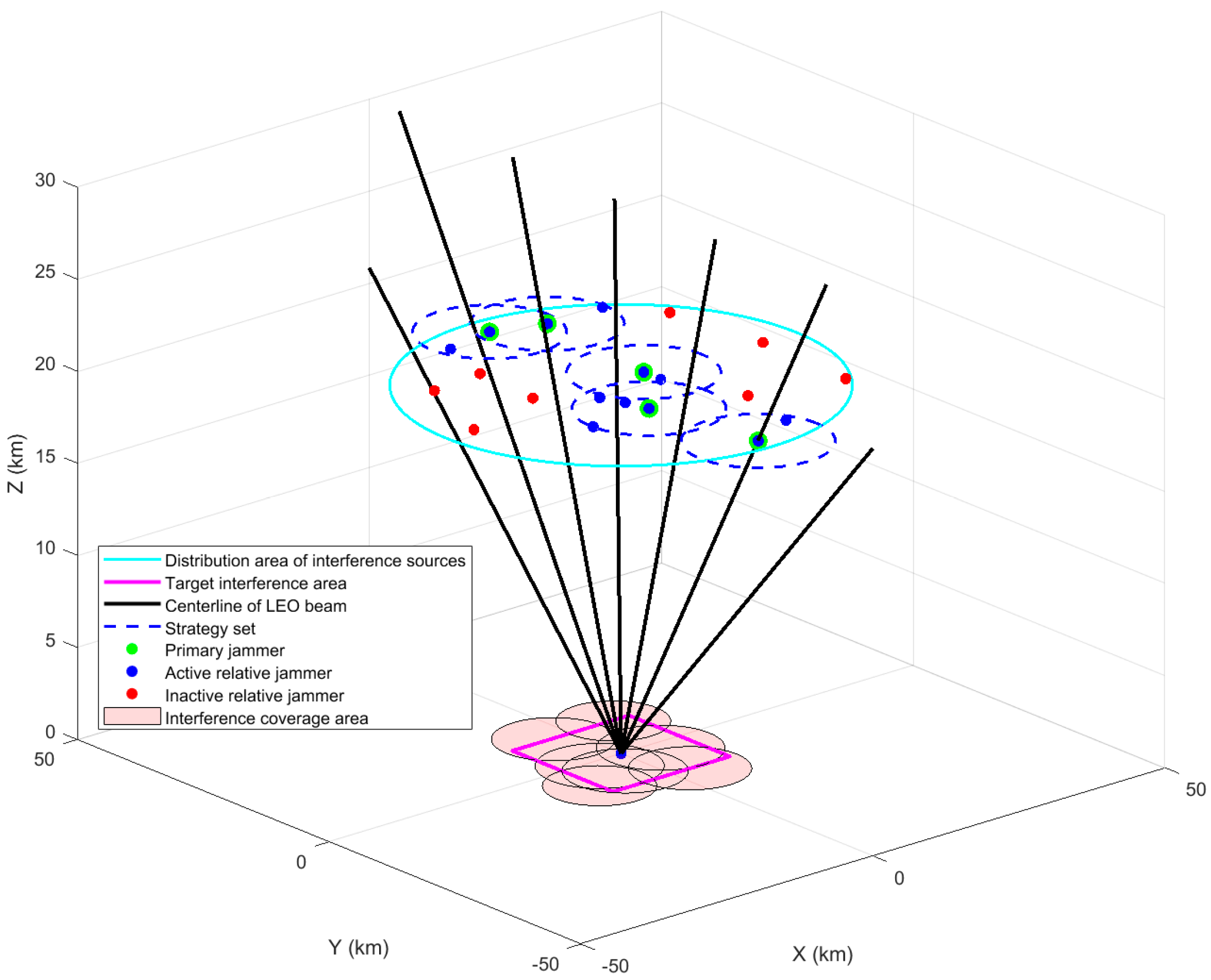
5.1. Interference Verification Scenario

As shown in Figure 4, the simulation uses GIS to establish a low-orbit megastar seat interference countermeasure scenario, with a large microwave darkroom as the interference verification scenario. Figure 5 represents the equipment layout. Highly dynamic LEO satellite constellations show different distributions over time. A number of jammers are distributed at a certain height above the area to be disturbed. All distributed jammers can communicate with other distributed jammers, and an LEO signal receiving terminal is placed at the centre of the jamming area.
The distributed interference simulation model is shown in Figure 6. The primary and relative jammers are divided from the airspace. The five primary jammers receive the corresponding LEO satellite signals and then engage in a mixing game. The Nash equilibrium solution, i.e., the set of sub-interference source strategies, is solved. Broadcast LEO signal information and jamming commands to the corresponding relative jammers. Relative jammers complete the interference coverage of the area.
In order to verify the feasibility of the method, the simulation is completed to verify the jamming effectiveness of the distributed jammers of the same topology in different scenarios, and of the different topologies in the same scenario. Information such as the BER and interference signal coverage is analysed. The proposed algorithm is compared with the gradient descent algorithm (GD), dynamic programming algorithm (DP), and genetic algorithm (GA) to verify the performance of the proposed algorithm.

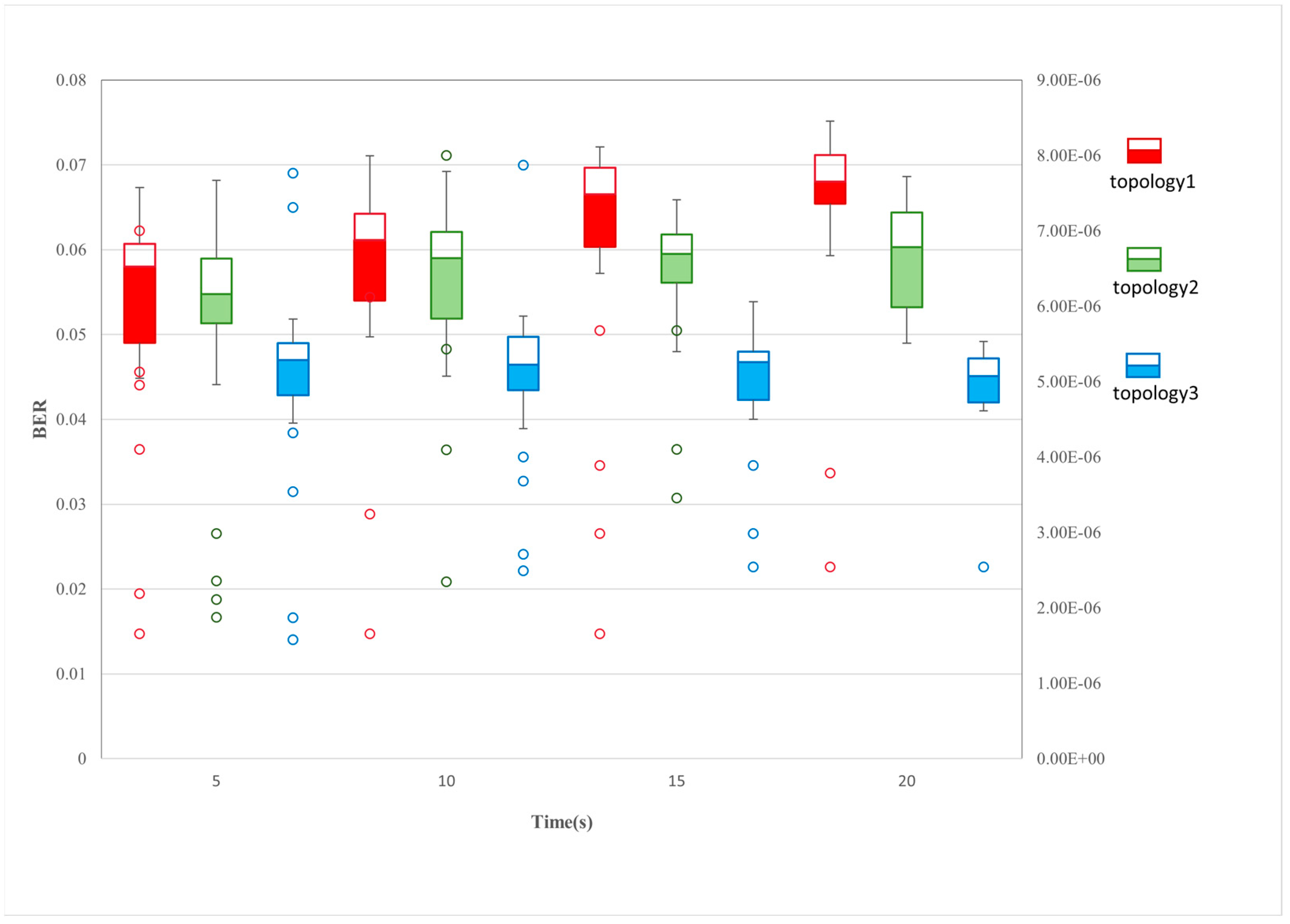
5.2. Distributed Jammers of Same Topology in Different Scenarios

The topology of a set of distributed jammers is obtained using a distributed inference algorithm. Simulations verify the feasibility and effectiveness of the proposed distributed interference optimisation strategy in this topology.
Figure 7 shows the interference scenarios and the corresponding set of game strategies for the distributed interference sources at moments t1 and t2 in the same topology. At the moment t1, the BERs of the LEO signals received by the jamming target receiver are 5.53 × 10 2 , 8.71 × 10 2 , 3.42 × 10 2 , from left to right. At the moment t2, four LEO satellite signals need to be jammed. The BERs of the LEO star signals received by the receiver are 3.87 × 10 2 , 4.72 × 10 2 , 5.32 × 10 2 , 6.42 × 10 2 , from left to right. Low-orbit satellite signals are received with a BER on the order of 10 2 . From the BER point of view, it can be seen that the model has good interference effectiveness and the receivers in this region are not able to successfully decode the valid data.
Figure 8 represents the regional interference coverage for the two scenarios. When the jamming signal does not achieve full area coverage, the distributed jamming source increases the power of the appropriate jamming signal to achieve a full-range area strike. The jamming system demonstrates a strong jamming coverage capability. It is not only able to achieve the basic one-layer coverage with enhanced two-layer coverage effect but also has the potential to accomplish three-layer or even multiple-layer coverage. This multi-layered interference greatly enhances the strength and effectiveness of the interference, causing greater obstruction to the normal decoding and information extraction at the receiver.
In the scenario at the moment t1, the main interference source game solves for the Nash equilibrium point, corresponding to utility function values of 3.2872 , 3.1349 , and 2.9372 , from left to right. In the scenario at the moment t2, the utility function values corresponding to the Nash equilibrium points are solved by each main interference source through the game, from left to right, as 3.2317 , 3.5121 , 3.6391 , and 3.4317 .
As can be seen in Figure 9, this topology is able to converge in terms of time-averaged coverage of the interference region after using the proposed optimisation method. The one-fold coverage converges to 100%; the two-fold coverage converges to 50.3588%; and the three-fold and above coverage finally converges to 20.7062%. This result shows that the interfering signal can effectively achieve full coverage in the whole domain range and can use less optimisation time to complete the stable coverage effect, which improves the interfering efficiency.
Figure 10 represents the variation curve of the BER of the jamming target receiver during the process of the jammers going from off to on to off. When the jammers are not turned on, the BER is on the order of 10 6 , indicating that the system is able to achieve normal communication and positioning. When the jammers are turned on, the BER is stably distributed between 3 × 10 2 and 7 × 10 2 . Effective jamming is achieved, and the quality of the communication link decreases significantly. In the absence of jamming, the signal receiver receives a signal with a BER mean of 5.259 × 10 6 , a sample standard deviation of 1.185 × 10 6 , and an overall standard deviation of 1.182 × 10 6 . This demonstrates that more stable communication and data transmission can be accomplished between the analogue source and the signal receiver of the LEO star when no interference is carried out. When jamming is performed, the signal receiver receives a signal with a BER mean of 5.331 × 10 2 , a sample standard deviation of 4.522 × 10 3 and an overall standard deviation of 4.417 × 10 3 . This demonstrates the effectiveness and high success rate of jamming while enabling stable jamming.

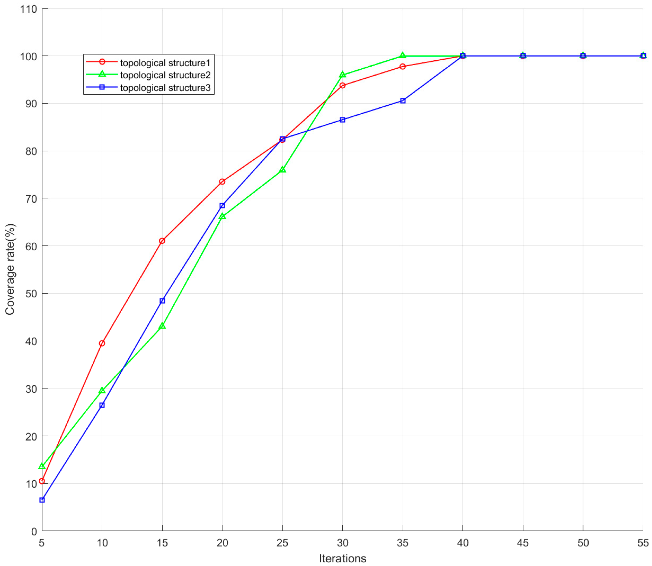
5.3. Distributed Jammers in Different Topologies

In order to verify the feasibility of optimising the interference effect, the interference of distributed interference sources in different topologies should be analysed. Two groups of three randomly generated and uniformly distributed topologies are selected, denoted as topology 1, topology 2, and topology 3, and the number of LEO satellites to be interfered with is 7.
As shown in Figure 11, the boxplots record the BERs for 100 experiments for three different topologies, with jamming implemented for 5 s, 10 s, 15 s, and 20 s. The red, green, and blue boxes represent data for topologies 1, 2, and 3, respectively. The tight distribution of the upper and lower edges of the box-and-line plots shows that the jamming system maintains decision stability even when the distributed jammers are presented with different topologies. This provides some technical guarantee for the future realisation of highly dynamic airborne jammers. The nonlinear growth of the median line in the box with the times indicates that the system has a certain perception capability. Under the premise of ensuring interference stability, the system implements progressive interference regulation through dynamic parameter optimisation and strategy iteration mechanisms, which ultimately achieve a stepwise increase in interference effect. This adaptive regulation not only maintains the basic stability of the suppression effect but also achieves a cumulative enhancement in the interference gains through continuous strategy evolution. The hollow circles are the singular values appearing in the box plots, and the axes are on the right side, indicating the number of unsuccessful interference realisations. It can be seen that as the jamming time increases, the singular values become less and the jamming success rate increases.
As shown in Figure 12, with the accumulation of the number of iterations of the game, the one-weight coverage for the jamming region shows a gradual increase and eventually tends to converge stably. With the deepening of the game process, the jamming system gradually optimises its effectiveness, and finally achieves a stable one-weight coverage state.

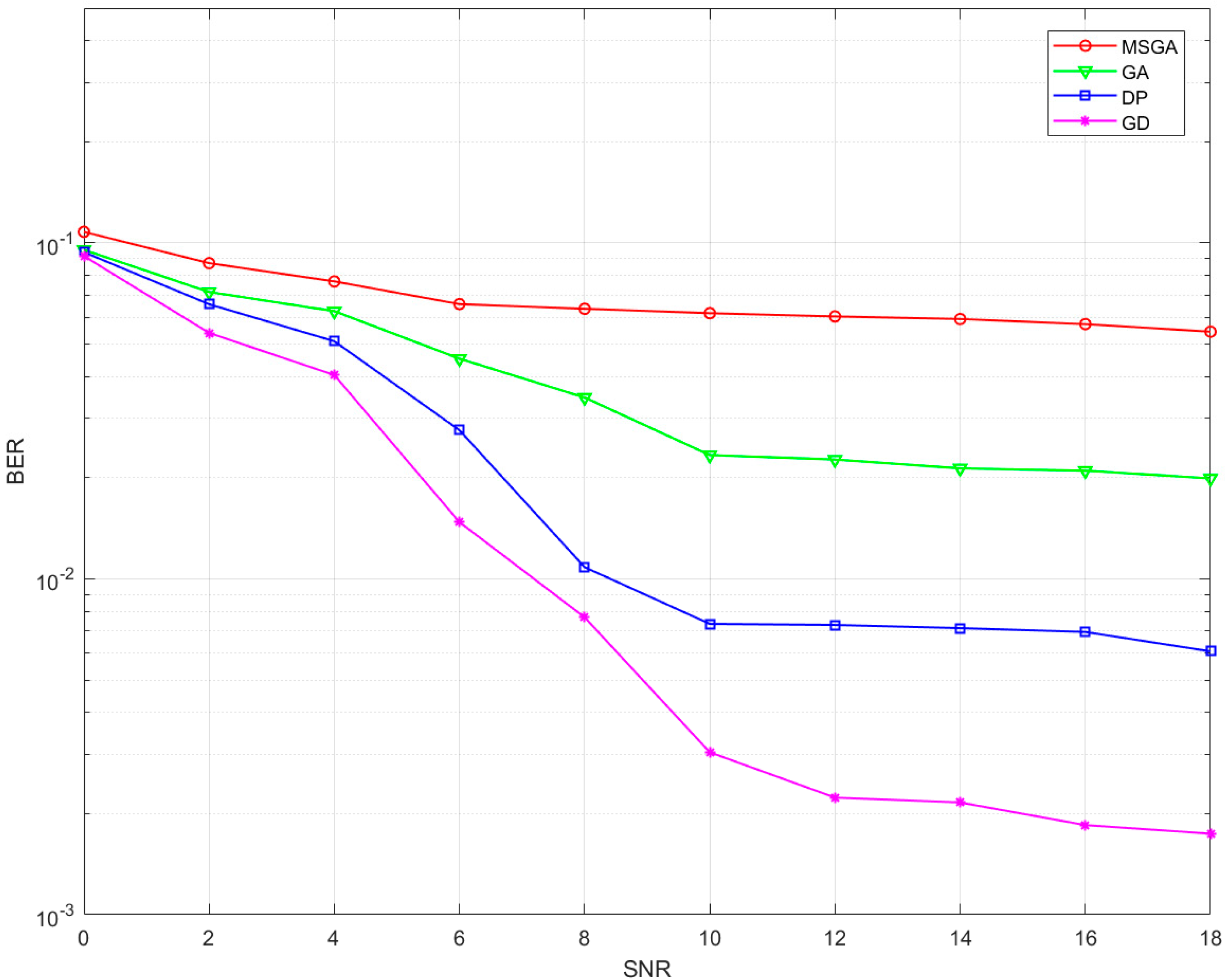
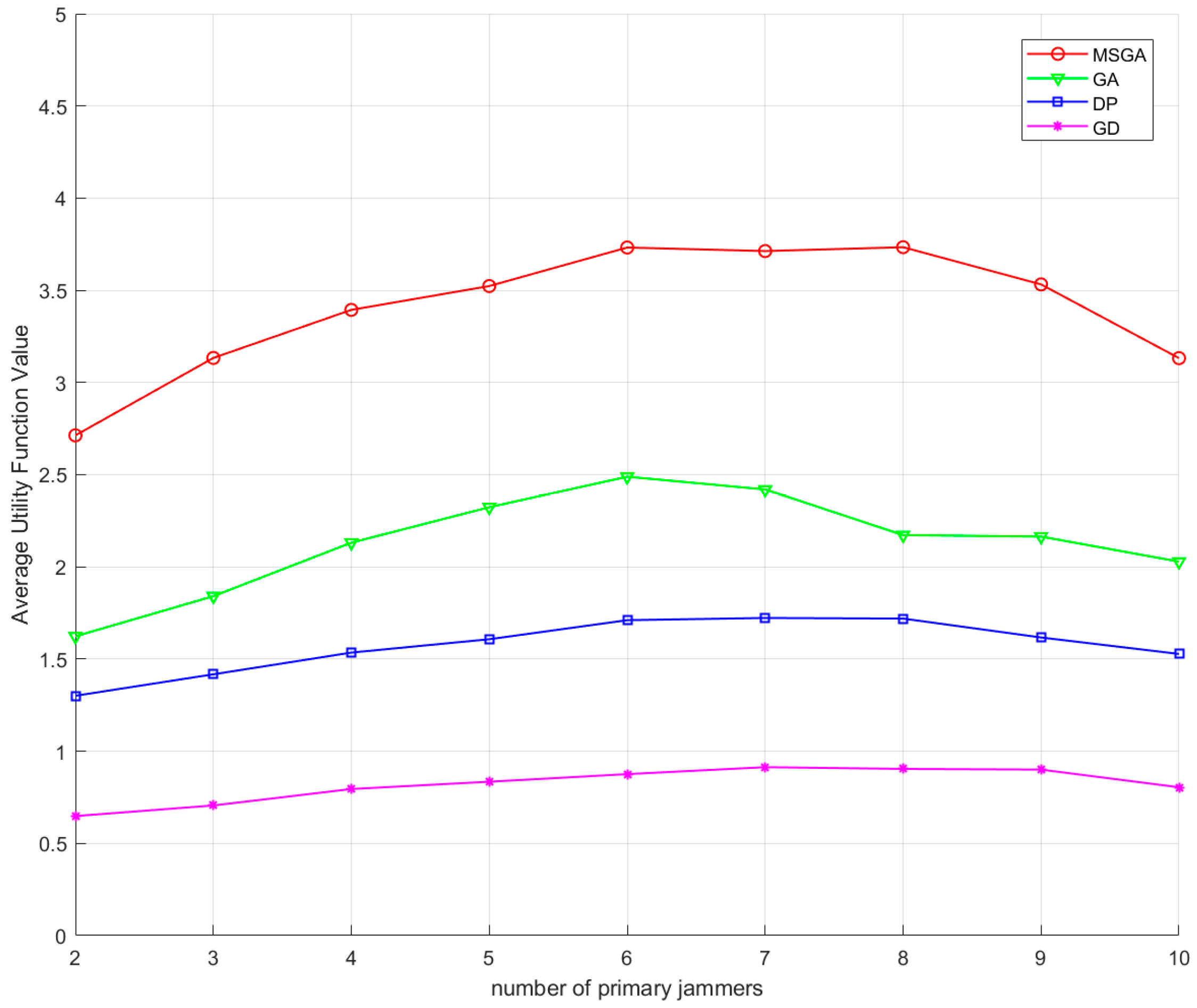
5.4. Comparison of Methods

In the field of discrete optimisation, representative optimisation algorithms include gradient descent algorithm (GD), dynamic programming algorithm (DP), and genetic algorithm (GA). The set of strategies corresponding to the primary jammers is obtained by the above three algorithms, and the performance of the optimisation algorithm proposed in this paper is verified by comparing the utility function values and BERs with those of the algorithm.
The relevant parameters of the comparison algorithm are set as follows: (1) GD: the learning rate set to 0.03, the number of iterations to 350, the momentum term to 0.8, the L2 regularisation factor to 10 3 , and the decision change stopping threshold to 10 3 . (2) DP: the resource quantity is set to 110, the resource discretisation slot is 10, and the pruning threshold is 100. (3) GA: the coding method is binary, with a population size of 90, a crossover probability of 0.8, a variance probability of 0.02, and an elite retention of 3.
Table 2 represents a comparison of the performance of the methods. From the point of view of time complexity, the proposed algorithm and the GD algorithm have the lowest time complexity, and the DP algorithm has the highest. From the point of view of interference success rate, the proposed algorithm in this paper has the highest success rate and the GD algorithm has the lowest success rate. The GA algorithm solution quality is close to the global optimum, but its dependence on parameter tuning is strong. Meanwhile, GA algorithms are good at global exploration but lack fine-grained local search capability, which greatly increases unnecessary repeated computations. The DP algorithm also achieves a high success rate, but its computation of the exact solution consumes a large amount of time and computational resources, which makes it unable to satisfy the real-time requirements of the jamming scenarios. The GD algorithm, on the other hand, tends to fall into the local optimum, and it is not able to achieve stable and successful jamming, although it achieves an efficient computation in terms of time. In addition, saddle points with gradients close to zero are more common than local minima in high-dimensional spaces, where gradient descent may stall, which can lead to interference failures from time to time.
In this study, the BER variation rule with the signal-to-noise ratio (SNR) of the four optimisation methods is demonstrated in Figure 13 under the scenario that the forwarded interference signal intrudes into the receiver. The experimental results show that in the low SNR region (SNR < 8 dB), the system BER is mainly dominated by the environmental noise, and at this time, the performance difference between the anti-jamming algorithms does not show significant differentiation. When the SNR is increased to more than 10 dB, the influence of environmental noise shows an exponential decay trend. At this time, the forwarding interference signal becomes the core factor restricting the BER, and the performance difference of the algorithms starts to appear significantly. The retransmitted interference signal can break through the limitation of the traditional filter and penetrate into the demodulation module at the receiver. It is worth noting that the optimisation algorithm proposed in this study shows a significant advantage in the 12–18 dB high SNR interval, which can control the BER stably at 6 × 10 2 , while the GD algorithm has a lower BER in this interval, which verifies its lack of interference capability.
Figure 14 shows the values of the interference mean utility function under different optimisation methods. It can be seen that the interference mean utility functions of all the methods show a tendency of increasing and then decreasing. This phenomenon can be attributed to the effect of the variation in the number of primary jammers on the interference gains. As the number of primary jammers increases, the jamming gain increases significantly. Due to the constant number of total jammers, when the primary jammers account for a large proportion, the number of available relative jammers decreases accordingly, which forces some of the primary jammers to have to choose the relative jammers with lower gains, which leads to a decrease in the overall utility value. From the utility function point of view, the utility function values of the algorithms in this paper are higher than the other three methods for different numbers of primary jammers. Compared to the GA algorithm, the utility function value of the proposed algorithm in this paper is improved by a maximum of 0.7187 times when the number of primary jammers is 8, and a minimum of 0.4993 times when the number of primary jammers is 6. Compared to the DP algorithm, the utility function value of the proposed algorithm in this paper is improved by a maximum of 1.2110 times when the number of primary jammers is 4, and a minimum of 1.0502 times when the number of primary jammers is 10. Compared to the GD algorithm, the proposed algorithm in this paper improves the utility function value by a maximum of 3.4386 times when the number of primary jammers is 3, and a minimum of 2.8927 times when the number of primary jammers is 10.

6. Conclusions

This study aims to prevent the enemy from taking advantage of the low latency and high transmission rate characteristics of LEOs in the battlefield to obtain information advantages and carry out precise strikes against their opposition. In this study, a distributed dynamic interference scenario in the LEO region is built, the jammers are divided into two categories of primary and relative jammers based on airspace characteristics, the interference effectiveness evaluation functions including time, frequency, and power domains is established, and a multi-dimensional interference optimisation method based on hybrid game theory for LEO satellite signals is proposed. Field interference tests are conducted in a large microwave darkroom at the Xi’an Research Institute in China, and the efficiency of the algorithm is verified by comparing it with the GA algorithm, the DP algorithm, and the GD algorithm, taking into account factors such as the BER, the interference coverage, the value of the utility function, and the Nash equilibrium for the set of strategies. The simulation verifies that the proposed algorithm is able to achieve multiple area coverage, while the utility function value and the BER are significantly better than the other three algorithms, which optimises the distributed jamming resource allocation and improves the jamming efficiency and success rate. The method proposed in this paper has certain application value and development prospects in future military and civilian fields. However, the engineering limitation of this method is mainly that the utility function cannot be adjusted in real time for a dynamic environment. In the future, we will consider using neural network (e.g., transformer, etc.) tools to achieve adaptive tuning of utility functions to meet the demands of interference in different environments, as well as exploring distributed interference optimisation methods.

Author Contributions

Conceptualisation, C.T. and X.Z.; methodology, C.T.; software, X.Z.; validation, C.T., L.Z. and Y.L. formal analysis, L.Z.; investigation, C.T.; resources, L.Z.; data curation, X.Z.; writing—original draft preparation, X.Z.; writing—review and editing, L.Z.; visualisation, L.Z.; supervision, Z.D.; project administration, Z.D.; funding acquisition, C.T. and L.Z. All authors have read and agreed to the published version of the manuscript.

Funding

The authors would like to thank the editors for their rigorous work and the anonymous reviewers for their comments and suggestions. This work was supported in part by the National Natural Science Foundation of China under Grants 62171375, 62271397, 62173276, 62101458, 62001392, 61803310, and 61801394, and in part by the Shenzhen Science and Technology Innovation Program under Grant JCYJ20220530161615033.

Data Availability Statement

The raw data supporting the conclusions of this article will be made available by the authors on request. The data are not publicly available due to future experiments require the use of collected data.

Conflicts of Interest

The authors declare no conflicts of interest.

References

  1. Shayea, I.; El-Saleh, A.A.; Ergen, M.; Saoud, B.; Hartani, R.; Turan, D.; Kabbani, A. Integration of 5G, 6G and IoT with Low Earth Orbit (LEO) networks: Opportunity, challenges and future trends. Results Eng. 2024, 23, 102409. [Google Scholar] [CrossRef]
  2. Ge, Y.; Liu, Y.; Lyu, D.; Wu, M.; Wang, Y.; Cao, X.; Shen, F. LEO satellite clock modeling and its benefits for real-time LEO PPP timing. Measurement 2025, 242, 116035. [Google Scholar] [CrossRef]
  3. Klír, R.; Rozenberg, R.; Ďurčo, S. Celestial Navigation. In Proceedings of the International Multidisciplinary Scientific Geo Conference Surveying Geology and Mining Ecology Management, Albena, Bulgaria, 18–24 August 2020; pp. 311–318. [Google Scholar]
  4. She, H.; Huang, G.; Wang, L.; Qin, Z.; Xie, S.; Lai, W.; Tian, J. A simplified GNSS/LEO joint orbit determination method. Measurement 2024, 236, 115029. [Google Scholar] [CrossRef]
  5. Fang, J.; Tu, R.; Zhang, P.; Zhang, R.; Lu, X. UPDs estimation and ambiguity resolution performance evaluation of LEO navigation system. Adv. Space Res. 2024, 74, 2883–2900. [Google Scholar] [CrossRef]
  6. Wu, Z.; Jing, G.; Ding, J.; Zhao, X. SCMA-Q-learning with overload control for random access in LEO satellite mMTC networks. Phys. Commun. 2025, 69, 102584. [Google Scholar] [CrossRef]
  7. Chang, C.; Zhao, Q.; Li, M.; Li, W. Augmentation message design for LEO-enhanced precise positioning: In-orbit performance assessment. Measurement 2025, 243, 116314. [Google Scholar] [CrossRef]
  8. Ge, H.; Meng, G.; Li, B. LEO enhanced GNSS (LeGNSS) precise point positioning with emphasis on model comparison. Adv. Space Res. 2024, 74, 2156–2168. [Google Scholar] [CrossRef]
  9. Wu, Z.; Zhang, Y.; Yang, Y.; Liang, C.; Liu, R. Spoofing and anti-spoofing technologies of global navigation satellite system: A survey. IEEE Access 2020, 8, 165444–165496. [Google Scholar] [CrossRef]
  10. Zhu, C.; Zhang, J.; Zhang, Y.; Yang, X.; Huang, H. Global Navigation Satellite System Terminal Spoofing and Defense Techniques. In Proceedings of the 2024 4th International Conference on Neural Networks, Information and Communication (NNICE), Guangzhou, China, 19–21 January 2024; pp. 1118–1127. [Google Scholar]
  11. Norhashim, N.; Kamal, N.M.; Sahwee, Z.; Shah, S.A.; Sathyamoorthy, D.; Alfian, N. Effect of Global Navigation Satellite Signal (GNSS) spoofing on unmanned aerial vehicles (UAVs) via field measurement. In Proceedings of the 2023 IEEE 16th Malaysia International Conference on Communication (MICC), Kuala Lumpur, Malaysia, 10–12 December 2023; pp. 41–45. [Google Scholar]
  12. Liu, Y.L.; Zhang, H.P.; Xu, Y.T. The Status and Progress of Global Satellite Navigation Systems. J. Navig. Position. 2019, 7, 18–21. [Google Scholar]
  13. Meng, L.; Yang, L.; Yang, W.; Zhang, L. A survey of GNSS spoofing and anti-spoofing technology. Remote Sens. 2022, 14, 4826. [Google Scholar] [CrossRef]
  14. Alrefaei, F.; Alzahrani, A.; Song, H.; Alrefaei, S. A survey on the jamming and spoofing attacks on the unmanned aerial vehicle networks. In Proceedings of the 2022 IEEE International IOT, Electronics and Mechatronics Conference (IEMTRONICS), Toronto, ON, Canada, 1–4 June 2022; pp. 1–7. [Google Scholar]
  15. Tedeschi, P.; Sciancalepore, S.; Di Pietro, R. Satellite-based communications security: A survey of threats, solutions, and research challenges. Comput. Netw. 2022, 216, 109246. [Google Scholar] [CrossRef]
  16. Gu, N.; Xing, F.; You, Z. Visual/Inertial/GNSS Integrated Navigation System under GNSS Spoofing Attack. Remote Sens. 2022, 14, 5975. [Google Scholar] [CrossRef]
  17. Li, H.; Li, Z.; Liu, K.; Xu, K.; Luo, C.; Lv, Y.; Deng, Y. A Broadband Information Metasurface-Assisted Target Jamming System for Synthetic Aperture Radar. Remote Sens. 2024, 16, 1499. [Google Scholar] [CrossRef]
  18. Hills, A.; Peha, J.M.; Munk, J.; Pogorelc, S. Controlling antenna sidelobe radiation to mitigate ku-band leo-to-geo satellite interference. IEEE Access 2023, 11, 71154–71163. [Google Scholar] [CrossRef]
  19. Ries, L.; Limon, M.C.; Grec, F.C.; Anghileri, M.; Prieto-Cerdeira, R.; Abel, F.; Miguez, J.; Perello-Gisbert, J.V.; D’addio, S.; Ioannidis, R.; et al. LEO-PNT for augmenting Europe’s space-based PNT capabilities. In Proceedings of the 2023 IEEE/ION Position, Location and Navigation Symposium (PLANS), Monterey, CA, USA, 24–27 April 2023; pp. 329–337. [Google Scholar]
  20. Shang, F.; Li, X.; Zhai, D.; Lu, Y.; Zhang, D.; Qian, Y. On the distributed jamming system of covert timing channels in 5G networks. In Proceedings of the 2020 IEEE International Conference on Artificial Intelligence and Computer Applications (ICAICA), Dalian, China, 27–29 June 2020; pp. 1107–1111. [Google Scholar]
  21. Qi, J.; Li, S.; Li, H.; Chen, J. Distributed Jamming Method Based on Spatial Superposition Effect: A Review. In Proceedings of the 2023 3rd International Conference on Electronic Information Engineering and Computer Science (EIECS), Changchun, China, 22–24 September 2023; pp. 654–660. [Google Scholar]
  22. Medina, D.; Lass, C.; Marcos, E.P.; Ziebold, R.; Closas, P.; García, J. On GNSS jamming threat from the maritime navigation perspective. In Proceedings of the 2019 22th International Conference on Information Fusion (FUSION), Ottawa, ON, Canada, 2–5 July 2019; pp. 1–7. [Google Scholar]
  23. Silva Lorraine, K.J.; Ramarakula, M. A comprehensive survey on GNSS interferences and the application of neural networks for anti-jamming. IETE J. Res. 2023, 69, 4286–4305. [Google Scholar] [CrossRef]
  24. Tan, R.; Bu, Y.; Pan, B.; Yu, X.; Cui, G. Cooperative waveforms design for distributed sites in multiple blanket jamming. IEEE Sens. J. 2024, 24, 8774–8787. [Google Scholar] [CrossRef]
  25. Xu, Y.; Huang, C.; Zhang, K.; Zhou, Q.; Yang, Z.; Zhang, J. A fast jamming waveform design method based on distributed precision jamming. In Proceedings of the 2022 2nd International Conference on Computer Science, Electronic Information Engineering and Intelligent Control Technology (CEI), Nanjing, China, 23–25 September 2022; pp. 94–98. [Google Scholar]
  26. Yang, Y.; Zhu, L.; He, Q.; Deng, X. A simple high-performance generation method for spoofing jamming signals. In Proceedings of the 2022 International Symposium on Networks, Computers and Communications (ISNCC), Shenzhen, China, 19–22 July 2022; pp. 1–5. [Google Scholar]
  27. Sarikaya, B.S.; Bahtiyar, Ş. Generative Adversarial Networks for Synthetic Jamming Attacks on UAVs. In Proceedings of the 2024 9th International Conference on Computer Science and Engineering (UBMK), Antalya, Türkiye, 26–28 October 2024; pp. 760–765. [Google Scholar]
  28. Ji, N.; Rao, Y.; Wang, X.; Zou, D.; Chen, X.; Guo, Y. Spoofing Traction Strategy Based on the Generation of Traction Code. Remote Sens. 2023, 15, 500. [Google Scholar] [CrossRef]
  29. Wang, Z.; Wang, H.; Cao, N. Research on spoofing jamming of integrated navigation system on uav. In Proceedings of the Artificial Intelligence and Security: 7th International Conference, ICAIS, Dublin, Ireland, 19–23 July 2021; Springer: Dublin, Ireland, 2021; pp. 3–13. [Google Scholar]
  30. Bian, S.; Hu, Y.; Chen, C.; Li, Z.; Ji, B. Research on GNSS repeater spoofing technique for fake Position, fake Time & fake Velocity. In Proceedings of the 2017 IEEE International Conference on Advanced Intelligent Mechatronics (AIM), Munich, Germany, 3–7 July 2017; pp. 1430–1434. [Google Scholar]
  31. Tang, X.; Wang, D.; Zhang, R.; Chu, Z.; Han, Z. Jamming mitigation via aerial reconfigurable intelligent surface: Passive beamforming and deployment optimization. IEEE Trans. Veh. Technol. 2021, 70, 6232–6237. [Google Scholar] [CrossRef]
  32. Liu, R.; Yang, Z.; Chen, Q.; Liao, G.; Zhen, W. GNSS multi-interference source centroid location based on clustering centroid convergence. IEEE Access 2021, 9, 108452–108465. [Google Scholar] [CrossRef]
  33. Zhang, K.; Zeng, F.; Zhao, Y.; Zeng, R. Study on index system of GPS interference effect evaluation. J. Phys. Conf. Ser. 2018, 1060, 020029. [Google Scholar]
  34. Tian, T.; Zhou, F.; Li, Y.; Fan, W. Evaluation of SAR Deception Jamming Effect based on Convolutional Neural Network. In Proceedings of the 2019 6th Asia-Pacific Conference on Synthetic Aperture Radar (APSAR), Xiamen, China, 26–29 November 2019; pp. 1–5. [Google Scholar]
  35. Wang, Y.; Sun, F.; Wang, X.; Hao, J.; Xiao, K. Full-domain collaborative deployment method of multiple interference sources and evaluation of its deployment effect. Def. Technol. 2024, 32, 572–595. [Google Scholar] [CrossRef]
  36. Li, J.J.; Rong, C.; Xiong, J. Dynamic WTA optimization model of air defense operation of warships’ formation. J. Syst. Eng. Electron. 2006, 17, 126–131. [Google Scholar]
  37. Chen, X.; Shi, H. Multi-platform air defence scheduling based on 0-1 integer linear programming. In Proceedings of the 2017 4th International Conference on Information Science and Control Engineering (ICISCE), Changsha, China, 21–23 July 2017; pp. 480–483. [Google Scholar]
  38. Zhao, J.; Liu, Y.; Song, H. Research on Jamming Resource Allocation Based on Improved Pelican Optimization Algorithm. In Proceedings of the 2022 21st International Symposium on Distributed Computing and Applications for Business Engineering and Science (DCABES), Chizhou, China, 14–18 October 2022; pp. 123–127. [Google Scholar]
  39. Xia, J.; Ma, J.; Li, Y.; Song, M. Cooperative jamming resource allocation based on integer-encoded directed mutation artificial bee colony algorithm. In Proceedings of the 2021 IEEE 4th International Conference on Electronic Information and Communication Technology (ICEICT), Xi’an, China, 18–20 August 2021; pp. 695–700. [Google Scholar]
  40. Zhang, C.; Song, Y.; Jiang, R.; Hu, J.; Xu, S. A cognitive electronic jamming decision-making method based on Q-learning and ant colony fusion algorithm. Remote Sens. 2023, 15, 3108. [Google Scholar] [CrossRef]
  41. Xin, Q.; Xin, Z.; Chen, T. Cooperative Jamming Resource Allocation with Joint Multi-Domain Information Using Evolutionary Reinforcement Learning. Remote Sens. 2024, 16, 1955. [Google Scholar] [CrossRef]
  42. Gautam, M.; Bhusal, N.; Benidris, M. A cooperative game theory-based approach to sizing and siting of distributed energy resources. In Proceedings of the 2021 North American Power Symposium (NAPS), College Station, TX, USA, 14–16 November 2021; pp. 1–6. [Google Scholar]
  43. Sudhakar, M.; Srinivas, R.; Kamireddy, R.; Lokeshgupta, B. A Multi-Objective Optimization Model for Microgrid Optimal Operation with Cooperative Game Theory Approach. In Proceedings of the 2023 IEEE 20th India Council International Conference (INDICON), Hyderabad, India, 14–17 December 2023; pp. 299–304. [Google Scholar]
  44. Lee, J.; Noh, S.; Jung, S.; Lee, N. Coverage Analysis of LEO Satellite Downlink Networks: Orbital Geometry Dependent Approach. IEEE Access 2024, 12, 196939–196953. [Google Scholar] [CrossRef]
  45. Kang, E.; Park, Y.; Kim, J.; Choo, H. Downlink Analysis of a Low-Earth Orbit Satellite Considering an Airborne Interference Source Moving on Various Trajectories. Remote Sens. 2024, 16, 321. [Google Scholar] [CrossRef]
Figure 1. Distributed interference scenario model.
Remotesensing 17 01444 g001
Figure 2. Block diagram of the distributed interference optimisation algorithm flow.
Remotesensing 17 01444 g002
Figure 3. Adaptive primary and relative jammer determination diagram.
Remotesensing 17 01444 g003
Figure 4. Microwave darkroom scenario.
Remotesensing 17 01444 g004
Figure 5. Equipment layout.
Remotesensing 17 01444 g005
Figure 6. Distributed interference simulation model.
Remotesensing 17 01444 g006
Figure 7. Set of distributed interference source strategies in different scenarios. (a) Set of distributed interference source strategies at moment t1. (b) Set of distributed interference source strategies at moment t2.
Remotesensing 17 01444 g007
Figure 8. The regional interference coverage for the two scenarios. (a) The regional coverage of the landing field by the distributed jamming source at the moment t1, when the game has not converged and (b) the regional coverage of the landing field at the moment t2, when the distributed jamming source game converges.
Remotesensing 17 01444 g008
Figure 9. Curve of average coverage over time.
Remotesensing 17 01444 g009
Figure 10. Curve of BER over time.
Remotesensing 17 01444 g010
Figure 11. Boxplot of BER for three distributed interference topologies.
Remotesensing 17 01444 g011
Figure 12. Coverage of three distributed interference topologies.
Remotesensing 17 01444 g012
Figure 13. BER comparison under different optimisation methods.
Remotesensing 17 01444 g013
Figure 14. Mean utility function values under different optimisation methods.
Remotesensing 17 01444 g014
Table 1. The engineering empirical values of weights A, B, and C.
SNR/dBVRABC
311.221.801.31
511.131.611.31
711.051.371.31
60.71.181.541.53
61.51.251.541.66
621.831.541.94
Table 2. Method performance comparison.
MethodTime ComplexityInterference Success Rate
MSGA O ( 10 4 ) 95.682%
GA O ( 10 6 ) 91.492%
DP O ( 10 8 ) 87.403%
GD O ( 10 4 ) 60.733%
Disclaimer/Publisher’s Note: The statements, opinions and data contained in all publications are solely those of the individual author(s) and contributor(s) and not of MDPI and/or the editor(s). MDPI and/or the editor(s) disclaim responsibility for any injury to people or property resulting from any ideas, methods, instructions or products referred to in the content.

