
Design and Modeling of a Novel Tripteron-Inspired Triaxial Parallel Compliant Manipulator with Compact Structure


Abstract
:1. Introduction
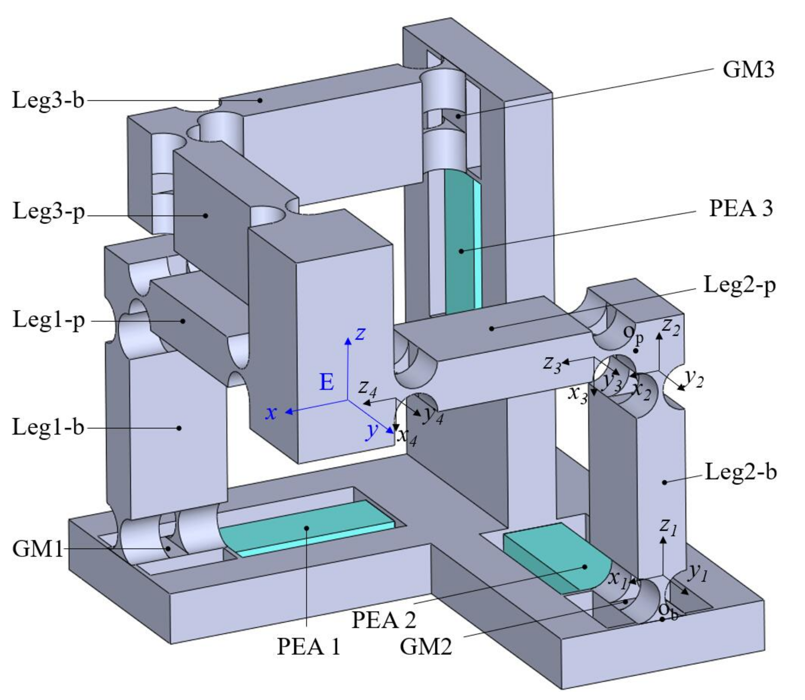
2. Mechanism Design
3. Modeling and Analysis
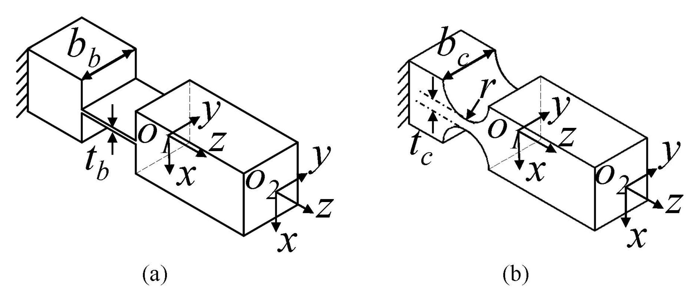
3.1. Modeling Method
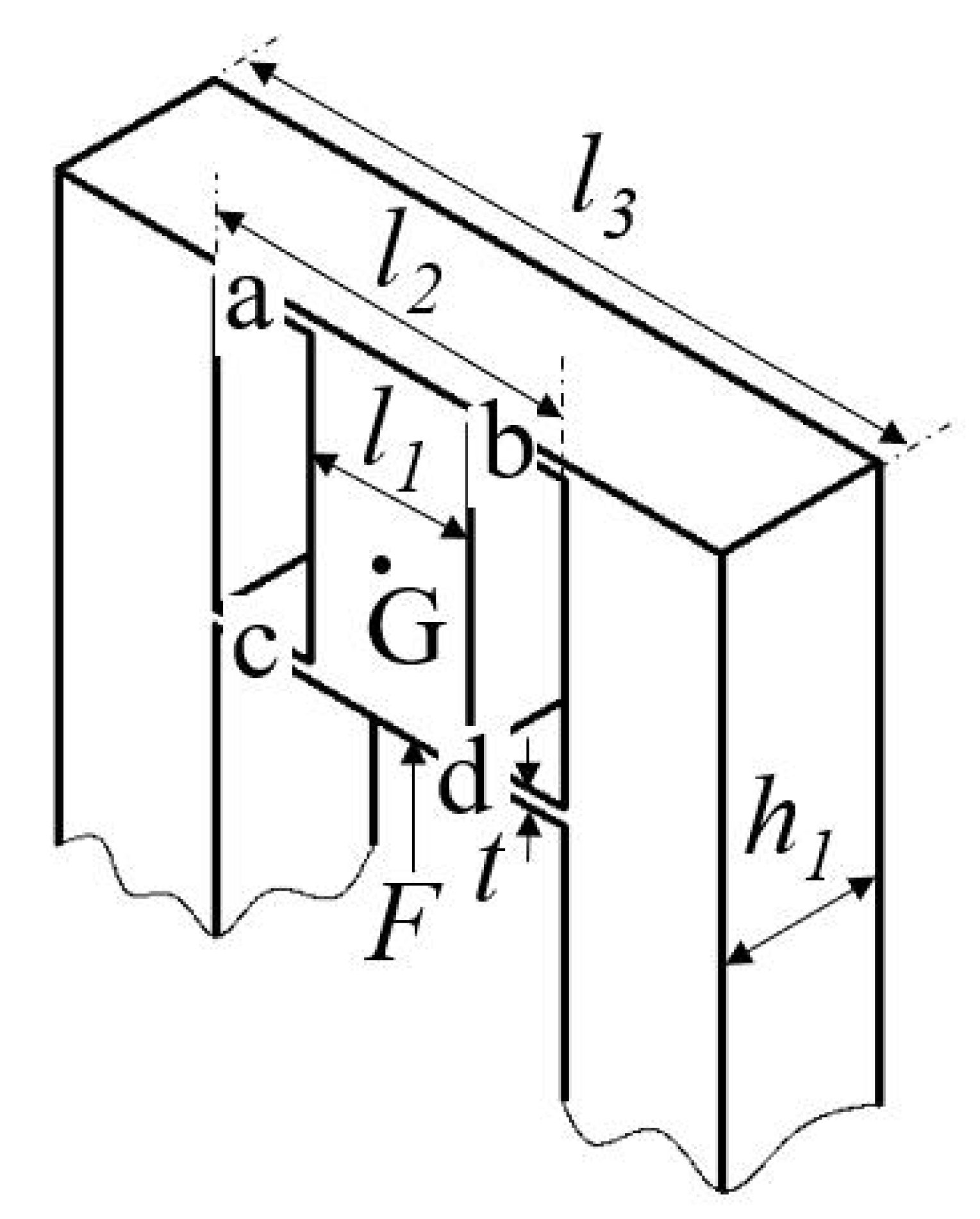
3.2. Input Stiffness of the Proposed Mechanism
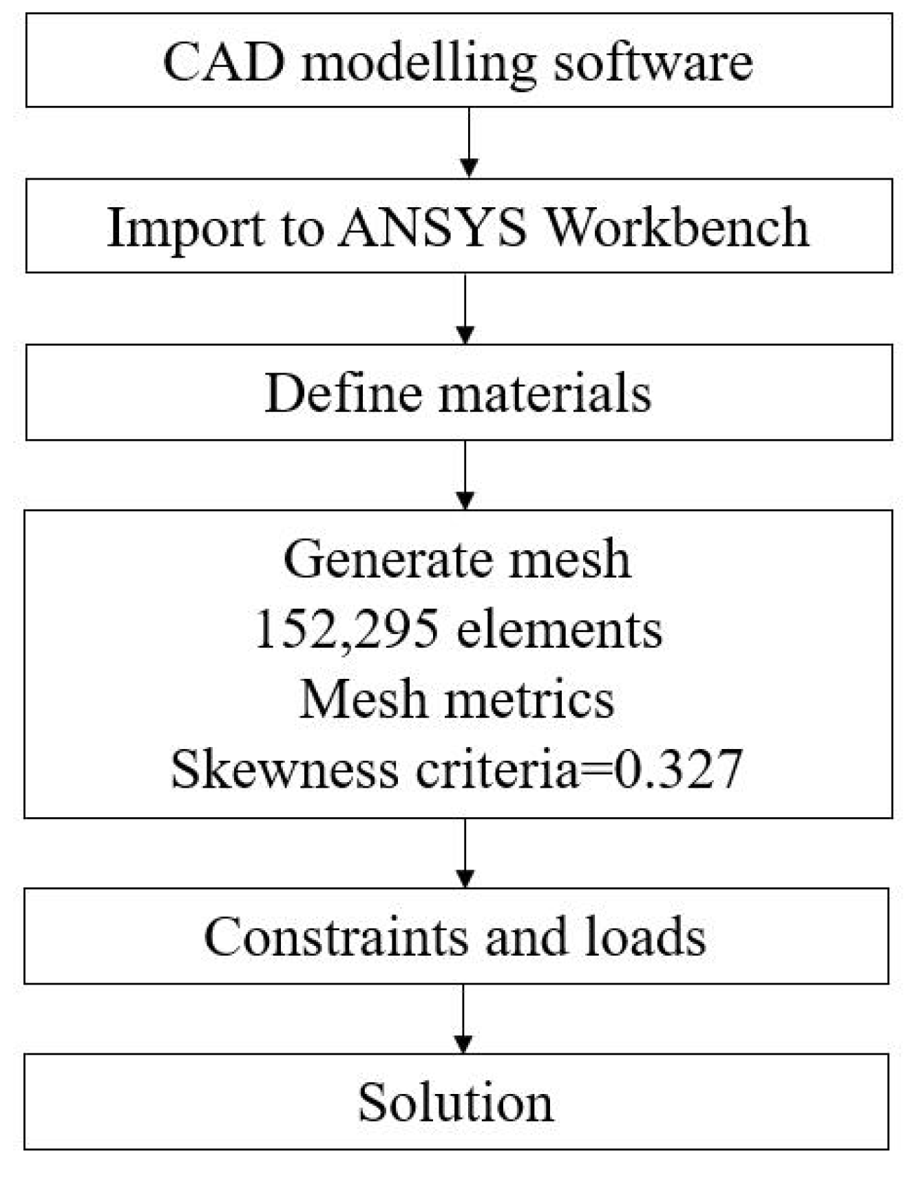
4. Model Validation and Performance Evaluation via FEA
5. Conclusions
Author Contributions
Funding
Institutional Review Board Statement
Informed Consent Statement
Data Availability Statement
Acknowledgments
Conflicts of Interest
References
- Fleming, A.J.; Aphale, S.S.; Moheimani, S.R. A new method for robust damping and tracking control of scanning probe microscope positioning stages. IEEE Trans. Nanotechnol. 2009, 9, 438–448. [Google Scholar] [CrossRef]
- Komati, B.; Clévy, C.; Lutz, P. High bandwidth microgripper with integrated force sensors and position estimation for the grasp of multistiffness microcomponents. IEEE/ASME Trans. Mechatron. 2016, 21, 2039–2049. [Google Scholar] [CrossRef] [Green Version]
- Wang, G.; Xu, Q. Design and precision position/force control of a piezo-driven microinjection system. IEEE/ASME Trans. Mechatron. 2017, 22, 1744–1754. [Google Scholar] [CrossRef]
- Wang, F.; Huo, Z.; Liang, C.; Shi, B.; Tian, Y.; Zhao, X.; Zhang, D. A novel actuator-internal micro/nano positioning stage with an arch-shape bridge-type amplifier. IEEE Trans. Ind. Electron. 2018, 66, 9161–9172. [Google Scholar] [CrossRef] [Green Version]
- Wang, D.; Yang, Q.; Dong, H. A monolithic compliant piezoelectric-driven microgripper: Design, modeling, and testing. IEEE/ASmE Trans. Mechatron. 2011, 18, 138–147. [Google Scholar] [CrossRef]
- Wu, S.; Shao, Z.; Su, H.; Fu, H. An energy-based approach for kinetostatic modeling of general compliant mechanisms. Mech. Mach. Theory 2019, 142, 103588. [Google Scholar] [CrossRef]
- Yang, X.; Zhu, L.; Li, S.; Zhu, W.; Ji, C. Development of a Novel pile-up Structure based nanopositioning mechanism driven by piezoelectric actuator. IEEE/ASME Trans. Mechatron. 2020, 25, 502–512. [Google Scholar] [CrossRef]
- Gao, X.; Liu, Y.; Zhang, S.; Deng, J.; Liu, J. Development of a novel flexure-based XY platform using single bending hybrid piezoelectric actuator. IEEE/ASME Trans. Mechatron. 2022, 1–11. [Google Scholar] [CrossRef]
- Liang, C.; Wang, F.; Huo, Z.; Shi, B.; Tian, Y.; Zhao, X.; Zhang, D. A 2-DOF monolithic compliant rotation platform driven by piezoelectric actuators. IEEE Trans. Ind. Electron. 2019, 67, 6963–6974. [Google Scholar] [CrossRef]
- Gao, X.; Zhang, S.; Deng, J.; Liu, Y. Development of a small two-dimensional robotic spherical joint using a bonded-type piezoelectric actuator. IEEE Trans. Ind. Electron. 2019, 68, 724–733. [Google Scholar] [CrossRef]
- Yang, X.; Zhu, W.L.; Zhu, Z.; Zhu, L.M. Design, assessment, and trajectory control of a novel decoupled robotic nanomanipulator. IEEE/ASME Trans. Mechatron. 2022, 1–12. [Google Scholar] [CrossRef]
- Mitrovic, A.; Nagel, W.S.; Leang, K.K.; Clayton, G.M. Closed-loop range-based control of dual-stage nanopositioning systems. IEEE/ASME Trans. Mechatron. 2020, 26, 1412–1421. [Google Scholar] [CrossRef]
- Hao, G.; Zhu, J. Design of a monolithic double-slider based compliant gripper with large displacement and anti-buckling ability. Micromachines 2019, 10, 665. [Google Scholar] [CrossRef] [Green Version]
- Wadikhaye, S.; Yong, Y.; Moheimani, S.R. Design of a compact serial-kinematic scanner for high-speed atomic force microscopy: An analytical approach. Micro Nano Lett. 2012, 7, 309–313. [Google Scholar] [CrossRef] [Green Version]
- Kenton, B.J.; Leang, K.K. Design and control of a three-axis serial-kinematic high-bandwidth nanopositioner. IEEE/ASME Trans. Mechatron. 2011, 17, 356–369. [Google Scholar] [CrossRef]
- Liu, Y.T.; Li, B.J. A 3-axis precision positioning device using PZT actuators with low interference motions. Precis. Eng. 2016, 46, 118–128. [Google Scholar] [CrossRef]
- Xiao, R.; Shao, S.; Xu, M.; Jing, Z. Design and analysis of a novel piezo-actuated XYθz micropositioning mechanism with large travel and kinematic decoupling. Adv. Mater. Sci. Eng. 2019. [Google Scholar] [CrossRef] [Green Version]
- Muraoka, M.; Sanada, S. Displacement amplifier for piezoelectric actuator based on honeycomb link mechanism. Sens. Actuators A Phys. 2010, 157, 84–90. [Google Scholar] [CrossRef]
- Li, Y.; Xu, Q. A totally decoupled piezo-driven XYZ flexure parallel micropositioning stage for micro/nanomanipulation. IEEE Trans. Autom. Sci. Eng. 2010, 8, 265–279. [Google Scholar] [CrossRef]
- Zhu, Z.; To, S.; Zhu, W.L.; Li, Y.; Huang, P. Optimum design of a piezo-actuated triaxial compliant mechanism for nanocutting. IEEE Trans. Ind. Electron. 2017, 65, 6362–6371. [Google Scholar] [CrossRef]
- Gao, J.; Zeng, Z.; Tang, H.; Chen, X.; Qiu, Q.; He, S.; He, Y.; Yang, Z. Design and assessment of a piezo-actuated 3-DOF flexible nanopositioner with large stroke. In Proceedings of the 2016 IEEE International Conference on Manipulation, Manufacturing and Measurement on the Nanoscale (3M-NANO), Chongqing, China, 18–22 July 2016; pp. 19–24. [Google Scholar]
- Bacher, J.P.; Bottinelli, S.; Breguet, J.M.; Clavel, R. Delta3: Design and control of a flexure hinge mechanism. In Microrobotics and Microassembly III, Proceedings of the Intelligent Systems and Advanced Manufacturing, Boston, MA, USA, 28–31 October 2001; SPIE: Bellingham, WA, USA, 2001; Volume 4568, pp. 135–142. [Google Scholar]
- Tang, X.; Chen, I.M.; Li, Q. Design and nonlinear modeling of a large-displacement XYZ flexure parallel mechanism with decoupled kinematic structure. Rev. Sci. Instruments 2006, 77, 115101. [Google Scholar] [CrossRef]
- Hao, G.; Kong, X. A 3-DOF translational compliant parallel manipulator based on flexure motion. In Proceedings of the ASME International Design Engineering Technical Conferences and Computers and Information in Engineering Conference, San Diego, CA, USA, 30 August–2 September 2009; Volume 49040, pp. 101–110. [Google Scholar]
- Hao, G.; Kong, X. Design and modeling of a large-range modular XYZ compliant parallel manipulator using identical spatial modules. ASME J. Mech. Robot. 2012, 4, 021009. [Google Scholar] [CrossRef]
- Awtar, S.; Ustick, J.; Sen, S. An XYZ parallel-kinematic flexure mechanism with geometrically decoupled degrees of freedom. ASME J. Mech. Robot. 2013, 5, 015001. [Google Scholar] [CrossRef]
- Awtar, S.; Quint, J.; Ustick, J. Experimental characterization of a large-range parallel kinematic XYZ flexure mechanism. ASME J. Mech. Robot. 2021, 13, 015001. [Google Scholar] [CrossRef]
- Gallego, J.A.; Herder, J. Synthesis methods in compliant mechanisms: An overview. In Proceedings of the ASME International Design Engineering Technical Conferences and Computers and Information in Engineering Conference, San Diego, CA, USA, 30 August–2 September 2009; Volume 49040, pp. 193–214. [Google Scholar]
- Sigmund, O. On the design of compliant mechanisms using topology optimization. J. Struct. Mech. 1997, 25, 493–524. [Google Scholar] [CrossRef]
- Kumar, P.; Schmidleithner, C.; Larsen, N.; Sigmund, O. Topology optimization and 3D printing of large deformation compliant mechanisms for straining biological tissues. Struct. Multidiscip. Optim. 2021, 63, 1351–1366. [Google Scholar] [CrossRef]
- Kong, X.; Gosselin, C.M. Kinematics and singularity analysis of a novel type of 3-CRR 3-DOF translational parallel manipulator. Int. J. Robot. Res. 2002, 21, 791–798. [Google Scholar] [CrossRef]
- Gosselin, C.; Kong, X.; Foucault, S.; Bonev, I. A fully decoupled 3-dof translational parallel mechanism. In Proceedings of the 4th Chemnitz Parallel Kinematics Seminar, Chemnitz, Germany, 20–21 April 2004; pp. 595–610. [Google Scholar]
- Quennouelle, C.; Gosselin, C. Kinematostatic modeling of compliant parallel mechanisms. Meccanica 2011, 46, 155–169. [Google Scholar] [CrossRef]
- Ling, M.; Howell, L.L.; Cao, J.; Chen, G. Kinetostatic and dynamic modeling of flexure-based compliant mechanisms: A survey. Appl. Mech. Rev. 2020, 72, 030802. [Google Scholar] [CrossRef] [Green Version]
- Bilancia, P.; Berselli, G. An overview of procedures and tools for designing nonstandard beam-based compliant mechanisms. Comput.-Aided Des. 2021, 134, 103001. [Google Scholar] [CrossRef]
- Ling, M.; Song, D.; Zhang, X.; He, X.; Li, H.; Wu, M.; Cao, L.; Lu, S. Analysis and design of spatial compliant mechanisms using a 3-D dynamic stiffness model. Mech. Mach. Theory 2022, 168, 104581. [Google Scholar] [CrossRef]
- Howell, L.L.; Magleby, S.P.; Olsen, B.M. Handbook of Compliant Mechanisms; John Wiley & Sons Incorporated: Hoboken, NJ, USA, 2013; p. 311. [Google Scholar]
- Xie, Y.; Li, Y.; Cheung, C.F.; Zhu, Z.; Chen, X. Design and analysis of a novel compact XYZ parallel precision positioning stage. Microsyst. Technol. 2021, 27, 1925–1932. [Google Scholar] [CrossRef]
- Chen, X.; Li, Y. Design and analysis of a new high precision decoupled XY compact parallel micromanipulator. Micromachines 2017, 8, 82. [Google Scholar] [CrossRef]
- Koseki, Y.; Tanikawa, T.; Koyachi, N.; Arai, T. Kinematic analysis of a translational 3-dof micro-parallel mechanism using the matrix method. Adv. Robot. 2002, 16, 251–264. [Google Scholar] [CrossRef]
- Moritoki, Y.; Furukawa, T.; Sun, J.; Yokoyama, M.; Shimono, T.; Yamada, T.; Nishiwaki, S.; Kageyama, T.; Fukuda, J.; Mukai, M.; et al. 3D-printed micro-tweezers with a compliant mechanism designed using topology optimization. Micromachines 2021, 12, 579. [Google Scholar] [CrossRef] [PubMed]
- Li, X.; Yu, D.; Cao, T.; Wen, Z.; Lu, C.; Liu, W.; Zhu, C.; Wu, D. 3D printing and dynamic modeling of a polymer-based bimodal piezoelectric motor. Smart Mater. Struct. 2020, 30, 025003. [Google Scholar] [CrossRef]
- Clark, L.; Shirinzadeh, B.; Bhagat, U.; Smith, J.; Zhong, Y. Development and control of a two DOF linear–angular precision positioning stage. Mechatronics 2015, 32, 34–43. [Google Scholar] [CrossRef]


| GM 3 | Legs and the Motion Platform | ||
|---|---|---|---|
| Symbol | Value (mm) | Symbol | Value (mm) |
| 10 | 41 | ||
| 22 | 4 | ||
| 42 | 20 | ||
| 10 | 10 | ||
| t | 0.6 | 1 | |
| r | 4.5 | ||
| 20 | |||
| 40 | |||
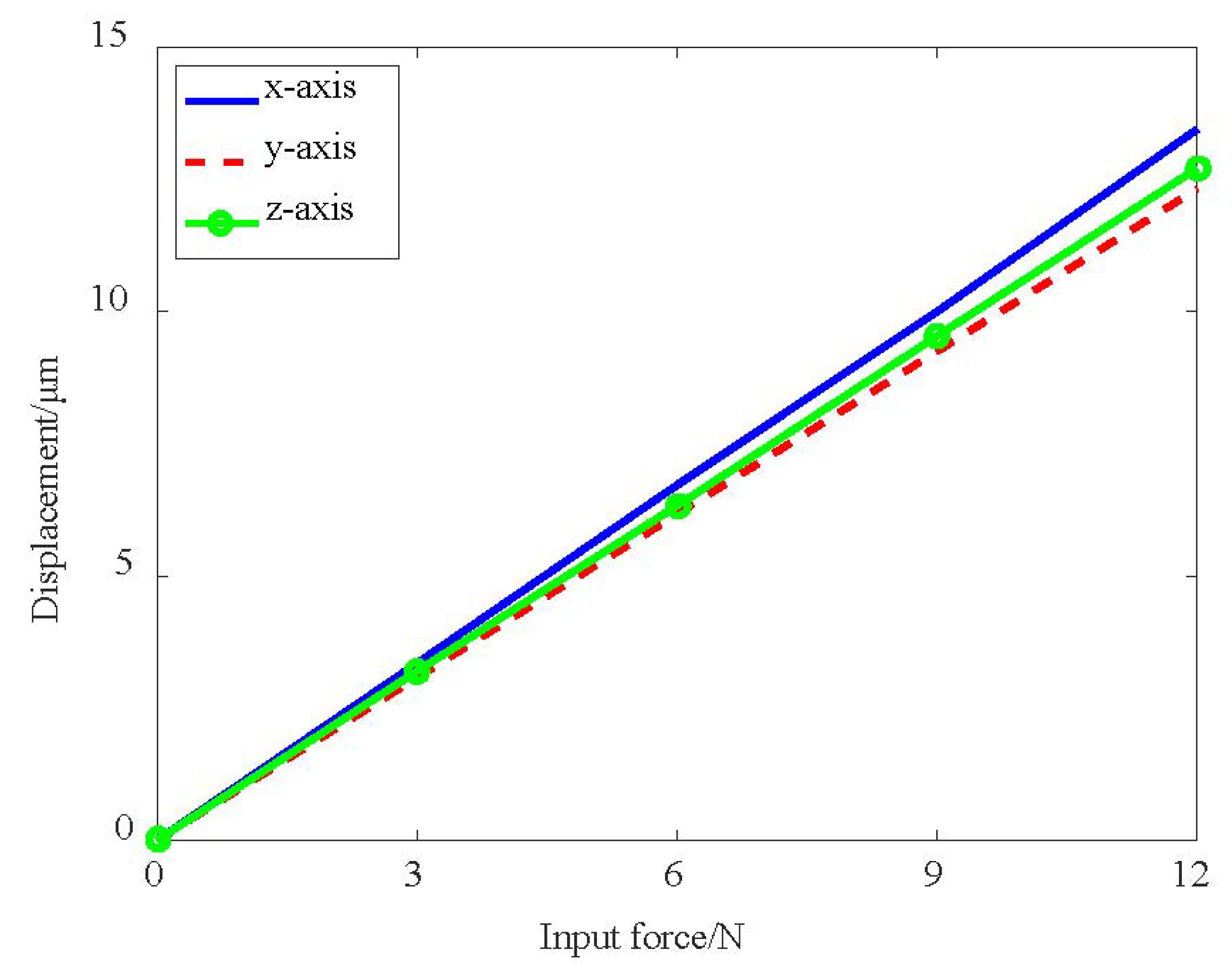
| Methods | x-Axis Input/Output Stiffness (N/µm) | y-Axis Input/Output Stiffness (N/µm) | z-Axis Input/Output Stiffness (N/µm) |
|---|---|---|---|
| Analytical model | 0.82 | 0.82 | 0.82 |
| FEA | 0.89/0.69 | 0.97/0.70 | 0.94/0.72 |
| Error | −18%/19% | −15%/17% | −13%/14% |
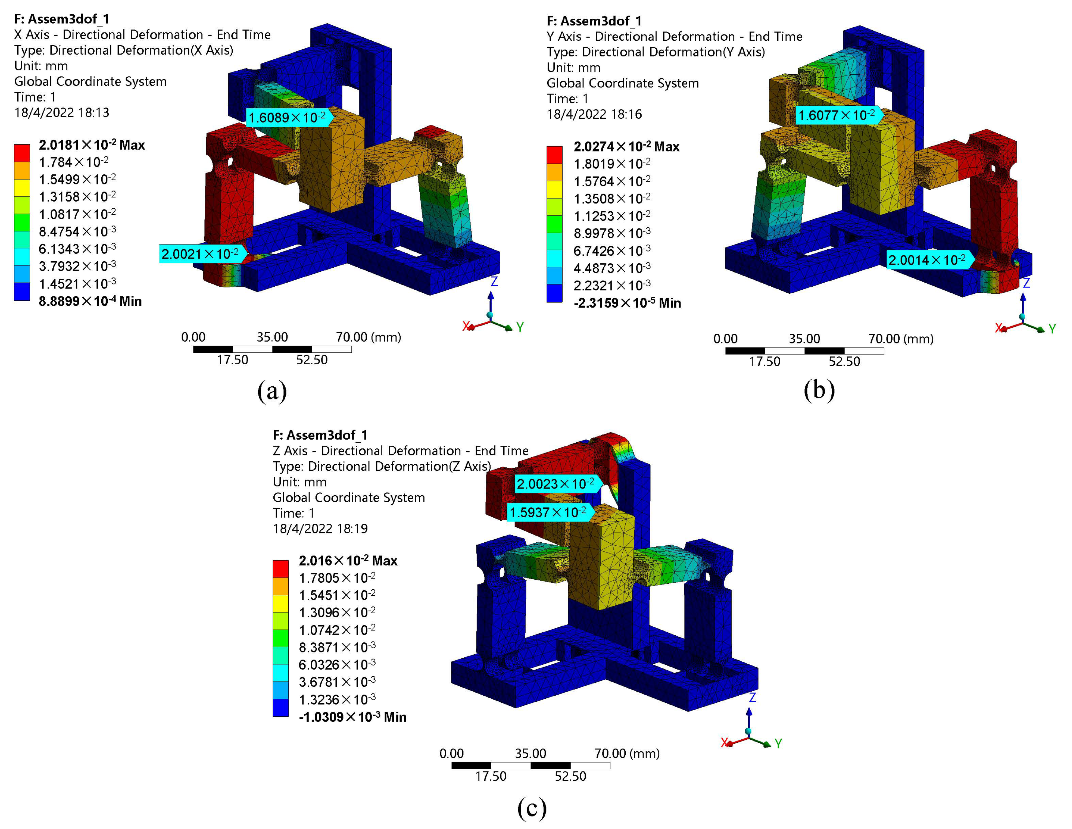
| Input Displacement (µm) | Output Displacement (µm) | ||||
|---|---|---|---|---|---|
| x | y | z | x | y | z |
| 20 | - | - | 16 | 1.40 | −0.84 |
| - | 20 | - | 2.82 | 16 | −0.62 |
| - | - | 20 | −0.96 | 1.41 | 16 |
Publisher’s Note: MDPI stays neutral with regard to jurisdictional claims in published maps and institutional affiliations. |
© 2022 by the authors. Licensee MDPI, Basel, Switzerland. This article is an open access article distributed under the terms and conditions of the Creative Commons Attribution (CC BY) license (https://creativecommons.org/licenses/by/4.0/).
Share and Cite
Xie, Y.; Li, Y.; Cheung, C. Design and Modeling of a Novel Tripteron-Inspired Triaxial Parallel Compliant Manipulator with Compact Structure. Micromachines 2022, 13, 678. https://doi.org/10.3390/mi13050678
Xie Y, Li Y, Cheung C. Design and Modeling of a Novel Tripteron-Inspired Triaxial Parallel Compliant Manipulator with Compact Structure. Micromachines. 2022; 13(5):678. https://doi.org/10.3390/mi13050678
Chicago/Turabian StyleXie, Yanlin, Yangmin Li, and Chifai Cheung. 2022. "Design and Modeling of a Novel Tripteron-Inspired Triaxial Parallel Compliant Manipulator with Compact Structure" Micromachines 13, no. 5: 678. https://doi.org/10.3390/mi13050678