
Integration Technology with Thin Films Co-Fabricated in Laminated Composite Structures for Defect Detection and Damage Monitoring


Abstract
1. Introduction
2. Related Work
3. Materials and Methods
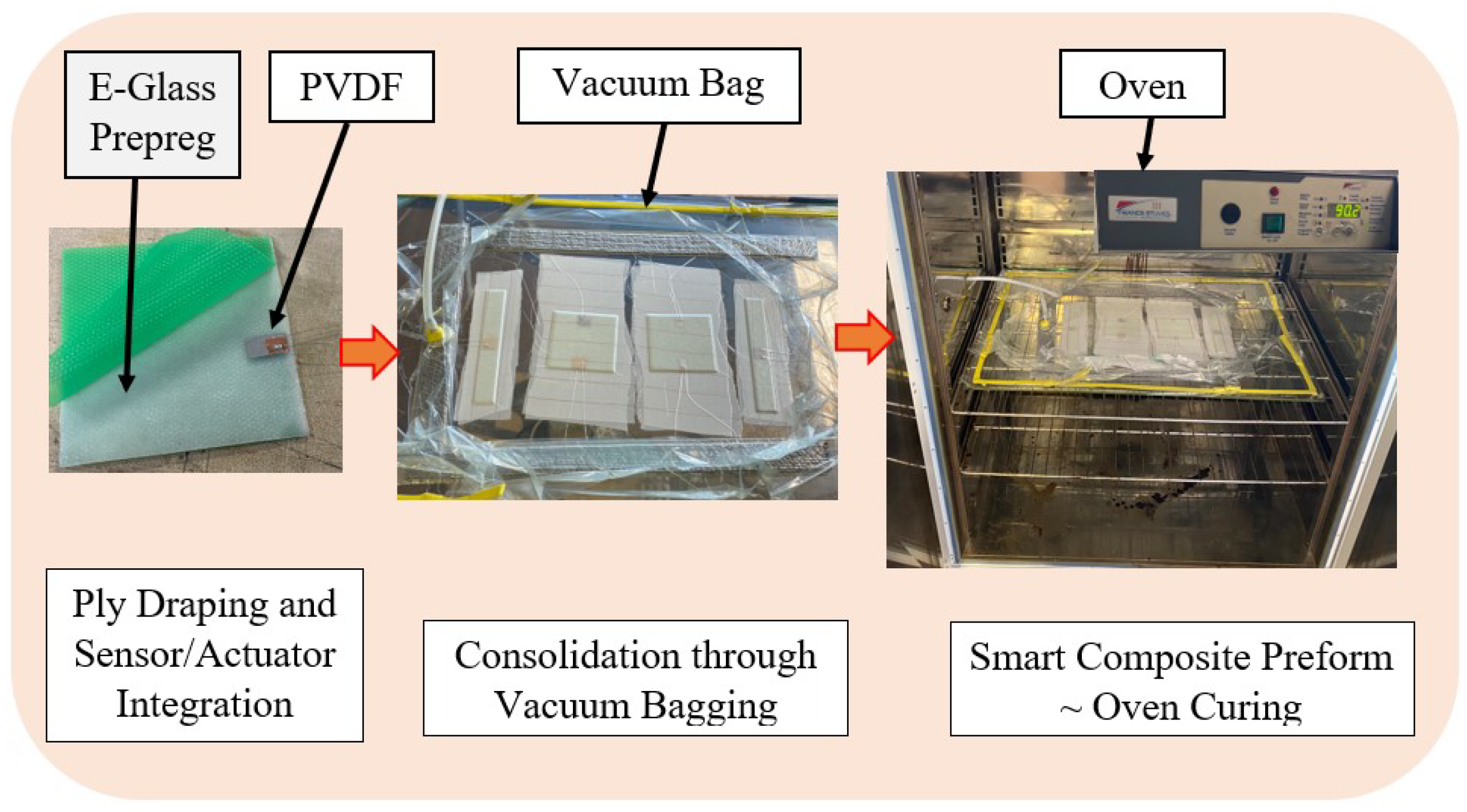
3.1. Materials Used and the Fabrication Processes Applied
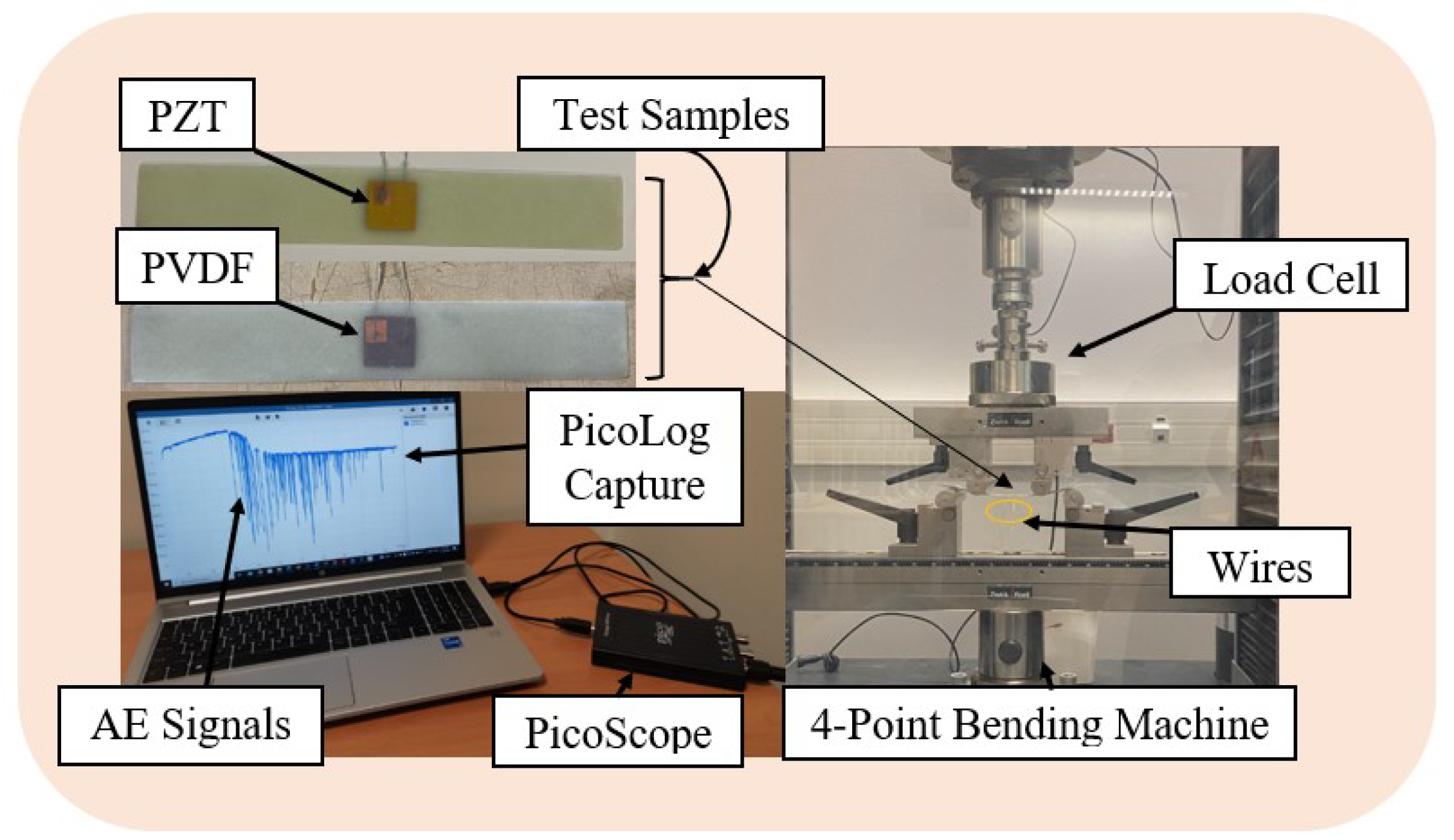
3.2. Evaluation of the Viability of Embedded Piezo-Type Sensors for Structural Health Monitoring Using a Passive Sensing Approach and Their Impact on the Structure
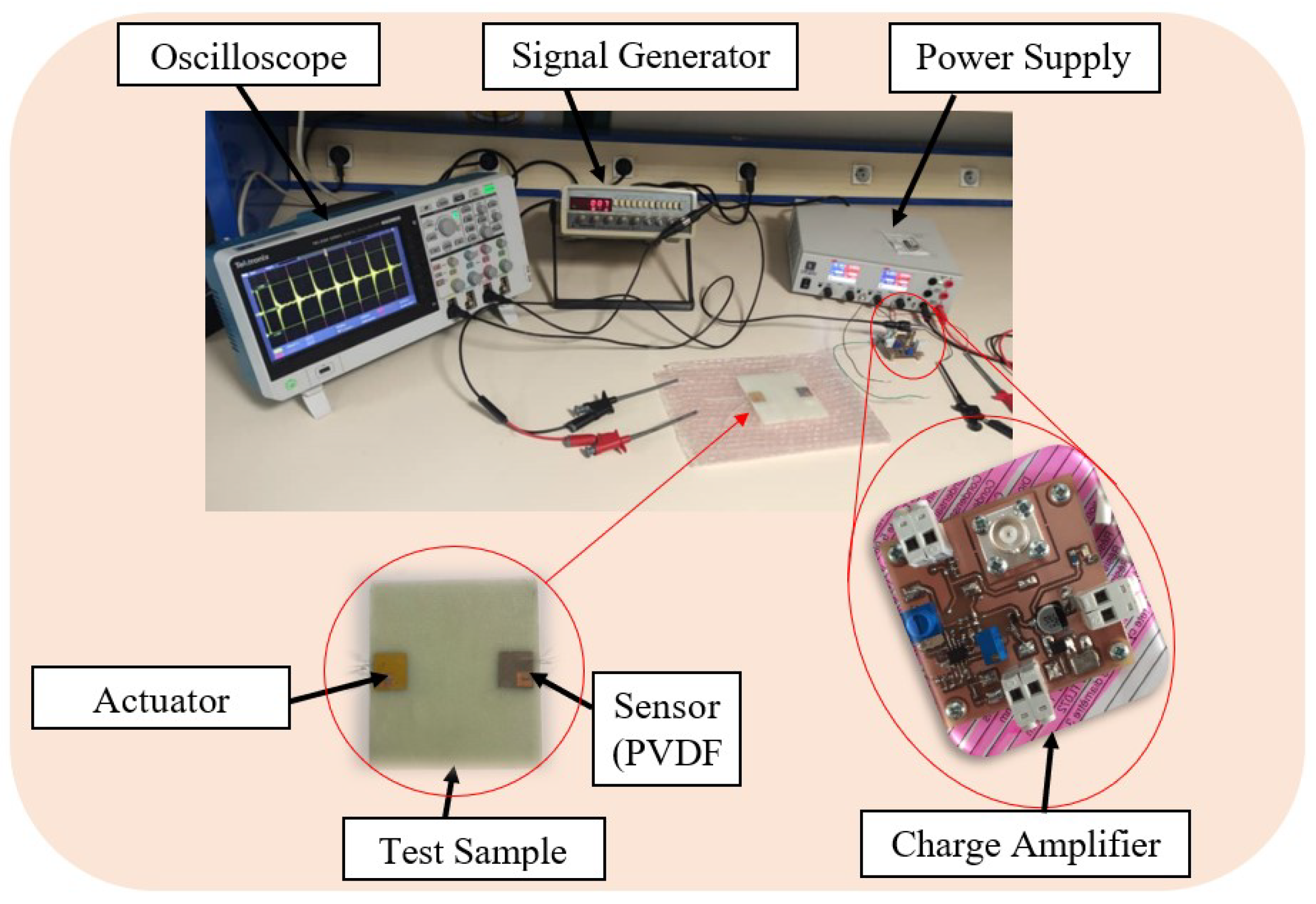
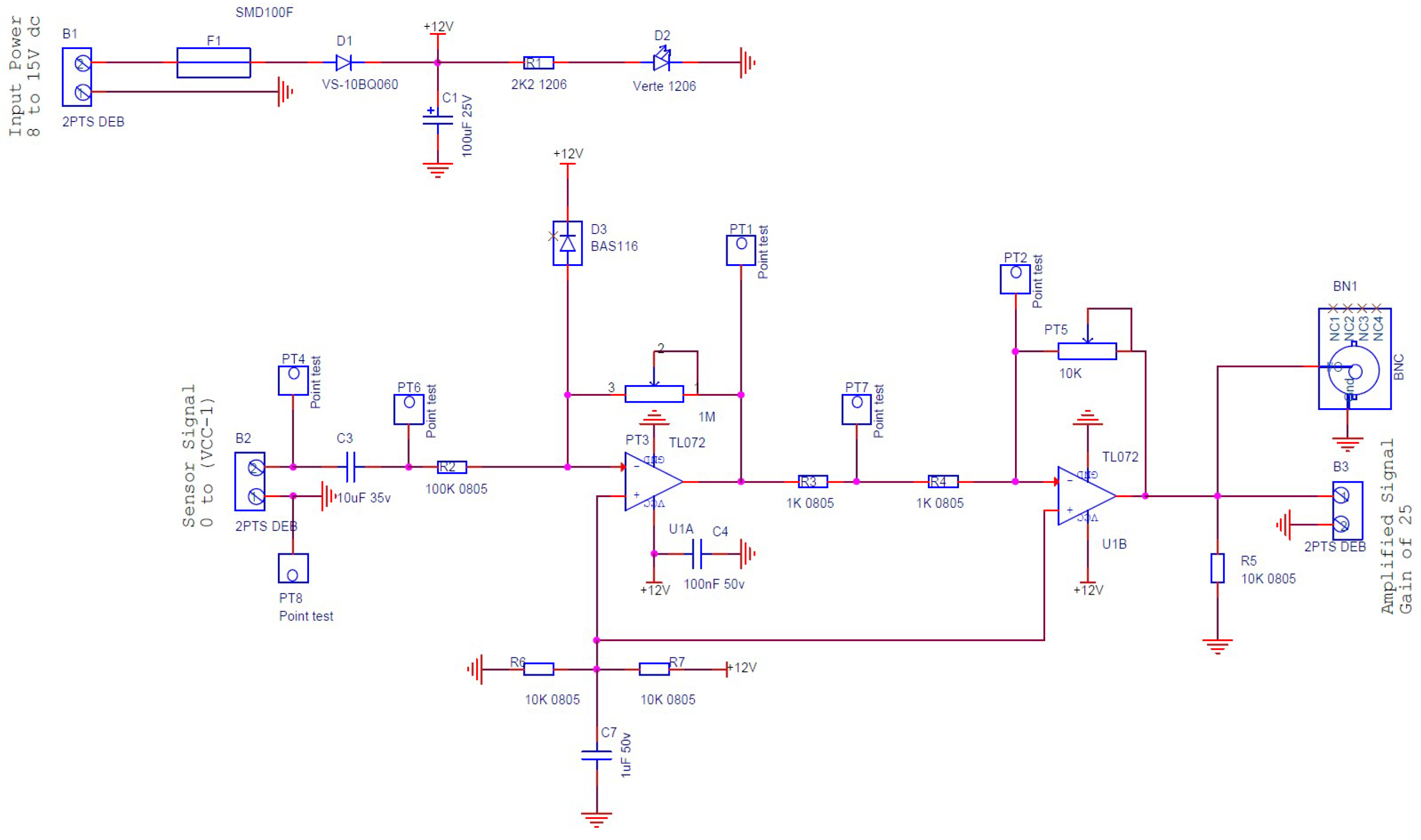
3.3. Evaluation of Actuator–Sensor Configuration in Active Sensing Approach
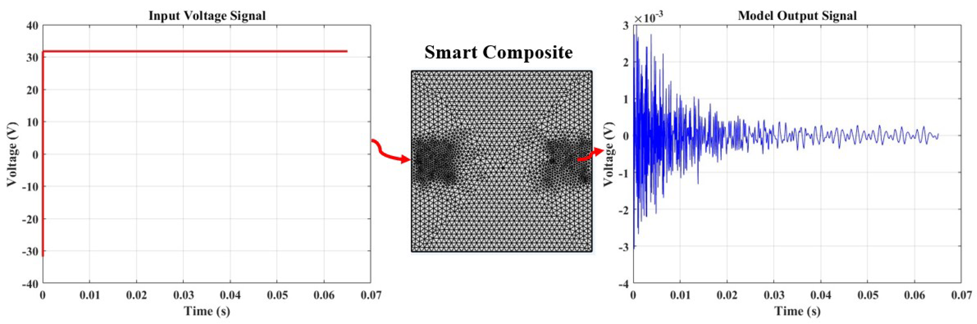
3.4. Assessment of Finite Element Modeling (FEM) through Active Sensing
4. Results and Discussion
4.1. Passive Sensing Approach
4.1.1. Mechanical Aspect
4.1.2. Sensor Performance
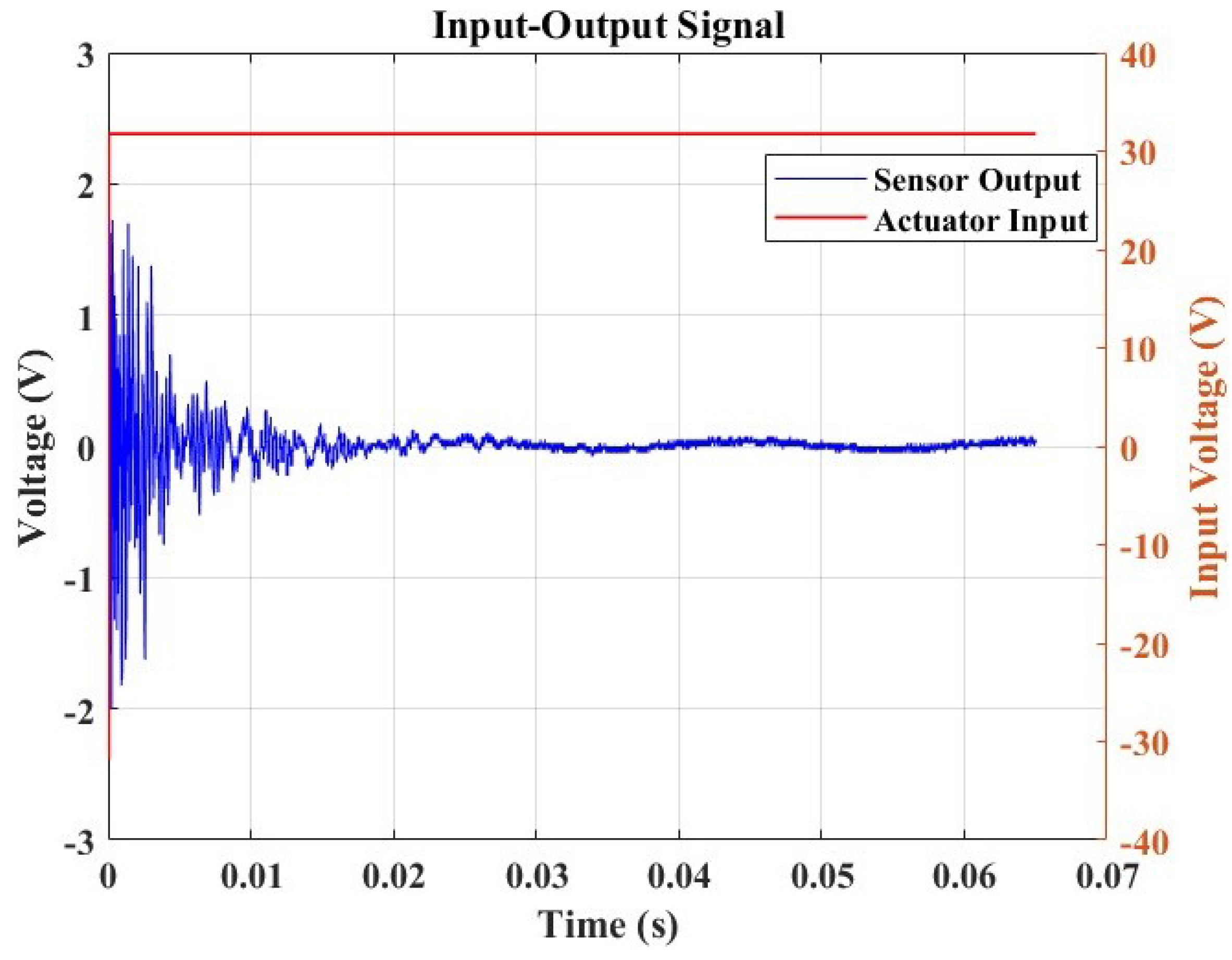
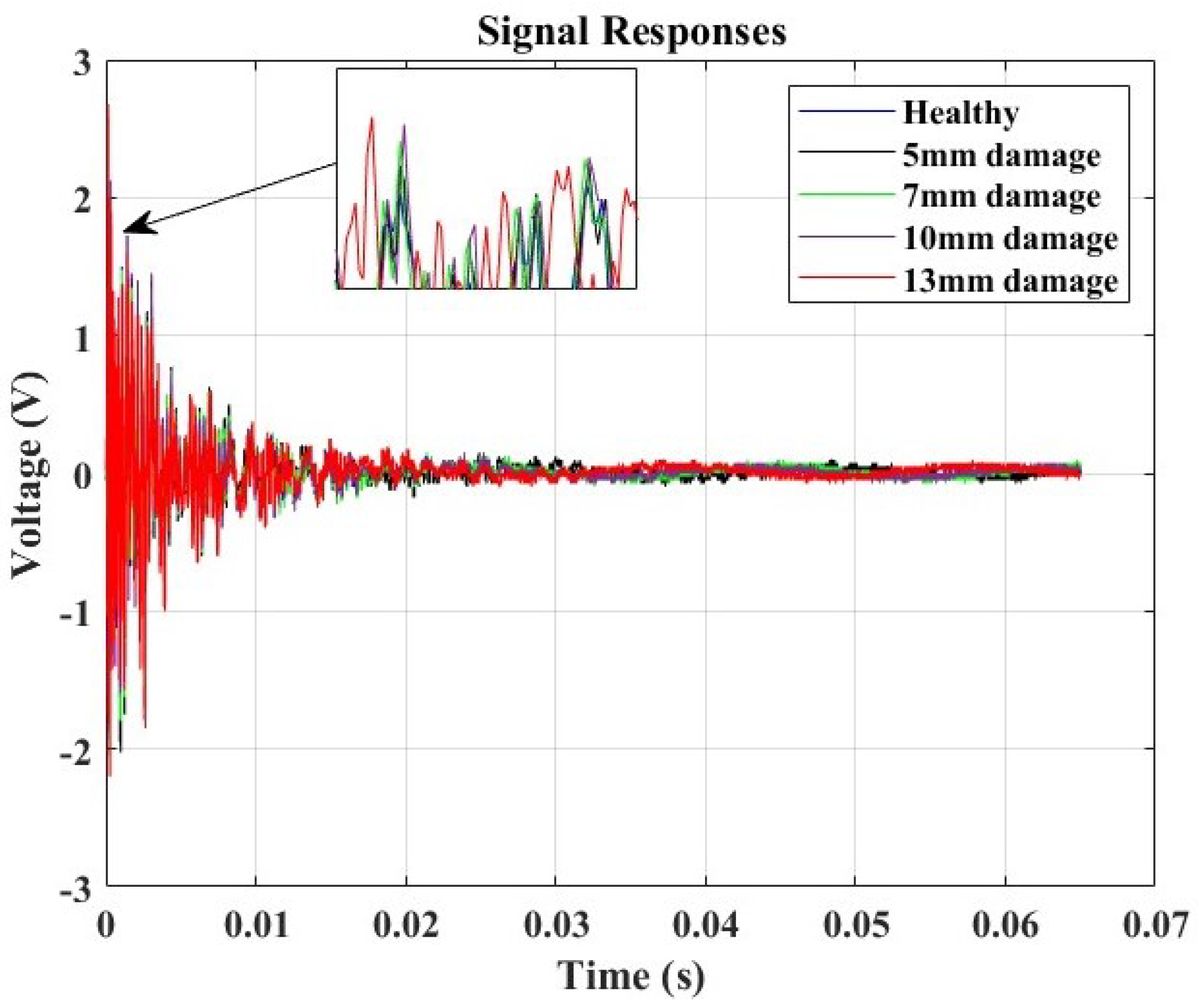
4.2. Active Sensing Approach
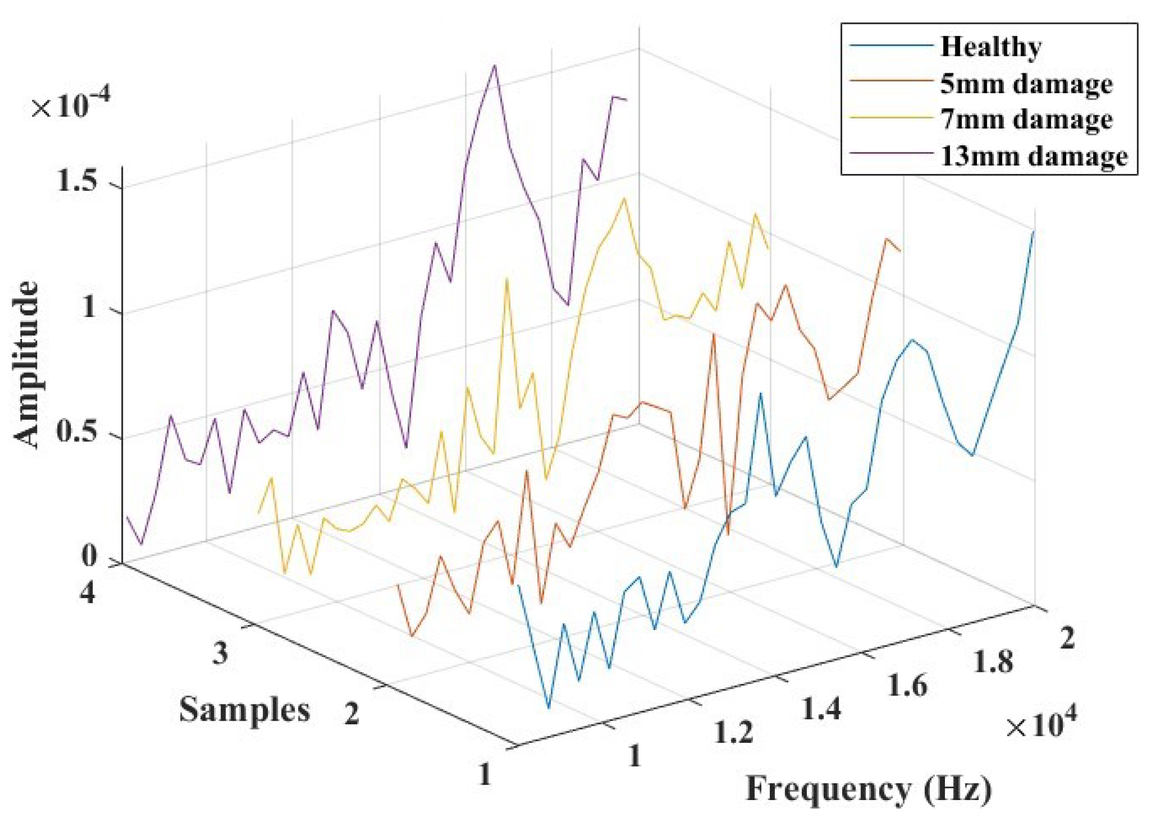
Numerical Analysis
5. Conclusions
Author Contributions
Funding
Data Availability Statement
Conflicts of Interest
References
- Maksuti, R. Applications of smart materials in mechatronics technology. JAS-SUT J. Appl. Sci.-SUT 2019, 5, 9–13. [Google Scholar]
- Langat, K.R.; De Luycker, E.; Noureddine, F.; Rakotondrabe, M. Robotic-Assisted Measurement of Fabrics for the Characterization of the Shear Tension Coupling. Key Eng. Mater. 2022, 926, 1303–1316. [Google Scholar] [CrossRef]
- Chen, Y.; Zhang, J.; Li, Z.; Zhang, H.; Chen, J.; Yang, W.; Yu, T.; Liu, W.; Li, Y. Manufacturing Technology of Lightweight Fiber-Reinforced Composite Structures in Aerospace: Current Situation and toward Intellectualization. Aerospace 2023, 10, 206. [Google Scholar] [CrossRef]
- Grootel, A.; Chang, J.; Wardle, B.; Olivetti, E. Manufacturing variability drives significant environmental and economic impact: The case of carbon fiber reinforced polymer composites in the aerospace industry. J. Clean. Prod. 2020, 261, 121087. [Google Scholar] [CrossRef]
- Dragan, K.; Dziendzikowski, M.; Kurnyta, A.; Leski, A.; Bienias, J. Structural health monitoring of composite structures with use of embedded PZT piezoelectric sensors. In Proceedings of the ECCM-16th European Conference on Composite Materials, Seville, Spain, 22–26 June 2014; pp. 22–26. [Google Scholar]
- Jagadale, U.; Nayak, C.; Narute, G. Structural health monitoring using piezo-ceramics smart material. In Proceedings of the 9th International Conference on Sustainable Built Environment, Kandy, Sri Lanka, 13–15 December 2018. [Google Scholar]
- Chen, X.; Meyer, Y.; Lachat, R.; Ouisse, M. Structural health monitoring of a smart composite structure with a Time-of-Flight method. In Proceedings of the MEDYNA 2017: 2nd Euro-Mediterranean Conference on Structural Dynamics and Vibroacoustics, Sevilla, Spain, 25–27 April 2017; pp. 25–28. [Google Scholar]
- Langat, R.K.; De Luycker, E.; Cantarel, A.; Rakotondrabe, M. Toward the development of a new smart composite structure based on piezoelectric polymer and flax fiber materials: Manufacturing and experimental characterization. Mech. Adv. Mater. Struct. 2023, 1–15. [Google Scholar] [CrossRef]
- Bafumba Liseli, J.; Agnus, J.; Lutz, P.; Rakotondrabe, M. An overview of Piezoelectric Self-Sensing Actuation for Nanopositioning Applications: Electrical circuits, Displacement and Force estimation. IEEE Trans. Instrum. Meas. 2020, 69, 2–14. [Google Scholar] [CrossRef]
- Ivan, I.A.; Aljanaideh, O.; Agnus, J.; Lutz, P.; Rakotondrabe, M. Quasi-static displacement self-sensing measurement for a 2-DOF piezoelectric cantilevered actuator. IEEE Trans. Ind. Electron. 2017, 64, 6330–6337. [Google Scholar] [CrossRef]
- Su, Y.F.; Han, G.; Kong, Z.; Nantung, T.; Lu, N. Embeddable Piezoelectric Sensors for Strength Gain Monitoring of Cementitious Materials: The Influence of Coating Materials. Eng. Sci. 2020, 11, 66–75. [Google Scholar] [CrossRef]
- Ji, Y.; Chen, A.; Chen, Y.; Han, X.; Li, B.; Gao, Y.; Liu, C.; Xie, J. A state-of-the-art review of concrete strength detection/monitoring methods: With special emphasis on PZT transducers. Constr. Build. Mater. 2023, 362, 129742. [Google Scholar] [CrossRef]
- Su, Y.F.; Han, G.; Amran, A.; Nantung, T.; Lu, N. Instantaneous monitoring the early age properties of cementitious materials using PZT-based electromechanical impedance (EMI) technique. Constr. Build. Mater. 2019, 225, 340–347. [Google Scholar] [CrossRef]
- Meshkinzar, A.; Al-Jumaily, A.M. Cylindrical Piezoelectric PZT Transducers for Sensing and Actuation. Sensors 2023, 23, 3042. [Google Scholar] [CrossRef]
- Su, Y.F.; Kotian, R.R.; Lu, N. Energy harvesting potential of bendable concrete using polymer based piezoelectric generator. Compos. Part Eng. 2018, 153, 124–129. [Google Scholar] [CrossRef]
- Rougeot, P.; Mohand-Ousaid, A.; Gendreau, D.; Rakotondrabe, M. Design, modeling and simulation of a three-layers piezoelectric cantilevered actuator with collocated sensor. SPIE Sens. Technol. 2016, 9859, 139–150. [Google Scholar] [CrossRef]
- Paradies, R.; Ruge, M. In situ fabrication of active fibre reinforced structures with integrated piezoelectric actuators. Smart Mater. Struct. 2000, 9, 220. [Google Scholar] [CrossRef]
- Henrandez, J.C.; Escareno, J.A.; Doger, G.; Rakotondrabe, M. Getting Started with PEAs-Based Flapping-Wing Mechanisms for Micro Aerial Systems. Actuators 2016, 5, 14. [Google Scholar] [CrossRef]
- Chen, X. Development of a Low-Cost In-Situ Material Characterization Method and Experimental Studies of Smart Composite Structures. Ph.D. Thesis, Université Bourgogne Franche-Comté, Besançon, France, 2019. [Google Scholar]
- Konka, H.P. Embedded Piezoelectric Fiber Composite Sensors for Applications in Composite Structures. Ph.D. Thesis, Agricultural & Mechanical College, Louisiana State University, Baton Rouge, LA, USA, 2011. [Google Scholar]
- Schulze, R.; Streit, P.; Fischer, T.; Tsapkolenko, A.; Heinrich, M.; Sborikas, M.; Kroll, L.; Gessner, T.; Wegener, M. Fiber-reinforced composite structures with embedded piezoelectric sensors. In Proceedings of the SENSORS, 2014 IEEE, Valencia, Spain, 2–5 November 2014; pp. 1563–1566. [Google Scholar] [CrossRef]
- Pearson, M.; Eaton, M.; Pullin, R.; Featherston, C.; Holford, K. Energy Harvesting for Aerospace Structural Health Monitoring Systems. J. Phys. Conf. Ser. 2012, 382, 012025. [Google Scholar] [CrossRef]
- Ju, M.; Dou, Z.; Li, J.W.; Qiu, X.; Shen, B.; Zhang, D.; Yao, F.Z.; Gong, W.; Wang, K. Piezoelectric Materials and Sensors for Structural Health Monitoring: Fundamental Aspects, Current Status, and Future Perspectives. Sensors 2023, 23, 543. [Google Scholar] [CrossRef]
- Masmoudi, S.; El Mahi, A.; Turki, S.; El Guerjouma, R. Structural Health Monitoring by Acoustic Emission of Smart Composite Laminates Embedded with Piezoelectric Sensor. In Proceedings of the Design and Modeling of Mechanical Systems, Djerba, Tunisia, 25–27 March 2013; Springer: Berlin/Heidelberg, Germany, 2013; pp. 307–314. [Google Scholar] [CrossRef]
- Güemes, A.; Fernández-López, A.; Díaz-Maroto, P.F.; Lozano, A.; Sierra-Perez, J. Structural Health Monitoring in Composite Structures by Fiber-Optic Sensors. Sensors 2018, 18, 1094. [Google Scholar] [CrossRef]
- Philibert, M.; Yao, K.; Gresil, M.; Soutis, C. Lamb waves-based technologies for structural health monitoring of composite structures for aircraft applications. Eur. J. Mater. 2022, 2, 436–474. [Google Scholar] [CrossRef]
- Güemes, A. SHM technologies and applications in aircraft structures. In Proceedings of the 5th International Symposium on NDT in Aerospace, Singapore, 13–15 November 2013; Volume 1315. [Google Scholar]
- Lampani, L.; Gaudenzi, P. Innovative composite material component with embedded self-powered wireless sensor device for structural monitoring. Compos. Struct. 2018, 202, 136–141. [Google Scholar] [CrossRef]
- Hornig, A.; Frohberg, R.; Bätzel, T.; Gude, M.; Modler, N. Embedded sensing and actuating in CFRP composite structures—Concept and technology demonstration for tailored embeddable sensor-actuator layers (TEmSAL). Smart Mater. Struct. 2022, 31, 095007. [Google Scholar] [CrossRef]
- Lampani, L.; Sarasini, F.; Tirillò, J.; Gaudenzi, P. Analysis of damage in composite laminates with embedded piezoelectric patches subjected to bending action. Compos. Struct. 2018, 202, 935–942. [Google Scholar] [CrossRef]
- Janeliukstis, R.; Mironovs, D. Smart Composite Structures with Embedded Sensors for Load and Damage Monitoring—A Review. Mech. Compos. Mater. 2021, 57, 131–152. [Google Scholar] [CrossRef]
- Qing, X.; Li, W.; Wang, Y.; Sun, H. Piezoelectric Transducer-Based Structural Health Monitoring for Aircraft Applications. Sensors 2019, 19, 545. [Google Scholar] [CrossRef]
- Feng, T.; Bekas, D.; Aliabadi, M.H.F. Active Health Monitoring of Thick Composite Structures by Embedded and Surface-Mounted Piezo Diagnostic Layer. Sensors 2020, 20, 3410. [Google Scholar] [CrossRef]
- Abdelrahman, K.; Al Saaideh, M.; AlJanaideh, M.; Rakotondrabe, M. Output Estimation and Failure Detection in Piezoelectric Actuators using Transmissibility Operators. Lett. Dyn. Syst. Control 2023, 3, 011007. [Google Scholar]
- Jiao, P.; Egbe, K.-J.I.; Xie, Y.; Matin Nazar, A.; Alavi, A.H. Piezoelectric Sensing Techniques in Structural Health Monitoring: A State-of-the-Art Review. Sensors 2020, 20, 3730. [Google Scholar] [CrossRef]
- Paget, C.; Levin, K.; Delebarre, C. Actuation performance of embedded piezoceramic transducer in mechanically loaded composites. Smart Mater. Struct. 2002, 11, 886. [Google Scholar] [CrossRef]
- Giurgiutiu, V. 17—Structural health monitoring (SHM) of aerospace composites. In Polymer Composites in the Aerospace Industry, 2nd ed.; Irving, P., Soutis, C., Eds.; Woodhead Publishing Series in Composites Science and Engineering; Woodhead Publishing: Sawston, UK, 2020; pp. 491–558. [Google Scholar] [CrossRef]
- Ihn, J.B.; Chang, F.K. Pitch-catch Active Sensing Methods in Structural Health Monitoring for Aircraft Structures. Struct. Health Monit. 2008, 7, 5–19. [Google Scholar] [CrossRef]
- Ivan, I.; Rakotondrabe, M.; Bourquin, R.; Chaillet, N.; Lutz, P.; Poncot, J.C.; Duffait, R.; Bauer, O. Comparative material study between PZT ceramic and newer crystalline PMN-PT and PZN-PT materials for composite bimorph actuators. Rev. Adv. Mater. Sci. 2010, 24, 1–9. [Google Scholar]
- ASTM D6272; Standard Test Methods for Flexural Properties of Unreinforced and Reinforced Plastics and Electrical Insulating Materials. In Annual Book of ASTM Standards; ASTM Internationa: West Conshohocken, PA, USA, 2020. Available online: www.astm.org (accessed on 8 February 2024).
- Tuloup, C.; Harizi, W.; Aboura, Z.; Meyer, Y. Structural health monitoring of polymer-matrix composite using embedded piezoelectric ceramic transducers during several four-points bending tests. Smart Mater. Struct. 2020, 29, 125011. [Google Scholar] [CrossRef]
- Ghafari, E.; Lu, N. Self-polarized electrospun polyvinylidene fluoride (PVDF) nanofiber for sensing applications. Compos. Part B Eng. 2019, 160, 1–9. [Google Scholar] [CrossRef]
- Griffin, C.; Giurgiutiu, V. Piezoelectric Wafer Active Sensor Transducers for Acoustic Emission Applications. Sensors 2023, 23, 7103. [Google Scholar] [CrossRef] [PubMed]
- Nechibvute, A.; Chawanda, A.; Luhanga, P. Finite element modeling of a piezoelectric composite beam and comparative performance study of piezoelectric materials for voltage generation. Int. Sch. Res. Not. 2012, 2012, 921361. [Google Scholar] [CrossRef]
- Yahiaoui, M.; Marconnet, M.; Jlaiel, K.; Paris, J.Y.; Denape, J. Acoustic emission characterization of transgranular cracks in WC–Co cemented carbides During a one-way scratch. Tribol. Lett. 2021, 69, 133. [Google Scholar] [CrossRef]


| Material | Density | Area Weight | Fiber Volume Fraction | Young’s Modulus | Curing Temperature |
|---|---|---|---|---|---|
| E-Glass Woven prepreg | 1800 [kg/m3] | 300 [g/m2] | 55 [%] | 21 [GPa] | 90 [°C] for 90 min |
| Material | Density | Max Operating Temperature | Piezo Strain Constant | Young’s Modulus | Thickness |
|---|---|---|---|---|---|
| PVDF Film | 1780 [kg/m3] | 100 [°C] | d31 = 23 | 2–4 [GPa] | 0.052 [mm] |
| d33 = −33 | |||||
| [(10−12) C/N] | |||||
| PZT | 7870 [kg/m3] | 230 [°C] | d31 = −300 | 62 [GPa] | 0.2 [mm] |
| d33 = 600 | |||||
| [(10−12) C/N] |
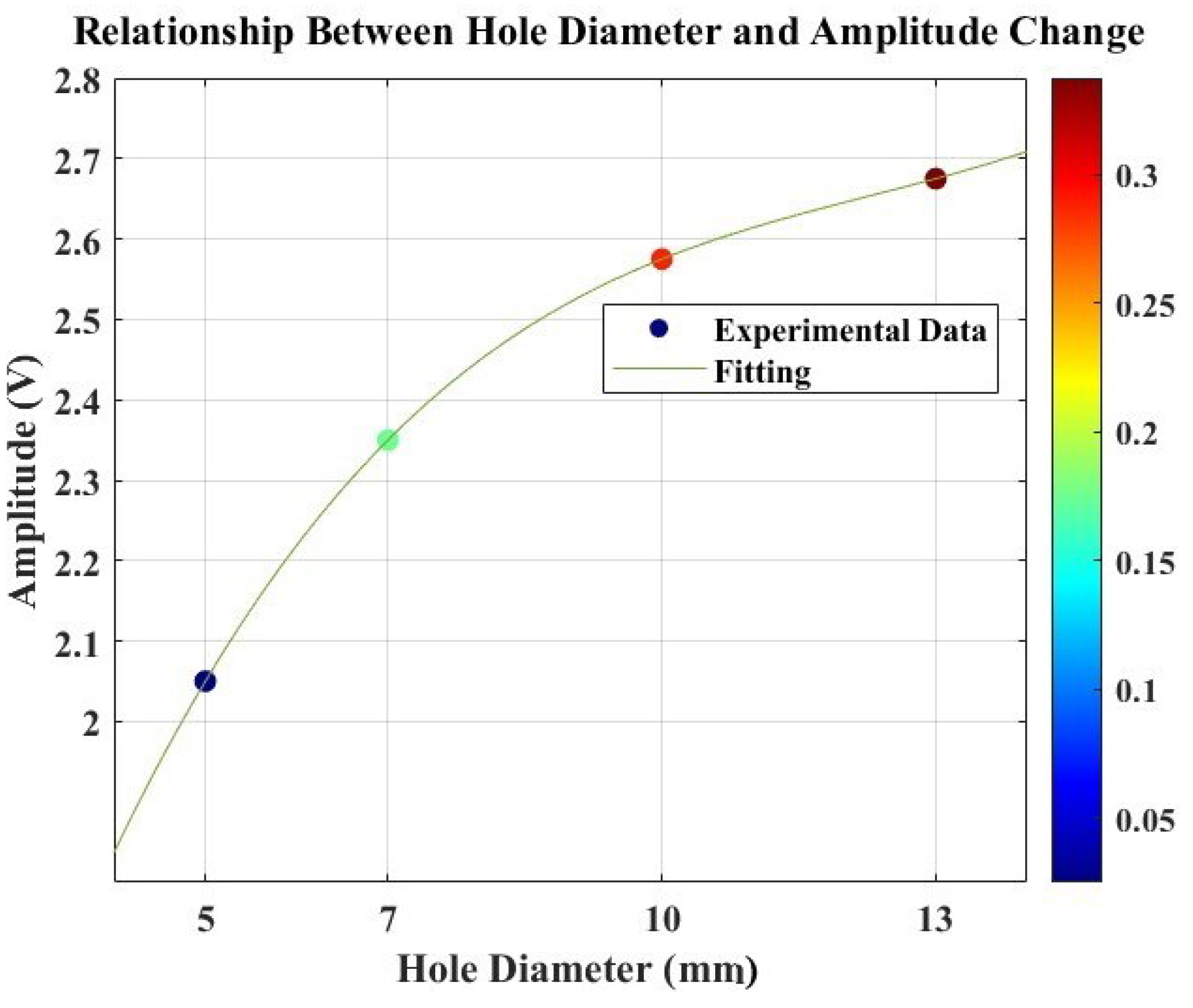
| Hole Diameter [mm] | Amplitude Response [V] | Relative Difference |
|---|---|---|
| 5 | 2.050 | 0.025 |
| 7 | 2.350 | 0.175 |
| 10 | 2.575 | 0.2875 |
| 13 | 2.675 | 0.3375 |
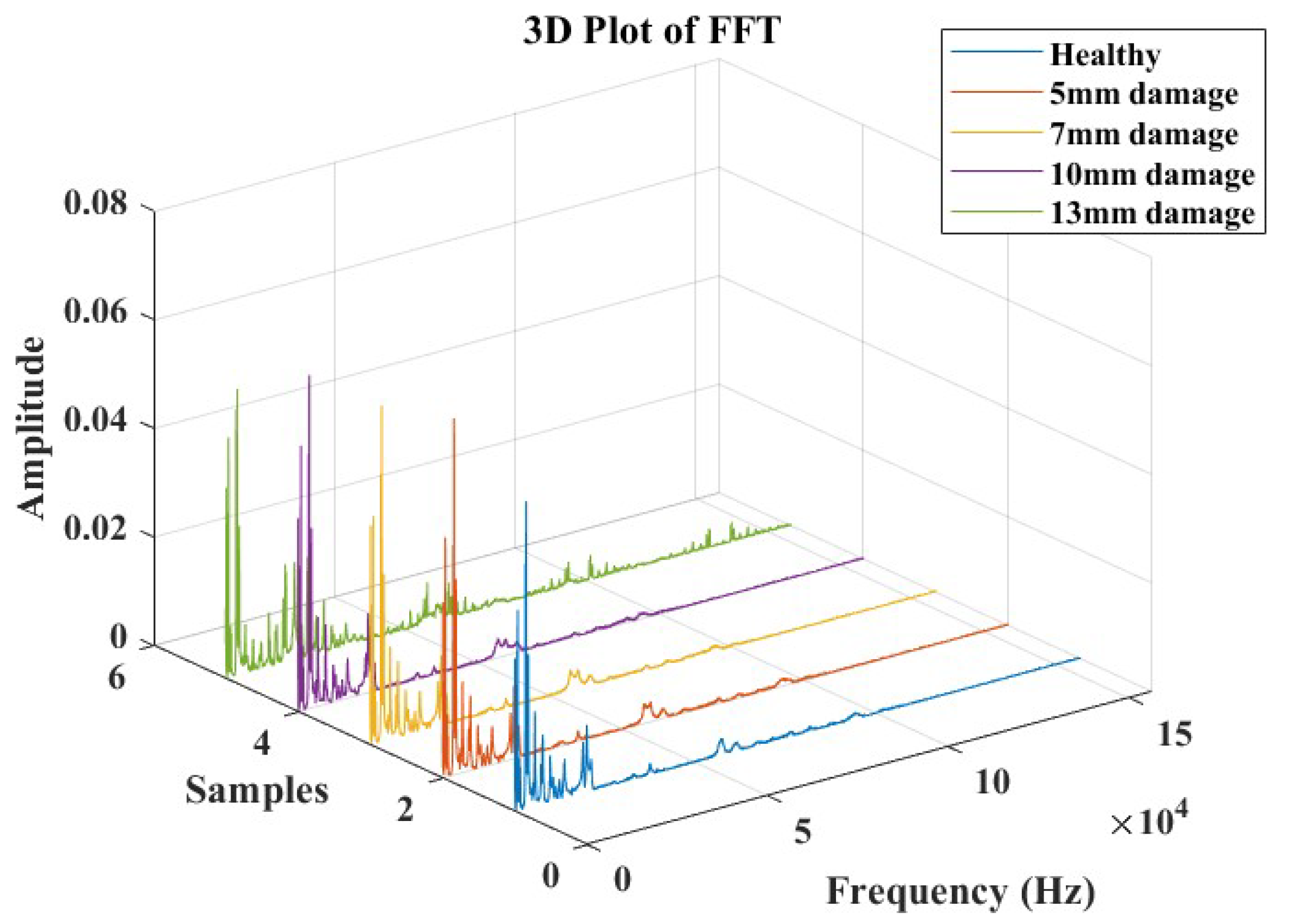
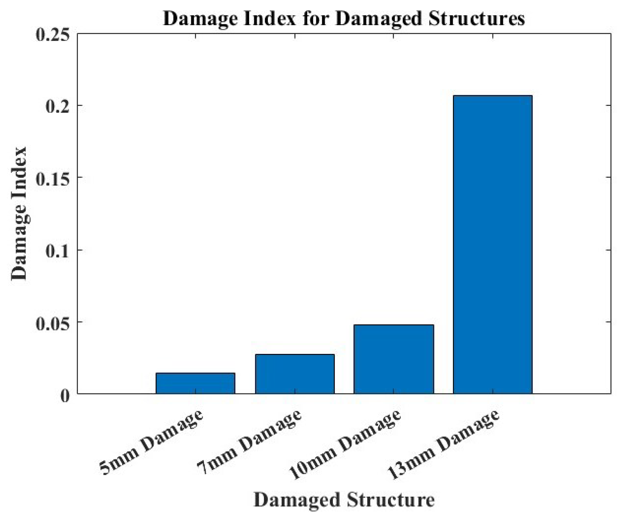
| Hole Diameter [mm] | Peak Frequency | Area under the Curve | Centroid Frequency | Relative Difference—Peak Freq. | Relative Difference—Area | Relative Difference—Centroid Freq. | Damage Indices |
|---|---|---|---|---|---|---|---|
| Baseline | 19,861.7670 | 28.0935 | 29,846.5018 | – | – | – | – |
| 5 | 19,723.4111 | 28.7185 | 30,160.4476 | −0.0070 | 0.0222 | 0.0105 | 0.0144 |
| 7 | 19,600.4280 | 29.3909 | 30,211.4998 | −0.0132 | 0.0462 | 0.0122 | 0.0274 |
| 10 | 19,354.4618 | 30.3196 | 30,556.2719 | −0.0255 | 0.0792 | 0.0238 | 0.0480 |
| 13 | 16,418.2409 | 37.3246 | 31,530.3745 | −0.1734 | 0.3286 | 0.0564 | 0.2066 |
| Hole Diameter [mm] | Centroid Frequency—Simulation | Centroid Frequency—Experiment | % Difference |
|---|---|---|---|
| Intact (Healthy) | 30,224.5970 | 29,846.5018 | 1.3 |
| 5 | 30,607.5207 | 30,160.4476 | 1.5 |
| 7 | 30,750.5275 | 30,211.4998 | 1.8 |
| 13 | 30,947.5353 | 31,530.3745 | 1.9 |
Disclaimer/Publisher’s Note: The statements, opinions and data contained in all publications are solely those of the individual author(s) and contributor(s) and not of MDPI and/or the editor(s). MDPI and/or the editor(s) disclaim responsibility for any injury to people or property resulting from any ideas, methods, instructions or products referred to in the content. |
© 2024 by the authors. Licensee MDPI, Basel, Switzerland. This article is an open access article distributed under the terms and conditions of the Creative Commons Attribution (CC BY) license (https://creativecommons.org/licenses/by/4.0/).
Share and Cite
Langat, R.K.; De Luycker, E.; Cantarel, A.; Rakotondrabe, M. Integration Technology with Thin Films Co-Fabricated in Laminated Composite Structures for Defect Detection and Damage Monitoring. Micromachines 2024, 15, 274. https://doi.org/10.3390/mi15020274
Langat RK, De Luycker E, Cantarel A, Rakotondrabe M. Integration Technology with Thin Films Co-Fabricated in Laminated Composite Structures for Defect Detection and Damage Monitoring. Micromachines. 2024; 15(2):274. https://doi.org/10.3390/mi15020274
Chicago/Turabian StyleLangat, Rogers K., Emmanuel De Luycker, Arthur Cantarel, and Micky Rakotondrabe. 2024. "Integration Technology with Thin Films Co-Fabricated in Laminated Composite Structures for Defect Detection and Damage Monitoring" Micromachines 15, no. 2: 274. https://doi.org/10.3390/mi15020274
APA StyleLangat, R. K., De Luycker, E., Cantarel, A., & Rakotondrabe, M. (2024). Integration Technology with Thin Films Co-Fabricated in Laminated Composite Structures for Defect Detection and Damage Monitoring. Micromachines, 15(2), 274. https://doi.org/10.3390/mi15020274