
Improving the Quality of Laser Drilling by Assisted Process Methods of Static Solution and Mist Blowing

Abstract
:1. Introduction
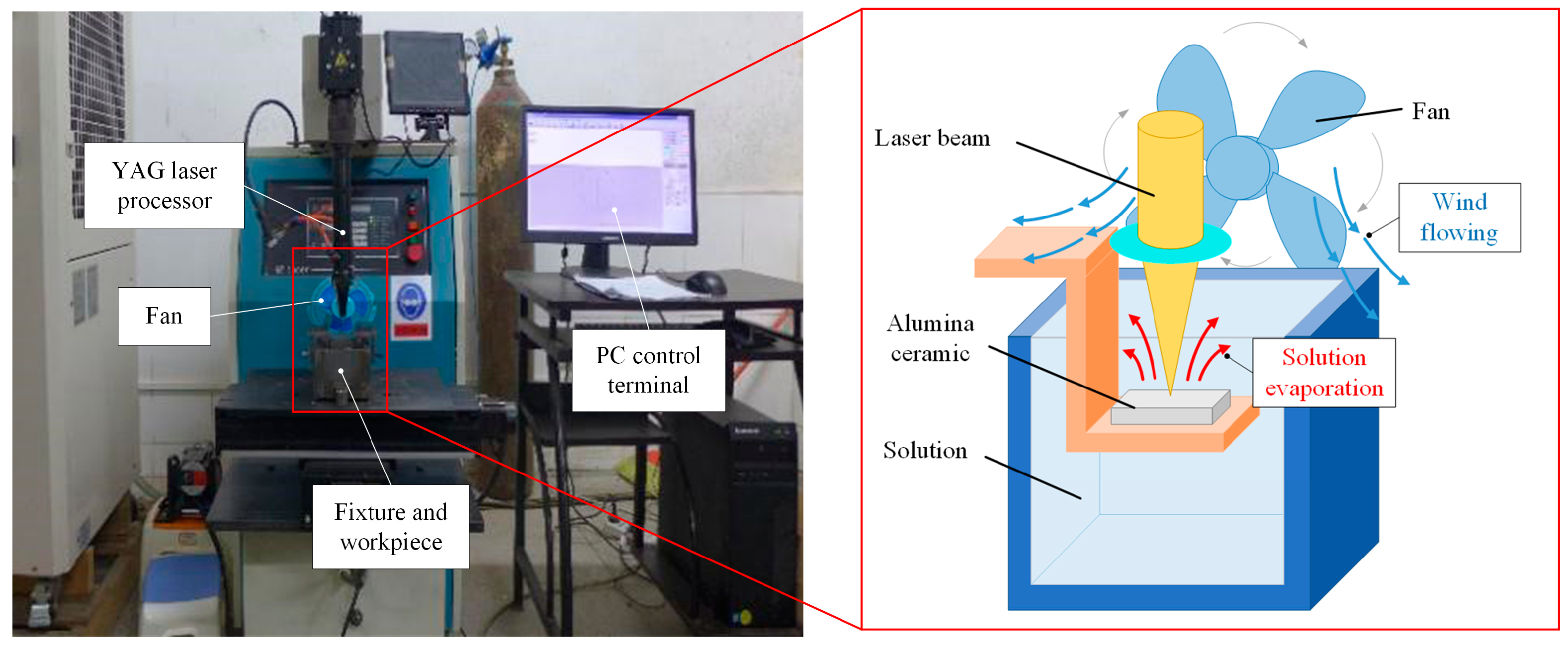
2. Materials and Methods
3. Results and Discussion
3.1. Influence of Mist-Blowing Method on Hole Quality
3.1.1. Taper
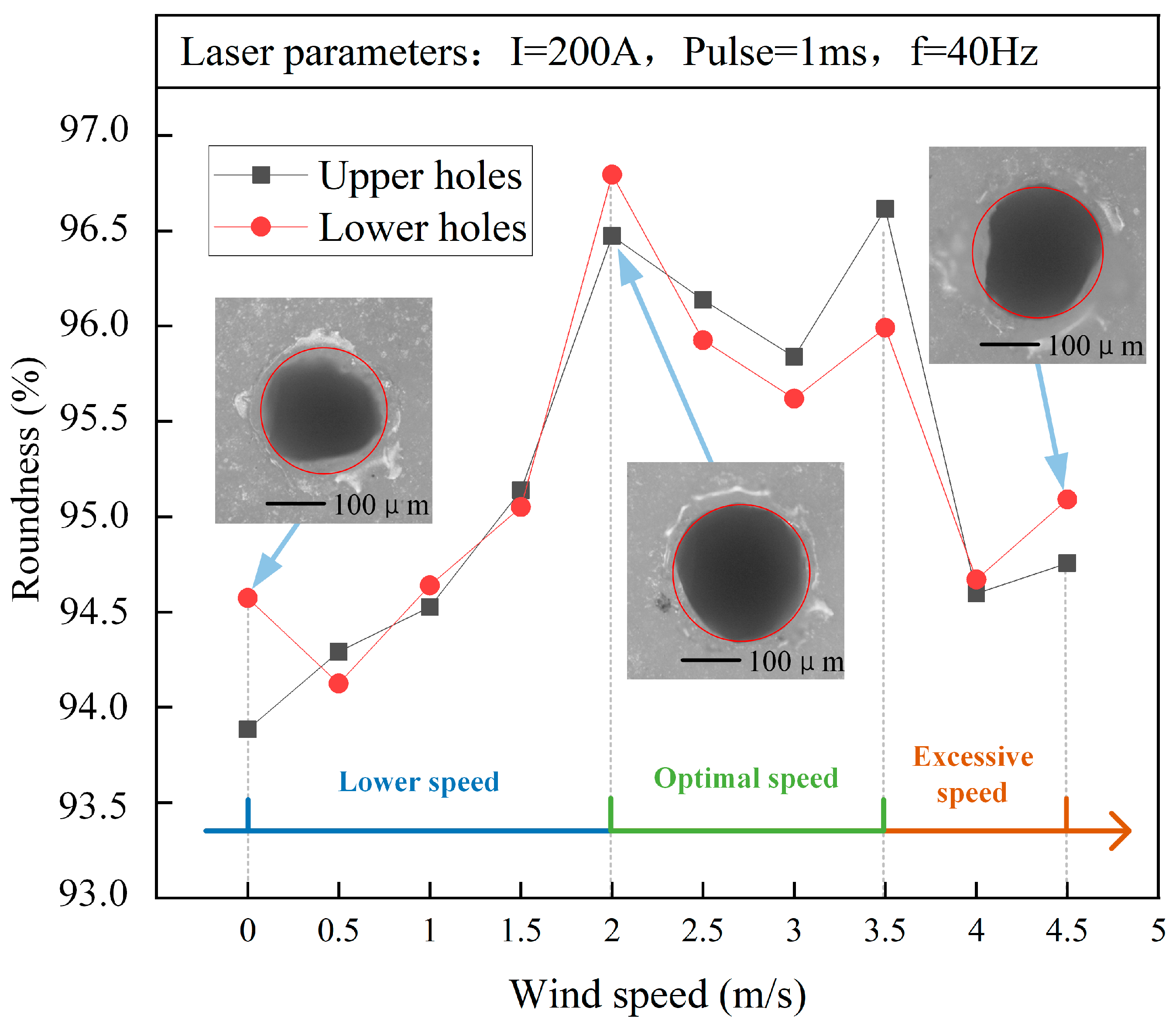
3.1.2. Roundness
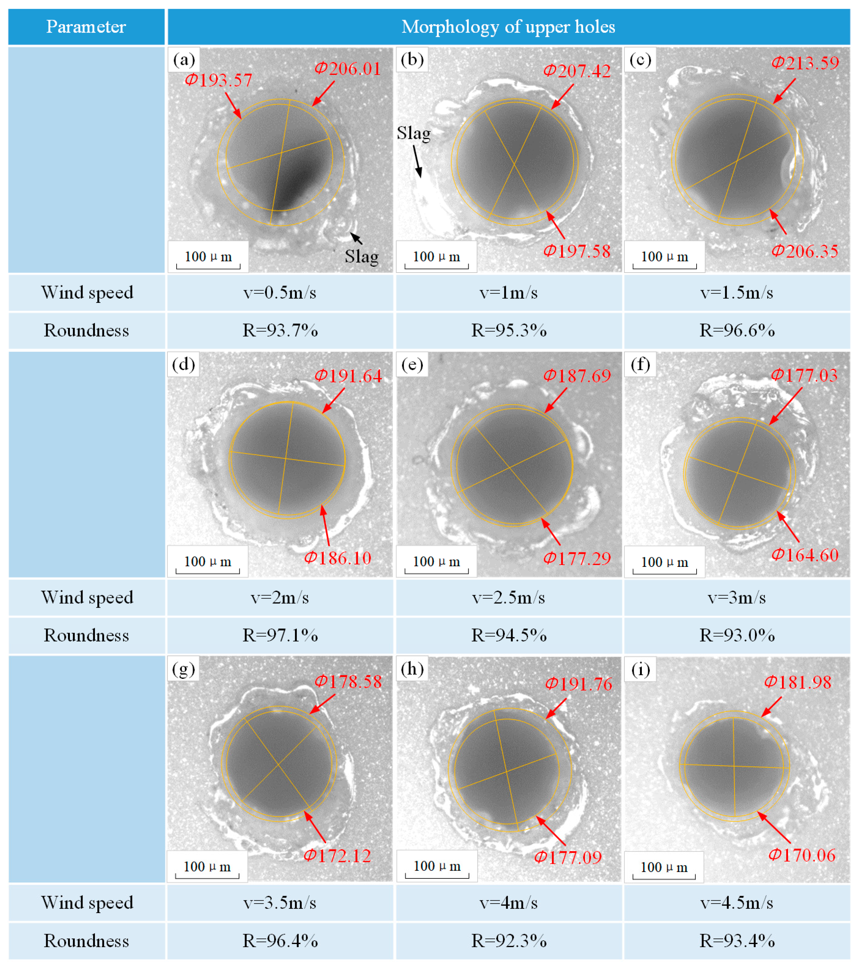
3.1.3. Morphology Quality of Holes
3.2. Influence of Drilling Environments on Hole Quality
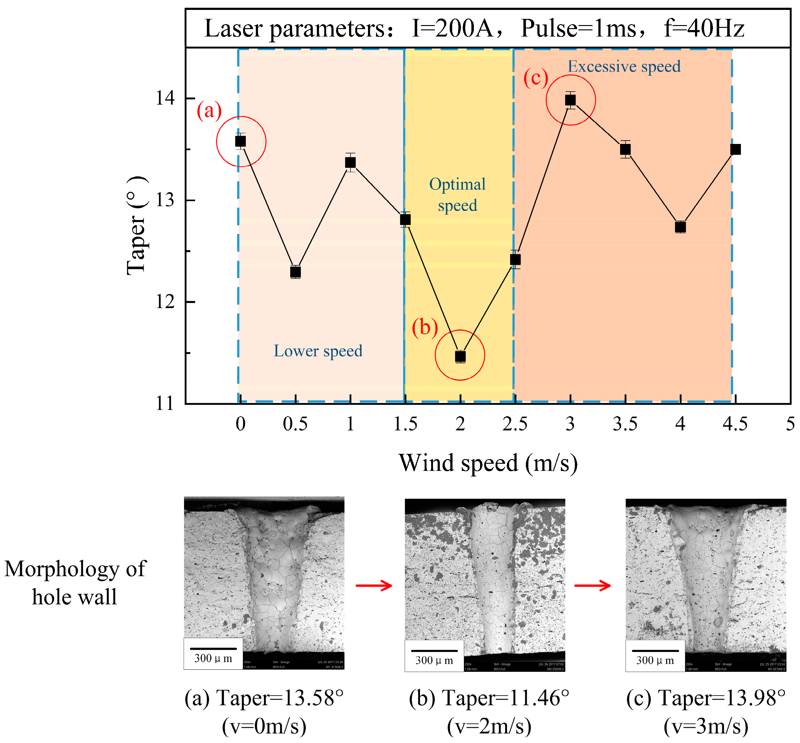
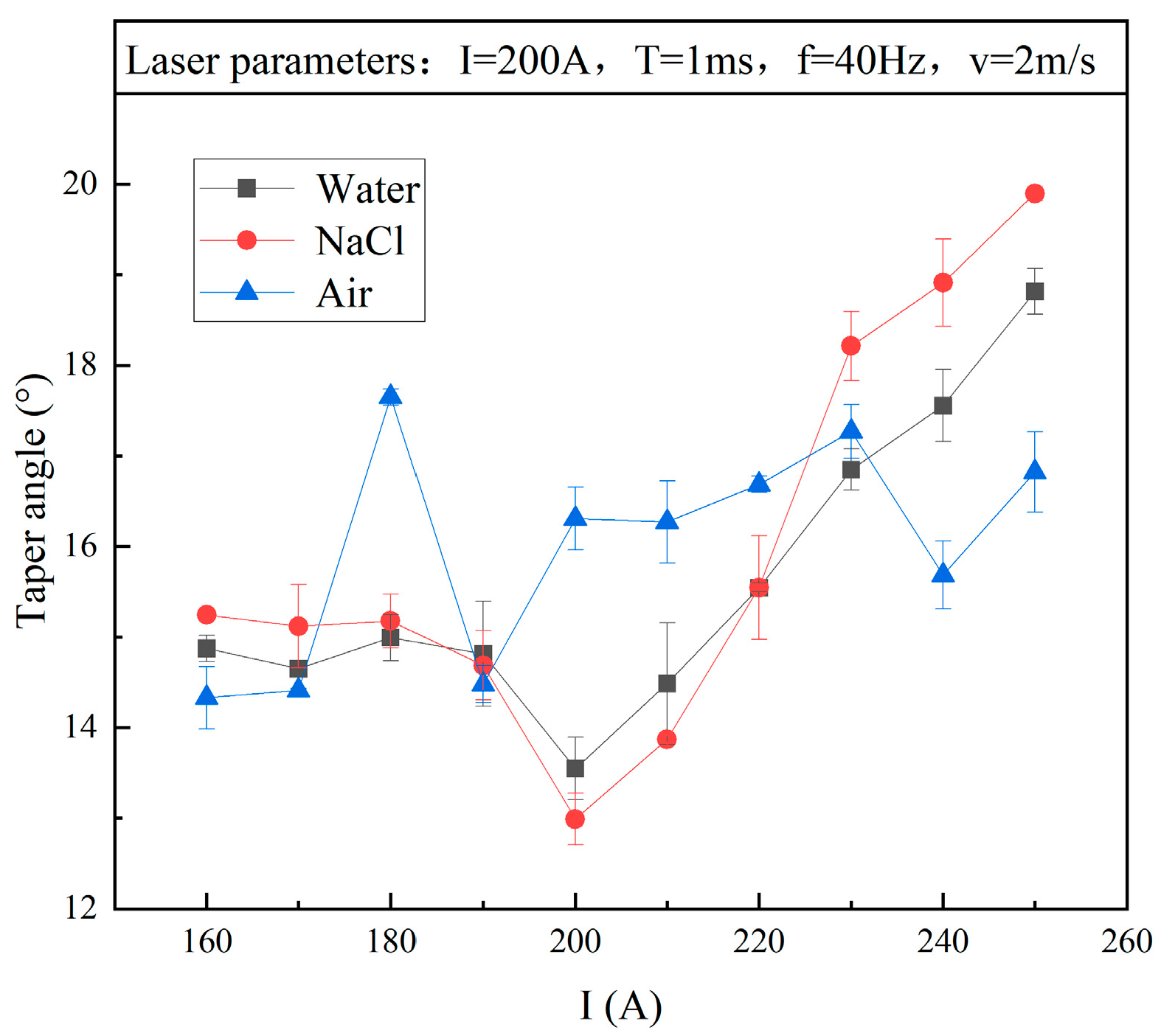
3.2.1. Taper
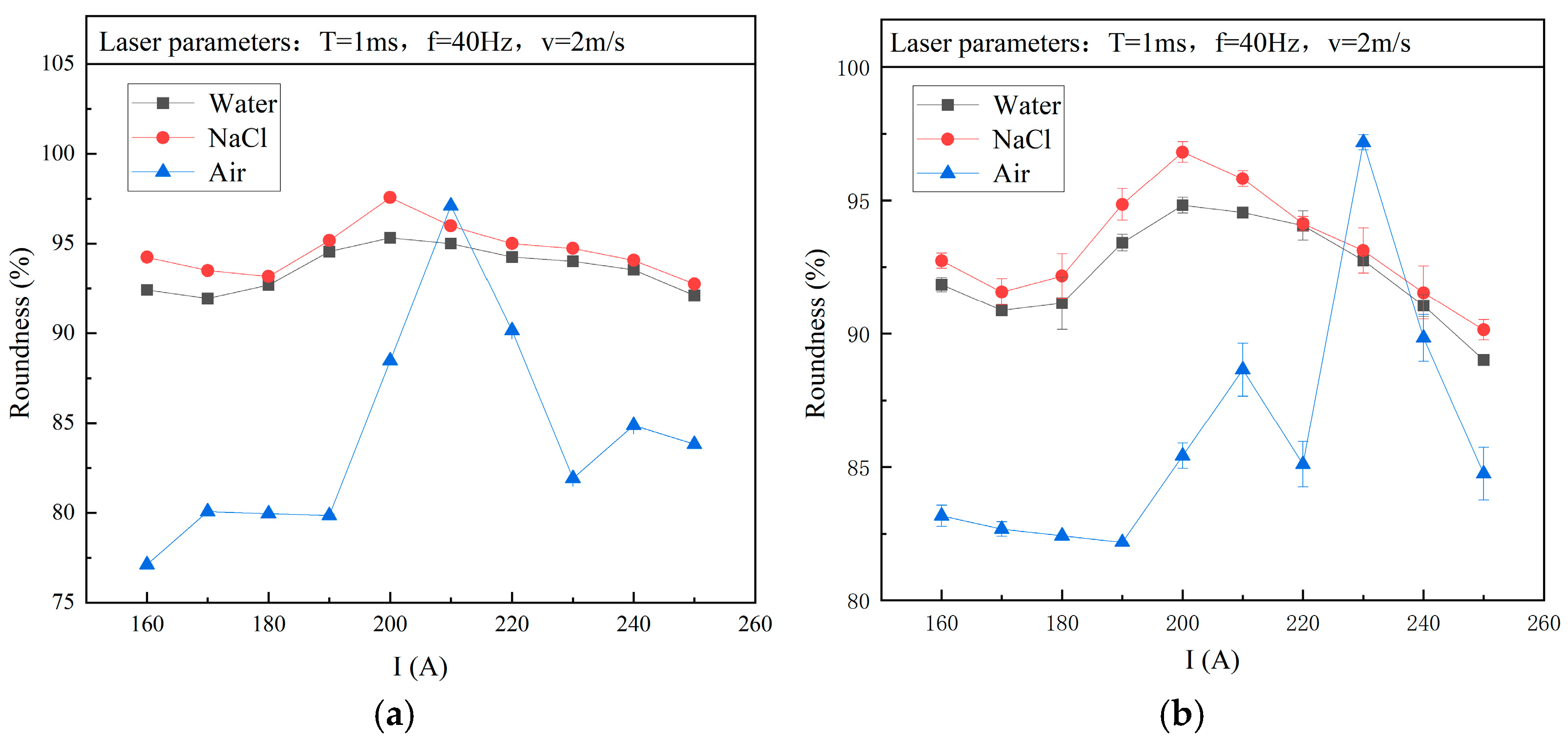
3.2.2. Roundness
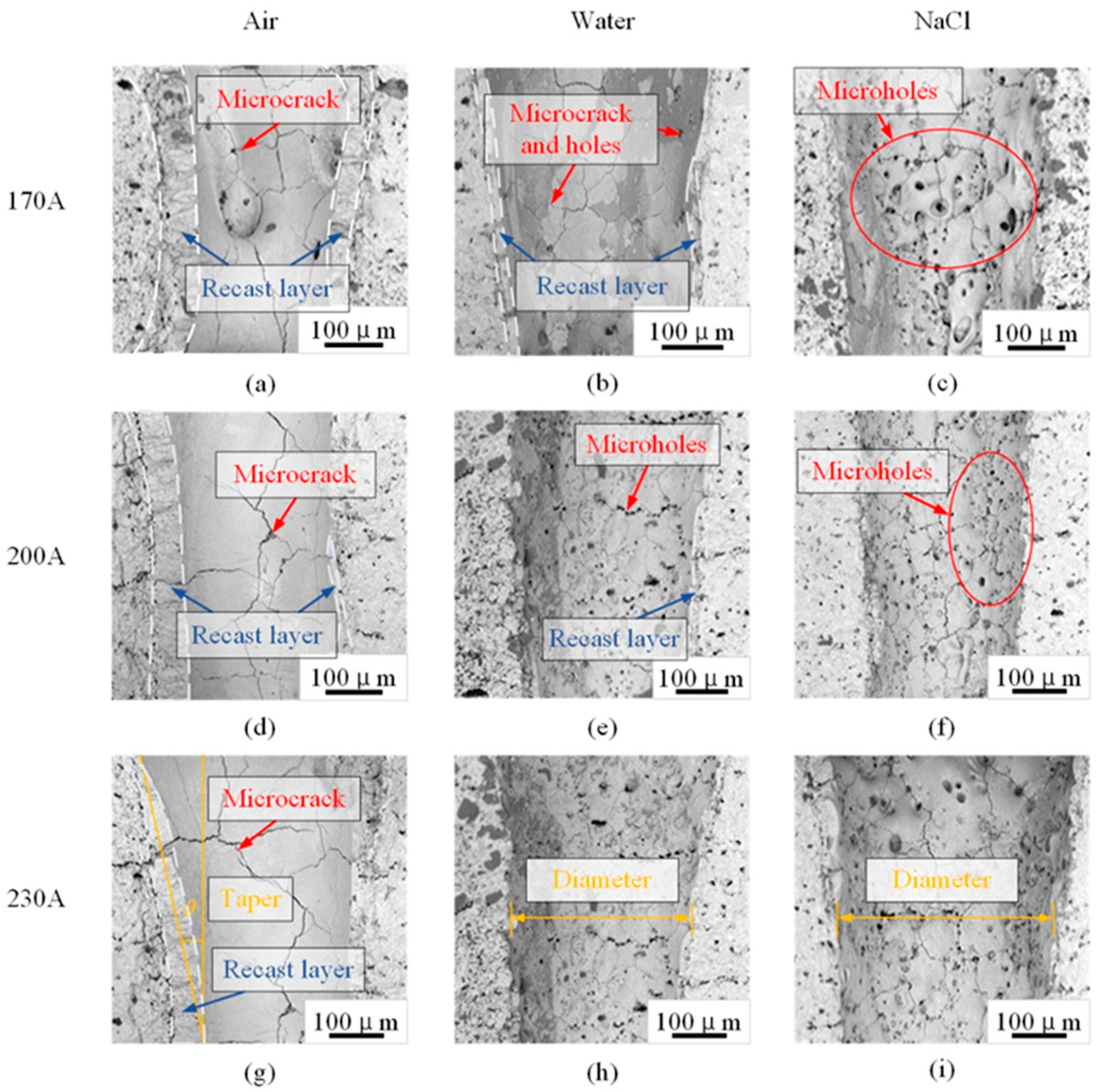
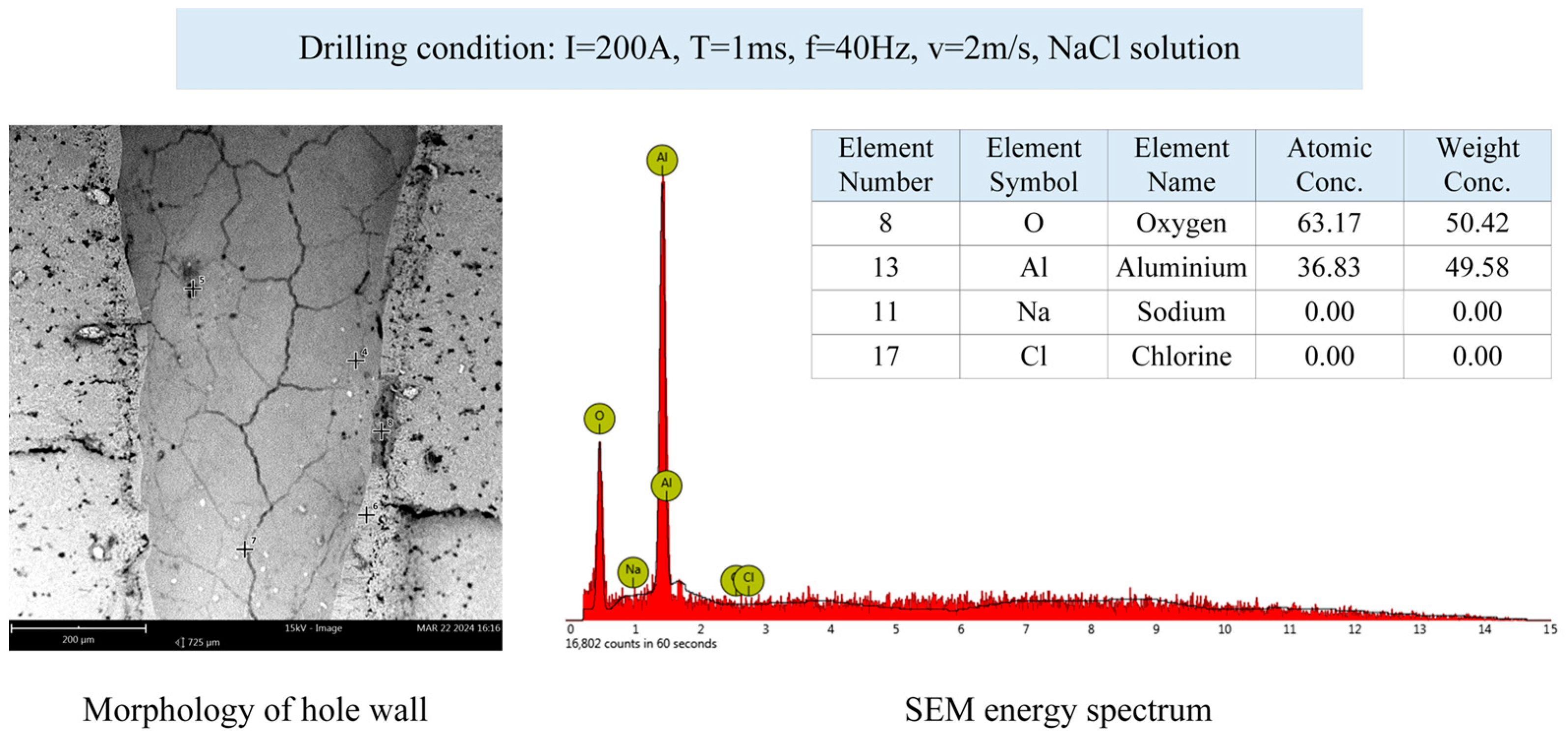
3.2.3. Morphology of the Inner Wall
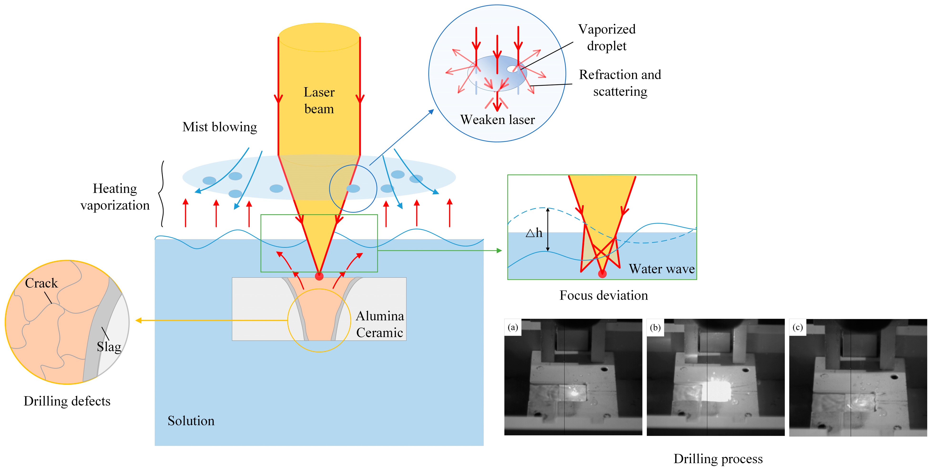
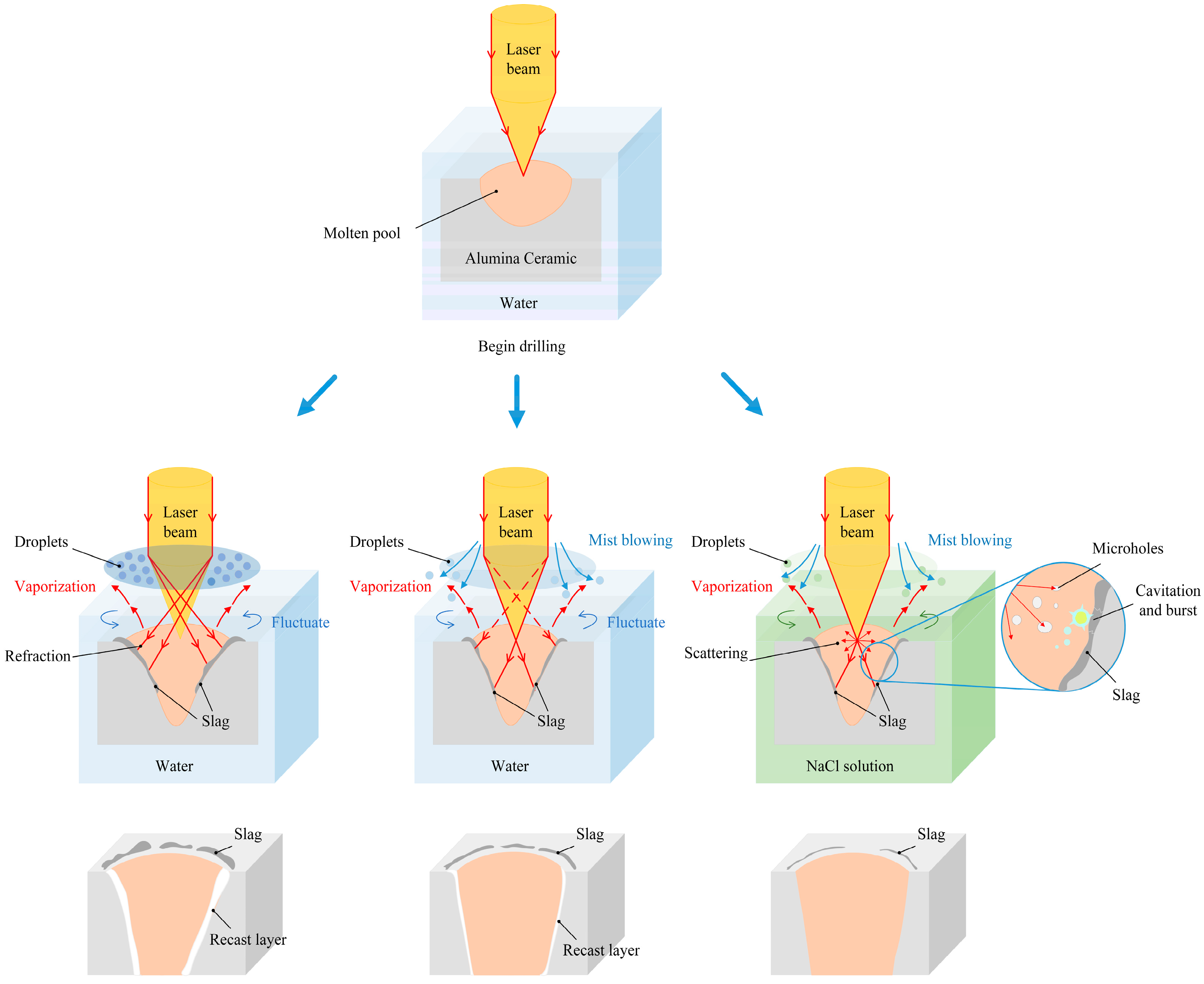
3.2.4. Drilling Mechanism and Process
4. Conclusions
Author Contributions
Funding
Data Availability Statement
Conflicts of Interest
References
- Hao, H. Research status and development trend of bulletproof ceramic materials. J. Chin. Ceram. 2023, 59, 11–15. [Google Scholar]
- Zhang, W.Y. Research and application of armor protective ceramic materials. J. Ceram. 2020, 8, 16–20. [Google Scholar]
- Dong, X.Y.; Shen, Z.; Yue, Z.J. Research and application progress of ceramic 3D printing in the medical field. J. Chin. Med. Equip. 2023, 20, 186–191. [Google Scholar]
- Mohammadi, H.; Beddu, S. Advances in silicon nitride ceramic biomaterials for dental applications—A review. J. Mater. Res. Technol. 2024, 28, 2778–2791. [Google Scholar] [CrossRef]
- Paulo, H.; Chibério; Hugo, P.A. Al2O3 dielectric ceramic tapes containing hBN for applications on high-frequency substrates. Ceram. Int. 2024, 50, 2864–2870. [Google Scholar]
- Kriegler, J.; Hille, L. Scaling up picosecond laser ablation of a LATGP-type glass-ceramic solid electrolyte for all-solid-state battery production. J. Manuf. Process. 2023, 106, 188–201. [Google Scholar] [CrossRef]
- Zanet, A.D.; Casalegno, V. Laser surface texturing of ceramics and ceramic composite materials—A review. Ceram. Int. 2021, 47, 7307–7320. [Google Scholar] [CrossRef]
- Zheng, C.L.; Zhao, K.; Shen, H. Crack behavior in ultrafast laser drilling of thermal barrier coated nickel superalloy. J. Mater. Process. Technol. 2020, 282, 116678. [Google Scholar] [CrossRef]
- Wang, H.J.; Yang, T. A review on laser drilling and cutting of silicon. J. Eur. Ceram. Soc. 2021, 41, 4997–5015. [Google Scholar] [CrossRef]
- Márquez Aguilar, P.A.; Vlasova, M.; Bernal, E.M. Features of laser drilling of porous aluminosilicate ceramics. MRS Adv. 2020, 5, 3045–3054. [Google Scholar] [CrossRef]
- Min, C.Q.; Yang, X.B. Micromachining porous alumina ceramic for high quality trimming of turbine blade cores via double femtosecond laser scanning. Ceram. Int. 2021, 47, 461–469. [Google Scholar] [CrossRef]
- Saini, S.K.; Dubey, A.K. Study of material characteristics in laser trepan drilling of ZTA. J. Manuf. Process 2019, 44, 349–358. [Google Scholar] [CrossRef]
- Saini, S.K.; Dubey, A.K. Parameters optimization for microcrack width in laser trepanned hole. Mater. Today Proc. 2021, 44, 3055–3058. [Google Scholar] [CrossRef]
- Zhang, H.; Xu, J.W.; Wang, J.M. Investigation of a novel hybrid process of laser drilling assisted with jet electrochemical machining. Opt. Lasers Eng. 2009, 47, 1242–1249. [Google Scholar] [CrossRef]
- Jia, X.S.; Li, Z. Study of the dynamics of material removal processes in combined pulse laser drilling of alumina ceramic. Opt. Laser Technol. 2023, 160, 109053. [Google Scholar] [CrossRef]
- Feng, D.C.; Shen, H. Hole quality control in underwater drilling of yttria-stabilized zirconia using a picosecond laser. Opt. Laser Technol. 2019, 113, 141–149. [Google Scholar] [CrossRef]
- Zahrani, E.G.; Azarhoushang, B. Ablation characteristics of picosecond laser single point drilling of Si3N4 under dry and water medium. Procedia CIRP 2020, 95, 938–943. [Google Scholar] [CrossRef]
- Liang, C.; Li, Z. Laser drilling of alumina ceramic substrates: A review. Opt. Laser Technol. 2023, 167, 109828. [Google Scholar] [CrossRef]
- Zhou, X.; Duan, J.; Chen, H. Experimental study on water assisted laser on recast layer drilling of Al2O3 ceramics. J. Laser Technol. 2018, 42, 271–275. [Google Scholar]
- Ren, N.F.; Xia, K.B. Water-assisted femtosecond laser drilling of alumina ceramics. Ceram. Int. 2021, 47, 11465–11473. [Google Scholar] [CrossRef]
- Ren, N.F.; Gao, F.Q.; Wang, H.X. Water-induced effect on femtosecond laser layered ring trepanning in silicon carbide ceramic sheets using low-to-high pulse repetition rate. Opt. Commun. 2021, 496, 127040. [Google Scholar] [CrossRef]
- Bao, L.; Wang, Y.F.; Wang, R.J. Study on anodic dissolution behavior and surface evolution of laser-drilled Ni-based superalloys during electrochemical post-processing. Electrochim. Acta 2024, 473, 143471. [Google Scholar] [CrossRef]
- Zhang, H.; Xu, J.W.; Wang, J.M. Experimental study on neutral salt solution assisted laser processing. J. Chinese Laser 2008, 11, 1836–1840. [Google Scholar] [CrossRef]
- Li, G.L.; Hu, S.S.; Tang, H.Q. Laser repeat drilling of alumina ceramics in static water. Int. J. Adv. Manuf. Technol. 2018, 96, 2885–2891. [Google Scholar] [CrossRef]
- Li, G.L.; Shi, D.Y.; Hu, S.S. Research on the mechanism of laser drilling alumina ceramics in shallow water. Int. J. Adv. Manuf. Technol. 2022, 118, 3631–3639. [Google Scholar] [CrossRef]
- Zhang, H.; Xu, J.W. Research on laser mechanical effects in neutral salt solution. J. Appl. Laser 2009, 4, 4. [Google Scholar]


| Parameters | Values |
|---|---|
| Maximum power of current output | 12 KW |
| Average output power | 300 W |
| Maximum single-pulse output energy of laser beam | 120 J |
| Wavelength | 1064 nm |
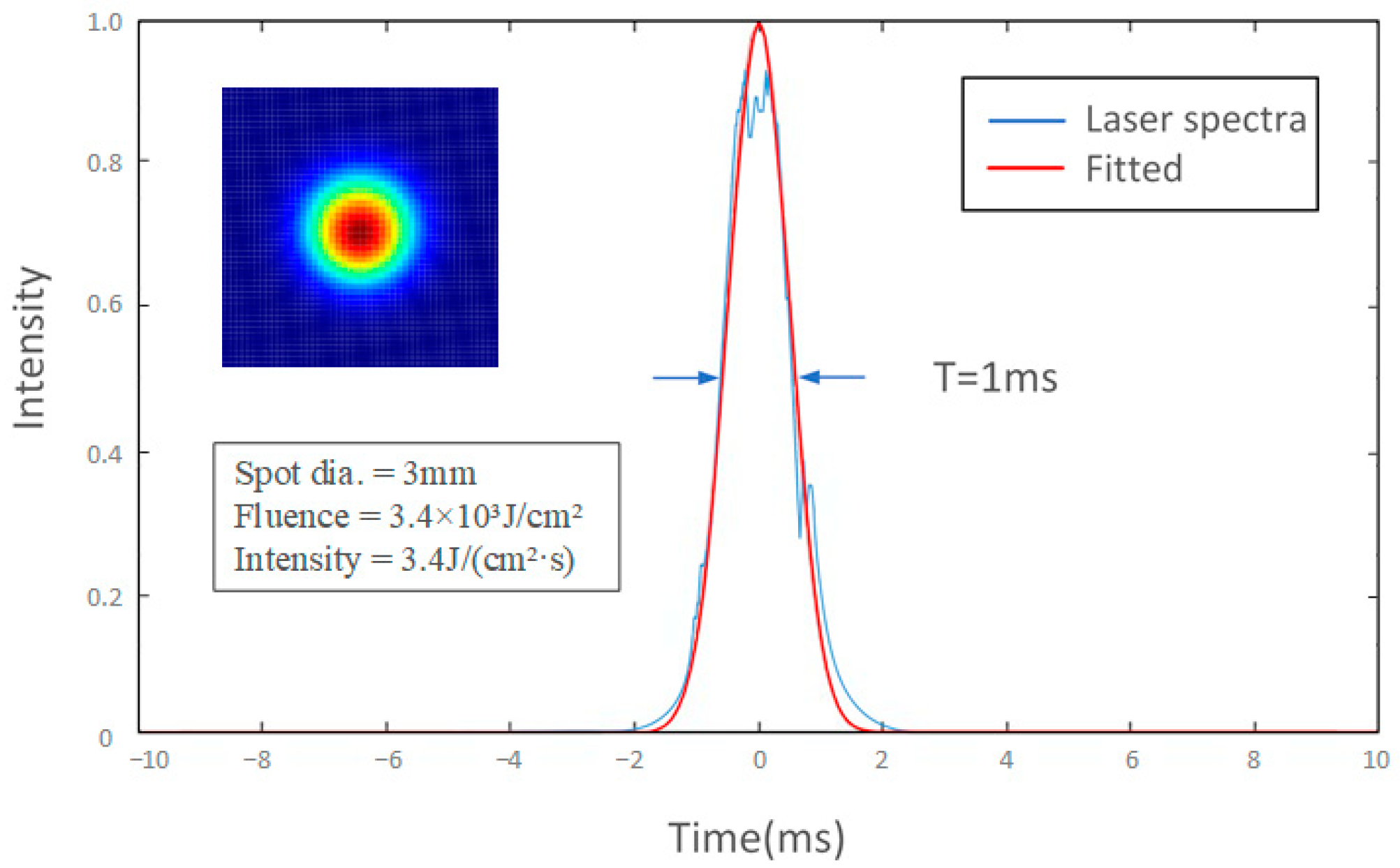
| Pulse width (T) | 1 ms |
| Frequency (f) | 40 Hz |
| Focusing position | −0.5 mm |
| Spot diameter | 3 mm |
| Parameters | Values |
|---|---|
| Drilling environment | Air, water, NaCl |
| Wind speed (v) | 0, 0.5, 1, 1.5, 2, 2.5, 3, 3.5, 4, 4.5 (m/s) |
| Laser current (I) | 170 A, 200 A, 230 A |
| Drilling depth (h) | 1 mm |
Disclaimer/Publisher’s Note: The statements, opinions and data contained in all publications are solely those of the individual author(s) and contributor(s) and not of MDPI and/or the editor(s). MDPI and/or the editor(s) disclaim responsibility for any injury to people or property resulting from any ideas, methods, instructions or products referred to in the content. |
© 2024 by the authors. Licensee MDPI, Basel, Switzerland. This article is an open access article distributed under the terms and conditions of the Creative Commons Attribution (CC BY) license (https://creativecommons.org/licenses/by/4.0/).
Share and Cite
Tao, Y.; Wang, Z.; Hu, S.; Feng, Y.; Yang, F.; Li, G. Improving the Quality of Laser Drilling by Assisted Process Methods of Static Solution and Mist Blowing. Micromachines 2024, 15, 515. https://doi.org/10.3390/mi15040515
Tao Y, Wang Z, Hu S, Feng Y, Yang F, Li G. Improving the Quality of Laser Drilling by Assisted Process Methods of Static Solution and Mist Blowing. Micromachines. 2024; 15(4):515. https://doi.org/10.3390/mi15040515
Chicago/Turabian StyleTao, Yuan, Zhiwei Wang, Shanshan Hu, Yufei Feng, Fan Yang, and Guangliang Li. 2024. "Improving the Quality of Laser Drilling by Assisted Process Methods of Static Solution and Mist Blowing" Micromachines 15, no. 4: 515. https://doi.org/10.3390/mi15040515
APA StyleTao, Y., Wang, Z., Hu, S., Feng, Y., Yang, F., & Li, G. (2024). Improving the Quality of Laser Drilling by Assisted Process Methods of Static Solution and Mist Blowing. Micromachines, 15(4), 515. https://doi.org/10.3390/mi15040515