MEMS Varifocal Optical Elements for Focus Control


Abstract
:1. Introduction
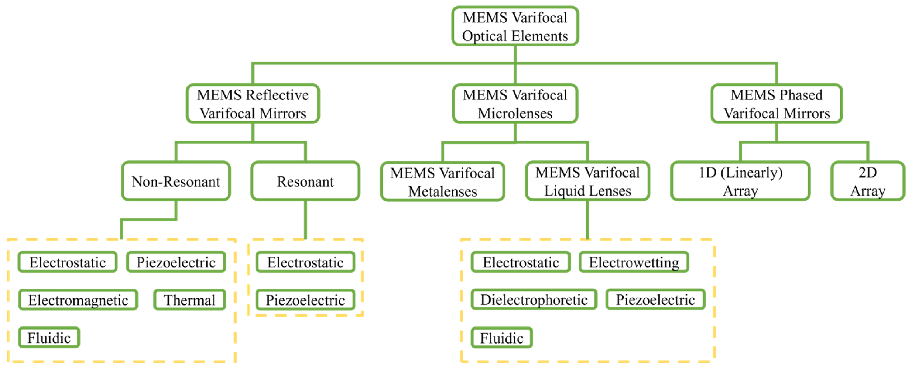
2. MEMS Varifocal Optical Elements
2.1. Physics Principle, Micro-Actuation Mechanism, and Evaluation Metrics
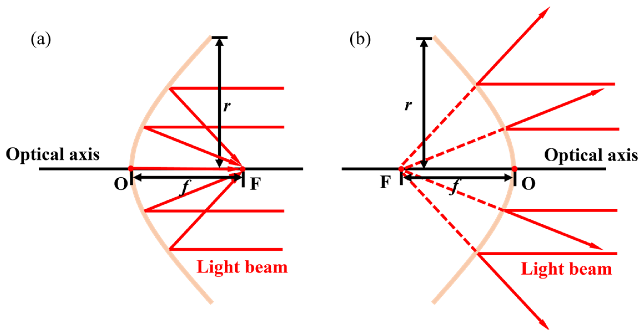
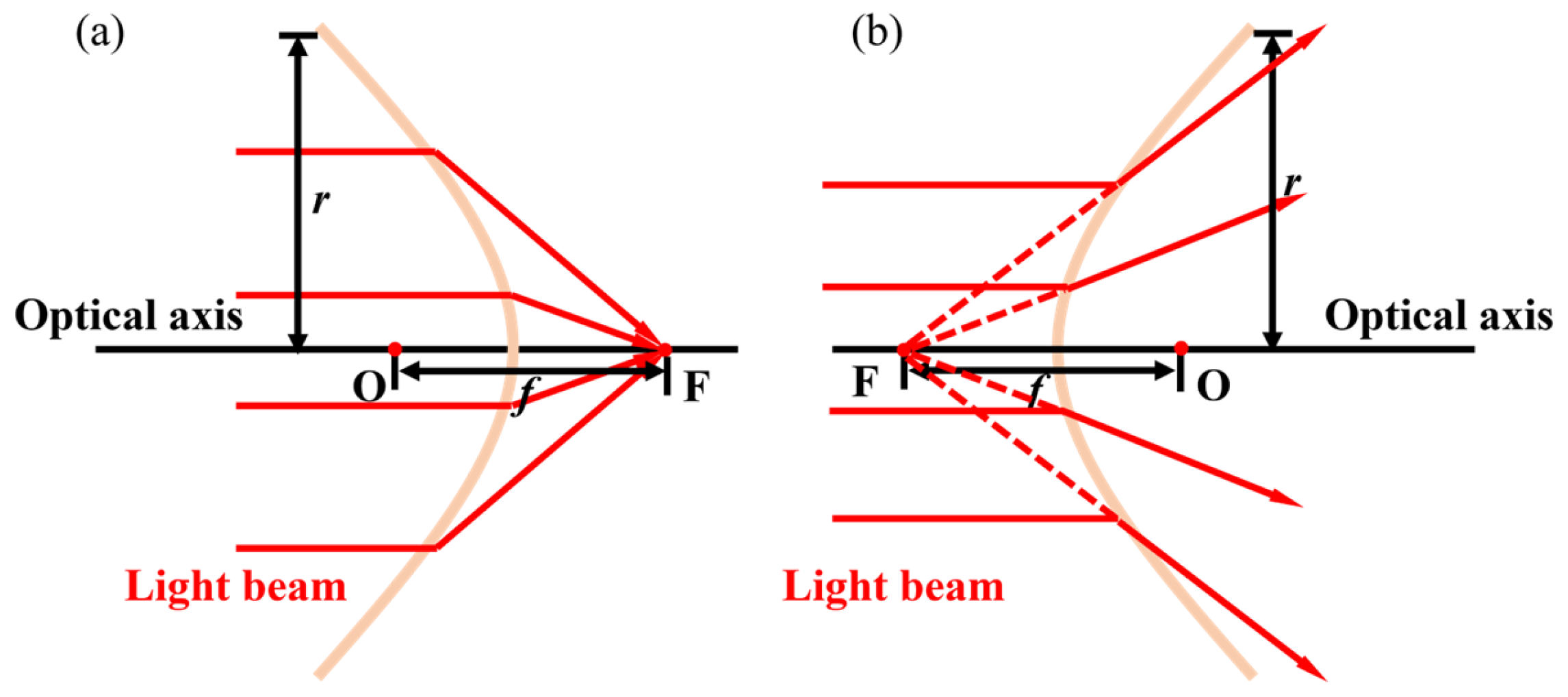
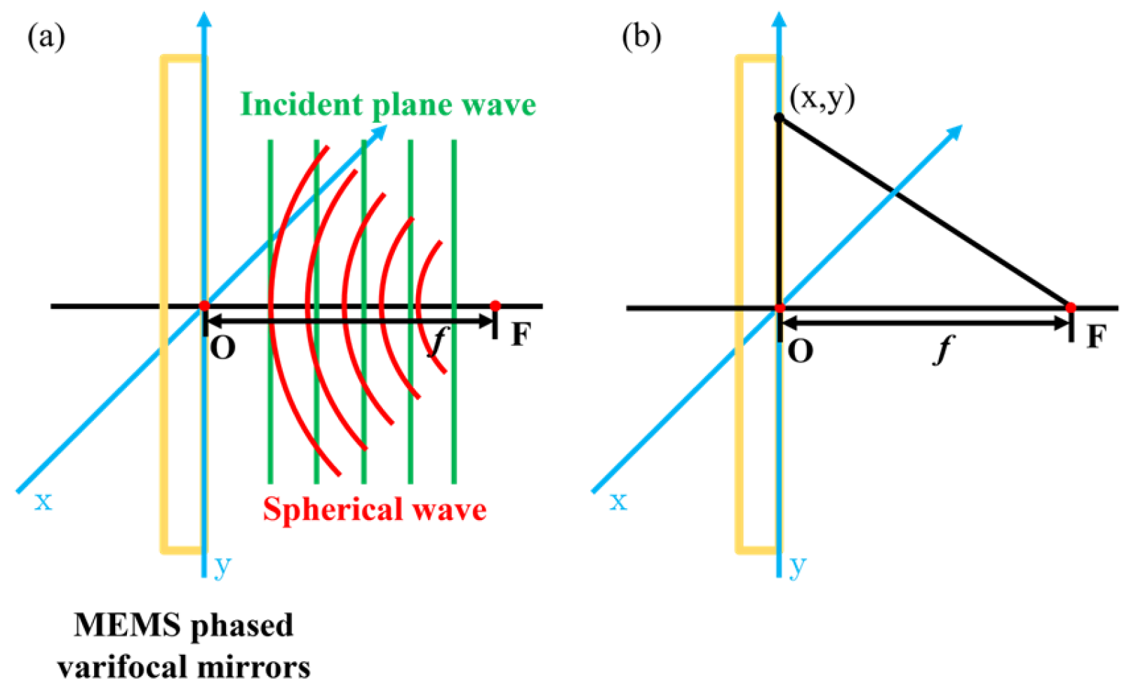
2.1.1. Physics Principle
MEMS Reflective Varifocal Mirrors
MEMS Varifocal Microlenses
MEMS Phased Varifocal Mirrors
2.1.2. Micro-Actuation Mechanism
2.1.3. Evaluation Metrics
2.2. MEMS Reflective Varifocal Mirrors
2.2.1. Non-Resonant
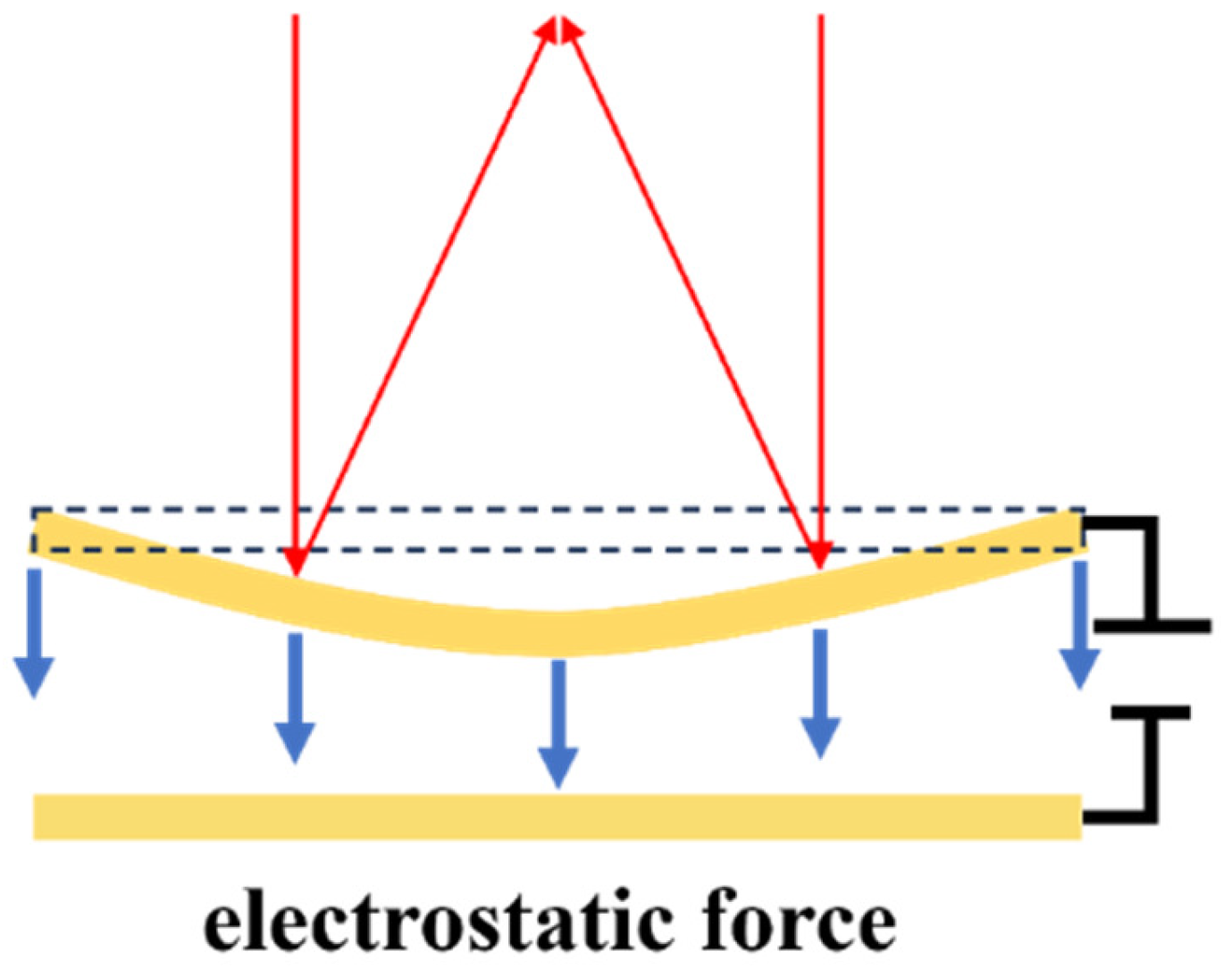
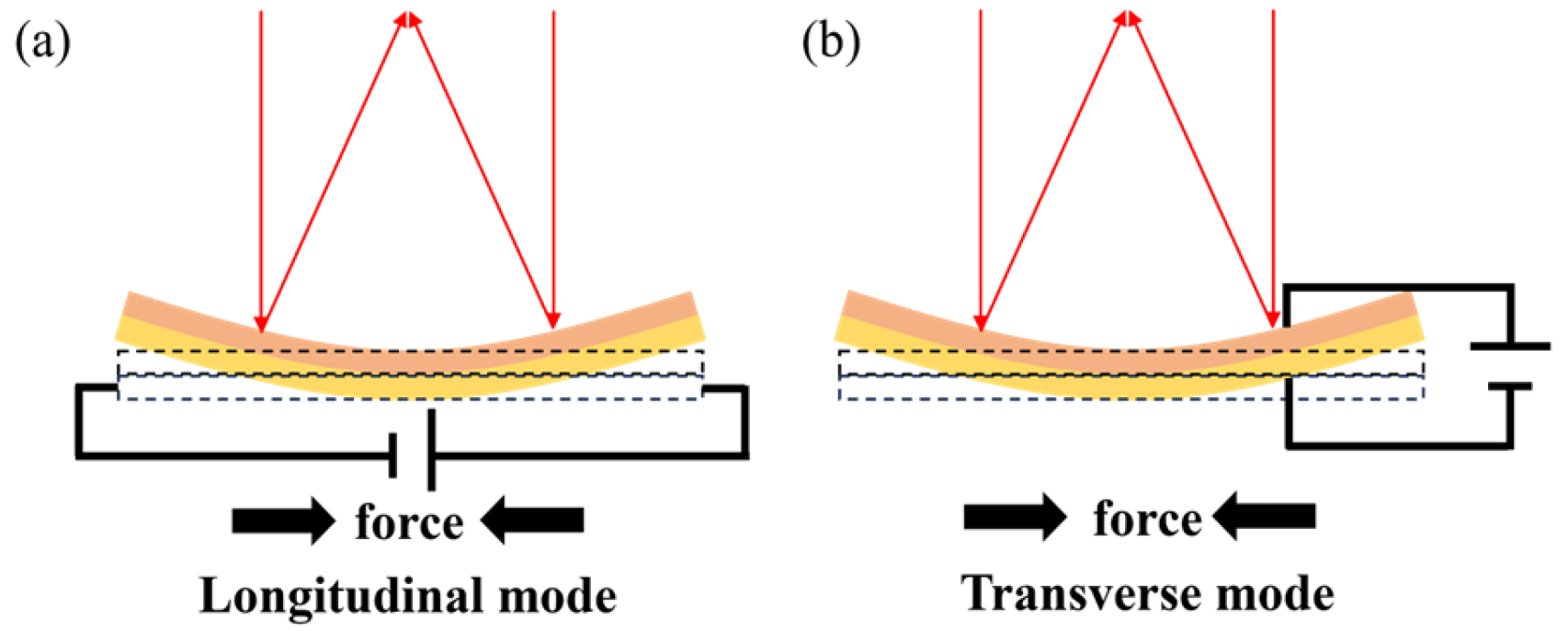
Electrostatic Actuation
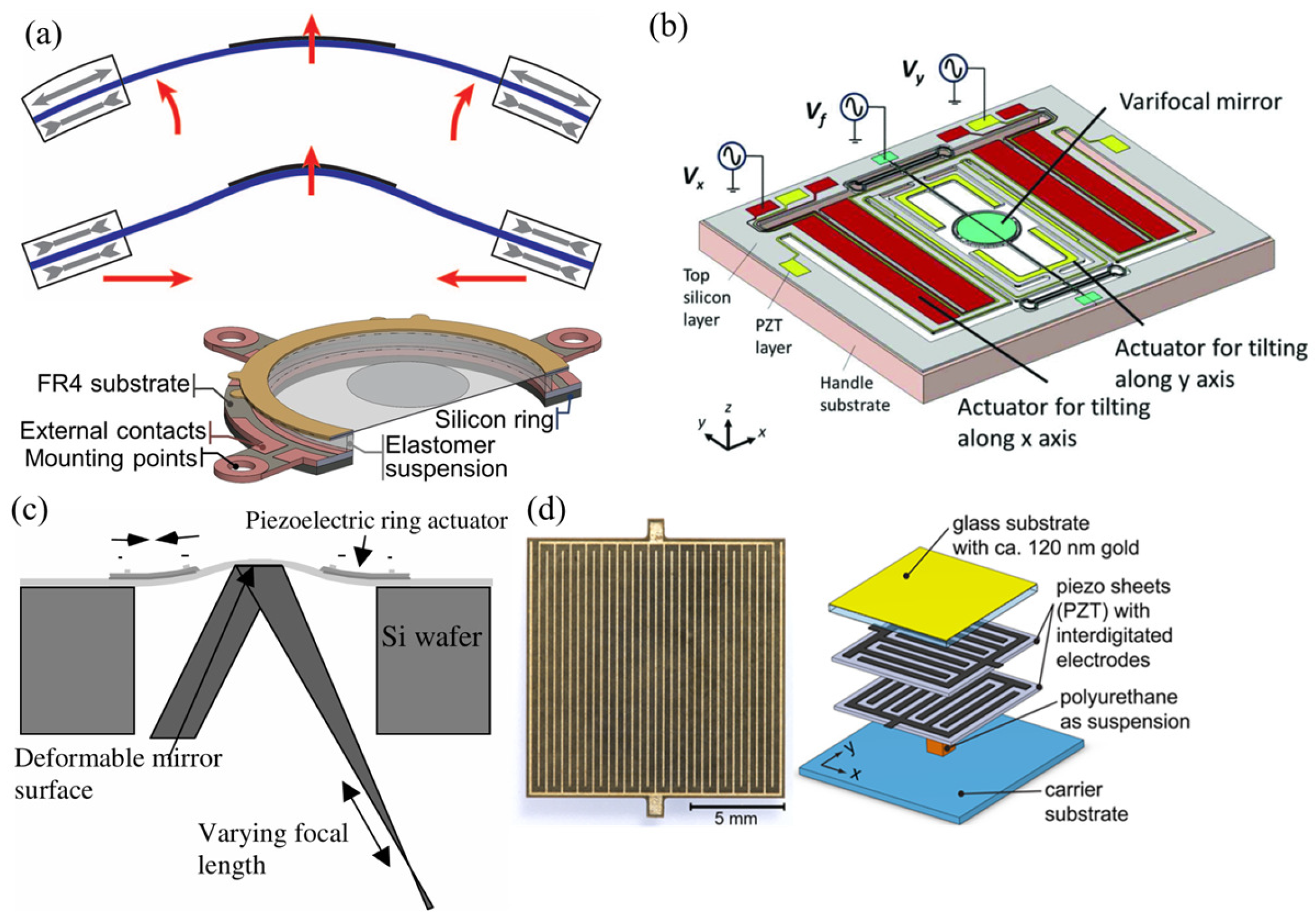
Piezoelectric Actuation
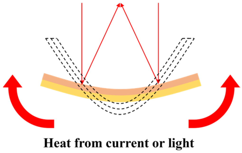
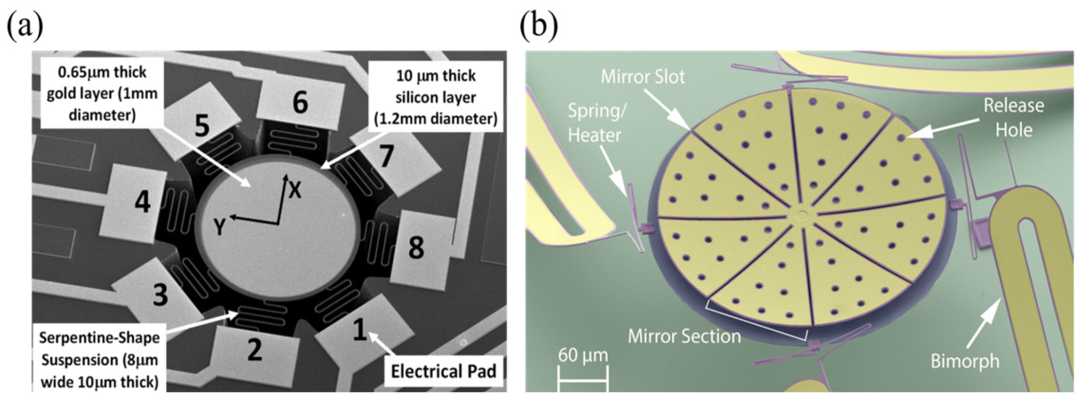
Thermal Actuation
Electromagnetic Actuation
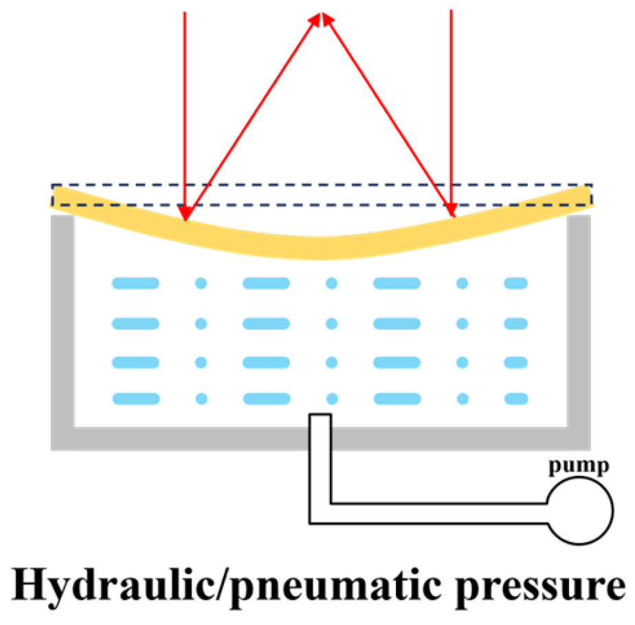
Fluidic Actuation
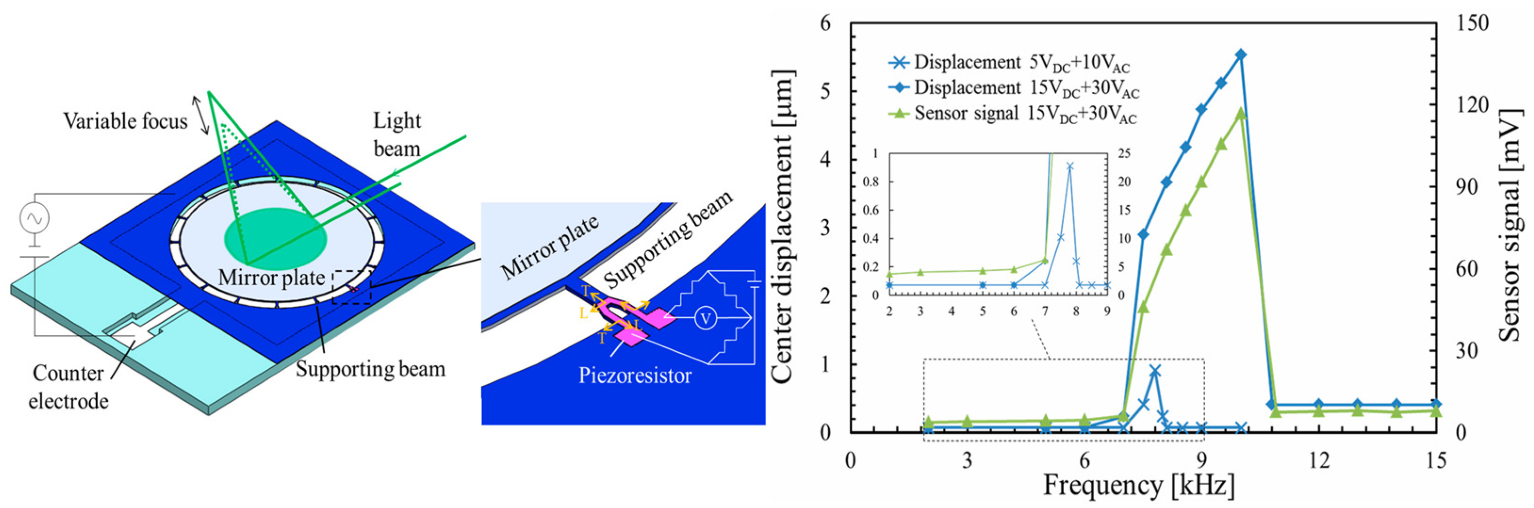
2.2.2. Resonant
2.3. MEMS Varifocal Microlenses
2.3.1. MEMS Varifocal Metalenses
2.3.2. MEMS Varifocal Liquid Lenses
Electrostatic Type
Electrowetting Type
Dielectrophoretic Type
Piezoelectric Type
Fluidic Type
2.4. MEMS Phased Varifocal Mirrors
2.5. Industrial Commercial Products
3. Applications
3.1. Confocal Optical Instruments
3.2. Optical Coherence Tomography (OCT)
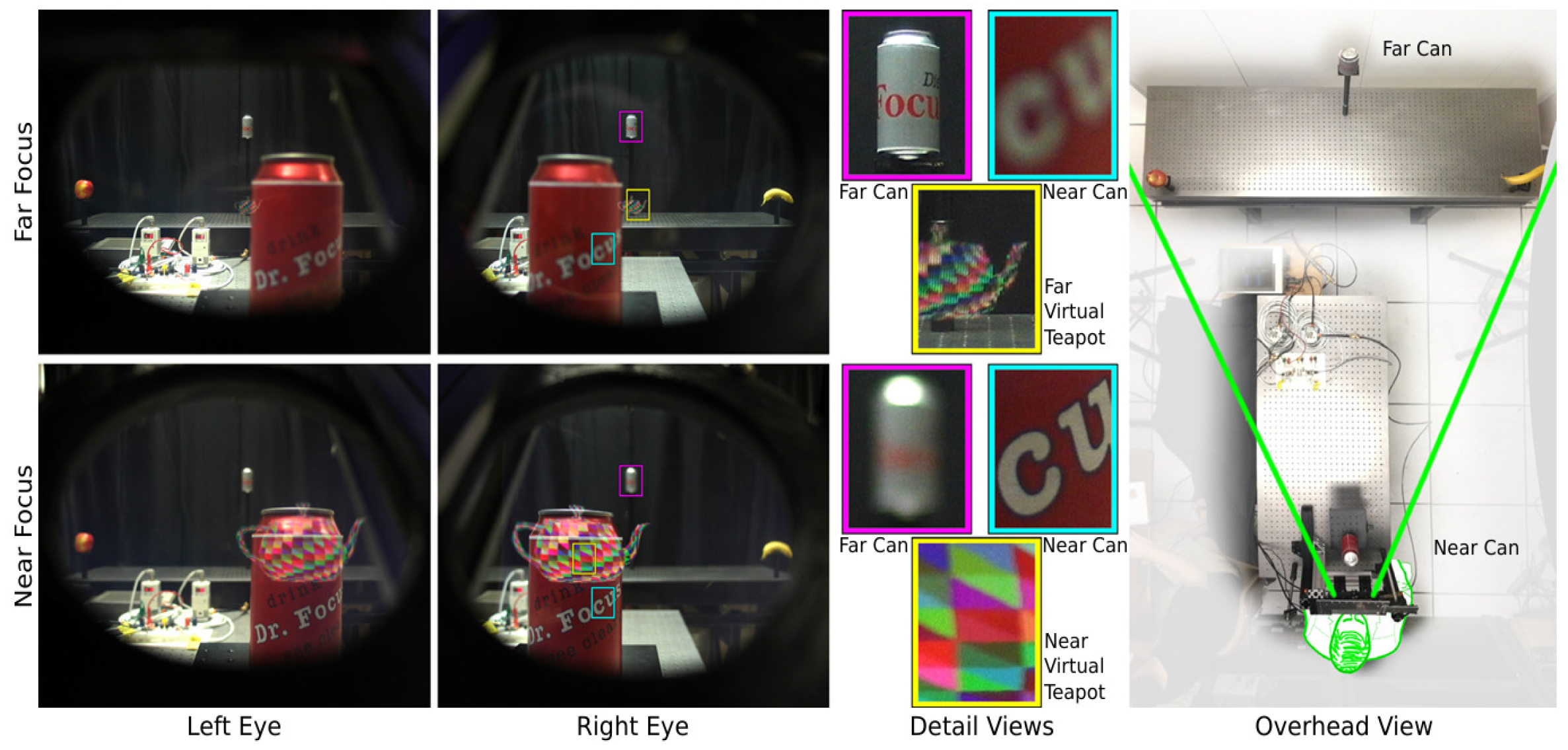
3.3. AR/VR
3.4. Laser Applications
3.5. Optical Communication
3.6. Adaptive Optical Zoom
4. Comparison
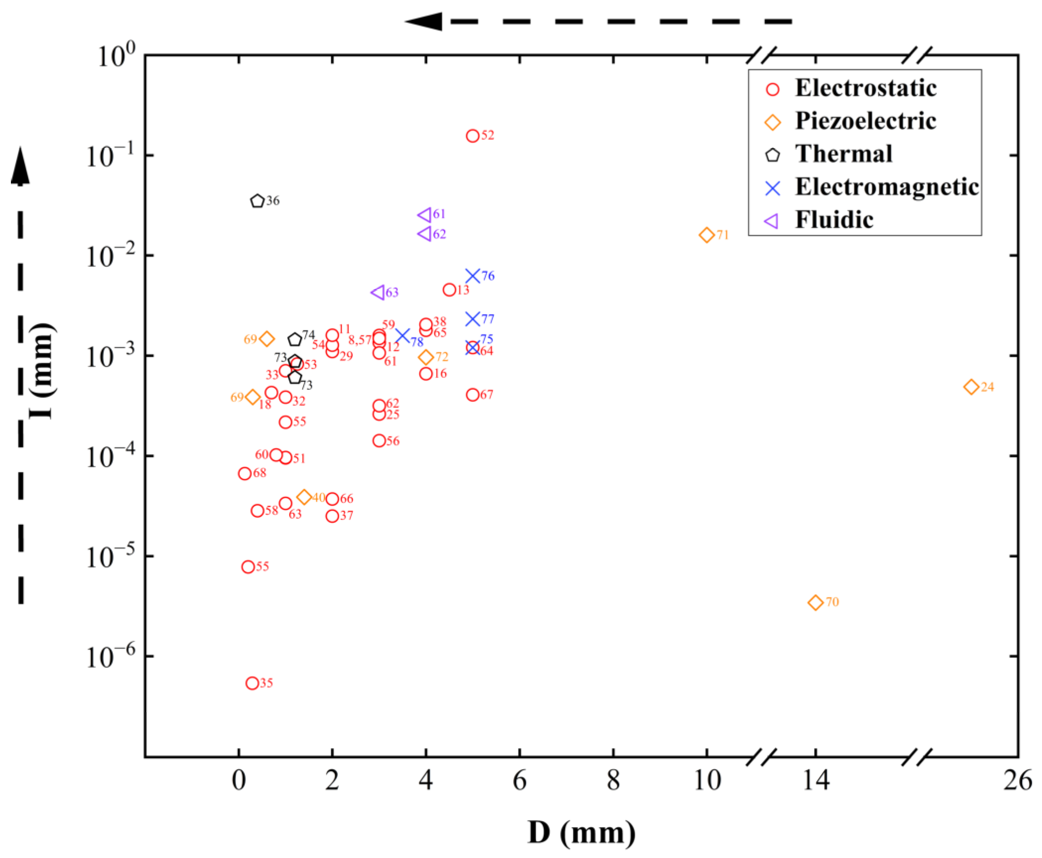
4.1. Comparison of Non-Resonant MEMS Reflective Varifocal Mirrors
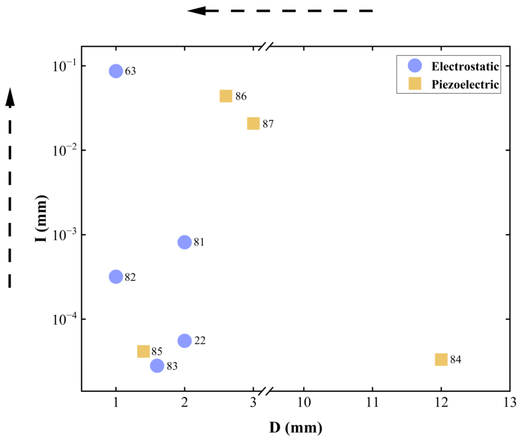
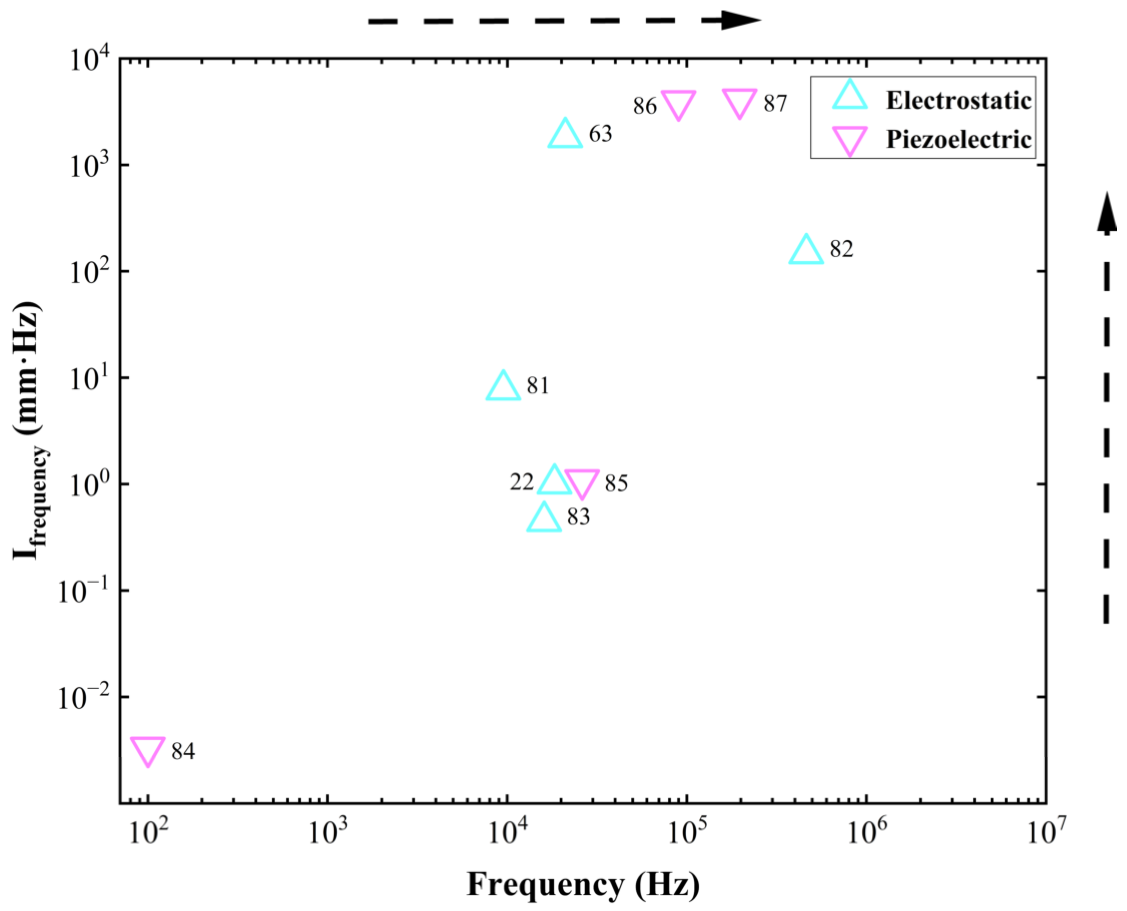
4.2. Comparison of Resonant MEMS Reflective Varifocal Mirrors
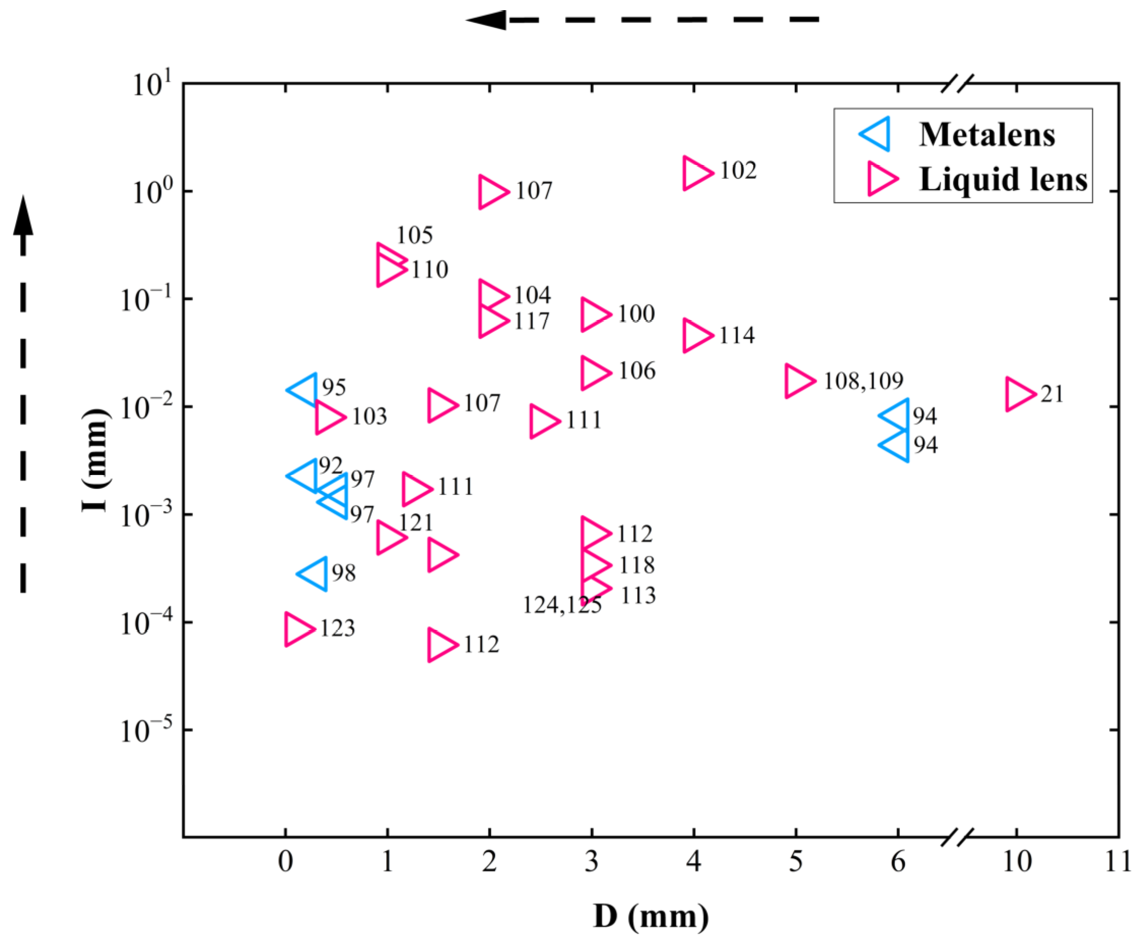
4.3. Comparison of MEMS Varifocal Microlenses
4.4. Overall Comparison
5. Conclusions and Outlook
Author Contributions
Funding
Acknowledgments
Conflicts of Interest
References
- Wick, D.V.; Martinez, T.; Payne, D.M.; Sweatt, W.C.; Restaino, S.R. Active optical zoom system. In Proceedings of the Defense and Security, Orlando, FL, USA, 28 March–1 April 2005. [Google Scholar]
- Kang, S.; Duocastella, M.; Arnold, C.B. Variable optical elements for fast focus control. Nat. Photonics 2020, 14, 533–542. [Google Scholar] [CrossRef]
- Žurauskas, M.; Barnstedt, O.; Frade-Rodriguez, M.; Waddell, S.; Booth, M.J. Rapid adaptive remote focusing microscope for sensing of volumetric neural activity. Biomed. Opt. Express 2017, 8, 4369–4379. [Google Scholar] [CrossRef]
- Pégard, N.C.; Liu, H.Y.; Antipa, N.; Gerlock, M.; Adesnik, H.; Waller, L. Compressive light-field microscopy for 3D neural activity recording. Optica 2016, 3, 517–524. [Google Scholar] [CrossRef]
- Masaaki, S.; Yuki, M.; Shogo, Y.; Keiko, G.A.; Masamichi, O.; Junichi, N. Fast varifocal two-photon micro endoscope for imaging neuronal activity in the deep brain. Biomed. Opt. Express 2017, 8, 4049–4060. [Google Scholar]
- Chen, T.H.; Fardel, R.; Arnold, C.B. Ultrafast z-scanning for high-efficiency laser micro-machining. Light Sci. Appl. 2018, 7, 17181. [Google Scholar] [CrossRef]
- Duocastella, M.; Arnold, C.B. Enhanced depth of field laser processing using an ultra-high-speed axial scanner. Appl. Phys. Lett. 2015, 102, 061113. [Google Scholar] [CrossRef]
- Moghimi, M.J.; Lutzenberger, B.J.; Kaylor, B.M.; Dickensheets, D.L. MOEMS deformable mirrors for focus control in vital microscopy. J. Micro/Nanolithogr. MEMS MOEMS 2011, 10, 023005. [Google Scholar] [CrossRef]
- Gad-el-Hak, M. MEMS: Introduction and Fundamentals, 1st ed.; CRC Press: Boca Raton, FL, USA, 2005; pp. 5–19. [Google Scholar]
- Liu, C. Foundations of MEMS, 2nd ed.; Pearson Education: Upper Saddle River, NJ, USA, 2012; pp. 1–27. [Google Scholar]
- Kaylor, B.M.; Wilson, C.R.; Greenfield, N.J.; Roos, P.A.; Seger, E.M.; Moghimi, M.J.; Dickensheets, D.L. Miniature non-mechanical zoom camera using deformable MOEMS mirrors. In Proceedings of the SPIE MOEMS-MEMS, San Francisco, CA, USA, 21–26 January 2012. [Google Scholar]
- Hsieh, H.T.; Wei, H.C.; Lin, M.H.; Hsu, W.Y.; Cheng, Y.C.; Su, G.D.J. Thin autofocus camera module by a large-stroke micromachined deformable mirror. Opt. Express 2010, 18, 11097–11104. [Google Scholar] [CrossRef]
- Wang, J.L.; Chen, T.Y.; Chien, Y.H.; Su, G.D.J. Miniature optical autofocus camera by micromachined fluoropolymer deformable mirror. Opt. Express 2009, 17, 6268–6274. [Google Scholar] [CrossRef]
- Ersumo, N.T.; Yalcin, C.; Antipa, N.; Pégard, N.; Waller, L.; Lopez, D.; Muller, R. Design framework for high-speed 3D scanning tools and development of an axial focusing micromirror-based array. In Proceedings of the SPIE OPTO, San Francisco, CA, USA, 1–6 February 2020. [Google Scholar]
- Dunn, D.; Tippets, C.; Torell, K.; Kellnhofer, P.; Akşit, K.; Didyk, P.; Myszkowski, K.; Luebke, D.; Fuchs, H. Wide field of view varifocal near-eye display using see-through deformable membrane mirrors. IEEE Trans. Vis. Comput. Graph. 2017, 23, 1322–1331. [Google Scholar] [CrossRef]
- Liu, T.; Svidunovich, A.J.; Wollant, B.C.; Dickensheets, D.L. MEMS 3-D scan mirror with SU-8 membrane and flexures for high NA microscopy. J. Microelectromech. Syst. 2018, 27, 719–729. [Google Scholar] [CrossRef] [PubMed]
- Liu, T.; Rajadhyaksha, M.; Dickensheets, D.L. MEMS-in-the-lens architecture for a miniature high-NA laser scanning microscope. Light Sci. Appl. 2019, 8, 59. [Google Scholar] [CrossRef]
- Moghimi, M.J.; Wilson, C.R.; Dickensheets, D.L. Improved micro-optoelectromechanical systems deformable mirror for in vivo optical microscopy. J. Micro/Nanolithogr. MEMS MOEMS 2012, 11, 043006. [Google Scholar] [CrossRef]
- Aljasem, K.; Werber, A.; Seifert, A.; Zappe, H. Fiber optic tunable probe for endoscopic optical coherence tomography. J. Opt. A Pure Appl. Opt. 2008, 10, 044012. [Google Scholar] [CrossRef]
- Geraldes, A.; Fiorini, P.; Mattos, L.S. An auto-focusing system for endoscopic laser surgery based on a hydraulic MEMS varifocal mirror. In Proceedings of the International Conference on Advanced Robotics (ICAR), Belo Horizonte, Brazil, 2–6 December 2019. [Google Scholar]
- Noda, K.; Binh-Khiem, N.; Takei, Y.; Takahata, T.; Matsumoto, K.; Shimoyama, I. Focal length measurement of a varifocal liquid lens with capacitance detection. Appl. Phys. B 2014, 115, 69–76. [Google Scholar] [CrossRef]
- Nakazawa, K.; Sasaki, T.; Furuta, H.; Kamiya, J.; Sasaki, H.; Kamiya, T.; Hane, K. Confocal laser displacement sensor using a micro-machined varifocal mirror. Appl. Opt. 2017, 56, 6911–6916. [Google Scholar] [CrossRef]
- Rabczuk, G.T.; Sawczak, M. Output characteristics of a high-power cw CO2 laser with a dynamic control of the optical cavity configuration. In Proceedings of the 2003 CHAPTER BOOKS, Bellingham, WA, USA, 31 December 2002–1 January 2003. [Google Scholar]
- Kopf, T.; Reinlein, C.; Goy, M.; Eberhardt, R.; Langebach, J.; Scheller, T. Adapting the axial focus in high-power laser processing machines within mm-range. In Proceedings of the SPIE LASE, San Francisco, CA, USA, 28 January–2 February 2017. [Google Scholar]
- Lukes, S.J.; Dickensheets, D.L. MEMS focus control and spherical aberration correction for multilayer optical discs. In Proceedings of the SPIE MOEMS-MEMS, San Francisco, CA, USA, 21–26 January 2012. [Google Scholar]
- Fujita, H.; Harada, M.; Sato, K. An Integrated Micro Servosystem. In Proceedings of the IEEE/RSJ International Conference on Intelligent Robots and Systems (IROS), Tokyo, Japan, 31 October–2 November 1988. [Google Scholar]
- Hisanaga, M.; Koumura, T.; Hattori, T. Fabrication of 3-dimensionally shaped Si diaphragm dynamic focusing mirror. In Proceedings of the IEEE International Conference on Micro Electro Mechanical Systems, Fort Lauderdale, FL, USA, 10 February 1993. [Google Scholar]
- Burns, D.M.; Bright, V.M. Micro-electro-mechanical focusing mirrors. In Proceedings of the IEEE International Conference on Micro Electro Mechanical Systems, Heidelberg, Germany, 25–29 January 1998. [Google Scholar]
- Himmer, P.A.; Dickensheets, D.L.; Friholm, R.A. Micromachined silicon nitride deformable mirrors for focus control. Opt. Lett. 2001, 26, 1280–1282. [Google Scholar] [CrossRef]
- Bifano, T. MEMS deformable mirrors. Nat. Photonics 2011, 5, 21–23. [Google Scholar] [CrossRef]
- Zeng, X.; Jiang, H. Liquid tunable microlenses based on MEMS techniques. Phys. D Appl. Phys. 2013, 46, 323001. [Google Scholar] [CrossRef]
- Qi, B.; Himmer, A.P.; Gordon, L.M.; Yang, X.V.; Dickensheets, D.L.; Vitkin, I.A. Dynamic focus control in high-speed optical coherence tomography based on a microelectromechanical mirror. Opt. Commun. 2004, 232, 123–128. [Google Scholar] [CrossRef]
- Yang, V.X.; Mao, Y.; Standish, B.A.; Munce, N.R.; Chiu, S.; Burnes, D.; Wilson, B.C.; Vitkin, I.A.; Himmer, P.A.; Dickensheets, D.L. Doppler optical coherence tomography with a micro-electro-mechanical membrane mirror for high-speed dynamic focus tracking. Opt. Lett. 2006, 31, 1262–1264. [Google Scholar] [CrossRef]
- Shao, Y.; Dickensheets, D.L.; Himmer, P. 3-D MOEMS mirror for laser beam pointing and focus control. IEEE J. Sel. Top. Quantum Electron. 2004, 10, 528–535. [Google Scholar] [CrossRef]
- Sasaki, T.; Hane, K. Varifocal micromirror integrated with comb-drive scanner on silicon-on-insulator wafer. J. Microelectromech. Syst. 2012, 21, 971–980. [Google Scholar] [CrossRef]
- Morrison, J.; Imboden, M.; Little, T.D.; Bishop, D.J. Electrothermally actuated tip-tilt-piston micromirror with integrated varifocal capability. Opt. Express 2015, 23, 9555–9566. [Google Scholar] [CrossRef] [PubMed]
- Nakazawa, K.; Sasaki, T.; Furuta, H.; Kamiya, J.; Kamiya, T.; Hane, K. Varifocal scanner using wafer bonding. J. Microelectromech. Syst. 2017, 26, 440–447. [Google Scholar] [CrossRef]
- Liu, T.; Dickensheets, D.L. 3-Dimensional beam scanner for a handheld confocal dermoscope. In Proceedings of the IEEE/LEOS International Conference on Optical MEMS, Singapore, 31 July–August 2016. [Google Scholar]
- Hamann, S.; Solgaard, O. Variable focusing and steering using high speed MEMS phased array. In Proceedings of the IEEE/LEOS International Conference on Optical MEMS, Lausanne, Switzerland, 29 July–2 August 2018. [Google Scholar]
- Sasaki, T.; Piot, A.; Fleury, C.; Guerreiro, S.; Rocha, R.T.; Lagosh, A. Two-Dimensional Piezoelectrically Actuated Micromirror with Fast Focusing Function. In Proceedings of the IEEE International Conference on Micro Electro Mechanical Systems, Austin, TX, USA, 21–25 January 2024. [Google Scholar]
- Pollock, C.; Morrison, J.; Imboden, M.; Little, T.D.; Bishop, D.J. Beam shaping with tip-tilt varifocal mirror for indoor optical wireless communication. Opt. Express 2017, 25, 20274–20285. [Google Scholar] [CrossRef]
- Bonora, S.; Poletto, L. Push-pull membrane mirrors for adaptive optics. Opt. Express 2006, 14, 11935–11944. [Google Scholar] [CrossRef]
- Verpoort, S.; Bittner, M.; Wittrock, U. Fast focus-shifter based on a unimorph deformable mirror. Appl. Opt. 2020, 59, 6959–6965. [Google Scholar] [CrossRef]
- Kasprzack, M.; Canuel, B.; Cavalier, F.; Day, R.; Genin, E.; Marque, J.; Sentenac, D.; Vajente, G. Performance of a thermally deformable mirror for correction of low-order aberrations in laser beams. Appl. Opt. 2013, 52, 2909–2916. [Google Scholar] [CrossRef]
- Ahmad, M.; Bahri, M.; Sawan, M. MEMS Micromirror Actuation Techniques: A Comprehensive Review of Trends, Innovations, and Future Prospects. Micromachines 2024, 15, 1233. [Google Scholar] [CrossRef]
- Allameh, M.; Park, B.; Shafai, C. Impact of Solid Materials in the Gap Space between Driving Electrodes in a MEMS Tri-Electrode Electrostatic Actuator. Sensors 2024, 24, 2743. [Google Scholar] [CrossRef] [PubMed]
- Eom, C.B.; Trolier-McKinstry, S. Thin-film piezoelectric MEMS. MRS Bull. 2012, 37, 1007–1017. [Google Scholar] [CrossRef]
- Latychevskaia, T. Lateral and axial resolution criteria in incoherent and coherent optics and holography, near-and far-field regimes. Appl. Opt. 2019, 58, 3597–3603. [Google Scholar] [CrossRef]
- Pribošek, J.; Bainschab, M.; Sasaki, T. Varifocal MEMS mirrors for high-speed axial focus scanning: A review. Microsyst. Nanoeng. 2023, 9, 135. [Google Scholar] [CrossRef] [PubMed]
- Song, Y.; Panas, R.M.; Hopkins, J.B. A review of micromirror arrays. Precis. Eng. 2018, 51, 729–761. [Google Scholar] [CrossRef]
- Himmer, P.A.; Dickensheets, D.L. Off-axis variable focus and aberration control mirrors. In Proceedings of the Micromachining and Microfabrication, San Jose, CA, USA, 25–31 January 2003. [Google Scholar]
- Mescheder, U.M.; Estañ, C.; Somogyi, G.; Freudenreich, M. Distortion optimized focusing mirror device with large aperture. Sens. Actuators A Phys. 2006, 130, 20–27. [Google Scholar] [CrossRef]
- Dickensheets, D.L.; Overcast, M.; Himmer, P.; Yang, V.X.; Vitkin, I.A. Focus tracking in time domain optical coherence tomography using membrane mirrors operated near snap-down. In Proceedings of the IEEE/LEOS International Conference on Optical MEMS, Big Sky, MT, USA, 21–24 August 2006; IEEE: New York, NY, USA, 2006; pp. 170–171. [Google Scholar]
- Lukes, S.; Lutzenberger, B.J.; Dunbar, E.; Shaw, S.R.; Dickensheets, D.L. Variable-focus SU-8 membrane mirror with enhanced stroke using feedback control. In Proceedings of the IEEE/LEOS International Conference on Optical MEMS, Clearwater, FL, USA, 17–20 August 2009. [Google Scholar]
- Hokari, R.; Hane, K. A varifocal convex micromirror driven by a bending moment. IEEE J. Sel. Top. Quantum Electron. 2009, 15, 1310–1316. [Google Scholar] [CrossRef]
- Kaylor, B.M.; Roos, P.A.; Lutzenberger, B.J.; Dahl, J.R.; Dickensheets, D.L. Novel MEMS deformable mirror for focus control and aberration correction. In Proceedings of the Imaging Systems and Applications, Tucson, AZ, USA, 7–8 June 2010. [Google Scholar]
- Lutzenburger, B.J.; Moghimi, M.J.; Lukes, S.J.; Kaylor, B.; Dickensheets, D.L. MEMS deformable mirrors for focus control in vital microscopy. In Proceedings of the SPIE MOEMS-MEMS, San Francisco, CA, USA, 23–28 January 2010. [Google Scholar]
- Sasaki, T.; Hane, K. Initial deflection of silicon-on-insulator thin membrane micro-mirror and fabrication of varifocal mirror. Sens. Actuators A Phys. 2011, 172, 516–522. [Google Scholar] [CrossRef]
- Lukes, S.J.; Dickensheets, D.L. SU-8 focus control mirrors released by XeF2 dry etch. In Proceedings of the SPIE MOEMS-MEMS, San Francisco, CA, USA, 22–27 January 2011. [Google Scholar]
- Strathman, M.; Liu, Y.; Li, X.; Lin, L.Y. Dynamic focus-tracking MEMS scanning micromirror with low actuation voltages for endoscopic imaging. Opt. Express 2013, 21, 23934–23941. [Google Scholar] [CrossRef]
- Moghimi, M.J.; Chattergoon, K.N.; Wilson, C.R.; Dickensheets, D.L. High speed focus control MEMS mirror with controlled air damping for vital microscopy. J. Microelectromech. Syst. 2013, 22, 938–948. [Google Scholar] [CrossRef]
- Lukes, S.J.; Dickensheets, D.L. SU-8 2002 surface micromachined deformable membrane mirrors. J. Microelectromech. Syst. 2013, 22, 94–106. [Google Scholar] [CrossRef]
- Sasaki, T.; Sato, D.; Hane, K. Displacement-amplified dynamic varifocal mirror using mechanical resonance. In Proceedings of the IEEE/LEOS International Conference on Optical MEMS, Kanazawa, Japan, 18–22 August 2013. [Google Scholar]
- Moghimi, M.J.; Wilson, C.; Dickensheets, D.L. Electrostatic-pneumatic membrane mirror with positive or negative variable optical power. In Proceedings of the SPIE MOEMS-MEMS, San Francisco, CA, USA, 2–7 February 2013. [Google Scholar]
- Lukes, S.J.; Downey, R.D.; Kreitinger, S.T.; Dickensheets, D.L. Four-zone varifocus mirrors with adaptive control of primary and higher-order spherical aberration. Appl. Opt. 2016, 55, 5208–5218. [Google Scholar] [CrossRef] [PubMed]
- Kallmann, U.; Lootze, M.; Mescheder, U. Simulative and experimental characterization of an adaptive astigmatic membrane mirror. Micromachines 2021, 12, 156. [Google Scholar] [CrossRef] [PubMed]
- Mescheder, U.; Lootze, M.; Aljasem, K. Evaluation and optimization of a moems active focusing device. Micromachines 2021, 12, 172. [Google Scholar] [CrossRef] [PubMed]
- Wang, W.; Ma, W. Varifocal-Piston Micromirror with Quasi-Simply Supported Piecewise Linear Flexure. IEEE J. Sel. Top. Quantum Electron. 2022, 28, 2800208. [Google Scholar] [CrossRef]
- Mescher, M.J.; Vladimer, M.L.; Bernstein, J.J. A novel high-speed piezoelectric deformable varifocal mirror for optical applications. In Proceedings of the IEEE International Conference on Micro Electro Mechanical Systems, Las Vegas, NV, USA, 24 January 2002. [Google Scholar]
- Stürmer, M.; Wapler, M.C.; Brunne, J.; Wallrabe, U. Focusing mirror with tunable eccentricity. In Proceedings of the IEEE/LEOS International Conference on Optical MEMS, Kanazawa, Japan, 18–22 August 2013. [Google Scholar]
- Wapler, M.C.; Lemke, F.; Alia, G.; Wallrabe, U. Aspherical high-speed varifocal mirror for miniature catadioptric objectives. Opt. Express 2018, 26, 6090–6102. [Google Scholar] [CrossRef]
- Inagaki, S.; Okamoto, Y.; Higo, A.; Mita, Y. High-resolution piezoelectric MEMS scanner fully integrated with focus-tuning and driving actuators. In Proceedings of the International Conference on Solid State Sensors and Actuators (TRANSDUCERS), Berlin, Germany, 23–27 June 2019. [Google Scholar]
- Li, L.; Li, R.; Lubeigt, W.; Uttamchandani, D. Design, simulation, and characterization of a bimorph varifocal micromirror and its application in an optical imaging system. J. Microelectromech. Syst. 2012, 22, 285–294. [Google Scholar] [CrossRef]
- Paterson, A.; Bauer, R.; Li, L.; Lubeigt, W.; Uttamchandani, D. Range extension of a bimorph varifocal micromirror through actuation by a peltier element. IEEE J. Sel. Top. Quantum Electron. 2014, 21, 72–78. [Google Scholar] [CrossRef]
- Hashizume, J.; Ide, T.; Kanamaru, M.; Mukoh, M.; Watanabe, K.; Yamauchi, Y. Non-contact deformable mirror actuator for spherical aberration compensation. Jpn. J. Appl. Phys. 2011, 50, 09MA02. [Google Scholar] [CrossRef]
- Hossain, M.M.; Bin, W.; Kong, S.H. Large-stroke convex micromirror actuated by electromagnetic force for optical power control. Opt. Express 2015, 23, 28358–28368. [Google Scholar] [CrossRef]
- Hossain, M.M.; Bin, W.; Kong, S.H. Electromagnetically controlled convex micromirror for focal length variation. In Proceedings of the IEEE SENSORS, Busan, Republic of Korea, 1–4 November 2015. [Google Scholar]
- Hossain, M.M.; Lee, J.Y.; Kong, S.H. Fabrication of a MEMS based symmetrically deformarle convex mirror. In Proceedings of the IEEE International Conference on Micro Electro Mechanical Systems, Las Vegas, NV, USA, 22–26 January 2017. [Google Scholar]
- Geraldes, A.; Fiorini, P.; Mattos, L.S. Design and fabrication of a hydraulic deformable membrane mirror for high-power laser focusing. In Proceedings of the IEEE/LEOS International Conference on Optical MEMS, Lausanne, Switzerland, 29 July–2 August 2018. [Google Scholar]
- Geraldes, A.; Jacassi, A.; Fiorini, P.; Mattos, L.S. Large-stroke varifocal mirror with hydraulic actuation for endoscopic laser surgery. In Proceedings of the IEEE/RAS-EMBS International Conference on Biomedical Robotics and Biomechatronics (BioRob), Enschede, The Netherlands, 26–29 August 2018. [Google Scholar]
- Nakazawa, K.; Sasaki, T.; Furuta, H.; Kamiya, J.; Sasaki, H.; Kamiya, T.; Hane, K. Resonant varifocal micromirror with piezoresistive focus sensor. Micromachines 2016, 7, 57. [Google Scholar] [CrossRef] [PubMed]
- Sasaki, T.; Kamada, T.; Hane, K. High-speed and large-amplitude resonant varifocal mirror. J. Robot. Mechatron. 2020, 32, 344–350. [Google Scholar] [CrossRef]
- Kocer, S.; Mukhangaliyeva, L.; Saritas, R.; Gulsaran, A.; Elhady, A.; Bell, K.; Kamei, A.; Basha, M.; Das, T.; Kayaharman, M.; et al. Resonant varifocal mems mirror. In Proceedings of the International Conference on Micro Electro Mechanical Systems, Tokyo, Japan, 9–13 January 2022. [Google Scholar]
- Tanaka, F.; Maeda, S.; Nagashima, K.; Tsuchiya, Y.; Tanaka, K.; Ishii, A.; Sugiyama, S. Mirror deformation by piezoelectric actuators. IEEJ Trans. Sens. Micromach. 2006, 126, 325–329. [Google Scholar] [CrossRef]
- Janin, P.; Bauer, R.; Griffin, P.; Riis, E.; Uttamchandani, D. Characterization of a fast piezoelectric varifocal MEMS mirror. In Proceedings of the IEEE/LEOS International Conference on Optical MEMS, Lausanne, Switzerland, 29 July–2 August 2018. [Google Scholar]
- Pribošek, J.; Bainschab, M.; Piot, A.; Moridi, M. Aspherical high-speed varifocal piezoelectric mems mirror. In Proceedings of the International Conference on Solid State Sensors and Actuators (TRANSDUCERS), Orlando, FL, USA, 20–24 June 2021. [Google Scholar]
- Pribošek, J.; Lagosh, A.; Thakkar, P.; Sasaki, T.; Bainschab, M. Resonant piezoelectric varifocal mirror with on-chip integrated diffractive optics for increased frequency response. In Proceedings of the IEEE International Conference on Micro Electro Mechanical Systems, Munich, Germany, 15–19 January 2023. [Google Scholar]
- Zhou, G.; Yu, H.; Chau, F.S. Microelectromechanically-driven miniature adaptive Alvarez lens. Opt. Express 2013, 21, 1226–1233. [Google Scholar] [CrossRef]
- Hoshino, K.; Shimoyama, I. An elastic thin-film microlens array with a pneumatic actuator. In Proceedings of the IEEE International Conference on Micro Electro Mechanical Systems, Interlaken, Switzerland, 25 January 2001. [Google Scholar]
- Merlo, S.; Crisà, E.; Ferrera, M.; Soldo, M. Experimental detection of piezo-tunable micro-lens performances by spot optical measurements. In Proceedings of the International Conference on Solid State Sensors and Actuators (TRANSDUCERS), Berlin, Germany, 23–27 June 2019. [Google Scholar]
- Chen, J.; Wang, W.; Fang, J.; Varahramyan, K. Variable-focusing microlens with microfluidic chip. J. Micromech. Microeng. 2004, 14, 675. [Google Scholar] [CrossRef]
- Kamali, S.M.; Arbabi, E.; Arbabi, A.; Horie, Y.; Faraon, A. Highly tunable elastic dielectric metasurface lenses. Laser Photonics Rev. 2016, 10, 1002–1008. [Google Scholar] [CrossRef]
- Arbabi, E.; Arbabi, A.; Kamali, S.M.; Horie, Y.; Faraji-Dana, M.; Faraon, A. MEMS-tunable dielectric metasurface lens. Nat. Commun. 2018, 9, 812. [Google Scholar] [CrossRef]
- She, A.; Zhang, S.; Shian, S.; Clarke, D.R.; Capasso, F. Adaptive metalenses with simultaneous electrical control of focal length, astigmatism, and shift. Sci. Adv. 2018, 4, eaap9957. [Google Scholar] [CrossRef]
- Han, Z.; Colburn, S.; Majumdar, A.; Böhringer, K.F. MEMS-actuated metasurface Alvarez lens. Microsyst. Nanoeng. 2020, 6, 79. [Google Scholar] [CrossRef]
- Han, Z.; Colburn, S.; Majumdar, A.; Böhringer, K.F. Millimeter-scale focal length tuning with MEMS-integrated meta-optics employing high-throughput fabrication. Sci. Rep. 2022, 12, 5385. [Google Scholar] [CrossRef]
- Han, Z.; Colburn, S.; Majumdar, A.; Böhringer, K.F. Mm-Scale Focal Length Tuning in Mems-Integrated Meta-Optics. In Proceedings of the IEEE International Conference on Micro Electro Mechanical Systems, Tokyo, Japan, 9–13 January 2022. [Google Scholar]
- Dirdal, C.A.; Thrane, P.C.; Dullo, F.T.; Gjessing, J.; Summanwar, A.; Tschudi, J. MEMS-tunable dielectric metasurface lens using thin-film PZT for large displacements at low voltages. Opt. Lett. 2022, 47, 1049–1052. [Google Scholar] [CrossRef] [PubMed]
- Dullo, F.; Jose, J.; Bouquet, G.; Skokic, Z.; Dirdal, C. Metasurface lens that is converging or diverging depending on transmission direction enables ultra-compact MEMS tunable reflective lens. arXiv 2024, arXiv:2402.02755. [Google Scholar]
- Krupenkin, T.; Yang, S.; Mach, P. Tunable liquid microlens. Appl. Phys. Lett. 2003, 82, 316–318. [Google Scholar] [CrossRef]
- Chronis, N.; Liu, G.L.; Jeong, K.H.; Lee, L.P. Tunable liquid-filled microlens array integrated with microfluidic network. Opt. Express 2003, 11, 2370–2378. [Google Scholar] [CrossRef] [PubMed]
- Agarwal, M.; Gunasekaran, R.A.; Coane, P.; Varahramyan, K. Polymer-based variable focal length microlens system. J. Micromech. Microeng. 2004, 14, 1665. [Google Scholar] [CrossRef]
- Werber, A.; Zappe, H. Tunable microfluidic microlenses. Appl. Opt. 2005, 44, 3238–3245. [Google Scholar] [CrossRef]
- Moran, P.M.; Dharmatilleke, S.; Khaw, A.H.; Tan, K.W.; Chan, M.L.; Rodriguez, I. Fluidic lenses with variable focal length. Appl. Phys. Lett. 2006, 88, 041120. [Google Scholar] [CrossRef]
- Nguyen, B.K.; Iwase, E.; Matsumoto, K.; Shimoyama, I. Electrically driven varifocal micro lens fabricated by depositing parylene directly on liquid. In Proceedings of the IEEE International Conference on Micro Electro Mechanical Systems, Hyogo, Japan, 21–25 January 2007. [Google Scholar]
- Cheng, C.C.; Andrew, Y.J. Dielectrically actuated liquid lens. Opt. Express 2007, 15, 7140–7145. [Google Scholar] [CrossRef]
- Aljasem, K.; Werber, A.; Reichelt, S.; Mader, D.; Zappe, H. Pneumatically-actuated tunable microlens for endoscopic optical coherence tomography. In Proceedings of the International Conference on Solid State Sensors and Actuators (TRANSDUCERS), Lyon, France, 10–14 June 2007. [Google Scholar]
- Schneider, F.; Müller, C.; Wallrabe, U. A low cost adaptive silicone membrane lens. J. Opt. A Pure Appl. Opt. 2008, 10, 044002. [Google Scholar] [CrossRef]
- Schneider, F.; Eberhard, D.; Strohmeier, D.; Muller, C.; Wallrabe, U. Adaptive fluidic PDMS-lens with integrated piezoelectric actuator. In Proceedings of the IEEE International Conference on Micro Electro Mechanical Systems, Tucson, AZ, USA, 13–17 January 2008. [Google Scholar]
- Binh-Khiem, N.; Matsumoto, K.; Shimoyama, I. Polymer thin film deposited on liquid for varifocal encapsulated liquid lenses. Appl. Phys. Lett. 2008, 93, 124101. [Google Scholar] [CrossRef]
- Yu, H.B.; Zhou, G.Y.; Chau, F.K.; Lee, F.W.; Wang, S.H.; Leung, H.M. A liquid-filled tunable double-focus microlens. Opt. Express 2009, 17, 4782–4790. [Google Scholar] [CrossRef]
- Pouydebasque, A.; Bolis, S.; Bridoux, C.; Jacquet, F.; Moreau, S.; Sage, E.; Saint-Patrice, D.; Bouvier, C.; Kopp, C.; Sillon, N.; et al. Process optimization and performance analysis of an electrostatically actuated varifocal liquid lens. In Proceedings of the International Conference on Solid State Sensors and Actuators (TRANSDUCERS), Beijing, China, 5–9 June 2011. [Google Scholar]
- Pouydebasque, A.; Bridoux, C.; Jacquet, F.; Moreau, S.; Sage, E.; Saint-Patrice, D.; Kopp, C.; Marchand, G.; Bolis, S.; Sillon, N.; et al. Varifocal liquid lenses with integrated actuator, high focusing power and low operating voltage fabricated on 200 mm wafers. Sens. Actuators A Phys. 2011, 172, 280–286. [Google Scholar] [CrossRef]
- Li, C.; Jiang, H. Electrowetting-driven variable-focus microlens on flexible surfaces. Appl. Phys. Lett. 2012, 100, 231105. [Google Scholar] [CrossRef]
- Ashtiani, A.O.; Jiang, H. Thermally actuated liquid tunable microlens with embedded thermoelectric driver and sub-second response time. In Proceedings of the International Conference on Solid State Sensors and Actuators (TRANSDUCERS), Barcelona, Spain, 16–20 June 2013. [Google Scholar]
- Seo, S.; Park, Y.; Lee, J.H. Lateral positioning of tunable liquid microlens with four coplanar electrodes. In Proceedings of the IEEE/LEOS International Conference on Optical MEMS, Glasgow, UK, 17–21 August 2014. [Google Scholar]
- Zhang, W.; Zappe, H.; Seifert, A. Wafer-scale fabricated thermo-pneumatically tunable microlenses. Light Sci. Appl. 2014, 3, e145. [Google Scholar] [CrossRef]
- Nicolas, S.; Allain, M.; Bridoux, C.; Fanget, S.; Lesecq, S.; Zarudniev, M.; Bolis, S.; Pouydebasque, A.; Jacquet, F. Fabrication and characterization of a new varifocal liquid lens with embedded PZT actuators for high optical performances. In Proceedings of the IEEE International Conference on Micro Electro Mechanical Systems, Estoril, Portugal, 18–22 January 2015. [Google Scholar]
- Ashtiani, A.O.; Jiang, H. Design and fabrication of an electrohydrodynamically actuated microlens with areal density modulated electrodes. J. Micromech. Microeng. 2015, 26, 015004. [Google Scholar] [CrossRef]
- Ashtiani, A.O.; Jiang, H. An electrohydrodynamically actuated liquid microlens with areal density modulated electrodes. In Proceedings of the International Conference on Solid State Sensors and Actuators (TRANSDUCERS), Anchorage, AK, USA, 21–25 June 2015. [Google Scholar]
- Almoallem, Y.D.; Jiang, H. Tunable dielectrophoretic microlens with lowered driving voltage. In Proceedings of the International Conference on Solid State Sensors and Actuators (TRANSDUCERS), Kaohsiung, Taiwan, 18–22 June 2017. [Google Scholar]
- Seo, S.; Yoo, S.K.; Kim, J.A.; Moon, D. Liquid microlens enabling tunable focus and tilt for resolution enhancement of 3d image. In Proceedings of the International Conference on Solid State Sensors and Actuators (TRANSDUCERS), Berlin, Germany, 23–27 June 2019. [Google Scholar]
- Xu, M.; Liu, Y.; Li, S.; Li, J.; Zhang, L.; Lu, H. Vari-focal liquid microlens array using an electrically responsive fluid actuated by a ring array patterned electrode. Appl. Opt. 2022, 61, 9781–9787. [Google Scholar] [CrossRef]
- Tang, Z.; Soda, L.; Okatani, T.; Vergara, A.; Suzuki, Y.; Tanaka, S. PZT Mems Tunable Liquid Lens with Integrated Piezoresistive Position Sensor. In Proceedings of the International Conference on Solid State Sensors and Actuators (TRANSDUCERS), Kyoto, Japan, 25–29 June 2023. [Google Scholar]
- Tang, Z.; Vergara, A.; Okatani, T.; Suzuki, Y.; Tanaka, S. Investigation on liquid medium integration for piezoelectric MEMS tunable liquid lenses. Sens. Actuators A Phys. 2024, 377, 115732. [Google Scholar] [CrossRef]
- He, S.; Yang, H.; Jiang, Y.; Deng, W.; Zhu, W. Recent Advances in MEMS Metasurfaces and Their Applications on Tunable Lens. Micromachines 2019, 10, 505. [Google Scholar] [CrossRef]
- Hamann, S.; Ceballos, A.; Landry, J.; Solgaard, O. High-speed random access optical scanning using a linear MEMS phased array. Opt. Lett. 2018, 43, 5455–5458. [Google Scholar] [CrossRef]
- Landry, J.R.; Hamann, S.S.; Solgaard, O. Random access cylindrical lensing and beam steering using a high-speed linear phased array. IEEE Photonics Technol. Lett. 2020, 32, 859–862. [Google Scholar] [CrossRef]
- Ersumo, N.T.; Yalcin, C.; Antipa, N.; Pégard, N.; Waller, L.; Lopez, D.; Muller, R. A micromirror array with annular partitioning for high-speed random-access axial focusing. Light Sci. Appl. 2020, 9, 183. [Google Scholar] [CrossRef] [PubMed]
- MEMS Drive Inc. MEMS Drive. Available online: http://memsdrive.com/ (accessed on 4 April 2025).
- Polight. Available online: https://www.polight.com/home/default.aspx (accessed on 4 April 2025).
- Elliott, A.D. Confocal microscopy: Principles and modern practices. Curr. Protoc. Cytom. 2020, 92, e68. [Google Scholar] [CrossRef] [PubMed]
- Bouma, B.E.; de Boer, J.F.; Huang, D.; Jang, I.K.; Yonetsu, T.; Leggett, C.L.; Leitgeb, R.; Sampson, D.D.; Suter, M.; Vakoc, B.J.; et al. Optical coherence tomography. Nat. Rev. Methods Primers 2022, 2, 79. [Google Scholar] [CrossRef] [PubMed]
- Jiang, J.; Zhou, G.; Duffy, B.M.; Duffy, V.G. AR and VR–A Review on Recent Progress and Applications. In Proceedings of the International Conference on Human-Computer InteractiMEMS Reflective Varifocal Mirrorson, Washington, DC, USA, 29 June–4 July 2023. [Google Scholar]
- Hoffman, D.M.; Girshick, A.R.; Akeley, K.; Banks, M.S. Vergence–accommodation conflicts hinder visual performance and cause visual fatigue. J. Vis. 2008, 8, 33. [Google Scholar] [CrossRef]
- Wick, D.V.; Martinez, T. Adaptive optical zoom. Opt. Eng. 2004, 3, 8–9. [Google Scholar]


| Type | Year | Author | Deformation | Mirror Size | Focal Length Variation | I (×10−6) |
|---|---|---|---|---|---|---|
| Electrostatic | 2001 | Himmer et al. [29] | concave | 1 mm × 1 mm | 36 mm–360 mm | 95.49 mm |
| 2003 | Himmer et al. [51] | concave | 1.4 mm × 1 mm * | 36 mm–inf | 96.45 mm | |
| 2004 | Qi et al. [32] | concave | 1.4 mm × 1 mm * | 18 mm–inf | 385.8 mm | |
| 2004 | Shao et al. [34] | concave | 0.7 mm × 0.7 mm | 10 mm–inf | 428.75 mm | |
| 2006 | Mescheder et al. [52] | concave | 5 mm × 5 mm | 10 mm–inf | 156,250 mm | |
| 2006 | Dickensheets et al. [53] | concave | 1.25 mm × 1.25mm | 17.2 mm–inf | 825.25 mm | |
| 2006 | Yang et al. [33] | concave | 1.4 mm × 1 mm * | 13.3 mm–inf | 706.65 mm | |
| 2009 | Lukes et al. [54] | concave | 2 mm × 2 mm | 30.1 mm–inf | 1103.74 mm | |
| 2009 | Hokari et al. [55] | convex | 1 mm × 1 mm | −24 mm–inf | 217.01 mm | |
| 0.4 mm × 1 mm # | −32 mm–−710 mm | 7.80 mm | ||||
| 2009 | Wang et al. [13] | concave | 4.5 mm × 4.5 mm | 50 mm–inf | 4556.25 mm | |
| 2010 | Hsieh et al. [12] | concave | 3 mm × 3 mm | 50 mm–inf | 1350 mm | |
| 2010 | Kaylor et al. [56] | concave | 3 mm × 3 mm | 154 mm–inf | 142.31 mm | |
| 2010 | Lutzenburger et al. [57] | concave | 3 mm × 3 mm | 47 mm–inf | 1527.84 mm | |
| 2011 | Moghimi et al. [8] | concave | 3 mm × 3 mm | 47 mm–inf | 1527.84 mm | |
| 2011 | Sasaki et al. [58] | concave convex | 0.4 mm × 0.4 mm | −28 mm–inf 21 mm–inf | 28.34 mm | |
| 2011 | Lukes et al. [59] | concave | 3 mm × 4.24 mm * | 47.6 mm–inf | 1489.57 mm | |
| 2012 | Lukes et al. [25] | concave | 3 mm × 4.24 mm * | 113.6 mm–inf | 261.53 mm | |
| 2012 | Moghimi et al. [18] | concave | 2 mm × 2mm | 28 mm–inf | 1275.51 mm | |
| 2012 | Sasaki et al. [35] | concave convex | 0.29 mm × 0.29 mm | −128 mm–inf 93 mm–inf | 0.54 mm | |
| 2012 | Kaylor et al. [11] | concave | 2 mm × 2 mm | 25 mm–inf | 1600 mm | |
| 2013 | Strathman [60] | concave | 0.8 mm × 0.8 mm | 25 mm–inf | 102.4 mm | |
| 2013 | Moghimi et al. [61] | concave | 3 mm × 3 mm | 56.25 mm–inf | 1066.67 mm | |
| 2013 | Lukes et al. [62] | concave | 3 mm × 4.24 mm * | 103.2 mm–inf | 316.89 mm | |
| 3 mm × 4.24 mm * | – | – | ||||
| 2013 | Sasaki et al. [63] | concave | 1 mm × 1 mm | 59.5 mm–271.7 mm | 33.61 mm | |
| 2014 | Moghimi et al. [64] | concave convex | 5 mm × 5 mm | −208.3 mm–inf 135.9 mm–inf | 1206.14 mm | |
| 2016 | Lukes et al. [65] | concave | 4 mm × 4 mm | 66.7 mm–inf | 1798.2 mm | |
| 2016 | Liu et al. [38] | concave | 4 mm × 4 mm | 62.5 mm–inf | 2048 mm | |
| 2017 | Nakazawa et al. [37] | concave convex | 2 mm × 2 mm | −523 mm–inf 216 mm–inf | 25.09 mm | |
| 2018 | Liu et al. [16] | concave | 4 mm × 4 mm | 110 mm–inf | 661.16 mm | |
| 2021 | Kallmann et al. [66] | concave | 8 mm × 2 mm | 163.9 mm–3333.3 mm | 37.14 mm | |
| 2021 | Mescheder et al. [67] | concave | 5 mm × 5 mm | 196 mm–inf | 406.73 mm | |
| 2022 | Wang et al. [68] | concave | 0.13 mm × 0.13 mm | 2.03 mm–79.8 mm | 66.6 mm | |
| Piezoelectric | 2002 | Mescher et al. [69] | concave | 0.6 mm × 0.6 mm | 1.62 mm–1.75 mm | 1471.74 mm |
| 0.3 mm × 0.3 mm | 1.78 mm–2.23 mm | 386.53 mm | ||||
| 2013 | Stürmer et al. [70] | concave | 14 mm × 14 mm | 10,000 mm–inf | 3.43 mm | |
| 2017 | Kopf et al. [24] | convex | 25 mm × 25 mm | −2000 mm–inf | 488.28 mm | |
| 2018 | Wapler et al. [71] | concave convex | 10 mm × 10 mm | −125 mm–inf 125 mm–inf | 16,000 mm | |
| 2019 | Inagaki et al. [72] | concave convex | 4 mm × 4 mm | −120 mm–inf 140 mm–inf | 963.72 mm | |
| 2024 | Sasaki et al. [40] | concave | 1.4 mm × 1.4 mm | 85 mm–200 mm | 38.90 mm | |
| Thermal | 2012 | Li et al. [73] | concave | 1.2 mm × 1.2 mm | 11.5 mm–16.9 mm | 876.99 mm |
| 11.5 mm–14.5 mm | 605.92 mm | |||||
| 2014 | Paterson et al. [74] | concave | 1.2 mm × 1.2 mm | 9.6 mm–15.5 mm | 1444.69 mm | |
| 2015 | Morrison et al. [36] | concave convex | 0.4 mm × 0.4 mm | −0.48 mm–inf 20.5 mm–inf | 34,741.26 mm | |
| Electromagnetic | 2011 | Hashizume et al. [75] | concave | 5 mm × 5 mm | 111.6 mm–558 mm | 1204.4 mm |
| 2015 | Hossain et al. [76] | convex | 5 mm × 5 mm | −50 mm–inf | 6250 mm | |
| 2015 | Hossain et al. [77] | convex | 5 mm × 5 mm | −82 mm–−4938 mm | 2323.12 mm | |
| 2017 | Hossain et al. [78] | convex | 3.5 mm × 3.5 mm | −58.1 mm–inf | 1587.68 mm | |
| Fluidic | 2018 | Geraldes et al. [79] | concave convex | 4 mm × 4 mm | 24.61 mm–inf −25.72 mm–inf | 25,302.29 mm |
| 2018 | Geraldes et al. [80] | concave convex | 4 mm × 4 mm | 32.15 mm–inf −30.26 mm–inf | 16,476.56 mm | |
| 2019 | Geraldes et al. [20] | concave convex | 3 mm × 4.24 mm | −38.3 mm–inf 41.5 mm–inf | 4260.43 mm |
| Year | Author | Type | Deformation | Mirror Size | Focal Length Variation | Frequency | Iresonance |
|---|---|---|---|---|---|---|---|
| 2013 | Sasaki et al. [63] | Electrostatic | concave | 1 mm × 1 mm | 1.2 mm–271.7mm | 21 kHz | 1822.88 |
| 2016 | Nakazawa et al. [81] | Electrostatic | concave convex | 2mm × 2 mm | 35 mm–inf −41 mm–inf | 9.5 kHz | 7.76 |
| 2017 | Nakazawa et al. [22] | Electrostatic | concave convex | 2 mm × 2 mm | 139 mm–inf −523 mm–inf | 18.3 kHz | 1.01 |
| 2020 | Sasaki et al. [82] | Electrostatic | concave convex | 1 mm × 1 mm | 28 mm–inf −28 mm–inf | 462.7 kHz | 147.54 |
| 2022 | Kocer et al. [83] | Electrostatic | concave | 1.6 mm × 1.6 mm | 110 mm–190 mm | 16 kHz | 0.45 |
| 2006 | Tanaka et al. [84] | Piezoelectric | convex | 12 mm × 12 mm | 900 mm–inf | 0.1 kHz | 0.003 |
| 2018 | Janin et al. [85] | Piezoelectric | concave convex | 1.4 mm × 1.4 mm | 96.2 mm–inf −278 mm–inf | 26.1 kHz | 1.08 |
| – | 107 kHz | – | |||||
| 2021 | Pribošek et al. [86] | Piezoelectric | concave convex | 2.6 mm × 2.6 mm | −10 mm–inf 10 mm–inf | 90 kHz | 3954.6 |
| 2023 | Pribošek et al. [87] | Piezoelectric | concave convex | 3 mm × 3 mm | 18 mm–inf −18 mm–inf | 197 kHz | 4104.2 |
| Year | Author | Size | Focal Length Variation | I (×10−6) |
|---|---|---|---|---|
| 2016 | Kamali et al. [92] | 0.2 mm × 0.2 mm # | 0.6 mm–1.4 mm | 2267.57 mm |
| 2018 | Arbabi et al. [93] | – | 0.627 mm–0.824 mm | – |
| 2018 | She et al. [94] | 6 mm × 6 mm | 50 mm–65 mm | 4409.47 mm |
| 50 mm–103.5 mm | 8279.52 mm | |||
| 2020 | Han et al. [95] | 0.2 mm × 0.2 mm # | 0.182 mm–0.25 mm | 14,189.59 mm |
| 2022 | Han et al. [96] | 0.5 mm × 0.5 mm # | – | – |
| 2022 | Han et al. [97] | 0.5 mm × 0.5 mm # | 2.7 mm–5.8 mm | 1678.87 mm |
| 0.5 mm × 0.5 mm # | 3 mm–6 mm | 1302.08 mm | ||
| 2022 | Dirdal et al. [98] | 0.3 mm × 0.3 mm | 1.7 mm–1.95 mm | 280.25 mm |
| 2024 | Dullo et al. [99] | 1.5 mm × 1.5 mm | – | – |
| Year | Author | Size | Focal Length Variation | I (×10−6) |
|---|---|---|---|---|
| 2003 | Krupenkin et al. [100] | 3 mm × 3 mm | 3.8 mm–4.56 mm | 71,416.2 mm |
| 2003 | Chronis et al. [101] | – | 1.8 mm–6 mm (Norland 63) | – |
| 0.6 mm–2 mm (Oil) | – | |||
| 2004 | Agarwal et al. [102] | 4 mm × 4 mm | −75.9 mm–−3.3 mm 3.1 mm–75.9 mm | 1,466,460.45 mm |
| 2005 | Werber et al. [103] | 0.4 mm × 0.4 mm | 1 mm–18 mm | 7975.31 mm |
| 2006 | Moran et al. [104] | 2 mm × 2 mm | 2.86 mm–7.69 mm | 105,345.22 mm |
| 2007 | Nguyen et al. [105] | 1 mm × 1 mm | 0.8 mm–3.8 mm | 186,655.99 mm |
| 2007 | Cheng et al. [106] | 3 mm × 3 mm | 12 mm–34 mm | 20,517.95 mm |
| 2007 | Aljasem et al. [107] | 1.5 mm × 1.5 mm | 5 mm–8 mm | 10,283.2 mm |
| 2 mm × 2 mm | 1 mm–7 mm | 979,591.84 mm | ||
| 2008 | Schneider et al. [108,109] | 5 mm × 5 mm | 30 mm–500 mm | 17,298.61 mm |
| 2008 | Binh-Khiem et al. [110] | 1 mm × 1 mm | 0.8 mm–3.7 mm | 186,181.75 mm |
| 2009 | Yu et al. [111] | 1.25 mm × 1.25 mm | 11.95 mm–inf | 1709.64 mm |
| 2.5 mm × 2.5 mm | 16.35 mm–inf | 7306.25 mm | ||
| 2011 | Pouydebasque et al. [112] | 1.5 mm × 1.5 mm | −200 mm–inf 90.9 mm–inf | 61.6 mm |
| 3 mm × 3 mm | −1000 mm–inf 71.4 mm–inf | 665.4 mm | ||
| 2011 | Pouydebasque et al. [113] | 3 mm × 3 mm | −200 mm–inf 166.7 mm–inf | 205.83 mm |
| 2012 | Li et al. [114] | 4 mm × 4 mm | −15 mm–inf 28 mm–inf | 45,759.64 mm |
| 2013 | Ashtiani et al. [115] | – | −22.6 mm–inf 22.6 mm–inf | – |
| 2014 | Seo et al. [116] | – | 9.3 mm–29.7 mm | – |
| 2014 | Zhang et al. [117] | 2 mm × 2 mm | 4 mm–inf | 62,500 mm |
| 2014 | Noda et al. [21] | 10 mm × 10 mm | 82.6 mm–153.6 mm | 13,022.84 mm |
| 2015 | Nicolas et al. [118] | 3 mm × 3 mm | 100 mm–inf | 337.5 mm |
| 2015 | Ashtiani et al. [119] | – | 5.8 mm–10.1 mm | – |
| 2015 | Ashtiani et al. [120] | – | 6.4 mm–33.7 mm | – |
| 2017 | Almoallem et al. [121] | 1 mm × 1 mm | 14 mm–67 mm | 609.91 mm |
| 2019 | Seo et al. [122] | – | 9.3 mm–29.3 mm | – |
| 2022 | Xu et al. [123] | 0.1 mm × 0.1 mm | 0.92 mm–1.42 mm | 85.69 mm |
| 2024 | Tang et al. [124,125] | 1.5 mm × 1.5 mm | 31.6 mm–inf | 422.48 mm |
| Type | Electrostatic | Piezoelectric | Thermal | Electromagnetic | Fluidic | |
|---|---|---|---|---|---|---|
| Characteristics | ||||||
| Stroke | limited | large | large | large | large | |
| Varifocal speed | medium | fast | slow | slow | slow | |
| Energy consumption | low | low | high | high | — | |
| Structure | simple | medium | complex | complex | simple | |
| Type | Basic Principle | Achievable Optical Power Variation Maximum | Achievable Varifocal Speed Maximum | Practical Applications | |
|---|---|---|---|---|---|
| MEMS reflective varifocal mirrors | Parabolic deformation of reflective surface | 100 D | 460 kHz | Confocal; OCT; AR/VR; Zoom camera; 3D scanning; Laser process; Head-write heads | |
| MEMS varifocal microlenses | Metalenses | Modulation of optical phase with subwavelength microstructures | 10 D | 2 kHz | Confocal; OCT; Zoom cameras |
| Liquid lenses | Deformation of a liquid droplet | 100 D | 0.3 kHz | ||
| MEMS phased varifocal mirrors | Modulation of optical phase | — | 15 kHz | 3D scanning | |
Disclaimer/Publisher’s Note: The statements, opinions and data contained in all publications are solely those of the individual author(s) and contributor(s) and not of MDPI and/or the editor(s). MDPI and/or the editor(s) disclaim responsibility for any injury to people or property resulting from any ideas, methods, instructions or products referred to in the content. |
© 2025 by the authors. Licensee MDPI, Basel, Switzerland. This article is an open access article distributed under the terms and conditions of the Creative Commons Attribution (CC BY) license (https://creativecommons.org/licenses/by/4.0/).
Share and Cite
Liu, C.; Wang, T.; Wang, X.; Chang, M.; Jian, Y.; Wang, W. MEMS Varifocal Optical Elements for Focus Control. Micromachines 2025, 16, 482. https://doi.org/10.3390/mi16040482
Liu C, Wang T, Wang X, Chang M, Jian Y, Wang W. MEMS Varifocal Optical Elements for Focus Control. Micromachines. 2025; 16(4):482. https://doi.org/10.3390/mi16040482
Chicago/Turabian StyleLiu, Chen, Tong Wang, Xin Wang, Manpeng Chang, Yu Jian, and Weimin Wang. 2025. "MEMS Varifocal Optical Elements for Focus Control" Micromachines 16, no. 4: 482. https://doi.org/10.3390/mi16040482
APA StyleLiu, C., Wang, T., Wang, X., Chang, M., Jian, Y., & Wang, W. (2025). MEMS Varifocal Optical Elements for Focus Control. Micromachines, 16(4), 482. https://doi.org/10.3390/mi16040482