Container-Sized CO2 to Methane: Design, Construction and Catalytic Tests Using Raw Biogas to Biomethane

 ,
,
Abstract
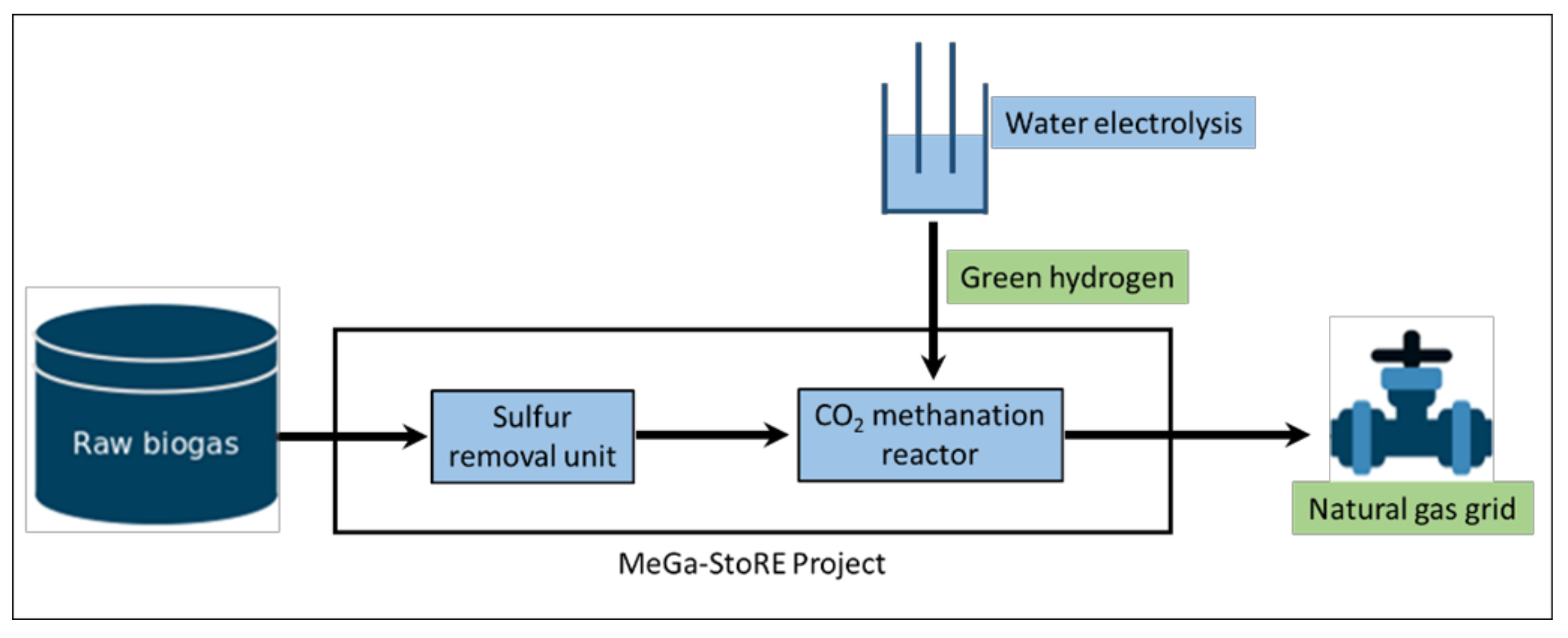
:1. Introduction
2. Results and Discussion
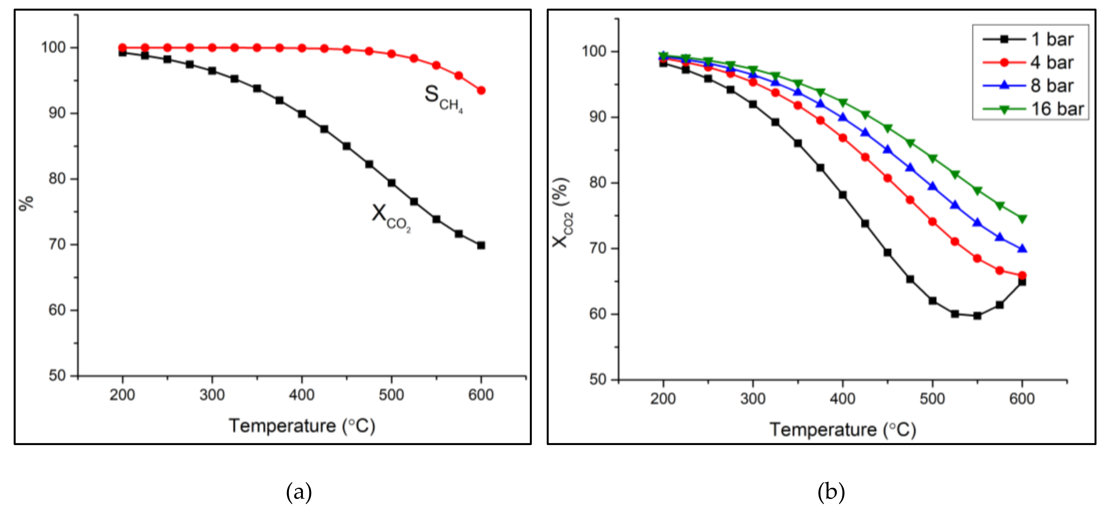
2.1. Thermodynamic Calculations
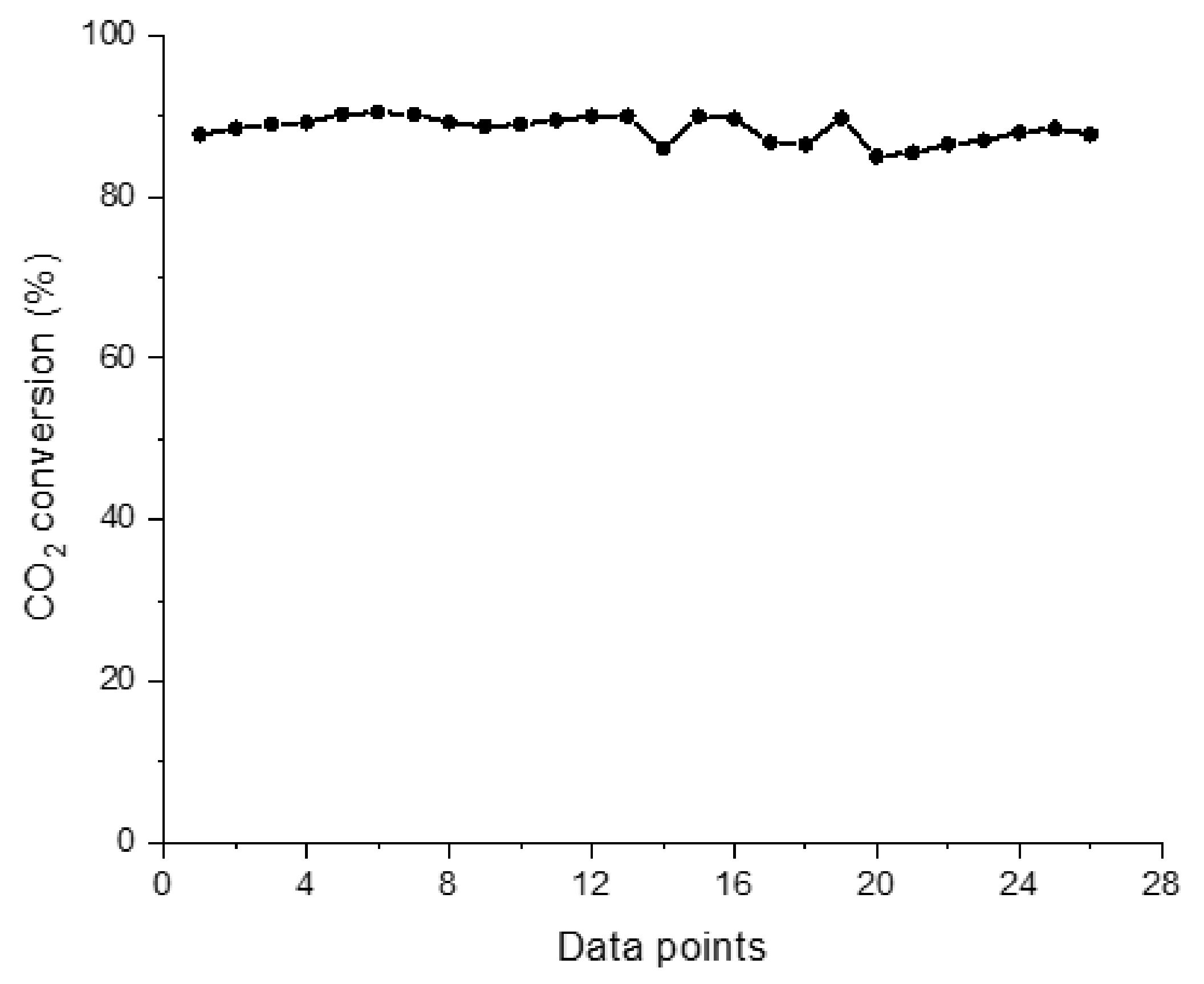
2.2. Experimental Results
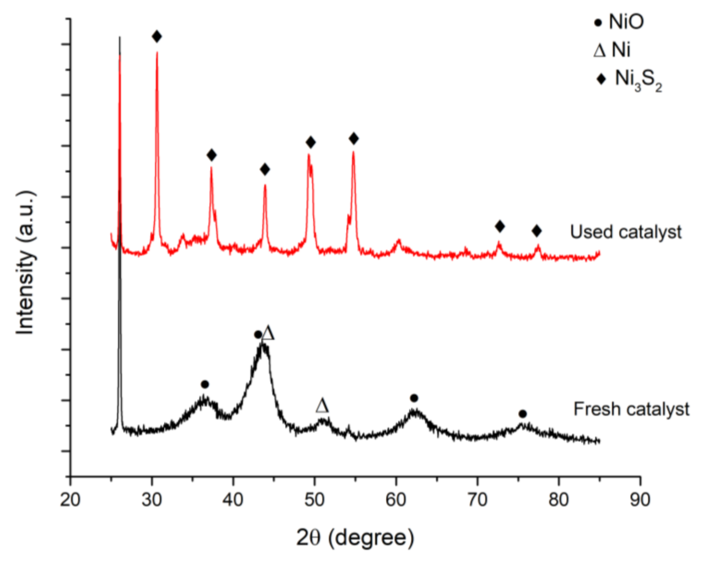
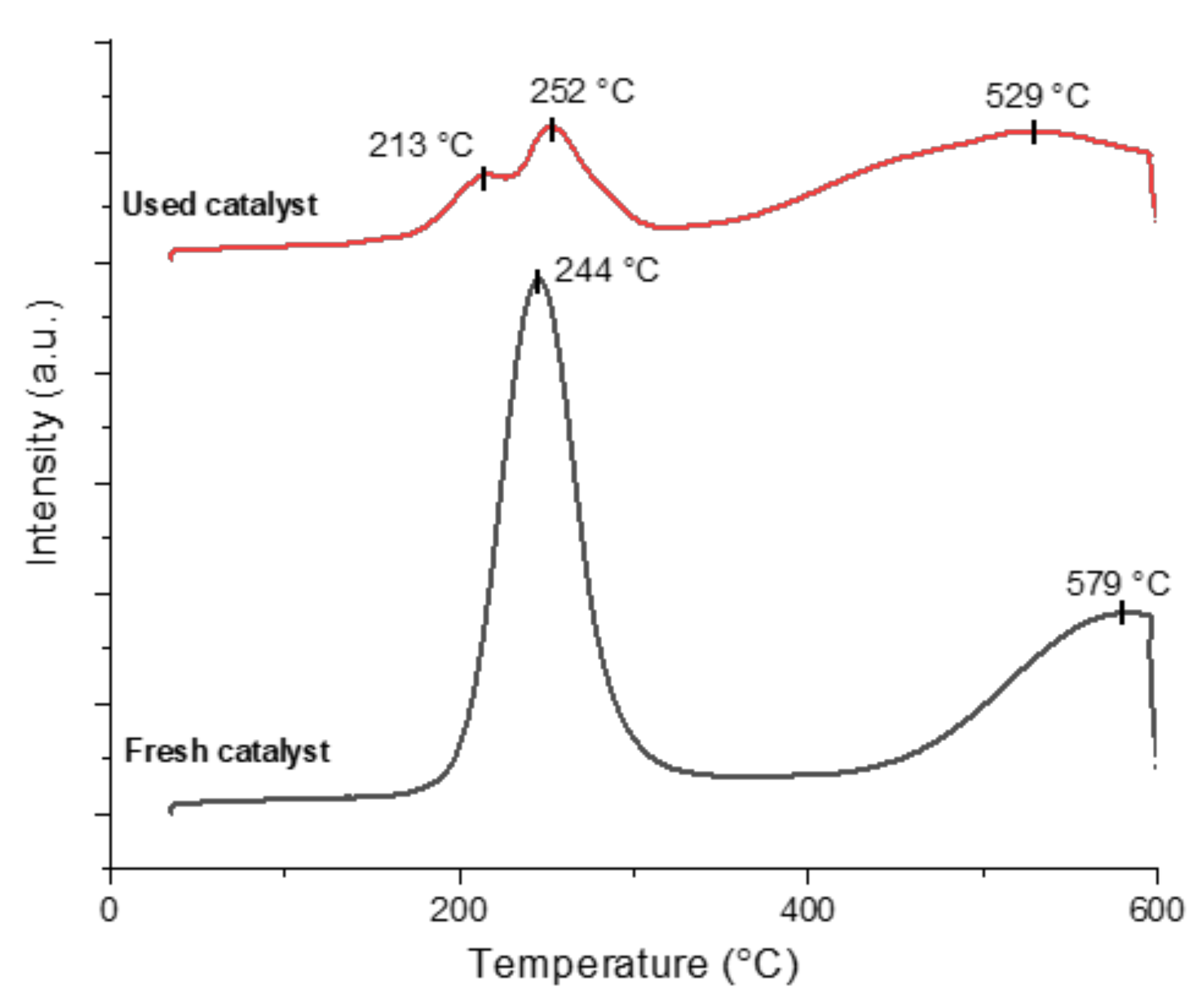
2.3. Catalyst Characterization
3. Materials and Methods
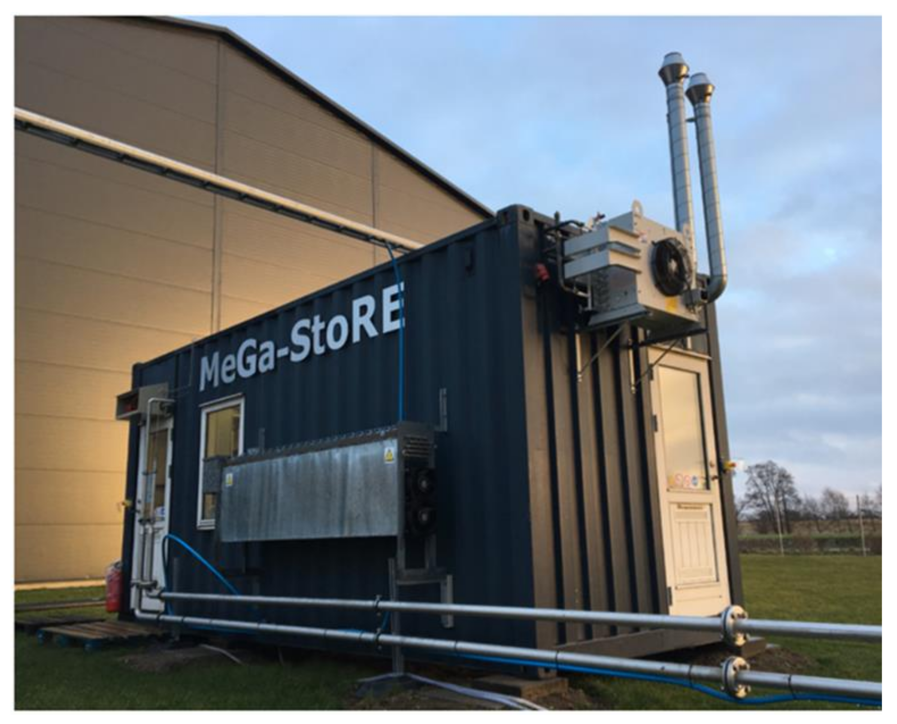
3.1. Methanation Reactor
3.2. Operational Procedure
3.3. Catalytic Tests
3.4. Catalyst Characterization
4. Conclusions
Author Contributions
Funding
Acknowledgments
Conflicts of Interest
References
- European Biogas Association. Annual Report 2018; European Biogas Association: Brussels, Belgium, 2018. [Google Scholar]
- Stern, J. The Future of Gas in Decarbonising European Energy Markets: The Need for a New Approach; The Oxford Institute for Energy Studies: Oxford, UK, 2017. [Google Scholar]
- Scarlat, N.; Dallemand, J.-F.; Fahl, F. Biogas: Developments and perspectives in Europe. Renew. Energy 2018, 129, 457–472. [Google Scholar] [CrossRef]
- Strauch, S.; Krassowski, J.; Singhal, A. Biomethane Guide for Decision Makers—Policy Guide on Biogas Injection into the Natural Gas Grid; Green Gas Grids; Deutsche Energie-Agentur (DENA): Berlin, Germany, 2013. [Google Scholar]
- Rasi, S.; Veijanen, A.; Rintala, J. Trace compounds of biogas from different biogas production plants. Energy 2007, 32, 1375–1380. [Google Scholar] [CrossRef]
- Walsh, J.L.; Ross, C.C.; Smith, M.S.; Harper, S.R. Utilization of biogas. Biomass 1989, 20, 277–290. [Google Scholar] [CrossRef]
- Ryckebosch, E.; Drouillon, M.; Vervaeren, H. Techniques for transformation of biogas to biomethane. Biomass Bioenergy 2011, 35, 1633–1645. [Google Scholar] [CrossRef]
- Villadsen, S.N.B.; Fosbøl, P.L.; Angelidaki, I.; Woodley, J.M.; Nielsen, L.P.; Møller, P. The Potential of Biogas; the Solution to Energy Storage. ChemSusChem 2019, 12, 2147–2153. [Google Scholar] [CrossRef] [PubMed]
- IEA Bioenergy Task 37. IEA Bioenergy Task 37—Country Reports Summary 2017, 2018; IEA Bioenergy: Paris, France, 2018. [Google Scholar]
- Yousef, A.M.; El-Maghlany, W.M.; Eldrainy, Y.A.; Attia, A. Upgrading biogas to biomethane and liquid CO2: A novel cryogenic process. Fuel 2019, 251, 611–628. [Google Scholar] [CrossRef]
- Friege, C.; Herbes, C. Some Basic Concepts for Marketing Renewable Energy. In Marketing Renewable Energy; Springer International Publishing: Cham, Switzerland, 2017. [Google Scholar] [CrossRef]
- Olah, G.A.; Goeppert, A.; Czaun, M.; Prakash, G.K.S. Bi-reforming of Methane from Any Source with Steam and Carbon Dioxide Exclusively to Metgas (CO–2H2) for Methanol and Hydrocarbon Synthesis. J. Am. Chem. Soc. 2013, 135, 648–650. [Google Scholar] [CrossRef]
- Witte, J.; Calbry-Muzyka, A.; Wieseler, T.; Hottinger, P.; Biollaz, S.M.A.; Schildhauer, T.J. Demonstrating direct methanation of real biogas in a fluidised bed reactor. Appl. Energy 2019, 240, 359–371. [Google Scholar] [CrossRef]
- Brooks, K.P.; Hu, J.; Zhu, H.; Kee, R.J. Methanation of carbon dioxide by hydrogen reduction using the Sabatier process in microchannel reactors. Chem. Eng. Sci. 2007, 62, 1161–1170. [Google Scholar] [CrossRef]
- Castellani, B.; Gambelli, A.M.; Morini, E.; Nastasi, B.; Presciutti, A.; Filipponi, M.; Nicolini, A.; Rossi, F. Experimental Investigation on CO2 Methanation Process for Solar Energy Storage Compared to CO2-Based Methanol Synthesis. Energies 2017, 10, 855. [Google Scholar] [CrossRef]
- Plechinger, M. Energy Watch. Available online: https://energywatch.eu/EnergyNews/Renewables/article12532617.ece (accessed on 2 December 2020).
- Martínez, J.; Hernández, E.; Alfaro, S.; López Medina, R.; Valverde Aguilar, G.; Albiter, E.; Valenzuela, M.A. High Selectivity and Stability of Nickel Catalysts for CO2 Methanation: Support Effects. Catalysts 2019, 9, 24. [Google Scholar] [CrossRef] [Green Version]
- Abelló, S.; Berrueco, C.; Montané, D. High-loaded nickel–alumina catalyst for direct CO2 hydrogenation into synthetic natural gas (SNG). Fuel 2013, 113, 598–609. [Google Scholar] [CrossRef]
- Olah, G.A.; Goeppert, A.; Czaun, M.; Mathew, T.; May, R.B.; Prakash, G.K.S. Single Step Bi-Reforming and Oxidative Bi-Reforming of Methane (Natural Gas) with Steam and Carbon Dioxide to Metgas (CO-2H2) for Methanol Synthesis: Self-Sufficient Effective and Exclusive Oxygenation of Methane to Methanol with Oxygen. J. Am. Chem. Soc. 2015, 137, 8720–8729. [Google Scholar] [CrossRef] [PubMed]
- El Sibai, A.; Rihko Struckmann, L.K.; Sundmacher, K. Model-Based Optimal Sabatier Reactor Design for Power-to-Gas Applications. Energy Technol. 2017, 5, 911–921. [Google Scholar] [CrossRef]
- Rönsch, S.; Schneider, J.; Matthischke, S.; Schlüter, M.; Götz, M.; Lefebvre, J.; Prabhakaran, P.; Bajohr, S. Review on methanation—From fundamentals to current projects. Fuel 2016, 166, 276–296. [Google Scholar] [CrossRef]
- Matthischke, S. Unsteady-state methanation of carbon dioxide in a fixed-bed recycle reactor—Experimental results for transient flow rate ramps. Fuel Process. Technol. 2016, 153, 87–93. [Google Scholar] [CrossRef]
- Fache, A.; Marias, F.; Guerré, V.; Palmade, S. Optimization of fixed-bed methanation reactors: Safe and efficient operation under transient and steady-state conditions. Chem. Eng. Sci. 2018, 192, 1124–1137. [Google Scholar] [CrossRef]
- Bartholomew, C.H. Mechanisms of catalyst deactivation. Appl. Catal. A Gen. 2001, 212, 17–60. [Google Scholar] [CrossRef]
- Abatzoglou, N.; Boivin, S. A review of biogas purification processes. Biofuels Bioprod. Biorefin. 2009, 3, 42–71. [Google Scholar] [CrossRef]
- Persson, M.; Jönsson, O.; Wellinger, A. Biogas Upgrading to Vehicle Fuel Standards and Grid Injection Biogas; Upgrading I; IEA Bioenergy: Paris, France, 2006. [Google Scholar]
- Allegue, L.B.; Hinge, J. Biogas Upgrading Evaluation of Methods for H2S Removal; Danish Technological Institute: Taastrup, Denmark, 2014; pp. 1–31. [Google Scholar]
- Rabou, L.P.L.M.; Bos, L. High efficiency production of substitute natural gas from biomass. Appl. Catal. B Environ. 2012, 111–112, 456–460. [Google Scholar] [CrossRef] [Green Version]
- Gao, J.; Wang, Y.; Ping, Y.; Hu, D.; Xu, G.; Gu, F.; Su, F. A thermodynamic analysis of methanation reactions of carbon oxides for the production of synthetic natural gas. RSC Adv. 2012, 2, 2358–2368. [Google Scholar] [CrossRef]
- Stangeland, K.; Kalai, D.; Li, H.; Yu, Z. CO2 Methanation: The Effect of Catalysts and Reaction Conditions. Energy Procedia 2017, 105, 2022–2027. [Google Scholar] [CrossRef]
- Jürgensen, L.; Ehimen, E.A.; Born, J.; Holm-Nielsen, J.B. Dynamic biogas upgrading based on the Sabatier process: Thermodynamic and dynamic process simulation. Bioresour. Technol. 2015, 178, 323–329. [Google Scholar] [CrossRef] [PubMed]
- Jekaterina, P.; Gatis, B.; Darja, M. Modeling of the Adiabatic and Isothermal Methanation Process. Environ. Clim. Technol. 2011, 6, 79–84. [Google Scholar] [CrossRef] [Green Version]
- Moon, D.H.; Lee, S.M.; Ahn, J.Y.; Nguyen, D.D.; Kim, S.S.; Chang, S.W. New Ni-based quaternary disk-shaped catalysts for low-temperature CO2 methanation: Fabrication, characterization, and performance. J. Environ. Manag. 2018, 218, 88–94. [Google Scholar] [CrossRef] [PubMed]
- Wu, H.; Yin, K.; Qi, W.; Zhou, X.; He, J.; Li, J.; Liu, Y.; He, J.; Gong, S.; Li, Y. Rapid Fabrication of Ni/NiO@CoFe Layered Double Hydroxide Hierarchical Nanostructures by Femtosecond Laser Ablation and Electrodeposition for Efficient Overall Water Splitting. ChemSusChem 2019, 12, 2773–2779. [Google Scholar] [CrossRef]
- Dannesboe, C.; Hansen, J.B.; Johannsen, I. Removal of sulfur contaminants from biogas to enable direct catalytic methanation. Biomass Convers. Biorefin. 2019. [Google Scholar] [CrossRef] [Green Version]
- Frilund, C.; Simell, P.; Kaisalo, N.; Kurkela, E.; Koskinen-Soivi, M.-L. Desulfurization of Biomass Syngas Using ZnO-Based Adsorbents: Long-Term Hydrogen Sulfide Breakthrough Experiments. Energy Fuels 2020, 34, 3316–3325. [Google Scholar] [CrossRef]
- Hepola, J.; Simell, P.; Kurkela, E.; Ståhlberg, P. Sulphur poisoning of nickel catalysts in catalytic hot gas cleaning conditions of biomass gasification. In Studies in Surface Science and Catalysis; Delmon, B., Froment, G.F., Eds.; Elsevier: Amsterdam, The Netherlands, 1994; Volume 88, pp. 499–506. [Google Scholar]
- Gac, W.; Zawadzki, W.; Rotko, M.; Słowik, G.; Greluk, M. CO2 Methanation in the Presence of Ce-Promoted Alumina Supported Nickel Catalysts: H2S Deactivation Studies. Top. Catal. 2019, 62, 524–534. [Google Scholar] [CrossRef] [Green Version]
- Khzouz, M.; Gkanas, E.I. Experimental and Numerical Study of Low Temperature Methane Steam Reforming for Hydrogen Production. Catalysts 2017, 8, 5. [Google Scholar] [CrossRef] [Green Version]
- He, Z.; Wang, X.; Liu, R.; Gao, S.; Xiao, T. Perfomances of different additives on NiO/γ-Al2O3 catalyst in CO methanation. Appl. Petrochem. Res. 2016, 6, 235–241. [Google Scholar] [CrossRef] [Green Version]
- Gao, Y.; Meng, F.; Ji, K.; Song, Y.; Li, Z. Slurry phase methanation of carbon monoxide over nanosized Ni–Al2O3 catalysts prepared by microwave-assisted solution combustion. Appl. Catal. A Gen. 2016, 510, 74–83. [Google Scholar] [CrossRef]
- Zhu, L.; Yin, S.; Wang, X.; Liu, Y.; Wang, S. The catalytic properties evolution of HZSM-5 in the conversion of methanol to gasoline. RSC Adv. 2016, 6, 82515–82522. [Google Scholar] [CrossRef]
- Li, P.; Park, Y.H.; Moon, D.J.; Park, N.C.; Kim, Y.C. Carbon Deposition Onto Ni-Based Catalysts for Combined Steam/CO2 Reforming of Methane. J. Nanosci. Nanotechnol. 2016, 16, 1562–1566. [Google Scholar] [CrossRef] [PubMed]
- Dou, X.; Veksha, A.; Chan, W.P.; Oh, W.-D.; Liang, Y.N.; Teoh, F.; Mohamed, D.K.B.; Giannis, A.; Lisak, G.; Lim, T.-T. Poisoning effects of H2S and HCl on the naphthalene steam reforming and water-gas shift activities of Ni and Fe catalysts. Fuel 2019, 241, 1008–1018. [Google Scholar] [CrossRef]
- Méndez-Mateos, D.; Barrio, V.L.; Requies, J.M.; Cambra, J.F. A study of deactivation by H2S and regeneration of a Ni catalyst supported on Al2O3, during methanation of CO2. Effect of the promoters Co, Cr, Fe and Mo. RSC Adv. 2020, 10, 16551–16564. [Google Scholar] [CrossRef]
- Albertazzi, S.; Basile, F.; Brandin, J.; Einvall, J.; Fornasari, G.; Hulteberg, C.; Sanati, M.; Trifirò, F.; Vaccari, A. Effect of fly ash and H2S on a Ni-based catalyst for the upgrading of a biomass-generated gas. Biomass Bioenergy 2008, 32, 345–353. [Google Scholar] [CrossRef]
- Luisetto, I.; Tuti, S.; Battocchio, C.; Lo Mastro, S.; Sodo, A. Ni/CeO2–Al2O3 catalysts for the dry reforming of methane: The effect of CeAlO3 content and nickel crystallite size on catalytic activity and coke resistance. Appl. Catal. A Gen. 2015, 500, 12–22. [Google Scholar] [CrossRef]
- Awad, A.; Salam, A.; Abdullah, B. Thermocatalytic decomposition of methane/methanol mixture for hydrogen production: Effect of nickel loadings on alumina support. AIP Conf. Proc. 2017, 1891, 020030. [Google Scholar] [CrossRef] [Green Version]


| Reactors | R1 | R2 | R3 | R4 |
|---|---|---|---|---|
| Expected temperature (°C) | 471 | 488 | 421 | 348 |
| Actual reactor temperature (°C) | 485 | 485 | 475 | 358 |
| Catalyst | SBET (m2/g) |
|---|---|
| Fresh catalyst | 170.7 |
| Used catalyst | 95.1 |
Publisher’s Note: MDPI stays neutral with regard to jurisdictional claims in published maps and institutional affiliations. |
© 2020 by the authors. Licensee MDPI, Basel, Switzerland. This article is an open access article distributed under the terms and conditions of the Creative Commons Attribution (CC BY) license (http://creativecommons.org/licenses/by/4.0/).
Share and Cite
Gaikwad, R.; Villadsen, S.N.B.; Rasmussen, J.P.; Grumsen, F.B.; Nielsen, L.P.; Gildert, G.; Møller, P.; Fosbøl, P.L. Container-Sized CO2 to Methane: Design, Construction and Catalytic Tests Using Raw Biogas to Biomethane. Catalysts 2020, 10, 1428. https://doi.org/10.3390/catal10121428
Gaikwad R, Villadsen SNB, Rasmussen JP, Grumsen FB, Nielsen LP, Gildert G, Møller P, Fosbøl PL. Container-Sized CO2 to Methane: Design, Construction and Catalytic Tests Using Raw Biogas to Biomethane. Catalysts. 2020; 10(12):1428. https://doi.org/10.3390/catal10121428
Chicago/Turabian StyleGaikwad, Rohit, Sebastian N. B. Villadsen, Jan Pihl Rasmussen, Flemming Bjerg Grumsen, Lars Pleth Nielsen, Gary Gildert, Per Møller, and Philip Loldrup Fosbøl. 2020. "Container-Sized CO2 to Methane: Design, Construction and Catalytic Tests Using Raw Biogas to Biomethane" Catalysts 10, no. 12: 1428. https://doi.org/10.3390/catal10121428
APA StyleGaikwad, R., Villadsen, S. N. B., Rasmussen, J. P., Grumsen, F. B., Nielsen, L. P., Gildert, G., Møller, P., & Fosbøl, P. L. (2020). Container-Sized CO2 to Methane: Design, Construction and Catalytic Tests Using Raw Biogas to Biomethane. Catalysts, 10(12), 1428. https://doi.org/10.3390/catal10121428