Abstract
Calcium titanate mixed metal oxides with different contents were used as supports for NiMo catalyst prepared by the sol–gel method. The activities of these catalysts were tested in the catalytic decomposition of waste polypropylene (PP) for the synthesis of carbon nanotubes (CNTs) using a single-stage chemical vapor deposition technique. The physico-chemical properties of the catalysts and deposited carbon over the catalysts were checked by X-ray diffraction (XRD), scanning electron microscopy (SEM), temperature-programmed reduction (TPR), N2 physisorption, transmission electron microscopy (TEM), Raman spectroscopy, and thermogravimetric analysis (TGA). The TEM and XRD results presented a high dispersion of the active metal species on the surface of the support materials. The result showed that increasing the support content led to an increased crystallite size of the catalysts and a resultant reduction in CNTs yield from 44% to 35%. NiMo-supported CaTiO3 catalyst displayed good catalytic activity and stability toward CNTs growth. Furthermore, the effect of calcination temperature on the morphology, yield, and quality of CNTs was also studied, and it was observed that thermal treatment up to 700 °C could produce well graphitized, high-quality, and high-yield CNTs from the waste PP.
1. Introduction
Carbon nanotubes (CNTs) are one-dimensional graphene sheets rolled up into seamless tubes and they are generally classified according to their number of wall(s) as single-walled carbon nanotubes (SWCNTs), double-walled carbon nanotubes (DWCNTs), and multi-walled carbon nanotubes (MWCNTs) [1,2]. CNTs possess excellent properties such as large surface area, high tensile strength and stiffness, good electrical conductivity, extraordinary aspect ratio, etc. [3,4,5]. Therefore, such properties made them attractive materials for different applications as reinforcement in composites, sensors, field emitters, nano-electronics and energy storage, fillers in membranes for wastewater purifications and gas separation, etc. [6,7,8,9,10,11].
Considering the enormous global demand and application of CNTs, it is plausible that the cost of production is minimized while yield and quality are maximized. Accordingly, ‘sleeping treasure’ waste polypropylene (PP) has been widely researched as a key material and as a cheap hydrocarbon feedstock for CNTs synthesis [12,13,14,15,16,17]. Recently, Wang et al. [18] synthesized high yield (93%) filamentous carbon from the catalytic pyrolysis of waste PP over Ni-based catalyst in a two-stage fixed bed reactor system. In addition, Yao and Wang [19] obtained an improved yield of bamboo-like MWCNTs with average diameter of 22 nm during the catalytic decomposition of PP, and they revealed that the catalyst component and preparation method significantly affect the carbon yield. The growing demand and consumption of PP materials from different sectors such as in packaging, automobile, etc., resulted in their increased prevalence in the waste stream, since it is expected that most consumed plastics should also constitute the highest waste given their non-biodegradability. Consequently, PP is estimated to contribute over 24.3% to the waste stream globally, and it is also the largest class of waste found in municipal solid wastes (MSW) [20,21].
Amongst the methods employed for CNT production, the chemical vapor deposition (CVD) technique has emerged as the most suitable high-quality, high-purity, relatively low-cost and mass-producing technique for CNT production [3,22]. Other than CVD parametric conditions such as synthesis temperature, pressure, etc., which are necessary for CNT growth, catalyst and catalyst composition play a very crucial role in providing the desired nanoparticle size, morphology, and stability [23,24,25]. Studies have shown that transition metals of Ni, Fe, and Co are appropriate metal catalysts in CNT growth and nucleation [2,26]. It is also evident that the alloys of these transition metals such as Ni–Mo [15,22,27], Fe–Mo [28], Co–Mo [8,29], Ni–Al [30], Fe–Ni [31,32], etc., offer improved and enhanced catalytic performance and selectivity toward high yield and highly graphitized CNTs than monometallic nanoparticles [33]. Additionally, catalyst support is an essential factor that can strongly affect the size distribution of catalyst particles and the dispersion of active metal [34]. As reported in the literature, there is a strong link between the catalyst particle size and CNTs diameter [16,35]. Modekwe et al. [36] in their recent study reported that the catalyst preparation method was influential on the degree of dispersion of catalyst active metal on the support, which inherently determines the catalyst particle size and the resultant CNTs diameter. The CNT growth mode, average diameter, quality, and yield are heavily dependent on the structural and textural properties of the substrate [35]. Therefore, the choice of catalyst support is very important in the synthesis of CNTs. Additionally, thermally stable support is efficient in hydrocarbon cracking, especially in minimizing catalyst deactivation [34]. Since all metallic catalysts are prone to sintering, support components effectively inhibit the coalescence of catalytic metal nanoparticles and also inhibit subsurface diffusion of the catalyst particles [35,37,38]. Therefore, the support material has to be thermally stable and more resistant to sintering than the active metal catalyst species [37]. To date, metal oxide supports such as MgO, TiO2, SiO2, CaO, etc., have been widely studied. In addition, binary oxides such as Al2O3–TiO2 [39], MgO–La2O3 [40], etc., have also been investigated and were reported to exhibit higher and more sustaining stability than single metal oxide supports [39,41]. Awadallah et al. [42] investigated the effect of different Ti contents on the Ni supported alumina–titania binary oxides during the catalytic decomposition of methane to hydrogen. They reported that superior catalytic activity and stability were obtained with Ni/TiO2 (25%)–Al2O3 relative to the single metal oxide 60%Ni/Al2O3 catalyst. Again, with the Ni/TiO2 (25%)–Al2O3 catalyst, an improved hydrogen yield of 59% was obtained compared to 42% for the 60%Ni–Al2O3 catalyst after 6.5 h under similar reaction conditions.
CNT growth from hydrocarbons is greatly restricted by deactivation of the catalyst due to coke formation, and employing a catalyst support with good stability could assist in enhancing the catalytic performance toward improved yield [43]. Calcium titanate, CaTiO3, is a binary-mixed metal oxide in a class of perovskite-type catalyst with general formula ABO3 [44,45,46]. CaTiO3 has been studied as a good catalyst whose catalytic activity and performance overcome the limitations of TiO2 and CaO-based heterogeneous catalysts such as reduced thermal stability of the anatase phase of TiO2 at high temperatures, etc. [47,48,49]. These materials are relatively inexpensive and are found to be thermally stable when calcined at higher temperatures up to 1000 °C, unlike other titanate-mixed perovskite, which is susceptible to sintering at high temperatures, hence reducing the dispersion of active metal, leading to reduced catalytic activity [42,50,51]. For example, Yahya and co-workers [52] studied and compared the catalytic activities of CaTiO3 and commercial CaO as catalysts during the catalytic production of biodiesel from waste cooking oil. They found that for 1 wt % CaTiO3 catalyst loading calcined at 400 °C, high biodiesel yield up to 80% was produced compared to commercial CaO catalyst with 60% biodiesel yield under the same reaction conditions of methanol to oil ratio of 15:1 at 65 °C for 60 min. In a patented study by Baker and Summit [53], the catalytic activity of CaO–TiO2 was compared with fresh commercial silica–alumina (SiO2–Al2O3) catalyst containing about 13% alumina during the catalytic cracking of light gas oil (East Texas) feed in a fixed bed reactor at a boiling range of 490–700 °F under atmospheric pressure. Their result showed that CaO–TiO2 catalyst produced a higher yield (24.4 wt %) of more olefinic C5–430 °F gasoline with better performance (with bromine number of about 81 cg./mL) than C5–430 °F gasoline yield of 23.0 wt % and 40 cg/mL bromine number obtained with SiO2–Al2O3 catalyst. Similarly, in the same invention by Baker and Summit, 5% NiO supported on 95% CaO–TiO2 catalyst was also utilized as a reforming catalyst in the dehydrogenation of methylcyclopentene feed into the aromatic hydrocarbon containing benzene and its activity was compared with the conventional reforming catalyst 90% Al2O3–10% MoO3 under 2/1 H2 to hydrocarbon dilution at 200 p.s.i.g. (pounds per square in gauge) and 975 °F; their result showed that more aromatic hydrocarbons at about 28% of feed were produced with 5% NiO–95% CaO–TiO2 catalyst relative to the conventional reforming 90% Al2O3–10% MoO3 catalyst [53].
Although several studies have investigated the activity of NiMo-based catalyst to catalyze the decomposition of hydrocarbons for CNTs production from single pure and waste polymers, available studies on NiMo catalysts for the pyrolysis of waste PP using a single-stage CVD technique are rather limited. Additionally, the yield and quality of as-produced carbon deposited over NiMo-supported CaTiO3 catalyst using waste PP have not been systematically investigated. Therefore, this study explored the use of bimetallic NiMo-supported CaTiO3 catalysts in the valorization of waste PP into CNTs using a single-stage chemical vapor deposition method. The effect of catalyst support loading and catalyst thermal treatment condition on the yield, quality, and morphology of deposited carbon were also studied.
2. Results and Discussion
2.1. Catalyst Synthesis and Characterization
The XRD patterns of NiMo/CaTiO3 catalysts with different CaTiO3 content (NMC412 and NMC414) are shown in Figure 1. The XRD patterns of both NiMo/CaTiO3 catalysts reveal characteristic diffraction peaks of NiO at 2θ = 37.2°, 43.2°, 62.9°, 75.3° and 79.4° that correspond to the (1 1 1), (2 0 0), (2 2 0), (3 1 1), and (2 2 2) planes, respectively, were observed [30,54]. Six resolved peaks attributed to CaTiO3 at 2θ = 33.0°, 47.5°, 59.2°, 62.9° 69.54°, and 75.3° were observed with NMC412 catalyst, while NMC414 catalyst shows distinctive peaks at 2θ = 33.2°, 39.8°, 41.0°, 47.6°, 59.2°, 62.9°, 69.4°, and 75.3° [45,55]. For both catalysts, NiO and CaTiO3 crystals could be identified on the catalyst surface. However, the XRD pattern of NMC414 catalyst show more sharp diffraction peaks for CaTiO3 (2θ = 33.2°), signifying the degree of increase in the crystallite size of the catalyst. Similarly, NiO of large particle size was produced by the NMC414 catalyst. The corresponding average crystallite size of the main phases present in both catalysts is 9.2 nm and 10.1 nm for NMC412 and 11.4 nm and 14.8 nm for NMC414. The above result is in support of Scherrer’s equation, which links large metal crystallite sizes to sharp and intense diffraction peaks, while broad peaks are associated with smaller crystallite-sized particles [56]. For both catalysts, several overlaps were observed: the diffraction peaks at 2θ = 59.2° and 69.4° overlap with the metastable phases of CaMoO4. Again, the peaks at 2θ = 37.2°, 43.2° 62.9°, and 75.3° were observed to overlap with NiMoO4, NiO, and/or CaTiO3 phases. Diffraction peaks at 2θ = 24.3°, 35.7°, and 49.4° are linked to anatase TiO2. A similar XRD pattern was also reported for CaTiO3 by Salinas et al. [55], where an anatase TiO2 phase was observed at 2θ = 24.5°.
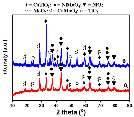
Figure 1.
XRD pattern of NiMo/CaTiO3 catalysts: (A) NMC412 and (B) NMC414.
The morphology of both catalysts (NMC412 and NMC414) obtained from TEM are depicted in Figure 2. The NMC414 catalyst showed a random irregular structure with an estimated mean average particle diameter of about 16.7 nm, while the NMC412 catalyst displayed an almost well-rounded platelet-like structure with an estimated mean diameter of about 9 nm; they also depict a good dispersion of particles on the surface of the support. These results are consistent with the XRD patterns for the samples. Liu et al. [32] reported similar smaller Ni particle sizes between 8 and 13 nm for Ni-based catalysts. Therefore, TEM images showed that by increasing the support content in the catalyst, the diameter of Ni particles also increases; hence, large particle size distribution was observed on the NMC414 catalyst compared to the NMC412 catalyst.
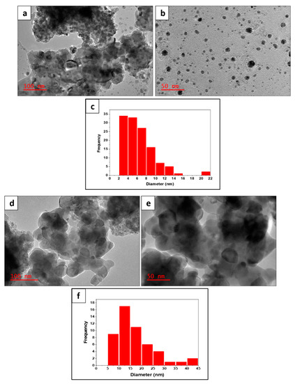
Figure 2.
TEM images and particle size distribution histograms of NiMo/CaTiO3 catalysts containing different CaTiO3 content: (a–c) NMC412 and (d–f) NMC414.
Temperature-programmed reduction (TPR) investigation was carried out to study the reducibility of both catalysts in order to deduce their interaction between the metal oxide (NiO) species and the CaTiO3 support. The TPR profile of two catalysts under study is shown in Figure 3. Distinct and broad reduction peaks were observed for both catalysts with different CaTiO3 compositions. For the NMC414 catalyst, the first reduction peak in the range of 350–427 °C with two well-defined divisions, with maximum at 380 °C and 403 °C, were attributed to the reduction of Ni2+ in the crystalline NiO phase [30] and the reduction of TiO2 phases (whose single phase was detected by XRD), respectively [55]. It has been reported that the reduction of unsupported NiO to atomic Ni occurs around 200 °C, while supported NiO is reduced at a rather higher temperature range [57]. For the NMC412 catalyst, the first reduction peak appeared at the range of 420–538 °C with a maximum at 480 °C, which was attributed to the reduction of NiO. This higher reduction temperature could be due to the smaller NiO particle size for the NMC412 catalyst compared to the NMC414 catalyst, since it was reported that catalysts with small metal oxide particles require high temperature to be reduced to their metallic stable forms [32].
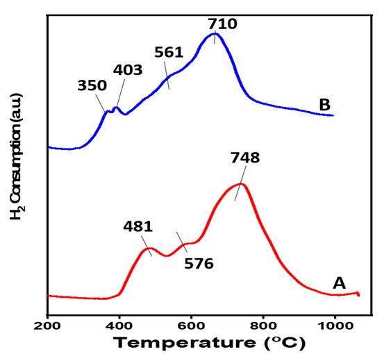
Figure 3.
Temperature-programmed reduction (TPR) profile of NiMo/CaTiO3 catalysts containing different CaTiO3 support contents; (A) NMC412 and (B) NMC414.
Another broad peak that appeared as a shoulder at 576 °C was observed for the NMC412 catalyst, and the similar peak slightly disappears for the NMC414 catalyst due to the appearance of segregated phases. The broad peak in the range of 570–610 °C with a maximum at 576 °C could be attributed to the reduction of less thermally stable NiO–CaTiO3 compounds as well as the reduction of Mo species as confirmed by XRD [57]. The interaction between NiO and CaTiO3 resulted in the incorporation of Ca2+ into NiO crystallites, which poses difficulty in the disruption of the Ni–O bond [58].
A larger and stronger peak was observed at a high reduction temperature for the NMC412 catalyst in the temperature range of 712–802 °C with a maximum at 748 °C; this peak could be related to the complete reduction of the MoO2 phase as shown in the XRD pattern due to its metallic form and could be associated to the reduction of the Ni–Mo–O phase. This could also be attributed to the reduction of the thermally stable calcium compound CaMoO4, whose reduction has been reported to begin at a temperature above 700 °C [55]. By increasing the support content in the bulk catalyst (i.e., NMC414), the reduction peak at 650–782 °C has a maximum at 710 °C, which was lower than the observed peak for the NMC412 catalyst, signifying a reduced interaction between the catalyst metal oxide species and the support. Hence, strong and more interaction was observed for the NMC412 catalyst (that is, between the metal oxide species) than for the NMC414 catalyst.
The morphology of the two catalysts with different support content was determined by SEM analysis, as shown in Figure 4. These results showed almost dissimilar aggregates of catalyst particles for both catalysts. The NMC412 catalyst depicts more porous, more defined morphology and smoother particle than the NMC414 catalyst. The NMC414 catalyst displayed a compacted-stack structure, which could be due to the presence of more CaTiO3 content in the catalyst resulting in different aggregated degrees of the catalyst particles.
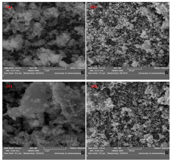
Figure 4.
SEM images of prepared NiMo/CaTiO3 catalysts containing different CaTiO3 content: (a,b) NMC412, (c,d) NMC414.
Energy-dispersive X-ray spectroscopy (EDXS) analysis was used to determine the elements present on some spots on the catalyst surface, as shown in Figure 5. Analysis of EDXS result peaks in keV showed that all elements of interest in the catalyst mix were all found. Table S3 disclosed the composition of elements in NMC412 and NMC414 catalysts, respectively. This also revealed that the stoichiometric ratio of CaTiO3 present in Figure 5B is higher than that in Figure 5A.
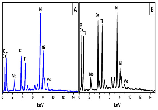
Figure 5.
Energy-dispersive X-ray spectroscopy (EDXS) spectra of NiMo/CaTiO3 catalysts containing different CaTiO3 content: (A) NMC412 and (B) NMC414.
2.2. Effect of Support Composition and Content on the Microstructure, Yield, and Quality of CNTs
The microstructure of the carbon nanomaterial deposited on the surface of catalysts is shown in Figure 6. The carbon deposits were majorly a filamentous type of carbon in the tubular-like form identified as multi-walled carbon nanotubes (MWCNTs) with their length up to a few micrometers. The numbers of the walls were mainly in the range of 10–15 (see high-resolution TEM images in Figure 6a,b). The absence of radial breathing mode (RBM), a characteristic of SWCNT [59], was confirmed in Figure S1 for all as-grown CNTs over both catalysts. A very small proportion of amorphous and disordered carbon was also detected. It is noteworthy to mention that amongst the MWCNTs deposited on the surface of the NMC414 catalyst, carbon nanofibers (CNFs) with few broken and deformed nanotubes were also deposited. The diameter distribution of MWCNTs obtained from the two different catalysts of diverse support content is shown in Figure 6. Long, smooth, and twisted MWCNTs with outer diameters ranging from 5 to 35 nm were obtained from MWCNTs deposited over the NMC412 catalyst; this correlates with the XRD and TEM particle size results. Rough-edged and larger diameter MWCNTs with an outer diameter in the range of 12 to 36 nm were produced over the NMC414 catalyst. It could be suggested that a smaller particle-sized catalyst yielded long, smoother, and small diameter MWCNTs. This result agrees with what is reported in the literature: the size of active metal particles controls the diameter as well as growth of CNTs [60,61].
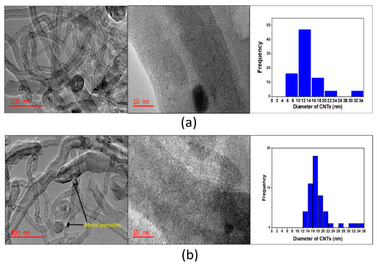
Figure 6.
TEM images and diameter distribution histograms of as-grown carbon nanotubes (CNTs) over NiMo/CaTiO3 catalysts containing different support content: (a) NMC412, (b) NMC414.
The yield of CNTs deposited over the NMC412 catalyst was obtained to be 44%, while the NMC414 catalyst yielded about 35% CNTs. The above result also reveals that support material composition and content is significant and has a noticeable influence on the catalytic performance toward CNTs yield. Similarly, the above result could be due to the smaller metal particle size of the NMC412 catalyst relative to the NMC414 catalyst, as confirmed from XRD and TEM results. According to the study by Yao et al. [56] they reported that Ni/α–Al2O3 catalyst with a smaller metal particle size produced higher CNTs yield (26.1 wt. %) than Ni/γ–Al2O3 catalyst (21.1 wt. %). The authors suggested this could probably be due to smaller metal particles on the catalyst surface, which facilitated carbon atom diffusion, nucleation, and nanotubes growth at the interface, ultimately resulting in higher CNTs yield. It could be confirmed that there is a connection among CNTs yield, the crystallite size of NiO, and the CaTiO3 content in the catalyst, which resulted in a higher CNTs yield. Accordingly, smaller crystallite-sized active sites (in this case NiO) result in high carbon yield [61].
To study the quality and graphitization degree of as-produced CNTs, Raman analysis was conducted. The Raman spectra of MWCNTs produced over the two catalysts under study are illustrated in Figure S1. Three different bands are seen on the spectrum for each CNTs; the G-band at about 1580 cm−1 is an indication of the presence of ordered and graphitized carbon. The D-band around 1352 cm−1 is attributed to the presence of amorphous or disordered carbon atoms in the CNTs [62], while the G’ band (2D-band) obtained at 2691 cm−1 is linked to the second-order two-photon process. It indicates the presence of parallel graphitic layers in CNTs [63]. The peak intensity ratios IG/ID and IG’/IG are used to investigate the quality and degree of graphitization of CNTs; it is also an indication of defects in the graphitic structure [22]. Therefore, a higher IG/ID ratio suggests high-quality and well-graphitized CNTs, while a high IG’/IG ratio also suggests high-purity CNTs [64]. A very distinctive 2D-band (G’ band) appeared in all CNTs deposited over both catalysts, indicating that CNTs formed from both catalysts are of high purity and possess more parallel graphitic layers. For the MWCNTs deposited over the NMC412 catalyst, an IG/ID ratio of 1.15 and IG’/IG ratio of 0.80 were obtained; while the produced MWCNTs over the NMC414 catalyst have an IG/ID ratio of 0.96 and an IG’/IG ratio of 0.84. The above results suggest the presence of defects on the CNTs obtained from both catalysts, but the CNTs deposited over the NMC412 catalyst possess fewer defects and have higher quality and a higher degree of structural ordering than those obtained over the NMC414 catalyst. Therefore, it could be concluded that the microstructure, yield, and quality of MWCNTs obtained are strongly affected by the CaTiO3 content in the parent catalyst because of the optimum interaction between the support and the Ni-active metal. It is worthwhile comparing this work with other studies in the literature that employed the use of waste PP as a carbon source for CNTs synthesis with respect to the quality and yield of CNTs obtained. Mishra et al. [65] also utilized a single-stage CVD reactor in their study; waste PP was the used carbon precursor in the presence of unsupported Ni catalyst. They reported a good graphitic CNTs yield of 19% with their outer diameter in the range of 10–20 nm. Bajad and co-workers [66] also synthesized CNTs from waste PP in a batch reactor using NiMo-supported MgO catalyst; their obtained yield was 3.2 g CNTs/6 g PP with 40–60 nm outer diameter CNTs of lower quality reported.
It could be concluded that CaTiO3 support in the NiMo catalyst mix resulted in small diameter and a high yield of CNTs of good quality.
2.3. The Effect of Calcination Temperatures on the Yield and Quality of CNTs
The effect of variation in calcination temperature (600 °C, 700 °C, and 800 °C) on NiMo/CaTiO3 catalyst prepared at molar ratios of 4:1:2 (designated as NMC412) was studied to evaluate its influence on the yield, microstructure, and quality of as-produced CNTs. The investigation was carried out on NMC412 catalyst calcined at 600 °C, 700 °C, and 800 °C.
The textural property of the NMC412 catalyst at different calcination temperatures was obtained via N2 physisorption at −196 °C (see Table 1 for the results). It could be observed that there is a progressive decrease in the specific surface area and pore volume of the catalysts as the calcination temperature increases from 600 to 800 °C. This result is expected based on what was reported in the literature: at high calcination temperature, the wall porous structures of materials collapse, and this leads to their lower total surface area [41,58]. Furthermore, the low BET (Brunauer-Emmett-Teller) surface area for all the catalyst calcined from 600 to 800 °C could be due to the agglomeration of metal particles at elevated temperature or due to catalyst precursor (additive) composition and/or catalyst preparation technique [37]. Although no direct comparison could be obtained from the literature, studies by Pfaff [50] and Liu and co-workers [67] presented similar reductions in surface and pore volume with increasing calcination temperature.

Table 1.
Textural property of the NMC412 catalyst at different calcination temperatures.
The structural changes in the phases of NMC412 catalysts calcined at different temperatures were evaluated using XRD analysis, as depicted in Figure 7. The individual peaks corresponding to different phases were identified and labeled in the XRD spectra, as shown in Figure 7. It could be observed that as the calcination temperature increases, the identified peaks become sharper and more elongated, indicating an increased crystallite size of the catalysts [56] with increasing calcination temperature, while broader and shortened peaks disclose smaller crystallite size (600 °C < 700 °C < 800 °C), as shown in Table 2. A major change was identified with the 800 °C calcined catalyst with the appearance of additional metal stable phases of NiMoO4, CaMoO4, and tricalcium dititanium oxide (Ca3Ti2O7) phases (the Ca3Ti2O7 compound is a double perovskite sheet interwoven with CaO) [50]. The presence of thermally stable compounds inhibits catalyst deactivation and the agglomeration of NiO particles on the catalyst surface, disallowing the formation of excessive larger NiO particles [61]. This confirms that high calcination temperatures result in the emergence of thermally stable compounds in the catalysts, which builds up a strong interaction between the catalyst-active metal and the support. In addition, it was also observed that the crystallite size of all the phases of interest—that is, NiO and CaTiO3 (Ca3Ti2O7)—increased as the thermal treatment temperature increased from 600 to 800 °C, as shown in Table 2.
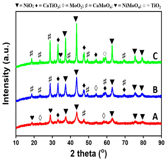
Figure 7.
XRD pattern of the prepared NiMo/CaTiO3 (NMC412) catalysts calcined at different temperatures: (A) 600 °C, (B) 700 °C, and (C) 800 °C.
Table 2.
Crystallite sizes of phases NiO and CaTiO3 (or Ca3Ti2O7 as the case may be) present in the NMC412 catalyst prepared at different calcination temperatures as obtained from XRD analysis.
TPR was used to study the interaction between the Ni active phase and the support material of the catalysts prepared at different calcination temperatures, as illustrated in Figure 8. From the TPR profile, the peaks at 460 °C, 480 °C, and 484 °C for 600 °C, 700 °C, and 800 °C calcined catalysts respectively, could be attributed to the high-temperature reduction of the NiO species to Ni0 due to its interaction with the support material. Again, the small crystallite size of the metal oxide could be the reason also for its high reduction temperature. It is also necessary to recall that crystallites with small size require high temperature to be reduced to their metallic form [32,68]. The profile for the 800 °C calcined catalyst shows somehow a shift to more complex peaks and a shoulder (plateau) at 631 °C, 691 °C, and 776 °C. This could be due to the presence of the larger amount of thermally stable phases present, as shown in the XRD pattern in Figure 7. The peaks ranging from 746 to 794 °C with a maximum at 776 °C could be associated with the reduction of the Ni–Mo–O phase [27,69] and some thermally stable NiMoO4 and CaMoO4 phases. The prevalence of more thermally stable phases in the catalysts increased as the calcination temperature increased from 600 to 800 °C, therefore enhancing the interaction between the catalyst and support. This occurrence of these phases helps enhance the stability and activity of NiMo/CaTiO3 catalysts during CNTs nucleation and growth, and this in turn affects the overall performance of the catalyst to grow CNTs.
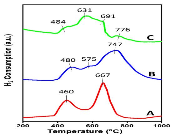
Figure 8.
Temperature-programmed reduction (TPR) profiles of the prepared NiMo/CaTiO3 catalysts calcined at different temperatures: (A) 600 °C, (B) 700 °C, and (C) 800 °C.
Evaluating the effect of different calcination temperature on the yield of MWCNTs shows that there was not much appreciable difference in the carbon yield as the calcination temperature increased from 600 to 800 °C. The carbon yield gradually increased from 43% at 600 °C to 44% at 700 °C and showed a little decline to 42% as the thermal treatment temperature was further increased to 800 °C. The decrease in carbon yield at 800 °C could be attributed to the excessive dominance of the thermally stable NiMoO4 and CaMoO4 species (as observed in the XRD pattern in Figure 7). Although their presence assisted in inhibiting the formation of large NiO particle mass, they also take up the active metal species, which are the bedrock for CNTs nucleation and growth, thereby reducing their availability for nucleation, resulting in low carbon yield [61].
The TEM micrographs of the as-produced carbon are shown in Figure 9. It could be observed that the presented filamentous hollow-core nanostructure indicates the presence of MWCNTs, although a few carbon nanofibers (CNFs) are present. The catalyst calcined at 600 °C showed long MWCNTs with large uniform outer diameter CNTs ranging from 11 to 60 nm and few surface-rugged CNTs. The catalyst calcined at 800 °C produced short structured MWCNTs with an outer diameter in the range of 14–32 nm. The obtained short length MWCNTs could be a result of its large NiO crystallite size, as observed in Table 2. Studies in the literature have reported that increasing the calcination temperature of catalysts results in the loss of their porosity [50,68]. This is true as shown in the BET surface area and pore volume, as presented in Table 1. It is also evident that at high calcination temperature, NiO particles are prone to agglomerate, which could reduce the mobility of active species on the support, resulting in a reduction of carbon yield and/or reduction of the number of reducible NiO present in the bulk catalyst [43]. However, this study reveals that although the interaction of the NiO species could be strong, the good stability of the catalyst material still resulted in the growth of small diameter CNTs.
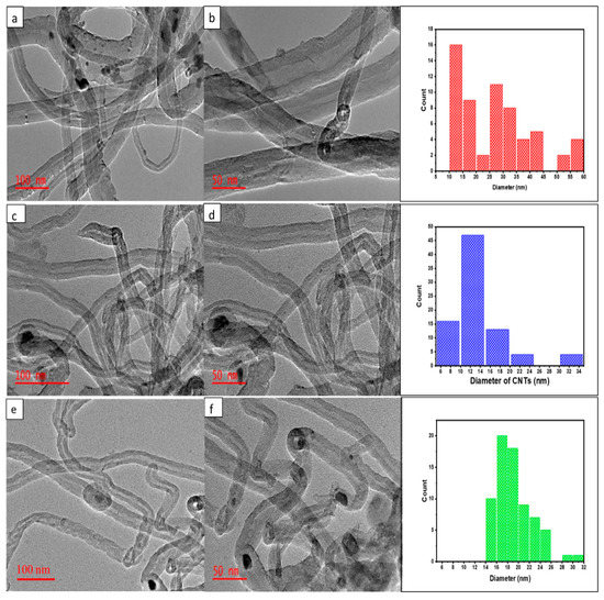
Figure 9.
TEM images and outer diameter distribution of the as-synthesized CNTs over NiMo/CaTiO3 (NMC412) catalysts prepared at different calcination temperatures: (a,b) 600 °C, (c,d) 700 °C, and (e,f) 800 °C.
The Raman spectra of as-grown CNTs deposited on NiMo/CaTiO3 catalyst prepared at various calcination temperatures are shown in Figure 10. The appearance of three major peaks (D-band, G-band, and G’ or 2D-bands) could be seen on the spectrum for each CNT sample. The intensity ratios IG/ID of 1.00, 1.12, and 1.03 were obtained from CNTs deposited over 600 °C, 700 °C, and 800 °C calcined catalysts, respectively. The intensity ratio IG/ID is an indicator of the quality of CNTs [63]. Therefore, the relatively high IG/ID ratio of 1.12 for CNTs obtained over a 700 °C-treated catalyst indicates less defects or amorphous carbon within the graphite layer, unlike CNTs deposited on 600 °C and 800 °C calcined catalysts with a lower IG/ID ratio. Consequently, the 700 °C thermally treated catalyst showed less defective and higher quality and structurally ordered MWCNTs than 600 °C and 800 °C catalysts. This result suggests that CNTs deposited on a 700 °C thermally-treated catalyst had more of an sp2 hybridized in-plane graphitic structure than CNTs obtained on 600 °C and 800 °C calcined catalysts. The result from Raman spectra was in agreement with those of thermogravimetric analysis (TGA) and TEM. This is an indication of the high quality of CNTs obtained over a bimetallic NiMo-supported CaTiO3 catalyst mix, irrespective of their degree of thermal treatment.
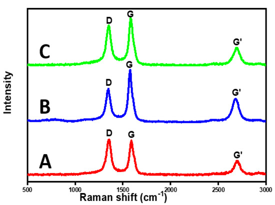
Figure 10.
Raman spectra of as-produced CNTs over NiMo/CaTiO3 catalysts prepared at different calcination temperatures: (A) 600 °C, (B) 700 °C, and (C) 800 °C.
Typically, model CNTs and graphite are reported to oxidize and decompose under O2 and inert environment at temperatures above 500 °C and 600 °C, respectively [70]. For all as-grown CNTs over 600 °C, 700 °C, and 800 °C calcined catalysts, weight loss started above 600 °C and 500 °C under inert and oxidizing environments, as indicated in Figure 11a,b, respectively. Weight losses were calculated to be 76.7%, 83.2%, and 75.0% for all CNTs deposited over 600 °C, 700 °C, and 800 °C calcined catalysts, respectively. However, the catalyst calcined at 600 °C produced the least thermally stable CNTs.
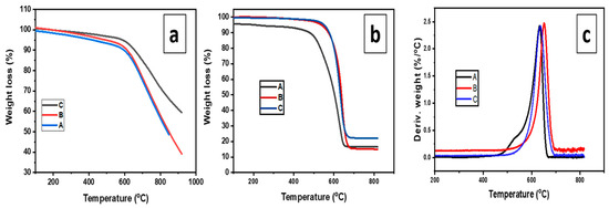
Figure 11.
Thermogravimetric analysis (TGA) and Differential Thermal analysis (DTG) curves of as-produced CNTs deposited over NiMo/CaTiO3 catalyst prepared at different calcination temperatures: A = 600 °C, B = 700 °C, and C = 800 °C: (a) under N2; (b) under O2, and (c) DTG under O2 atmosphere.
3. Materials and Methods
3.1. Materials and Catalyst Preparation
Nickel (II) nitrate hexahydrate, ammonium molybdate tetrahydrate, and calcium carbonate (supplied by Associated Chemical Enterprises (PTY) LTD); titanium (IV) isopropoxide (TTIP) (Sigma-Aldrich, Johannesburg, South Africa), additive-citric acid (supplied by Rochelle Chemicals and Laboratory equipment company, Johannesburg, South Africa); ethanol solvents, and deionized water were used in the synthesis. All supplied chemicals were used without further purification. The sol–gel method was used to prepare bimetallic NiMo/CaTiO3 catalysts with the parent catalyst (metal content) composition Ni–Mo maintained at a molar ratio of 4:1. The support (CaTiO3) content was varied (while still maintaining a Ca/Ti molar ratio at 1:1 in both catalysts), resulting in two catalysts of different support content; NiMo/CaTiO3 (molar ratio 4:1:2) and NiMo/CaTiO3 (molar ratio 4:1:4).
CaO precursor was dissolved in ethanol, and 1.7 M of TTIP was drop-wisely added to the Ca–ethanol solution while vigorously stirred using a magnetic stirrer at 80 °C at a pH = 9.0. The entire mixture was allowed to stir under the same conditions for 5 h. Thereafter, the calculated amount of Ni and Mo salt precursors was dissolved in deionized water, and the mixture added to the Ca–TTIP solution while still vigorously stirred. Again, 4.0 g of citric acid was also added to the mixture until pH = 4.0, and the entire content aged overnight. The resultant gel was oven-dried for 6 h at 100 °C to remove the remaining solvents. The obtained solid chunk was crushed to powder using an agate mortar and calcined in air at 700 °C for 3 h to obtain the fresh catalyst. The final catalysts were denoted as NMC412 and NMC414 for NiMo/CaTiO3 catalysts with molar ratios of 4:1:2 and 4:1:4, respectively.
3.2. Production of CNTs from Waste PP
The waste PP (food package container) used for this work was obtained from the University of Johannesburg refuse deposition/collection center, washed, air-dried, and cut into tiny pieces (1–4 mm) using a Retsch SM 200 (Retsch GmbH, Haan, Germany) jaw crusher. The experimental setup used in the production of CNTs from waste PP was similar to that described elsewhere by Mishra et al. [65] with some modifications. Briefly, a single-stage CVD setup was utilized to grow CNTs from waste PP. The system consisted of a horizontal tubular furnace and a quartz tube reactor (110 cm length and 50 mm I.D.), as well as a gas supplying system with a flow meter and exhaust gas bubbler at the end.
Two sets of experiments were carried out in this study to determine the effect of different catalyst support contents (NMC412 and NMC414) on the yield and quality of CNTs, as well as the influence of different calcination temperatures (600 °C, 700 °C, and 800 °C) on the quality and morphology of CNTs. Typically, 0.5 g of catalyst was packed evenly on a quartz boat situated at the center of the reactor and heated to 700 °C at a ramp rate of 10 °C/min. When the set temperature was achieved, the catalyst was reduced in situ for 20 min under the flow of 5 vol.% H2/95 vol.% Ar gas mixtures at a flow rate of 100 mL/min. At the end of the treatment, the 5 vol.% H2/95 vol.% Ar gas mixture was switched to N2, maintaining the flow at 100 mL/min; then, the ceramic boat housing 1.0 g of waste PP was introduced for the continuous decomposition and growth of carbon nanomaterial at a dwelling time of 30 min, after which the reactor was cooled down overnight in a N2 atmosphere at a flow rate of 100 mL/min. The experiment was repeated to assure the reliability and repeatability of the results. The obtained black material was further purified using mild acid treatment (0.1 M HCl) and subsequently washed with hot and cold DI water until the pH was around 7. The CNT yield was estimated with respect to the mass of feedstock (waste PP) used according to Equation (1) as described by [71]:
where, Mass of CNTs = Mass of carbon deposit before purification–Mass of catalyst used.
3.3. Catalysts and CNTs Characterization
3.3.1. Morphological Analysis
A surface morphological study of catalysts was performed using VEGA 3 TESCAN (TESCAN, Brno, Czech Republic) scanning electron microscope (SEM) operated at 10 kV, which was coupled to an energy-dispersive X-ray spectroscopy (EDXS).
3.3.2. Microstructure Analysis
The morphology of the catalysts and microstructure of deposited carbon as well as the diameters of catalyst metal particles was carried out with a JEM-2100 transmission electron microscope (TEM) instrument (JEOL, Tokyo, Japan) operating at 200 kV. A small amount of sample was dispersed and sonicated in ethanol for 10 min; 2 drops of the blend were dispersed onto carbon-coated copper grid, dried, and photographed.
3.3.3. X-Ray Diffraction
The different crystalline phases present on the surface of NiMo-supported CaTiO3 catalysts of different contents were determined out by X-Ray Diffraction (XRD) using Rigaku Ultima IV X-Ray Diffractometer (RIGAKU Corporation, Tokyo, Japan). The samples were scanned in the 2θ range of 10° to 90° with a step width of 0.01° operating at 40 kV and 30 mA with Cu Kα (λ = 1.54 Å) radiation. XRD data analysis was undertaken using PDXL software.
3.3.4. Surface Area and Pore Volume Measurement
The textural properties of the prepared catalysts were determined by nitrogen physisorption analysis at −196 °C using Micromeritics ASAP 2020 (Micromeritics, Atlanta, GA, USA) surface area and a particle analyzer. During the analysis, 200 mg of catalyst was degassed under vacuum using a Micromeritics flow Prep 060 sample degas system at 300 °C for 3 h. The adsorption isotherm was used to estimate the specific surface area, while the Barrett–Joyner–Halenda (BJH) method was used to estimate the pore volumes of the catalysts.
3.3.5. Temperature-Programmed Reduction (TPR)
The TPR technique was used to study the reduction behavior of the catalysts using a Quantachrome TPR-Win instrument (Quantachrome, Boynton Beach, FL, USA); about 100 mg of the fresh catalyst was dried at 300 °C for 1 h under Ar flow and then cooled to room temperature. Afterwards, 5 vol.% H2/95 vol.% Ar gas mixture with a flow rate of 30 mL/min was passed through the catalyst. The catalyst was heated to 800 °C at a heating rate of 10 °C/min for 2 h. A thermal conductivity detector (TCD) was used to monitor the H2 consumption by the metallic oxide part of the catalyst.
3.3.6. Thermogravimetric Analysis (TGA)
TGA analysis was employed to examine the thermal stability of the as-produced carbon nanomaterial using a HITACHI STA-7200RV thermal analysis system (HITACHI, Tokyo, Japan). The analysis was carried out in two different environments: N2 and air atmosphere. During the analysis, the sample was heated under N2 and synthetic air at a gas flow rate of 20 mL/min with a ramp rate of 10 °C/min from 30 to 900 °C.
3.3.7. Raman Spectroscopy
The purity and graphitization degree of as-produced CNTs were determined using WITec focus innovations Raman spectrometer (WITec Wissenschaftliche Instrumente and Technologie GmbH, Ulm, Germany) operating at a wavelength of 532 nm with Raman shift in the range of 500 to 3000 cm−1.
4. Conclusions
The yield, quality, and morphology of carbon nanotubes (CNTs) obtained from waste PP is greatly influenced by the amount of catalyst support in the catalyst. In this study, bimetallic NiMo-supported CaTiO3 catalysts with excellent stability and superior activity for the synthesis of CNTs from waste PP were successfully synthesized and tested. The strong interaction between metal and support resulted in a higher yield for both catalysts with different supports (CaTiO3) content. This can be attributed to the presence of thermally stable species in the catalysts that inhibited the agglomeration of metal particles resulting in the formation of small metal particles and the resultant high yield and small diameter CNTs. The low CaTiO3 content in the NiMo catalyst (denoted as NMC412) gave the highest CNTs yield and quality. However, increasing the calcination temperature from 600 to 800 °C resulted in a shift in CNTs morphology to a shorter length and larger diameter CNTs at 800 °C and a drop in CNTs yield. The maximum CNTs quality and a yield of 44% was obtained over the NiMo/CaTiO3 catalyst with a molar ratio of 4:1:2 calcined at 700 °C. Therefore, the excellent thermal stability of the NiMo/CaTiO3 catalyst plays a more determining role in the catalytic decomposition of PP toward CNTs growth in a single stage CVD setup. Therefore, this work presents the feasibility of growing CNTs from waste PP using an efficient NiMo/CaTiO3 catalyst in a single-stage CVD method. Thus, it highlights the potential of this approach for the large-scale production of CNTs from wastes.
Supplementary Materials
The following are available online at https://www.mdpi.com/2073-4344/10/9/1030/s1, Table S1: Particle size (nm) distribution of NMC412 catalyst, Table S2: Particle size (nm) distribution of NMC414 catalyst, Table S3: Elemental composition of NMC412 and NMC414 catalysts obtained from EDXS analysis, Table S4: Outer diameter (nm) of CNTs deposited over NMC412 catalyst, Table S5: Outer diameter (nm) distribution of CNTs deposited over NMC414 catalyst, Figure S1: Raman spectra of as-synthesized CNTs over NMC412 and NMC414, Table S6: Outer diameter distribution of CNTs obtained over 600 °C calcined catalyst, Table S7: Outer diameter distribution of CNTs obtained over 700 °C calcined catalyst, Table S8: Outer diameter distribution of CNTs obtained over 800 °C calcined catalyst and Table S9: TGA data of as-deposited CNTs over NiMo/CaTiO3 catalyst calcined at different temperature.
Author Contributions
H.U.M., K.M., and M.O.D. planned and designed the experiments, M.A.M. provided the setup equipment and the reactor system, H.U.M. performed the experimental analysis, K.M. and H.U.M. performed the characterizations, H.U.M. wrote the original draft manuscript, M.O.D., M.A.M. and K.M. revised and edited the manuscript, K.M. and M.O.D. supervised the project. All authors have read and agreed to the published version of the manuscript.
Funding
This work was funded by the University of Johannesburg, South Africa, under the Global Excellence Stature 4.0 (G.E.S. 4.0).
Conflicts of Interest
The authors declare no conflict of interest.
References
- Mubarak, N.M.; Abdullah, E.C.; Jayakumar, N.S.; Sahu, J.N. An overview on methods for the production of carbon nanotubes. J. Ind. Eng. Chem. 2014, 20, 1186–1197. [Google Scholar] [CrossRef]
- Pang, J.; Bachmatiuk, A.; Ibrahim, I.; Fu, L.; Placha, D.; Martynkova, G.S.; Trzebicka, B.; Gemming, T.; Eckert, J.; Rümmeli, M.H. CVD growth of 1D and 2D sp2 carbon nanomaterials. J. Mater. Sci. 2016, 51, 640–667. [Google Scholar] [CrossRef]
- Deng, J.; You, Y.; Sahajwalla, V.; Joshi, R.K. Transforming waste into carbon-based nanomaterials. Carbon 2016, 96, 105–115. [Google Scholar] [CrossRef]
- Borsodi, N.; Szentes, A.; Miskolczi, N.; Wu, C.; Liu, X. Carbon nanotubes synthetized from gaseous products of waste polymer pyrolysis and their application. J. Anal. Appl. Pyrolysis 2016, 120, 304–313. [Google Scholar] [CrossRef]
- Alves, J.O.; Zhuo, C.; Levendis, Y.A.; Tenório, J.A.S. Catalytic conversion of wastes from the bioethanol production into carbon nanomaterials. Appl. Catal. B Environ. 2011, 106, 433–444. [Google Scholar] [CrossRef]
- Moo, J.G.S.; Veksha, A.; Oh, W.-D.; Giannis, A.; Udayanga, W.D.C.; Lin, S.-X.; Ge, L.; Lisak, G. Plastic derived carbon nanotubes for electrocatalytic oxygen reduction reaction: Effects of plastic feedstock and synthesis temperature. Electrochem. Commun. 2019, 101, 11–18. [Google Scholar] [CrossRef]
- Wu, C.; Nahil, M.A.; Miskolczi, N.; Huang, J.; Williams, P.T. Production and application of carbon nanotubes, as a co-product of hydrogen from the pyrolysis-catalytic reforming of waste plastic. Process Saf. Environ. Prot. 2016, 103, 107–114. [Google Scholar] [CrossRef]
- Yardimci, A.I.; Yilmaz, S.; Selamet, Y. The effects of catalyst pretreatment, growth atmosphere and temperature on carbon nanotube synthesis using Co-Mo/MgO catalyst. Diam. Relat. Mater. 2015, 60, 81–86. [Google Scholar] [CrossRef]
- Han, T.; Nag, A.; Mukhopadhyay, S.C.; Xu, Y. Carbon nanotubes and its gas-sensing applications: A review. Sens. Actuators A Phys. 2019, 291, 107–143. [Google Scholar] [CrossRef]
- Shah, K.A.; Tali, B.A. Synthesis of carbon nanotubes by catalytic chemical vapour deposition: A review on carbon sources, catalysts and substrates. Mater. Sci. Semicond. Process. 2016, 41, 67–82. [Google Scholar] [CrossRef]
- Esteves, L.M.; Oliveira, H.A.; Passos, F.B. Carbon nanotubes as catalyst support in chemical vapor deposition reaction: A review. J. Ind. Eng. Chem. 2018, 65, 1–12. [Google Scholar] [CrossRef]
- Gong, J.; Liu, J.; Chen, X.; Jiang, Z.; Wen, X.; Mijowska, E.; Tang, T. Converting real-world mixed waste plastics into porous carbon nanosheets with excellent performance in the adsorption of an organic dye from wastewater. J. Mater. Chem. A 2015, 3, 341–351. [Google Scholar] [CrossRef]
- Shaikjee, A.; Coville, N.J. The role of the hydrocarbon source on the growth of carbon materials. Carbon 2012, 50, 3376–3398. [Google Scholar] [CrossRef]
- Chung, Y.; Jou, S. Carbon nanotubes from catalytic pyrolysis of polypropylene. Mater. Chem. Phys. 2005, 92, 256–259. [Google Scholar] [CrossRef]
- Bajad, G.S.; Tiwari, S.K.; Vijayakumar, R.P. Synthesis and characterization of CNTs using polypropylene waste as precursor. Mater. Sci. Eng. B 2015, 194, 68–77. [Google Scholar] [CrossRef]
- Jiang, Z.; Song, R.; Bi, W.; Lu, J.; Tang, T. Polypropylene as a carbon source for the synthesis of multi-walled carbon nanotubes via catalytic combustion. Carbon 2007, 45, 449–458. [Google Scholar] [CrossRef]
- Yao, D.; Yang, H.; Chen, H.; Williams, P.T. Co-precipitation, impregnation and so-gel preparation of Ni catalysts for pyrolysis-catalytic steam reforming of waste plastics. Appl. Catal. B Environ. 2018, 239, 565–577. [Google Scholar] [CrossRef]
- Wang, J.; Shen, B.; Lan, M.; Kang, D.; Wu, C. Carbon nanotubes (CNTs) production from catalytic pyrolysis of waste plastics: The influence of catalyst and reaction pressure. Catal. Today 2020, 351, 50–57. [Google Scholar] [CrossRef]
- Yao, D.; Wang, C.H. Pyrolysis and in-line catalytic decomposition of polypropylene to carbon nanomaterials and hydrogen over Fe- and Ni-based catalysts. Appl. Energy 2020, 265, 114819. [Google Scholar] [CrossRef]
- Sharuddin, S.D.A.; Abnisa, F.; Daud, W.M.A.W.; Aroua, M.K. A review on pyrolysis of plastic wastes. Energy Convers. Manag. 2016, 115, 308–326. [Google Scholar] [CrossRef]
- Geyer, R.; Jambeck, J.R.; Law, K.L. Production, use, and fate of all plastics ever made. Sci. Adv. 2017, 3, 25–29. [Google Scholar] [CrossRef] [PubMed]
- Li, Y.; Zhang, X.B.; Tao, X.Y.; Xu, J.M.; Huang, W.Z.; Luo, J.H.; Luo, Z.Q.; Li, T.; Liu, F.; Bao, Y.; et al. Mass production of high-quality multi-walled carbon nanotube bundles on a Ni/Mo/MgO catalyst. Carbon 2005, 43, 295–301. [Google Scholar] [CrossRef]
- Signoretto, M.; Menegazzo, F.; Di Michele, A.; Fioriniello, E. Effects of support and synthetic procedure for sol-immobilized Au nanoparticles. Catalysts 2016, 6, 87. [Google Scholar] [CrossRef]
- Doustan, F.; Pasha, M.A. Growth of carbon nanotubes over Fe-Co and Ni-Co catalysts supported on different phases of TiO2 substrate by thermal CVD. Fuller. Nanotub. Carbon Nanostruct. 2016, 24, 25–33. [Google Scholar] [CrossRef]
- Rashid, H.U.; Yu, K.; Umar, M.N.; Anjum, M.N.; Khan, K.; Ahmad, N.; Jan, M.T. Catalyst role in chemical vapor deposition (CVD) process: A review. Rev. Adv. Mater. Sci. 2015, 40, 235–248. [Google Scholar]
- Moisala, A.; Nasibulin, A.G.; Kauppinen, E.I. The role of metal nanoparticles in the catalytic production of single-walled carbon nanotubes—A review. J. Phys. Condens. Matter 2003, 15, S3011–S3035. [Google Scholar] [CrossRef]
- Lobiak, E.V.; Shlyakhova, E.V.; Bulusheva, L.G.; Plyusnin, P.E.; Shubin, Y.V.; Okotrub, A.V. Ni—Mo and Co—Mo alloy nanoparticles for catalytic chemical vapor deposition synthesis of carbon nanotubes. J. Alloys Compd. 2015, 621, 351–356. [Google Scholar] [CrossRef]
- Xu, X.; Huang, S.; Yang, Z.; Zou, C.; Jiang, J.; Shang, Z. Controllable synthesis of carbon nanotubes by changing the Mo content in bimetallic Fe-Mo/MgO catalyst. Mater. Chem. Phys. 2011, 127, 379–384. [Google Scholar] [CrossRef]
- Yeoh, W.M.; Lee, K.Y.; Chai, S.P.; Lee, K.T.; Mohamed, A.R. The role of molybdenum in Co-Mo/MgO for large-scale production of high quality carbon nanotubes. J. Alloys Compd. 2010, 493, 539–543. [Google Scholar] [CrossRef]
- Shen, Y.; Gong, W.; Zheng, B.; Gao, L. Ni—Al bimetallic catalysts for preparation of multiwalled carbon nanotubes from polypropylene: Influence of the ratio of Ni/Al. Appl. Catal. B Environ. 2016, 181, 769–778. [Google Scholar] [CrossRef]
- Yao, D.; Wu, C.; Yang, H.; Zhang, Y.; Nahil, M.A.; Chen, Y.; Williams, P.T.; Chen, H. Co-production of hydrogen and carbon nanotubes from catalytic pyrolysis of waste plastics on Ni-Fe bimetallic catalyst. Energy Convers. Manag. 2017, 148, 692–700. [Google Scholar] [CrossRef]
- Liu, X.; Zhang, Y.; Nahil, M.A.; Williams, P.T.; Wu, C. Development of Ni- and Fe- based catalysts with different metal particle sizes for the production of carbon nanotubes and hydrogen from thermo-chemical conversion of waste plastics. J. Anal. Appl. Pyrolysis 2017, 125, 32–39. [Google Scholar] [CrossRef]
- Sharma, G.; Kumar, D.; Kumar, A.; Al-Muhtaseb, A.H.; Pathania, D.; Naushad, M.; Mola, G.T. Revolution from monometallic to trimetallic nanoparticle composites, various synthesis methods and their applications: A review. Mater. Sci. Eng. C 2017, 71, 1216–1230. [Google Scholar] [CrossRef] [PubMed]
- Munnik, P.; De Jongh, P.E.; De Jong, K.P. Recent developments in the synthesis of supported catalysts. Chem. Rev. 2015, 115, 6687–6718. [Google Scholar] [CrossRef] [PubMed]
- Noda, S.; Hasegawa, K.; Sugime, H.; Kakehi, K.; Zhang, Z.; Maruyama, S.; Yamaguchi, Y. Millimeter-thick single-walled carbon nanotube forests: Hidden role of catalyst support. Jpn. J. Appl. Phys. Part 2 Lett. 2007, 46, 399–401. [Google Scholar] [CrossRef]
- Modekwe, H.U.; Mamo, M.; Moothi, K.; Daramola, M.O. Synthesis of bimetallic NiMo/MgO catalyst for catalytic conversion of waste plastics (polypropylene) to carbon nanotubes (CNTs) via chemical vapour deposition method. Mater. Today Proc. 2020. [Google Scholar] [CrossRef]
- Perego, C.; Villa, P. Chapter 3—Catalyst preparation methods. Catal. Today 1997, 34, 281–305. [Google Scholar] [CrossRef]
- Yang, N.; Li, M.; Patscheider, J.; Youn, S.K.; Park, H.G. A forest of sub-1.5-nm-wide single-walled carbon nanotubes over an engineered alumina support. Sci. Rep. 2017, 7, 46725. [Google Scholar] [CrossRef]
- Ferdous, D.; Bakhshi, N.N.; Dalai, A.K.; Adjaye, J. Synthesis, characterization and performance of NiMo catalysts supported on titania modified alumina for the hydroprocessing of different gas oils derived from Athabasca bitumen. Appl. Catal. B Environ. 2007, 72, 118–128. [Google Scholar] [CrossRef]
- Gonzalez-Cortes, S.L.; Aray, I.; Rodulfo-Baechler, S.M.A.; Lugo, C.A.; Castillo, H.L.D.; Loaiza-Gil, A.; Imbert, F.E.; Figueroa, H.; Pernia, W.; Rodriguez, A.; et al. On the structure and surface properties of NiO/MgO–La2O3 catalyst: Influence of the support composition and preparation method. J. Mater. Sci. 2007, 42, 6532–6540. [Google Scholar] [CrossRef]
- Ashik, U.P.M.; Daud, W.M.A.W.; Hayashi, J. A review on methane transformation to hydrogen and nanocarbon: Relevance of catalyst characteristics and experimental parameters on yield. Renew. Sustain. Energy Rev. 2017, 76, 743–767. [Google Scholar] [CrossRef]
- Awadallah, A.E.; Mostafa, M.S.; Aboul-enein, A.A.; Hanafi, S.A. Hydrogen production via methane decomposition over Al2O3–TiO2 binary oxides supported Ni catalysts: Effect of Ti content on the catalytic efficiency. Fuel 2014, 129, 68–77. [Google Scholar] [CrossRef]
- Wu, C.; Williams, P.T. Investigation of coke formation on Ni-Mg-Al catalyst for hydrogen production from the catalytic steam pyrolysis-gasification of polypropylene. Appl. Catal. B Environ. 2010, 96, 198–207. [Google Scholar] [CrossRef]
- Lanfredi, S.; Storti, F.; Simões, L.P.M.; Djurado, E.; Nobre, M.A.L. Synthesis and structural characterization of calcium titanate by spray pyrolysis method. Mater. Lett. 2017, 201, 148–151. [Google Scholar] [CrossRef]
- Evans, I.R.; Howard, J.A.K.; Sreckovic, T.; Ristic, M.M. Variable temperature in situ X-ray diffraction study of mechanically activated synthesis of calcium titanate, CaTiO3. Mater. Res. Bull. 2003, 38, 1203–1213. [Google Scholar] [CrossRef]
- Mallik, P.K.; Biswal, G.; Patnaik, S.C.; Senapati, S.K. Characterisation of sol-gel synthesis of phase pure CaTiO3 nano powders after drying. IOP Conf. Ser. Mater. Sci. Eng. 2015, 75, 012005. [Google Scholar] [CrossRef]
- Veksha, A.; Giannis, A.; Oh, W.D.; Lisak, G. Catalytic processing of non-condensable pyrolysis gas from plastics: Effects of calcium supports on nickel-catalyzed decomposition of hydrocarbons and HCl sorption. Chem. Eng. Sci. 2018, 189, 311–319. [Google Scholar] [CrossRef]
- Kaneko, E.Y.; Pulcinelli, S.H.; Teixeira, V.; Santilli, C.V. Sol–gel synthesis of titania—Alumina catalyst supports. Appl. Catal. A Gen. 2002, 235, 71–78. [Google Scholar] [CrossRef]
- Bagheri, S.; Julkapli, N.M.; Hamid, S.B.A. Titanium dioxide catalyst support in heterogenous catalysis. Sci. World J. 2014, 2014, 727496. [Google Scholar] [CrossRef]
- Pfaff, G. Synthesis of calcium titanate powders by the sol-gel process. Chem. Mater. 1994, 6, 58–62. [Google Scholar] [CrossRef]
- Gargori, C.; Cerro, S.; Galindo, R.; García, A.; Llusar, M.; Badenes, J.; Monrós, G. New vanadium doped calcium titanate ceramic pigment. Ceram. Int. 2011, 37, 3665–3670. [Google Scholar] [CrossRef]
- Yahya, N.Y.; Ngadi, N.; Lani, N.S.; Ali, M.W. Pilot evaluation of calcium titanate catalyst for biodiesel production from waste cooking oil. Chem. Eng. Trans. 2017, 56, 595–600. [Google Scholar] [CrossRef]
- Baker, E.G.; Summit, N.J. Titanium Dioxide-Calcium Oxide Catalyst for Cracking Hydrocarbons. U.S. Patent 2,886,513, 12 May 1959. [Google Scholar]
- Pudukudy, M.; Yaakob, Z.; Kadier, A.; Takriff, M.S.; Hassan, N.S.M. One-pot sol-gel synthesis of Ni/TiO2 catalysts for methane decomposition into COx free hydrogen and multiwalled carbon nanotubes. Int. J. Hydrogen Energy 2017, 42, 16495–16513. [Google Scholar] [CrossRef]
- Salinas, D.A.; Marchena, C.L.; Pierella, L.B.; Pecchi, G. Catalytic oxidation of 2-(methylthio)-benzothiazole on alkaline earth titanates, ATiO3 (A = Ca, Sr, Ba). Mol. Catal. 2017, 438, 76–85. [Google Scholar] [CrossRef]
- Yao, D.; Zhang, Y.; Williams, P.T.; Yang, H.; Chen, H. Co-production of hydrogen and carbon nanotubes from real-world waste plastics: Influence of catalyst composition and operational parameters. Appl. Catal. B Environ. 2018, 221, 584–597. [Google Scholar] [CrossRef]
- Aboul-Enein, A.A.; Adel-Rahman, H.; Haggar, A.M.; Awadallah, A.E. Simple method for synthesis of carbon nanotubes over Ni-Mo/Al2O3 catalyst via pyrolysis of polyethylene waste using a two-stage process. Fuller. Nanotub. Carbon Nanostruct. 2017, 25, 211–222. [Google Scholar] [CrossRef]
- Ward, D.A.; Ko, E.I. Preparing catalytic materials by the sol-gel method. Ind. Eng. Chem. Res. 1995, 34, 421–433. [Google Scholar] [CrossRef]
- Wang, B.; Yang, Y.; Li, L.-J.; Chen, Y. Effect of different catalyst supports on the (n,m) selective growth of single-walled carbon nanotube from Co–Mo catalyst. J. Mater. Sci. 2009, 44, 3285–3295. [Google Scholar] [CrossRef]
- Zhang, Q.; Yi, L.; Ling, H.; Qian, W.Z.; Luo, G.H.; Fei, W. Synthesis of thin-walled carbon nanotubes from methane by changing the Ni/Mo ratio in a Ni/Mo/MgO catalyst. New Carbon Mater. 2008, 23, 319–325. [Google Scholar] [CrossRef]
- Yeoh, W.M.; Lee, K.Y.; Chai, S.P.; Lee, K.T.; Mohamed, A.R. Effective synthesis of carbon nanotubes via catalytic decomposition of methane: Influence of calcination temperature on metal-support interaction of Co-Mo/MgO catalyst. J. Phys. Chem. Solids 2013, 74, 1553–1559. [Google Scholar] [CrossRef]
- Zhuo, C.; Hall, B.; Richter, H.; Levendis, Y. Synthesis of carbon nanotubes by sequential pyrolysis and combustion of polyethylene. Carbon 2010, 48, 4024–4034. [Google Scholar] [CrossRef]
- Aboul-Enein, A.A.; Awadallah, A.E.; Abdel-Rahman, A.A.-H.; Haggar, A.M. Synthesis of multi-walled carbon nanotubes via pyrolysis of plastic waste using a two-stage process. Fuller. Nanotub. Carbon Nanostruct. 2018, 26, 443–450. [Google Scholar] [CrossRef]
- Dikio, E.D.; Shooto, N.D.; Thema, F.T.; Farah, A.M. Raman and TGA study of carbon nanotubes synthesized over Mo/Fe catalyst on aluminium oxide, calcium carbonate and magnesium oxide support. Chem. Sci. Trans. 2013, 2, 1160–1173. [Google Scholar] [CrossRef][Green Version]
- Mishra, N.; Das, G.; Ansaldo, A.; Genovese, A.; Malerba, M.; Povia, M.; Ricci, D.; Fabrizio, E.D.; Zitti, E.D.; Sharon, M.; et al. Pyrolysis of waste polypropylene for the synthesis of carbon nanotubes. J. Anal. Appl. Pyrolysis 2012, 94, 91–98. [Google Scholar] [CrossRef]
- Bajad, G.; Jain, R.; Harhare, W.; Vijayakumar, R.P.; Bose, S. Synthesis of fuel oil and carbon nanotubes in an autoclave using plastic waste as precursor. Mater. Manuf. Process. 2017, 32, 495–500. [Google Scholar] [CrossRef]
- Liu, H.; Yin, C.; Liu, B.; Li, X.; Li, Y.; Chai, Y.; Liu, C. Effect of calcination temperature of unsupported NiMo catalysts on the hydrodesulfurization of dibenzothiophene. Energy Fuels 2014, 28, 2429–2436. [Google Scholar] [CrossRef]
- Acomb, J.C.; Wu, C.; Williams, P.T. Control of steam input to the pyrolysis-gasification of waste plastics for improved production of hydrogen or carbon nanotubes. Appl. Catal. B Environ. 2014, 147, 571–584. [Google Scholar] [CrossRef]
- Fan, X.; Liu, D.; Zhao, Z.; Li, J.; Liu, J. Influence of Ni/Mo ratio on the structure-performance of ordered mesoporous Ni-Mo-O catalysts for oxidative dehydrogenation of propane. Catal. Today 2020, 339, 67–78. [Google Scholar] [CrossRef]
- Chen, X.; Wang, H.; He, J. Synthesis of carbon nanotubes and nanospheres with controlled morphology using different catalyst precursors. Nanotechnol. Rev. 2008, 19, 325607. [Google Scholar] [CrossRef]
- Zhuo, C.; Levendis, Y.A. Upcycling Waste Plastics into Carbon Nanomaterials: A Review. J. Appl. Polym. Sci. 2014, 131, 39931. [Google Scholar] [CrossRef]


© 2020 by the authors. Licensee MDPI, Basel, Switzerland. This article is an open access article distributed under the terms and conditions of the Creative Commons Attribution (CC BY) license (http://creativecommons.org/licenses/by/4.0/).