Abstract
The purification of diesel exhaust gas is of great importance to prevent the atmospheric emission of major pollutants such as diesel particulate matter and nitrogen oxides and meet the environmental regulations. The atmospheric-pressure plasma is attracting increasing interest and is a promising after-treatment technology for purifying diesel emission at low temperatures. However, when compared with the numerous publications on nitrogen oxides reduction by non-thermal plasma, using non-thermal plasma to particulate matter treatment have relatively limited. This work provides a comprehensive review of the plasma applications for diesel particulate matter treatment, including self-regenerating diesel particulate filter, diesel particulate matter removal, and simultaneous removal of diesel particulate matter and nitrogen oxides. The treatment of particulate matter from both simulated particulate matter sources and actual diesel engines also discussed in this comprehensive review. The challenge to this technology is limited energy consumption for plasma, which should be less than 5% (~30 J/L) of the overall fuel consumption. Until now, the atmospheric-pressure plasma has been no commercial implementation in diesel exhaust gas treatment, so more research is needed to be done in this field.
1. Introduction
Environmental impacts are the primary concern of diesel exhaust gas (DEG) that contains hazardous materials that are harmful to the environment as well as human health. Table 1 presents the components and their concentrations in typical DEG [1]. Regarding sustainable development and environmental protection, stricter legislation has been instituted to minimize contaminants, such as a significant decrease in the number of emission criteria components in the European Union from Euro 1 to Euro 6 [2]. To sustain the use of diesel engines and meet the newest emission standards, an enhancement in the treatment of DEGs is needed. Thus, research into the treatment of DEGs is still an essential and worthy topic.

Table 1.
Typical composition of diesel exhaust gas [1].
The elimination of diesel particulate matter (DPM) is challenging in that the particulate matter (PM) emission less than 0.005 g/km is a requirement in Euro 6 emission standards for passenger cars. A formation of DPM is caused by incomplete combustion of diesel fuel, which condenses into small solid particles. The DPM is complex components comprised of carbon (soot), unburnt hydrocarbon, sulfate, ash, etc. [3,4]. However, diesel exhaust particles can be classified into two groups: volatile (soluble fraction) and non-volatile substances (insoluble fraction) [5,6,7]. The soluble materials have three main components, namely, a soluble organic fraction (SOF), a sulfur fraction (SF), and nitrate. The SOF of the DPM depends on the type of diesel engines and its operation conditions; in some cases, SOF accounts for 80% of DPM [5]. The SOF consists of polycyclic aromatic compounds (PACs) [6]. The SF is oxidized to form primarily SO2 and partially sulfate, while nitrate fractions are mainly nitric acid (HNO3) form. These compounds are present in DPM due to the adsorption of PACs and other compounds on carbon particle surfaces. At high DEG temperatures, they are in the gas phase; however, they condense into a solid phase during the exhausted gas being emitted to the atmosphere [7].
As aforementioned, DPM consists mainly of soot and hydrocarbons, implying that filtration and decomposition of DPM are not easy. The process requires harsh conditions such as high operating temperature or high input energy. In recent years, various conventional technologies have been developed, including diesel particulate filters (DPF) [8,9,10,11,12,13,14], diesel oxidation catalyst (DOC) [15,16,17], selective catalytic reduction (SCR), and particle oxidation catalysts (POC) [18,19,20]. Though they present certain advantages, the above technologies have several limitations mentioned in the next section. One of them is the high-temperature operation. Nonthermal plasma, specifically atmospheric pressure plasma, has been recognized as a promising low-temperature technology for DEG treatment with outstanding benefits [21,22,23]. In this regard, active research for practical implementations of this technology is urgently needed to meet stringent diesel engine emission standards ever.
In this review, the challenge and opportunity of plasma in the removal of DPM have been discussed. Firstly, the fundamentals of DPM treatment are described with respect to conventional technologies and nonthermal plasma (atmospheric-pressure plasma). This presents that atmospheric-pressure plasma is a promising method for DEG treatment in the low-temperature ranges as in typical DEGs (150–350 °C). Thus, a survey on the treatment of DPM using atmospheric pressure plasma was made for simulated and actual DEGs. Many researchers have used simulated DEG instead of actual DEG in their studies because the composition is complicated and largely depends on operating modes. A review in the literature indicates that DPM removal with atmospheric pressure plasma is an effective method and can be carried out at low temperatures. After a thorough investigation of the reactor configurations, the authors found that there has been no commercial implementation of plasma in DEG treatment. Indeed, the generation of atmospheric-pressure plasma in a commercial plasma applications is difficult due to its size and physical structure.
2. Methods for Filtration and Destruction of DPM
The mechanism and disadvantage of two conventional approaches, like DPF and DOC, to eliminate PM are discussed in this section. As well, the method for processing PM by plasma technology at low temperatures is addressed. Plasma technology can be a useful solution to get over the limitations of conventional methods; however, there is a problem for large-scale plasma applications.
2.1. Conventional Technologies for Controlling Diesel Particulates
DPF is one of the most popular and effective methods for trapping PM particles [11], which have been used since the 1970s [8]. The physical technique of DPF is to trap and filter particles through its micro-pores, meso-pores, and macro-pores [4]. The filtration performance of DPFs depends on the filter shape and material properties. DPF is generally a solid cylinder shape and adopts cordierite, silicon carbide (SiC), active carbon fiber [9,14], and ceramic material. Figure 1 illustrates the general principle of DPF’s particle trap when the gas flows through the porous channels [24].
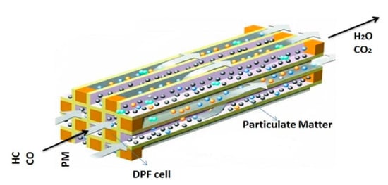
Figure 1.
Principle of DPF for trapping particulate matters. Reprinted from Ref. [24], with the permission from Elsevier.
Although DPF has many advantages such as high trapping efficiency and economic value [11,12], its widespread use is hampered by some drawbacks. For instance, DPFs need to be frequently regenerated in time to maintain working efficiency under high-temperature conditions. A simple explanation can be given as follows: PM deposition is a natural phenomenon when the temperature of DEG is lower than 300 °C [10]. The PM deposition could cause suffocation of DPF and therefore requires regeneration. The temperature required to regenerate DPF is about 600 °C [13,25], but this indirectly increases fuel consumption, affecting the economic viability. Other than honeycomb-structured DPFs that are made of cordierite and SiC material, Du et al. [14] introduced an alternative DPF made of gear-shaped wood fiber filter (WFF), as shown in Figure 2. This provides filtration efficiency of about 85%, and the life span of WFF more than 90 h using. Notably, it has a low cost and simple manufacturing process. However, the temperature factor affecting PM deposition was not mentioned in this study, implying that self-regeneration at high temperatures still remains challenging for practical applications.
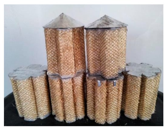
Figure 2.
The gear-shaped wood fiber filter. Reprinted from Ref. [14], with the permission from the authors.
Besides the thermal regeneration of DPF, several studies showed the possibility of using microwaves for the same purpose [26,27]. Catalytic diesel particulate filter (CDPF) systems with good contact between soot and active areas have also been studied elsewhere, in which soot is abated by oxidation reactions. Commonly used catalysts in these studies include mixed metal oxides such as CuFe2O4 [28], CoAlO, NiAlO, CuAlO, etc. [29,30], a precious gold metal such as Pt-Pd, and rare earth metal oxides such as LaCoO3 and CoCeO [31,32,33]. The presence of catalysts in DPF enables one to simultaneously remove soot and NOx by the reaction between them, leading to the formation of CO2 and N2, which are non-toxic. The DPF regeneration by microwaves and the CDPFs are still tricky from the practical application viewpoint, because of low catalytic activity at low temperatures, catalyst (noble metal) cost, troublesome incorporation of a microwave system with DPF, and non-uniformity of microwave heating.
The diesel oxidation catalyst (DOC) was first introduced in the 1970s, which can decrease in the SOF as well as DPM through oxidizing reactions.
SOF + O2 → CO2 + H2O
C + O2 → CO2
CO + O2 → CO2
HC + O2 → CO2 + H2O
Wade et al. [15] made use of the DOC system on heavy-duty trucks in 1994 to decrease the total PM emission by converting pollutants, including a liquid portion of DPM, CO, and hydrocarbons to CO2 and H2O, as shown in Figure 3. In 1998, Prasad and coworkers [16] applied DOC to PM emission reduction; however, it exhibited a quite low efficiency of about 20–40%. It was shown that the use of Pt-Pd as a catalyst in DOC could remove all the SOF, while the emission of PM decreased by 25–50% [4]. In other words, the DOC only reduces up to half of DPM. Moreover, the catalyst deactivated by the metal sulfate formation at high temperatures on the metal surface is a great concern in this method [16,17].
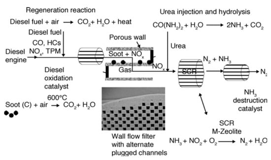
Figure 3.
Diesel emission for a truck. Reprinted from Ref. [15], with permission from Elsevier.
2.2. Fundamentals of DPM Treatment by Nonthermal Plasma Technology
Plasma is a term in physics and engineering; it describes an electrically conductive term of ionized gas and includes electrons, ions, radicals, and neutral gases [34]. Plasma is more than 99% of matter in the cosmos. By delivering energy into a discharge zone which could be supplied through thermal or electrical sources, plasma can be produced. The energy is used in neutral gases to create ions and an excited state. Plasma grouping can be classified in various groups, based on the temperature and density of electrons, i.e., nonthermal plasma (NTP) and thermal plasma. The NTP is characterized by high electron temperature (Te) of a few thousand K and low ion (Ti) and neutral gas temperatures (Tg) of a few hundred K [34,35]. Therefore, this is also called non-equilibrium plasma. The NTP produces energetic electrons, excited molecules, and radical species at near room temperatures, which are all highly reactive [36]. The NTP has widely been studied for gas treatment, for instance, the removal of volatile organic compounds [37,38]. The NTP for DEG treatment works under atmospheric pressure and is a kind of atmospheric-pressure plasma. Highlights of atmospheric-pressure plasma can oxidize PM at low temperatures (~200 °C) [39], exhibiting rapid reaction rate resulting in complete decomposition and less secondary pollution at a moderate capital cost [1,40,41]. Atmospheric-pressure plasma can be generated by various methods, namely, electron beam [21,42,43], corona discharge [34,44,45], dielectric barrier discharge (DBD) [46,47], and surface discharge [48,49,50].
At present, there is much controversy over the energy efficiency of exhaust treatment by the NTP, since the efficiency is bound to be different when applied in different conditions (e.g., operating conditions of plasma, gas compositions, reactor structures, power sources, etc.), and as well the energy efficiency is defined differently for each study [1]. Among the atmospheric-pressure plasmas, the corona discharge and DBD have been more widely used for DPM treatment than the others. The schematic diagrams of the DBD and corona discharge reactor are shown in Figure 4. The DBD reactor has at least one dielectric layer between electrodes, which prevents arcing and enables stable plasma generation. The dielectric material is electrical insulators such as alumina, quartz, glass, and ceramic. Besides, polymer and thin enamel coating layer can also act as a dielectric barrier. Just like DBD, surface discharge (also known as silent discharge) reactor has a dielectric material between the electrode. When an AC high voltage is applied across the electrodes, surface discharge forms on and over the dielectric surface, as shown in Figure 4c. As in Figure 4d, instead of AC, a pulsed voltage with a narrow width can be used to create DBD plasma. Meanwhile, corona discharge plasma is generated between the two electrodes, for instance, concentric wire-to-cylinder, wire-to-plane, plane-to-plane, and meshes-to-meshes. The discharge starts from the points or sharp edges of one of the electrodes and then propagates towards the counter electrode. Different from the atmospheric-pressure DBD with a narrow gap of a few mm, the corona discharge is generated well even when the electrode spacing is wide, depending on the magnitude of voltage, which suggests that it is more suitable for large-scale applications. Moreover, one of the outstanding features of corona discharge, when created by short-pulsed voltage, is the improvement in the energy efficiency, which is because the energy is primarily used to accelerate electrons and is hardly used to move ions [51].
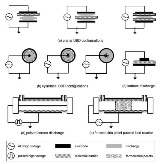
Figure 4.
Several configurations of NTP reactors. Reprinted from Ref. [52], with permission from Elsevier.
The DPM cannot be burned on its own because the temperature of DEG is far below the auto-ignition temperature. Otto et al. [53] reported that the temperature of 350 °C or less might be sufficient to trigger catalytic oxidation, and the required temperature to ensure PM combustion is about 460 °C; however, the catalytic removal of PM does not exceed 50%. Stanmore et al. [54] pointed out that at 600 °C, PM can be ignited itself without any catalyst. In comparison, the NTP can decompose PM at lower temperatures. Nguyen et al. [2] showed that a polycyclic aromatic hydrocarbon, i.e., naphthalene as a simulant for PM, can successfully be decomposed at temperatures as from 200 °C by the combination of plasma with Ag/alumina catalyst, as shown in Figure 5.
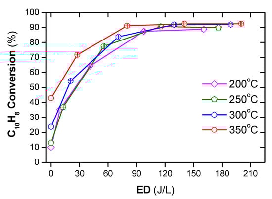
Figure 5.
Conversion of naphthalene under temperature from 200 to 350 °C under various ED (energy density) (total flow rate of 2 L/min including: 48 ppm naphthalene, 300 ppm NO, 3.7% H2O, 10% O2, and N2 as balance). Reprinted from Ref. [2], 2019, MDPI.
3. Mechanism Atmospheric Pressure Plasma for DPM Treatment
The strong oxidation capability of plasma is because it consists of many reactive species such as energetic electrons (e), radicals, ions, ozone and excited molecules (M), which makes it possible to oxidize PM at low temperatures (Figure 6). Previous studies have shown that O radical and O3 react effectively with carbon particulates, unburned hydrocarbon (HC) and SOF to facilitate PM oxidation as summarized below [55,56,57,58,59].
O• + HC + e/M → RO2, RO, •OH +…+ e/M
O3 + SOF + e/M → CO (CO2) + O2 + H2O + e/M
O3 + HC + e/M → H2O + CO2 + e/M
C + O• + e/M → CO + e/M
C + 2O• + e/M → CO2 + e/M
C + O3 + e/M → CO + O2 + e/M
C + 2O3 + e/M → CO2 + 2O2 + e/M
C + O3 + e/M → CO2 + ½ O2 + e/M
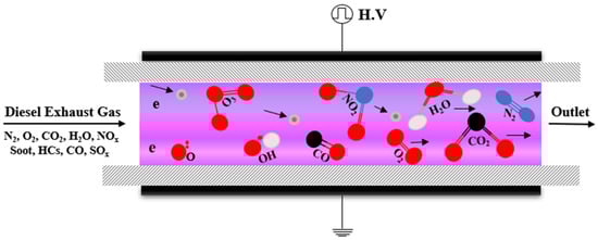
Figure 6.
Mechanism atmospheric pressure plasma for Diesel particulate matter treatment.
The oxidation of NO to NO2 promotes the decomposition of PM accumulated in DPF as follows [60,61,62,63]:
C + 2NO2 + e/M → CO2 + 2NO + e/M
C + NO2 + e/M → CO + NO + e/M
2C + 2NO2 + e/M → 2CO2 + N2 + e/M
Besides, OH radical also plays a significant role in PM oxidation according to the following reactions [64]:
C + 2•OH + e/M → CO2 + 2H + e/M
C + •OH + e/M → CO + H + e/M
CO + •OH + e/M → CO2 + H + e/M
Plasma process depends on several factors, including reactor configuration, packed catalyst, discharge mode, and polarity, amplitude and frequency of voltage. Therefore, the evaluation and comparison of plasma systems for DPM treatment are open to argument. Up to date, there is no general criterion established for the comparison of plasma systems. Several criteria such as selectivity towards COx (CO and CO2) [65,66,67], the pressure drop ∆P [67], the mass decline of PM [68], and the amount of PM removal per energy consumption (g/kWh) [69,70,71] can be used to make a comparison. The efficiency of PM removal (ER), the energy efficiency (EE), and energy density (ED) are calculated by Equations (1)–(3) below
For the consistency of comparison, the gas flow can be based on atmospheric pressure and temperature of 25 °C.
4. Literature Survey on DPM Treatment with Atmospheric Pressure Plasma
The previous studies on the application of plasma to DPM can be classified into three groups: DPF regeneration, direct DPF removal, and simultaneously removal of DPM and NOx. In this review, both simulated PM and real PM in DEG are discussed. The use of the pure gas mixture to simulate DEG is advantageous in identifying reaction intermediates and elucidating the reaction pathways; however, there is essentially a discrepancy between simulated and actual DEG. The components of actual DEG are much more complicated than the simulated one. Furthermore, the composition and the PM content are changeable according to the engine operating conditions. For this reaction, PM treatment efficiency obtained with the actual DEG is often lower than that with the simulated one. This section deals with PM removal from simulated and actual DEG. Table A1 and Table A2 in the Appendix A presents a summary of several noteworthy studies on PM treatment for simulated and actual DEG.
4.1. DPM Removal with Simulated PM Sources
4.1.1. Diesel Particulate Filter Self-Regenerating
DPF has been used widely and the most effective method for reducing PMs in automobile applications [72,73,74,75]. However, owing to the DPM accumulation on the filter walls of the DPF, the blockage DPF frequently occurs. Consequently, the regeneration of DPF by a thermal process (conventional method) is used, such as a continuous regeneration trap (CRT) and catalyzed soot filter (CSF) [75,76]. However, as the aforementioned discussion, DPF regeneration at high temperatures is a disadvantage. Meanwhile, the NTP promotes O3 formation, oxidation of NO to NO2, and the reactive chemical cocktails; they react and convert PM at lower temperature range. Thus, several studies were carried out to regenerate DPF with NTP [59,67,68,77,78,79].
Indirect NTP for DPF regeneration can be considered an effective method. In this technique, the outlet of the plasma source such as O2, air, or NOx is fed through the DPF. Figure 7 shows a schematic of an indirect NTP for DPF regeneration. Shi et al. [80] used O2 plasma to the regeneration of DPF without catalyst under various low-temperature range. The first step includes the formation of O3 and O radicals in the plasma discharge zone, which can be formed by the following reactions (R19)–(R21). In the second step, PM can be decomposed through reaction with O3 and O radical as following reactions (R5)–(R12). The result shows that with the low-temperature of 80 °C, the DPF completely regenerated after 2 h without any catalyst use.
O• + O2 + e/M → O3 + e/M
Figure 7.
Schematic of DPF regeneration system with DBD reactor injection. Reprinted from Ref. [81], with permission from Elsevier.
Effect of various O2 flow rate (3–10 L/min) on the DPF regeneration using indirect O2 plasma in a DBD reactor was examined by Pu et al. [81]; the schematic is shown in Figure 7. The temperature of DPF regeneration was also fixed at 80 °C. The O2 plasma in a DBD was driven by the high AC voltage of 17.5 kV with a high frequency of 8.3 kHz. The result indicated that O3 productivity increased from 83 to 102 g/kWh with O2 flow rate from 7 to 10 L/min, and it slightly changed for the O2 flow rate in the range 10 to 15 L/min. The O3 source by the O2 plasma introduced to DPF regeneration presented that DPM was oxidized to CO and CO2 at the low temperature. As a result, the highest mass of deposit removal was 12.5 g after 3 h regeneration with the 10 L/min O2 plasma at ED of 1.674 kJ/L, equilibrium energy consumption of 0.837 kWh and EE of 14.93 g (PM)/kWh.
For the case of NOx, it incinerated the carbon soot that was accumulated inside the DPF by oxidizing soot to form CO and CO2. Kim et al. [67] investigated the role of NO2 on the soot oxidation on the DPF under the temperature range from 230 to 350 °C. The result indicated that pure NO2 feed could regenerate DPF when operating temperatures were above 250 °C. Also, at the same temperature, NO2 is more effective than O2 for oxidizing the carbon soot. Instead of pure NO2 feed, the soot oxidation occurred at low temperatures, about 230 °C, for the gas treated by plasma (the feed gas consisted of NO, O2, and hydrocarbon). Both pure NO2 or the gas treated by plasma cases, the soot removal efficiency increased toward the operating temperature. However, the plasma gas obtained higher efficiency than pure NO2 feed at the same temperature. The result could be explained by the presence of partially oxidized products in the treated plasma gas that can oxidize carbon at this temperature; consequently, improved soot removal even at low operating temperatures. Individually, the pressure drop (∆P) of the DPF with pretreating the feed gas by plasma decreased significantly at an operating temperature from 230 to 300 °C; the range of temperature is close to the desired temperature to reproduce DPF. Furthermore, this study has been obtained based on simulated diesel exhaust. Therefore, the result of this technique in actual working conditions might be different due to the absence of a large water amount in the simulated feed gas for both cases.
Later, Okubo and co-workers [82] studied the regeneration of the DPF using a barrier-type pulse corona reactor without using any catalyst. The discharge power was 2 W with an applied voltage (peak) of 45 kV at a 210 Hz frequency. The test gas fixed at 3 L/min, was a mixture of 348 ppm NOx (316 ppm NO and 32 ppm NO2) with dry air. Soot was accumulated on the cordierite DPF by an automobile diesel engine operating at medium load mode within 2 h; as a result, the carbon soot per DPF volume was 2.1 g/L. The plasma discharge with 40 J/L oxidized 70% of NO to the NO2, conversion at room temperature, in the plasma stage. In the following stage, the gas outlet from the plasma reactor was passed through the cordierite DPF, the temperature kept constant at 250 °C, for 8 h during the DPF regeneration. As a result, the efficiency of soot removal was approximately 75% at the low temperature. The active DPF regeneration at low temperature may be coming from NO2 and other active oxygen species by the plasma; they are introduced to DPF, and oxidation of carbon soot occurs through (R13)–(R15) reactions. However, the energy consumption for plasma oxidized NO to NO2 stage was 40 J/L, and the duration of the DPF regeneration process (8 h) is four times the loading soot on the DPF (2 h).
Okubo et al. [68] also carried out soot decomposition on DPF incinerated at 300 °C by the indirect or remote plasma method. The plasma discharge was generated by a barrier-type needle-to-plate NTP reactor, and the gas outlet of air plasma was mixed with the exhaust gas. Consequently, about 91% NO in the feed was oxidized to NO2 and then fed through DPF. The result confirmed that DPF regeneration is possible at a low temperature of 300 °C by the injected NO2. Approximately 97% of PM loading on the DPF was incinerated by 4.6 h of the NO2 injection. The energy consumption was 78 J/L for plasma indirect NO oxidization. The author also evaluated the possibility of the technical to actual diesel engines (3-L-class automobile diesel engines). Herein, to target about 3% of the electrical power cost [83], the energy consumption for the plasma step at 78 J/L, in this experiment, needs a reduction to 10 J/L, which can be acceptable in terms of putting research into practical applications. Thus, the technology is promising DPF regeneration at low temperatures and also holds the potential to reduce energy consumption to meet the requirement for practical application.
4.1.2. Removal of Simulated DPM
Yao et al. [65] investigated the oxidation of activated carbon and methane by a corona discharge generated with a point to mesh and DBD, respectively. Activated carbon and methane simulated two PM components for DEG. The plasma was driven with a high-frequency pulse power supply. The results indicate that the oxidation ability of activated carbon was lower than methane with an oxidized rate of 4–10 g-CH4/kWh and 4–40 g-CH4/kWh for activated carbon and methane, respectively. The activated carbon was 1–150 µm in size, which is larger than the diesel PM size (0.1–0.2 µm). Consequently, the PM oxidation from real diesel with a plasma source would be higher than activated carbon. In both cases of oxidation, the selectivity of CO and CO2 products is foremost with a higher selectivity of 90%. The result also proposed power consumption of approximately 0.15 kW is enough to oxidize PM from actual diesel with a velocity of 0.1 g/min.
The removal of simulated diesel exhaust particles, black carbon particulates with an average size of 30 nm, was investigated in a DBD reactor [84]. The influence of oxygen on the PM removal was examined with the N2:O2 ratio of 8:2, 9:1, and 10:0, respectively. The results indicated that PM was removed by both active species of oxygen and nitrogen produced by the plasma. Specifically, with a plasma discharge of 70–120 J/L (7–12 W; flow rate of 6 L/min), approximately 80% of the PM in the feed was eliminated with the mixture ratios. Interestingly, with only N2 as the feed gas (N2:O2 = 10:0), the efficiency of PM removal remained. However, CO2 formation, by oxidization of carbon black, was observed only with the presence of O2 in the feed gas. This suggested that the formation of nitrogen species by plasma could increase the removal of PM. The removal of PM from the actual diesel engine was also carried out under normal load, idling load, and high load with discharge power of 0 W, 100 W, 200 W, or 300 W. The average PM removal obtained was only 43%, except for the idling load mode at 100 W, which is much lower than the simulated DEG removal at 80%. The authors explained the reason for the low-efficiency removal of DEG to be a high flow rate along with a large amount of PM in the DEG compared to the simulated exhaust gas, indicating that the removal of PM from the DEG is a significant challenge in practical applications.
4.1.3. Simultaneous Removal of DPM and NOx in Simulated DEG
In the treatment of DEG, the simultaneous reduction of NOx and DPM gives an advantage, i.e., the reaction between DPM and NOx leads to the NOx reduction and CO2 formation. As discussed above in Section 4.1.1, the reaction rate between DPM and NO2 is higher than that of NO. Unfortunately, NO is a major form of NOx in DEG, and the reactions between NOx and DPM occurs with a low reaction rate at low temperatures. Thanks to advanced plasma, which is characterized by oxidizing NO to NO2 and enhanced reaction between DPM and NOx at low temperatures. Besides, the gas emission during the regular operation of the diesel engine was rich in O2, around 10%, as shown in Table 1. Therefore, the use of a catalyst absorber of NOx under lean periods (rich O2) promotes an increase in the simultaneous reduction of NOx in rich periods (poor O2) [59].
Okubo et al. [45] investigated the simultaneous reduction of PM and NOx using a non-thermal plasma reactor coupled with Ag/γ-Al2O3 pellets (diameter of 2–4 mm); simulated PM is carbon deposited on the pellets. A pulse high-voltage source induced the plasma catalytic reaction under O2 lean conditions. The result indicated the reduction of NOx was carried out with N radicals, whereas, oxidization of carbon was performed by NOx, O radicals, and O3 species at an operating temperature of 120 °C. Notably, the PM oxidization increased toward the concentration of O2 but subsequently reduced the NOx concentration. Specifically, the maximum energy efficiency of 0.92 g(C)/kWh was obtained for the simulated PM removal at an O2 concentration of 2%. In the case of NOx reduction, the energy efficiency was 14.2 g (NO2)/kWh under the absence of O2. Compared to plasma alone, the energy efficiency of NOx removal was significantly increased by the use of a catalyst, with a maximum increase of 47% under the 2% O2 concentration. The authors also compared the packaging between Ag/γ-Al2O3 and BaTiO3 for PM and NOx elimination. The packaged Ag/γ-Al2O3 provided a high PM removal but a low NOx removal compared to the packaged BaTiO3.
In another case with DPF, Tran et al. [60,85,86] created a DBD in a honeycomb structure, which consisted of the pre-reactor (coaxial DBD) conjugated with the main reactor (honeycomb discharge in a DPF), as shown in Figure 8. Specifically, the discharge zone of the pre-reactor was created by a steel needle of 1.8 mm diameter located at center Pyrex glass cylinder (ID: 36 mm; OD: 50 mm; length: 120 mm) as high voltage electrode, and stainless-steel foil (105 mm in length) wrapped the cylinder as ground electrode surrounding. The honeycomb discharge was carried out with a bunch of nine steel wires (0.6 mm in diameter) inside honeycomb cordierite holes (OD of honeycomb: 35.5 mm; square hole: 1.5 × 1.5 mm) acting as a high voltage electrode, while the second stainless steel foil, 40 mm in length, covered another cylinder as a ground electrode. The honeycomb played a PM filter as well as a dielectric layer along with the main cylinder. The plasma source has been used to treat DEG at low temperature (surrounding temperature without heating equipment); the presence of PM conjugated with the plasma has improved the NOx removal at low-temperature ranges [86].
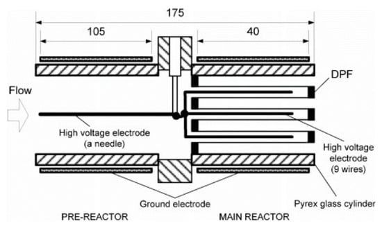
Figure 8.
Dielectric barrier discharge reactor with honeycomb. Reprinted from Ref. [86], with permission from Taylor & Francis Ltd.
A DBD plasma discharge coupled with Ag/α-Al2O3 catalyst was employed for the simultaneous removal of NOx and soot simulant (naphthalene) in Figure 9 [2]. In which, the simulated DEG consisted of 300 ppm NO, 265 ppm n-heptane, 48 ppm naphthalene, 10% O2, 3.7% H2O, and N2 balance. The simultaneous removal of PM and NOx was carried out under the range of operating temperatures from 200 to 350 °C, along with ED from 0 to 210 J/L. The results showed that, under the presence of plasma, removal of PM and NOx occurred at low temperatures. Interestingly, the simulated PM played as a reducing agent for NOx reduction under assisted plasma at low temperature; however, the NOx removal was lower, 10–20%, with the absence of n-Heptane, simulated HC, in the DEG. The high-efficiency soot simulant, as well as NOx and HC, removal of 90% at a temperature of 350 °C and the ED at least 90 J/L; the EE for NOx and soot simulant removal was 6.18 g(N)/kWh and 8.48 g/kWh for C in naphthalene, respectively.
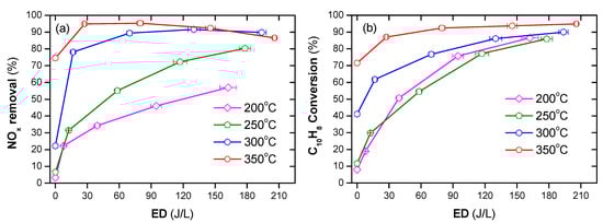
Figure 9.
A plasma-catalyst process enhanced removal of NOx (a) and soot simulant (b) under the temperature from 200 °C to 350 °C with an ED from 0 to 210 J/L. It adapted from Ref. [2].
4.2. DPM Removal from Diesel Engines
4.2.1. Regeneration of Diesel Particulate Filter
DPF regeneration by injecting O3 was reported in the ref. [59]. The O3 was generated by a surface discharge ozonizer of 10 L/min oxygen and the gas outlet connected with the pipe of the DEG. A small diesel engine (J106-STD, 4 cycles, two cylinders, displacement volume 0.479 L) supplied the DEG. Simultaneous reduction of NOx was also carried out at downstream using another plasma reactor, packed-bed DBD with two stages: the first stage was a 6-cm length of zeolite pellets and a 20-cm length of glass pellets for the second stage. Using O2 plasma injection, the regeneration of DPF was efficient at low temperatures (245 °C) with excellent PM removal EE from the DEG at 6.6 g/kWh. In the case of NOx removal, the energy consumption was 16 g (NO2)/kWh. With these energy efficiencies, the post-gas treatment is adequate with the 2009 legislation for diesel automobiles in Japan. However, with inhomogeneous plasma power supplies such as AC power for the generation of ozone and pulse power for the NOx removal, this is hindered in practical applications. From the same practical point of view, we are also concerned with the capable application of the long-packed DBD in the NOx removal component when the system used to treat diesel vehicles instead of the stationary diesel engine.
In 2018, Pu et al. [87] also examined a DPF regeneration by an O2 plasma injection. The PM accelerated deposition of carbon to the DPF was carried out with the DEG of the 4-cylinder diesel engine for 3 h of operation under the condition of 75% load (the speed at 2500 r/min, 69 N.m). As a result, 12.5 g of carbon was deposited in the DPF, and the filtration efficiency achieved by the DPF was 90%. The 5 L/min O2 plasma was produced by the DBD reactor, and the gas outlet was injected into the upstream DPF. With the O3 injection method, the initial regeneration temperature of 100 °C resulted in the best effect of DPF regeneration (90% PM removal) on both the backpressure drop and the deposit removal rate.
Continuous DPF regeneration by intermittent injection of O3 during the operation of the diesel-electric generator has been reported in the ref. [77]. Individually, 25.8 g/h O3 generated by O2 plasma from a surface-discharge ozonizer was intermittently injected within approximately 20 min per each cycle of 170 min, accounting for 12% of the total operating time; the location of O3 injection was the point of connection between the exhaust pipe of the diesel-electric generator with a tube consisting of DPF. The pilot experiment confirmed that the PM had been burned at 250 °C, i.e., approximately 62.2% of the PM on the DPF had been incinerated after 28 min of O3 injection. Repeated regenerative properties of DPF regeneration have also been tested. The result shows that DPF was continuously regenerated by an O3 injection during engine operation. The energy efficiency for PM removal obtained at 0.278 g (PM)/kWh; plasma energy consumption for O3 generation by the plasma system was 0.25% of the power generated by the diesel-electric generator. The energy efficiency and energy consumption could be satisfied with the PM removal process with the least legislation for diesel vehicles.
4.2.2. DPM Removal
The experiment of PM oxidation from a diesel vehicle (a Nissan 2.7L IDI) using the DBD reactor was introduced by Thomas et al. [88] in 2000. Removal of PM, as well as particle size disposal, was investigated in the plasma reactor under with/out packed ceramic pellets (2–3 mm diameter). The comparison between with/out the packed material presented that the residence time of species in the discharge zone increased with the presence of the packed material; consequently, increase in the efficient removal of PM. Specifically, almost PM with an average diameter of 60 nm was eliminated (99.9%) with the packed reactor. However, the performance of the standard European driving cycle test was reduced to 90%. The energy efficiency test was performed with varying ED from 18 to 31 J/L under the 2700 L/min DEG and consisted of 2.34 g (soot)/h. This test indicated that the energy requirement for oxidizing soot at ED of 18 J/L was 0.34 kWh/g.
Ye et al. [89] investigated the removal of PM and HC, from a gasoline engine at operating idle condition, using the plasma reactor. The plasma reactor was a DBD comprising of a 2-mm-diameter stainless-steel rod and ground plate electrode; the discharge gap and length were fixed at 3-mm and 70-mm, respectively. Several factors relating to the removal of PM and HC were examined, namely ED (0–48.4 J/L), flow rate, temperature, and packed Cu/ZSM-5 catalyst. The efficiency of PM removal was in a range from 25% to 57%; the efficiency of PM increased gradually towards energy input, residence time, and temperature. The tendency of HC removal has been observed to be similar to PM removal in this study. The combination of plasma with Cu/ZSM-5 catalyst pellets also enhanced both the removal efficiency of PM and HC. The higher removal efficiency in comparison with plasma alone can be explained by enhanced electric field strength, as well as electron density inside the plasma-catalyst zone [90].
The NTP’s geometric structure is a crucial factor in the creation of a uniform discharge, which defines the volume of plasma discharge for PM oxidation and the deposition of PM on the surface of the dielectric barrier as well as electrodes [10]. Yao et al. [69] carried out a different geometric structure of DBD on PM removal in the exhaust gas from a 2-L diesel engine (4-cylinder, a maximum power output of 54 kW at 4700 rpm, Toyota). The six uneven DBD reactors were produced by combining two types of uneven alumina with three types of uneven stainless steel (SUS) plates; each reactor consisted of 30 pairs of plates and a distance between them in the range of (0.4–1.0 mm), for example, as shown in Figure 10. The uneven DBD reactors have been effective in removing PM from the actual DEG. Specifically, the maximum ER was observed at 67% by an uneven DBD with the discharge gap of 0.4 mm and discharge power of 300W (ED = 15 J/L). The ER decreased toward the discharge gap from 0.4 to 1.0 mm, due to decreasing deposition of PM with a long discharge gap. In this study, the EE was filled in 3–10.6 g/kWh with an ED of 2–16 J/L. Subsequently, the elimination of PM in the uneven DBD with the actual DEG, actual DEG, or its mixture with N2 and O2 gas at room temperature, was also investigated [91]. The result indicated that almost PM particles were oxidized to CO and CO2 under the plasma discharge; the tendency of CO2 selectivity increased towards ED, whereas the selectivity of CO decreased in this case. When turn-off plasma, the PM had a scale ranging from 10 to 300 nm, which deposited onto the surface of dielectric barriers and electrodes plates. Due to incomplete PM oxidization, there was still small PM size in the after-plasma treatment gas; however, the particle sizes are determined to be smaller than the original size. The PM from the DEG was eliminated by the uneven DBD reactor; the process had EE from 16 g/kWh to 0.34 g/kWh, corresponding to ER was from 75 to 100%, with increasing ED. In comparison between feed gas temperatures, 157 °C (DEG) and 25 °C (mixture of DEG with N2 and O2), two temperatures did not change the ER by uneven DBD reactors. Besides, the dependence of ER on other factors of uneven DBD was also examined, i.e., the number of pairs electrode (20, 30, and 50 pairs), the polarity (negative, positive, negative-positive, positive-negative) and the pulse voltage [70,92]. The outstanding results of these factors presented in Appendix Table A2.
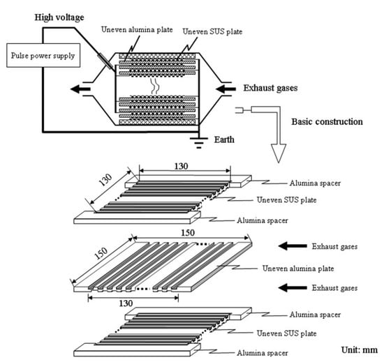
Figure 10.
The construction of the uneven DBD reactor. Reprinted from Ref. [91], with permission from John Wiley and Sons.
Yoshioka and co-workers developed a new method for PM removal from the exhaust gas of 2.4 kVA diesel engine [93]; this was corona discharge based on 9 trays of the conventional engine oil or treated water with a surfactant, to enhance the PM absorbent of water. The corona was generated by 9 copper wires (0.3 mm in diameter) along with 9 aluminum plates, and the distance between wire and plate were fixed at 30 mm, as shown in Figure 11. The discharge current of water trays was higher than that of oil trays; moreover, the discharge current increased toward the water depth, but it changed negligibly by the oil depth, as shown in Figure 12. The PM removal test indicated that more than 85% of PM in the exhaust gas from the diesel was absorbed by the system in both cases of oil or water trays. The PM has been absorbed in the water or oil which can be easily replaced by fresh water and oil; therefore, the PM removal system can be operated with a long time.
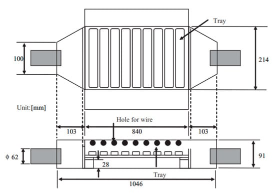
Figure 11.
The schematic of PM removal device with wires electrode and trays electrode. Reprinted from Ref. [93], with permission from John Wiley and Sons.
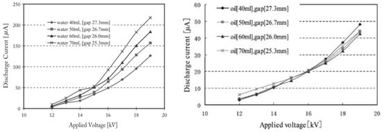
Figure 12.
The relation between discharge current of the PM removal device and different air gap from wire electrode to trays electrode (a) the trays electrode on water (b) the trays electrode on oil. Reprinted from Ref. [93], with permission from John Wiley and Sons.
Gu et al. [94] investigated the effect of O3 injection, the outlet of DBD oxygen plasma was injected behind the diesel exhaust and upstream of the DPF. The PM source was from a diesel engine exhaust gas (4 cylinders and 4 strokes) at 2400 rpm with a load mode of 25%, 50%, 70%, or 100%. Under the O3 injection by the DBD plasma coupled with the DPF, the system removed 98% particle quantity concentration of PM in the DEG. Moreover, the presence of plasma also decreased sizes of PM, i.e., mean diameter decreased from 45.3 mm to 41.6 mm after injecting the plasma.
4.2.3. Simultaneous Removal of DPM and NOx
In 1994, Fanick et al. [66] firstly reported on the simultaneous removal of DPM and NOx using plasma technology. The DEG sources were from two different light-duty diesel vehicles, i.e., a 1982 Toyota pick-up truck and 1991 Dodge pick-up truck. The plasma reactor used was a bed reactor of a barium titanate ceramic. The simultaneous removal of DPM and NOx was investigated in the gas space velocity range from 1400 to 20,000 h−1 for both exhaust gases from these vehicles. The experiments demonstrated that the bed reactor was capable of simultaneous removal of DPM and NOx from a light-duty diesel vehicle. Specifically, the ER was above 60% for almost conditions; however, the ER decreased with increasing gas hourly space velocity. The presence of plasma discharge led to an increase in CO concentration in the after-treatment gas. Moreover, the conversion of CO and NOx also depended on the gas hourly space velocity; particularly, they decreased when the gas velocity increased. However, the energy consumption of the plasma reactor was not reported in this study.
The simultaneous removal of PM and NOx was investigated in a packed DBD with 2.0 wt.% Ag over Al2O3 as a selective catalyst reduction [95]; moreover, in order to compare, other catalysts such as γ-Al2O3, In/ZSM-5, Na-Y/zeolite, and Ag-Coated Ferrierrite were also examined for PM and NOx removal. Among the catalysts in combination with plasma, Ag/Al2O3 catalyst was an effective catalyst for NO removal at temperature 250–350 °C and gas hourly space velocity of 10,000 h−1. Specifically, the combination of plasma with catalyst was crucial for NO removal in the temperature from 150 to 250 °C; the temperature was insufficient for the catalyst activation in the case of catalyst alone. The NO removal increased toward the ratio of C/NOx up to 6. Here, C/NOx was a ratio of C in the hydrocarbons as a reducing agent per N in NOx in the feed. The result also indicated that ED ≤ 30 J/L of plasma could be sufficient for the process over Ag/Al2O3. The selective catalyst reduction was capable of simultaneous removal of PM and NOx by an NTP through a packed-bed DBD reactor.
Mok and Hub [96] investigated the simultaneous removal of NOx and PM from a diesel engine exhaust by a hybrid process of DBD and catalysis. The original exhaust gas from the diesel engine consisted of NO as a major form of NOx; however, a part of NO oxidized into NO2 after pre-plasma discharge by the DBD stage. As a result, an increasing fraction of NO2 in the feed gas was introduced to the second stage through the V2O5/TiO2 monolith catalyst located in the oven. With the feed in the second stage being a mixture of NO and NO2, the efficiency reduction of NOx by the catalyst was increased, as shown in Figure 13. Particularly, the plasma catalysis hybrid process was able to remove about 80% of the initial NOx at an ED of 25 J/L and 150 °C; while only plasma or catalyst was 10% or 45%, respectively, under these conditions. In the case of PM removal, ER increased from 50% to 80% for the ED range of (20–40 J/L). To sum up, a hybrid process of the DBD with the catalyst could be applied to the simultaneous removal of NOx and PM.
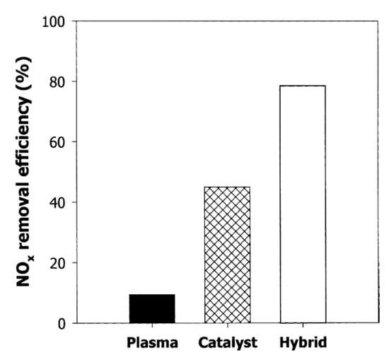
Figure 13.
Comparison of NOx removal efficiencies between hybrid plasma-catalyst with each stage at 150 °C and ED of 25 J/L. Reprinted from Ref. [96], with permission Springer Nature.
Simultaneous removal of NOx, HC, and PM from an actual DEG in a DBD was investigated by Song et al. [97] in 2009; the plasma discharge was driven by an AC high voltage with a peak voltage of 0–14 kV along with a frequency of 10–27 kHz. The authors examined several key factors of plasma discharge on the contaminant removals, namely peak voltage, frequency, and gas component by adjusting engine load. When maintained frequency at 15.5 kHz, a high-peak voltage to the level off-peak voltage led to an increase in the removal efficiency of HC and PM; whereas, the efficiency of NO started to decrease when the peak voltage was above 8 kV (≥240 J/L). At peak voltage of 8 kV, the efficiency of contaminant removal increased with the frequency from 12.5 to 15.5 kHz; afterward, an increase in frequency led to a decrease in the removal efficiencies. The system exhibited the highest PM, HC, and NOx removal efficiencies of 80%, 75%, and 65%, respectively; additionally, removal of SOF seems to be accessible than polycyclic aromatic hydrocarbons in the plasma discharge.
The plasma discharge of the DEG in a DBD for simultaneous removal of NOx and PM was investigated with a high voltage from 7.5 to 13.5 kVp-p at the frequency of 50 Hz [98]. Herein, the actual DEG was provided by a diesel engine (0.4-L, 2-cylinder, 4-stroke) at 2 kW engine load; the exhaust gas was cooled to room temperature before entering to the DBD reactor. The results show that the plasma discharge was successful for the treatment of NOx and PM, especially for soot removal; the highest removal efficiency for NOx, soot, and SOF was 18%, 73%, and 37%, respectively, at ED of 27 J/L.
5. Limitation of Energy Consumption in Practical Plasma Applications
This section discussed the limitation of ED by plasma to DEG treatment. In the case of high energy efficiency of diesel engines, the temperature of exhaust gases is often low range temperature, e.g., from 150 to 350 °C by typical diesel passenger cars [10,99]. Saud et al. [100] proposed a novelty catalyst working well with the high range temperature of the exhaust gas, i.e., gas temperature in the range of 250–350 °C. Consequently, to activate the catalyst, the exhaust gas temperature must be maintained in this range. During the automobile operation, the cold start or light load mode has resulted in a low exhaust gas temperature. This proposes to heat the exhaust gas to reach the activated catalyst temperature, herein, considering the range from 150 to 250 °C. The ED for heating the exhaust gas can be estimated by integration of heat capacity at constant pressure (Cp, J/kmol.K) with temperature from T1 to T2, as shown in Equation (4).
The gas composition of DEGs is complicated chemicals, as shown in Table 1; however, the primary component is N2, O2, and H2O. Consequently, with approximated calculation, the heat capacity of air can be considered as the exhaust gas in the temperature range. The Cp of air as a function of temperature is given in Equation (5), with a validated temperature of 50–1500 K [101]
where: C1 = 28,958, C2 = 9390, C3 = 3012, C4 = 7580, and C5 = 1484.
Consequently, ED for heating air from T1 to T2 (K) can be estimated by Equation (6) [100].
Cp as a function of temperature and gas temperature as a function of ED with the initial temperature of 150 °C were plotted in Figure 14. As seen from this Figure 14a, Cp was slightly changed from 1.198 to 1.219 J/L K within the temperature range. Consequently, the average Cp in this temperature range was 1.208 J/L K, suggesting an ED requirement of 1.208 J/L to heat up 1 °C. The ED required for heating the gas up to 250 °C with the initial gas temperature at least 150 °C is up to 120 J/L. At gas temperatures insufficient for the catalyst activation, there are two ways of delivering energy to the catalyst system, namely thermal heating, and plasma discharge. The comparison between two methods indicated that energy delivery through plasma could obtain high efficiency than the other in the case of SCR-NOx removal at low range temperature [102]. Furthermore, the range of ED up to 120 J/L is sufficient for the plasma-catalyst process. However, from a practical viewpoint, the ED should be as small as possible due to limited energy battery supply and fuel consumption. If the energy consumption for catalysts with/out plasma is accounted for approximately 5% of fuel energy combustion during engine operating, suggesting, ED is around 30 J/L. Furthermore, this is a reason why the ED of plasma is about 30 J/L for investigating plasma for DEG treatment [82,88,89,95,96,98]. With the range of ED used to heat gas, the gas temperature increased by 25 °C, see Figure 14b. In the case of the initial temperature of less than 225 °C, the gas temperature is still insufficient to obtain the activated catalyst temperature. However, the NOx removal increased significantly with the ED level of 30 J/L through the plasma discharge, as shown in Figure 5, Figure 9, Figure 13, and Figure 15. Therefore, a combination of plasma with a catalyst is essential for both contaminant removal and energy consumption.
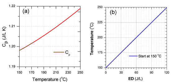
Figure 14.
(a) Cp of air with temperature from 150 °C to 250 °C and (b) air temperature as a function of ED with the initial temperate at 150 °C (Cp and ED calculated with volume gas at 25 °C).
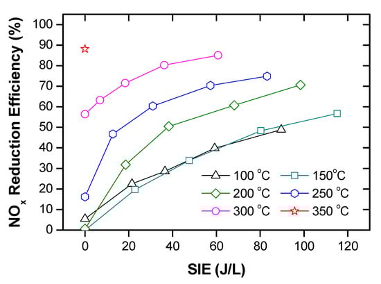
Figure 15.
NOx removal as a function of temperature and ED in a packed-bed DBD reactor. It adopted from Ref. [102], with permission from Elsevier.
6. Conclusion and Future of DPM Treatment by Atmospheric Pressure Plasma
According to the above review on the PM removal in the literature, the application of atmospheric pressure plasma technology for DPM treatment from DEG is a promising solution compared to the other technologies. Using DPFs (or CDPFs) technology independently trapped significant PM emissions. However, there are several unsolved problems such as low ultrafine particle filtration efficiency, a difficult filter regeneration at low-temperature, and high backpressure. This problem requires frequency to replace filters by new ones, resulting in economic inefficiency. For DOCs technology, deposition of metal sulfate founded by sulfur oxidation to SO3 at high temperature is susceptible to be poisoned, and when enters the inhalation system seriously affect human health. In this case, plasma technology with low temperatures can regenerate the particulate filter, direct DPMs treatment, and simultaneous removal of PM and NOx.
For purifying DEG with the assisted plasma, the temperature of regeneration can occur at the temperature range of DEG (150–350 °C), the lowest temperature to regenerate DPF observed at 80 °C when combining with NTP reactor. In several reports, the PM from DEG eliminated under the presence of plasma. The removal efficiency of the contaminate DEG was also significant with the input energy of plasma around 30 J/L, the desired energy consumption. Interestingly, this system could be utilized even at low exhaust temperatures with a cold start or light load mode of diesel engines; simultaneous removal DPM and NOx can be performed with a plasma-catalyst process.
Atmospheric pressure plasma is an effective method for treating DEG, presenting in lab-scales, and several pilot tests with simulated or actual DEG. However, up to date, a commercial plasma application for treating DEG from diesel vehicles is not exhibited. Several characteristics of the existent systems are small gaps with a pack-bed DBD, specialized plasma power supply (pulse, high frequency), or complicated systems. Consequently, there are challenges when transferring from research to practical application. Another challenge to this is limited energy consumption for plasma, which should be less than 5% of the total fuel consumption. In other words, the energy consumption for plasma is approximately 30 J/L with the DEG. With less of input energy, however, the plasma system must provide sufficient energy efficiency for PM removal, as well as other contaminant chemicals, in a practical application of DEG treatment.
Funding
This research was funded by the National Natural Science Foundation of China grant number 51972050 and the Joint Guidance Project of Natural Science Foundation by Heilongjiang Province, grant number LH2020E006.
Acknowledgments
The authors gratefully acknowledge the academic support of the Lab of Automobile Emission Testing and Control Laboratory, College of Mechanical and Electric Engineering at Northeast Forestry University, Harbin, China; Department of Science and Technology, Quang Ninh, Viet Nam. Also, the authors would like to thanks the reviewer for their valuable remarks and comments.
Conflicts of Interest
The authors declare no conflict of interest.
Abbreviations
| CDPF | Catalytic diesel particulate filter |
| CRT | Continuous regeneration trap |
| DBD | Dielectric barrier discharge |
| DEG | Diesel exhaust gas |
| DPM | Diesel particulate matter |
| DPF | Diesel particulate filters |
| DOC | Diesel oxidation catalyst |
| ED | Energy density |
| ER | Efficiency of PM removal |
| EE | Energy efficiency |
| NOx | Nitrogen oxides |
| NTP | Non-thermal plasma |
| PM | Particulate matter |
| POC | Particle oxidation catalysts |
| PACs | Polycyclic aromatic compounds |
| SOF | Solube organic fraction |
| SF | Sulfur fraction |
| SCR | Selective catalytic reduction |
Appendix A
Table A1.
A comprehensive review of published papers featuring non-thermal plasma for DPM treatment from simulated PM sources.
Table A1.
A comprehensive review of published papers featuring non-thermal plasma for DPM treatment from simulated PM sources.
| Authors | Treatment | Plasma | PM Source | Catalyst | Remarks | Ref. |
|---|---|---|---|---|---|---|
| Kim et al., 2002 | DPF regeneration | DBD | C3H6, Carbon black | N/A | Soot oxidation at 230 °C ∆P = 14.2 mbar, CO = 952 ppm and CO2 = 314 ppm after 50 min at 350 °C | [67] |
| Okubo et al., 2004 | Corona discharge | Automobile diesel engine, medium load mode for 2 h | ER = 75% at 250 °C and ED of 40 J/L | [82] | ||
| Okubo et al., 2004 | Needle-to-plate barrier | Carbon soot loaded on DPF | ER= 97% at 300 °C with regeneration time of 4.6 h. | [68] | ||
| Shi et al., 2014 | DBD/O3 injection | PM loaded on DPF from diesel engine | ER = 100 % at 80 °C after 2 h injection of O2 plasma | [80] | ||
| Yao et al., 2001 | Direct DPM removal | DBD | Methane /active carbon | EE: 3–7.5 g(C)/kWh and 3–30 g(C)/kWh for methane and active carbon, respectively. Selectivity of (CO and CO2) ≥ 90% | [65] | |
| Suzuki et al., 2008 | DBD | Carbon black | ER ≥ 80% with any ratio N2:O2 (8:2, 9:1 and 10:0) CO2 generated under plasma conditions from 0–12 W | [84] | ||
| Okubo et al., 2010 | Simultaneous removal of DPM and NOx | Packed-bed DBD | Carbon PM load from diesel engine | BaTiO3 | EE: 1.31 g(N)/kWh and 2.2 g(PM)/kWh | [71] |
| Okubo et al., 2017 | Packed-bed DBD | Carbon PM load from diesel engine | Ag/γ-Al2O3 | EE: 4.32 g(N)/kWh and 0.92 g(C)/kWh | [45] | |
| Nguyen et al., 2019 | Packed-bed DBD | Naphthalene (C10H8) | Ag/α-Al2O3 | ER: 90% for soot and NOx at 350 °C and ED 90 J/L EE: 6.18 g(N)/kWh and 8.48 g(C)/kWh (only C in naphthalene) | [2] |
ER: efficiency of removal, EE: energy efficiency, ED: energy density of input plasma, and N/A: not applicable.
Table A2.
A comprehensive review of published papers featuring non-thermal plasma for DPM treatment from diesel engines.
Table A2.
A comprehensive review of published papers featuring non-thermal plasma for DPM treatment from diesel engines.
| Authors | Treatment | Plasma | PM PM Source | Catalyst | Remarks | Ref. |
|---|---|---|---|---|---|---|
| Okubo et al., 2008 | DPF regeneration | Two NTP reactors | J106-STD, 4 cycles, two-cylinders | Zeolite pellets/Glass pellets | EE: 6.6 g (PM)/kWh and 4.9 g(N)/kWh | [59] |
| Okubo et al., 2009 | Corona discharge | Small diesel engine (displacement volume 219 mL, power 1 kW) | N/A | EE = 6.74 g (PM)/kWh ER = 62.2% with a process time of 79 min | [77] | |
| Pu et al., 2018 | DBD/O3 injection | 4-cylinder diesel engine; 75% load (2500 r/min, 69 N.m) for 3 h | PM loading: 12.5 g C ER: 90 % at 100 °C | [87] | ||
| Pu et al., 2018 | DBD/O3 injection | A one-cylinder diesel engine; 3 h loading | EE: 14.93 g(PM)/kWh | [81] | ||
| Thomas et al., 2000 | Direct DPM removal | DBD | Nissan 2.7 L IDI | With/out Ceramic pellets | ER: 90% EE = 2.94 g(PM)/kWh at ED of 18 J/L | [88] |
| Dan et al., 2005 | DBD | Gasoline engine | Cu/ZSM-5 | ER: ~57% for PM and HC at ED of 36 J/L | [89] | |
| Yao et al., 2006 | Uneven DBD | Toyota, 4-cylinder, 2 L diesel engine | N/A | ER = 67% EE: 3–10.6 g(PM)/kWh | [69] | |
| Yao et al., 2007 | Uneven DBD reactor | Toyota, 4-cylinder, 2 L diesel engine | N/A | ER: 75–100% along with EE: 16–0.34 g/kWh | [91] | |
| Fushimi et al., 2006 | Uneven DBD reactor with 20/50-pair electrodes | Toyota, 2 L, 4-cycle, direct injection | N/A | ER = 47–84% and EE = 2.9–0.85 g(PM)/kWh (for 20 pairs) ER = 87–94% and EE = 13.7–3.6 g(PM)/kWh (for 50 pairs) | [92] | |
| Fushimi et al., 2008 | Uneven DBD reactor | Toyota, 2 L, 4-cycle, direct injection | N/A | ER = 50–76% EE = 3.9–11.6 g(PM)/kWh | [70] | |
| Gu et al., 2017 | DBD/O3 injection | 4 cylinders, Diesel engine 4 strokes | N/A | ER = 98% | [94] | |
| Fanick et al., 1994 | Simultaneous removal of DPM and NOx | Bed reactor | Toyota truck and Dodge truck | Barium titanate ceramic | ER for PM and NOx were 60% and 40%, respectively | [66] |
| Thomas et al., 2001 | Packed-bed DBD | Diesel generator (Lombardini 5kVA) | γ-Al2O3, Ag/Al2O3, In/ZSM-5, Na-Y/Zeolite, Ag-Ferrierite | ER for NO: ≥50% over Ag/Al2O3 at temperature 250–350 °C, and ED = 30 J/L Plasma coupled with Ag/Al2O3 is suitable simultaneous removal of PM and NOx | [95] | |
| Mok & Huh 2005 | Hybrid of DBD and catalyst | Diesel engine | V2O5/TiO2 | (PM) ER = 50–80% corresponding to EE: 0.054–0.043 g(PM)/kWh (ED: 20–40 J/L (NOx) ER = 80% and EE = 11.9 g(N)/kWh at ED of 25 J/L and 150 °C | [96] | |
| Song et al., 2009 | DBD | Diesel engine | N/A | ER: PM, NOx and HC were 80%, 65%, and 75%, respectively. EE: 0.18 to 0.99 g(PM)/kWh | [97] | |
| Babaie et al., 2016 | DBD | 0.4 L, 2-cylinder, 4-stroke diesel engine | N/A | ER for soot, NOx and SOF was 73%, 18% and 37%, respectively, at ED 27 J/L | [98] | |
| Yoshioka et al., 2006 | Absorbed PM | DC corona discharge | Diesel engine 2.4 kVA | Oil trays/water trays | ER = 85% | [93] |
ER: efficiency of removal, EE: energy efficiency, ED: energy density of input plasma, and N/A: not applicable.
References
- Talebizadeh, P.; Babaie, M.; Brown, R.; Rahimzadeh, H.; Ristovski, Z.; Arai, M. The role of non-thermal plasma technique in NOx treatment: A review. Renew. Sustain. Energy Rev. 2014, 40, 886–901. [Google Scholar] [CrossRef]
- Nguyen, V.T.; Nguyen, D.B.; Heo, I.; Mok, Y.S. Plasma-Assisted Selective Catalytic Reduction for Low-Temperature Removal of NOx and Soot Simulant. Catalysts 2019, 9, 853. [Google Scholar] [CrossRef]
- Gao, J.B.; Ma, C.C.; Xing, S.K.; Sun, L.W.; Huang, L.Y. A review of fundamental factors affecting diesel PM oxidation behaviors. Sci. China Ser. E Technol. Sci. 2017, 61, 330–345. [Google Scholar] [CrossRef]
- Shangguan, W.; Zou, G.; Jiang, Z. Simultaneous Catalytic Removal of Diesel Soot and NOx; Springer: Singapore, 2019. [Google Scholar]
- De Lucas, A.; Durán, A.; Carmona, M.; Lapuerta, M. Characterization of Soluble Organic Fraction in DPM: Optimization of the Extraction Method. SAE Tech. Pap. 1999. [Google Scholar] [CrossRef]
- Farrar-Khan, J.R.; Andrews, G.E.; Williams, P.T.; Bartle, K.D. The Influence of Nozzle Sac Volume on the Composition of Diesel Particulate Fuel Derived SOF. SAE Tech. Pap. 1992. [Google Scholar] [CrossRef]
- Kittelson, D.B. Engines and nanoparticles: A review. J. Aerosol Sci. 1998, 29, 575–588. [Google Scholar] [CrossRef]
- Khair, M.K. A Review of Diesel Particulate Filter Technologies. SAE Tech. Pap. 2003. [Google Scholar] [CrossRef]
- Guo, X.R.; Du, D.; Wang, F.; Ma, Y.; Yang, C.; Zhang, H.-Z. Study on test instrument and filtration theory of the carbonized micron wood fiber DPF. Microporous Mesoporous Mater. 2011, 142, 655–660. [Google Scholar] [CrossRef]
- Yao, S. Plasma reactors for diesel particulate matter removal. Recent Patents Chem. Eng. 2009, 2, 67–75. [Google Scholar] [CrossRef]
- Zheng, Y.; Luss, D.; Harold, M.P. Optimization of LNT-SCR Dual-Layer Catalysts for Diesel NOx Emission Control. SAE Int. J. Engines 2014, 7, 1280–1289. [Google Scholar] [CrossRef]
- Zheng, Y.; Liu, Y.; Harold, M.P.; Luss, D. LNT–SCR dual-layer catalysts optimized for lean NOx reduction by H2 and CO. Appl. Catal. B Environ. 2014, 148–149, 311–321. [Google Scholar] [CrossRef]
- Zelenka, P.; Cartellieri, W.; Herzog, P. Worldwide diesel emission standards, current experiences and future needs. Appl. Catal. B Environ. 1996, 10, 3–28. [Google Scholar] [CrossRef]
- Du, D.; Guo, X.; Xu, Y.; Yang, X. Performance study about a new kind wood fiber filter element utilized in capturing diesel particulate material. J. Wood Sci. 2019, 65, 12. [Google Scholar] [CrossRef]
- Wade, J.; Farrauto, R.J. Controlling emissions of pollutants in urban areas. In Metropolitan Sustainability: Understanding and Improving the Urban Environment; Zeman, F., Ed.; Woodhead Publishing: Cambridge, UK; Philadelphia, PA, USA, 2012; pp. 260–291. [Google Scholar] [CrossRef]
- Prasad, R.; Bella, V.R. A Review on Diesel Soot Emission, its Effect and Control. Bull. Chem. React. Eng. Catal. 2010, 5, 69–86. [Google Scholar] [CrossRef]
- Jung, H.; Kittelson, D.B.; Zachariah, M.R. The influence of a cerium additive on ultrafine diesel particle emissions and kinetics of oxidation. Combust. Flame 2005, 142, 276–288. [Google Scholar] [CrossRef]
- Vaaraslahti, K.; Ristimäki, J.; Virtanen, A.; Keskinen, J.; Giechaskiel, B.; Solla, A. Effect of Oxidation Catalysts on Diesel Soot Particles. Environ. Sci. Technol. 2006, 40, 4776–4781. [Google Scholar] [CrossRef]
- Liu, Z.; Ge, Y.; Tan, J.; He, C.; Shah, A.N.; Ding, Y.; Yu, L.; Zhao, W. Impacts of continuously regenerating trap and particle oxidation catalyst on the NO2 and particulate matter emissions emitted from diesel engine. J. Environ. Sci. 2012, 24, 624–631. [Google Scholar] [CrossRef]
- Guan, C.; Li, X.; Liao, B.; Huang, Z. Effects of fuel injection strategies on emissions characteristics of a diesel engine equipped with a particle oxidation catalyst (POC). J. Environ. Chem. Eng. 2016, 4, 4822–4829. [Google Scholar] [CrossRef]
- Gholami, F.; Tomas, M.; Gholami, Z.; Vakili, M. Technologies for the nitrogen oxides reduction from flue gas: A review. Sci. Total Environ. 2020, 714, 136712. [Google Scholar] [CrossRef]
- Lin, F.W.; Wang, Z.H.; Zhang, Z.M.; He, Y.; Zhu, Y.Q.; Shao, J.M.; Yuan, D.K.; Chen, G.Y.; Cen, K. Flue gas treatment with ozone oxidation: An overview on NOx, organic pollutants, and mercury. Chem. Eng. J. 2020, 382, 123030. [Google Scholar] [CrossRef]
- Li, S.; Dang, X.; Yu, X.; Abbas, G.; Zhang, Q.; Cao, L. The application of dielectric barrier discharge non-thermal plasma in VOCs abatement: A review. Chem. Eng. J. 2020, 388, 124275. [Google Scholar] [CrossRef]
- Mohankumar, S.; Senthilkumar, P. Particulate matter formation and its control methodologies for diesel engine: A comprehensive review. Renew. Sustain. Energy Rev. 2017, 80, 1227–1238. [Google Scholar] [CrossRef]
- Hiranuma, S.; Takeda, Y.; Kawatani, T.; Doumeki, R.; Nagasaki, K.; Ikeda, T. Development of DPF System for Commercial Vehicle—Basic Characteristic and Active Regenerating Performance. SAE Trans. 2003, 112, 2381–2387. [Google Scholar] [CrossRef]
- Palma, V.; Ciambelli, P.; Meloni, E. Optimising the catalyst load for microwave susceptible catalysed DPF. Chem. Eng. Trans. 2012, 29, 637–642. [Google Scholar]
- Meloni, E.; Palma, V.; Vaiano, V. Optimized microwave susceptible catalytic diesel soot trap. Fuel 2017, 205, 142–152. [Google Scholar] [CrossRef]
- Shangguan, W.F.; Teraoka, Y.; Kagawa, S. Promotion effect of potassium on the catalytic property of CuFe2O4 for the simultaneous removal of NOx and diesel soot particulate. Appl. Catal. B Environ. 1998, 16, 149–154. [Google Scholar] [CrossRef]
- Wang, Z.; Jiang, Z.; Shangguan, W. Simultaneous catalytic removal of NOx and soot particulate over Co-Al mixed oxide catalysts derived from hydrotalcites. Catal. Commun. 2007, 8, 1659–1664. [Google Scholar] [CrossRef]
- Wang, Z.; Shangguan, W.; Su, J.; Jiang, Z. Catalytic oxidation of diesel soot on mixed oxides derived from hydrotalcites. Catal. Lett. 2006, 112, 149–154. [Google Scholar] [CrossRef]
- Makshina, E.V.; Sirotin, S.V.; Yushchenko, V.V.; Mazo, G.N.; Berg, M.W.E.V.D.; Klementsev, K.V.; Grünert, W.; Romanovskii, B.V. Nanocomposites based on LaCoO3 and mesoporous molecular sieves: Preparation and physicochemical and catalytic properties. Kinet. Catal. 2006, 47, 49–53. [Google Scholar] [CrossRef]
- Zou, G.; Chen, M.; Shangguan, W. Promotion effects of LaCoO3 formation on the catalytic performance of Co–La oxides for soot combustion in air. Catal. Commun. 2014, 51, 68–71. [Google Scholar] [CrossRef]
- Kirienko, P.I.; Solovev, S.A.; Orlik, S.N. Magnetic properties of Co3O4 nanoparticles. Theor. Exp. Chem. 2010, 46, 39–44. [Google Scholar] [CrossRef]
- Tendero, C.; Tixier, C.; Tristant, P.; Desmaison, J.; Leprince, P. Atmospheric pressure plasmas: A review. Spectrochim. Acta Part B At. Spectrosc. 2006, 61, 2–30. [Google Scholar] [CrossRef]
- Rutscher, A. Characteristics of Low-Temperature Plasmas Under Nonthermal Conditions—A Short Summary. In Low Temperature Plasmas: Fundamentals, Technologies and Techniques, 2nd ed.; Wiley-VCH: Weinheim, Germany, 2008; pp. 1–14. [Google Scholar]
- Bruggeman, P.J.; Iza, F.; Brandenburg, R. Foundations of atmospheric pressure non-equilibrium plasmas. Plasma Sources Sci. Technol. 2017, 26, 123002. [Google Scholar] [CrossRef]
- Cools, P.; De Geyter, N.; Morent, R. Plasma-Catalytic Removal of VOCs; Springe: Singapore, 2019; pp. 145–180. [Google Scholar]
- Adamovich, I.; Baalrud, S.D.; Bogaerts, A.; Bruggeman, P.; Cappelli, M.; Colombo, V.; Czarnetzki, U.; Ebert, U.; Eden, J.G.; Favia, P.; et al. The 2017 Plasma Roadmap: Low temperature plasma science and technology. J. Phys. D Appl. Phys. 2017, 50, 323001. [Google Scholar] [CrossRef]
- Shi, Y.; Cai, Y.; Li, X.; Ji, L.; Chen, Y.; Wang, W. Evolution of diesel particulate physicochemical properties using nonthermal plasma. Fuel 2019, 253, 1292–1299. [Google Scholar] [CrossRef]
- Raju, B.R.; Reddy, E.L.; Karuppiah, J.; Reddy, P.M.K.; Subrahmanyam, C. Catalytic non-thermal plasma reactor for the decomposition of a mixture of volatile organic compounds. J. Chem. Sci. 2013, 125, 673–678. [Google Scholar] [CrossRef]
- Ondarts, M.; Hajji, W.; Outin, J.; Bejat, T.; Gonze, E. Non-Thermal Plasma for indoor air treatment: Toluene degradation in a corona discharge at ppbv levels. Chem. Eng. Res. Des. 2017, 118, 194–205. [Google Scholar] [CrossRef]
- Chmielewski, A.G.; Iller, E.; Tyminski, B.; Zimek, Z.; Licki, J. Flue gas treatment by electron beam technology. Mod. Power Syst. 2001, 53–54. [Google Scholar]
- Licki, J.; Pawelec, A.; Zimek, Z.; Witman-Zając, S. Electron beam treatment of simulated marine diesel exhaust gases. Nukleonika 2015, 60, 689–695. [Google Scholar] [CrossRef]
- Yoshida, K. Aftertreatment of Carbon Particles Emitted by Diesel Engine Using a Combination of Corona and Dielectric Barrier Discharge. IEEE Trans. Ind. Appl. 2019, 55, 5261–5268. [Google Scholar] [CrossRef]
- Okubo, M.; Yamada, H.; Yoshida, K.; Kuroki, T. Simultaneous Reduction of Diesel Particulate and NOx Using a Catalysis-Combined Nonthermal Plasma Reactor. IEEE Trans. Ind. Appl. 2017, 53, 5875–5882. [Google Scholar] [CrossRef]
- Wang, T.; Sun, B.-M.; Xiao, H.-P.; Zeng, J.-Y.; Duan, E.-P.; Xin, J.; Li, C. Effect of Reactor Structure in DBD for Nonthermal Plasma Processing of NO in N2 at Ambient Temperature. Plasma Chem. Plasma Process. 2012, 32, 1189–1201. [Google Scholar] [CrossRef]
- Homola, T.; Pongrác, B.; Zemánek, M.; Šimek, M. Efficiency of Ozone Production in Coplanar Dielectric Barrier Discharge. Plasma Chem. Plasma Process. 2019, 39, 1227–1242. [Google Scholar] [CrossRef]
- Jolibois, J.; Takashima, K.; Mizuno, A. Application of a non-thermal surface plasma discharge in wet condition for gas exhaust treatment: NOx removal. J. Electrost. 2012, 70, 300–308. [Google Scholar] [CrossRef]
- Jolibois, J.; Takashima, K.; Mizuno, A. NOx removal using a wet type plasma reactor based on a three-electrode device. J. Phys. Conf. Ser. 2011, 301, 012011. [Google Scholar] [CrossRef]
- Masuda, S.; Hosokawa, S.; Tu, X.-L.; Sakakibara, K.; Kitoh, S.; Sakai, S. Destruction of gaseous pollutants by surface-induced plasma chemical process (SPCS). IEEE Trans. Ind. Appl. 1993, 29, 781–786. [Google Scholar] [CrossRef]
- Lu, W.; Abbas, Y.; Mustafa, M.F.; Pan, C.; Wang, H. A review on application of dielectric barrier discharge plasma technology on the abatement of volatile organic compounds. Front. Environ. Sci. Eng. 2019, 13. [Google Scholar] [CrossRef]
- Vandenbroucke, A.M.; Morent, R.; De Geyter, N.; Leys, C. Non-thermal plasmas for non-catalytic and catalytic VOC abatement. J. Hazard. Mater. 2011, 195, 30–54. [Google Scholar] [CrossRef]
- Otto, K.; Sieg, M.; Zinbo, M.; Bartosiewicz, L. The Oxidation of Soot Deposits from Diesel Engines. SAE Trans. 1980, 89, 1399–1411. [Google Scholar] [CrossRef]
- Stanmore, B.R.; Brilhac, J.F.; Gilot, P. The oxidation of soot: A review of experiments, mechanisms and models. Carbon 2001, 39, 2247–2268. [Google Scholar] [CrossRef]
- Shi, Y.; Cai, Y.; Li, X.; Xu, H.; Li, W.; Pu, X. Low Temperature Diesel Particulate Filter Regeneration by Atmospheric Air Non-thermal Plasma Injection System. Plasma Chem. Plasma Process. 2016, 36, 783–797. [Google Scholar] [CrossRef]
- Wang, P.; Gu, W.; Lei, L.; Cai, Y.; Li, Z. Micro-structural and components evolution mechanism of particular matter from diesel engines with non-thermal plasma technology. Appl. Therm. Eng. 2015, 91, 1–10. [Google Scholar] [CrossRef]
- Fino, D.; Specchia, V. Open issues in oxidative catalysis for diesel particulate abatement. Powder Technol. 2008, 180, 64–73. [Google Scholar] [CrossRef]
- Levendis, Y.A.; Larsen, C.A. Use of Ozone-Enriched Air for Diesel Particulate Trap Regeneration. SAE Tech. Pap. 1999. [Google Scholar] [CrossRef]
- Okubo, M.; Arita, N.; Kuroki, T.; Yoshida, K.; Yamamoto, T. Total Diesel Emission Control Technology Using Ozone Injection and Plasma Desorption. Plasma Chem. Plasma Process. 2008, 28, 173–187. [Google Scholar] [CrossRef]
- Vinh, T.Q.; Watanabe, S.; Furuhata, T.; Arai, M. Effects of particulate matter on NOx removal in dielectric barrier discharges. J. Energy Inst. 2012, 85, 163–169. [Google Scholar] [CrossRef]
- Neri, G.; Bonaccorsi, L.; Donato, A.; Milone, C.; Musolino, M.G.; Visco, A.M. Catalytic combustion of diesel soot over metal oxide catalysts. Appl. Catal. B Environ. 1997, 11, 217–231. [Google Scholar] [CrossRef]
- Aubin, D.G.; Abbatt, J.P.D. Interaction of NO2 with Hydrocarbon Soot: Focus on HONO Yield, Surface Modification, and Mechanism. J. Phys. Chem. A 2007, 111, 6263–6273. [Google Scholar] [CrossRef]
- Messerer, A.; Niessner, R.; Pöschl, U. Comprehensive kinetic characterization of the oxidation and gasification of model and real diesel soot by nitrogen oxides and oxygen under engine exhaust conditions: Measurement, Langmuir–Hinshelwood, and Arrhenius parameters. Carbon 2006, 44, 307–324. [Google Scholar] [CrossRef]
- Takaki, K.; Hatanaka, Y.; Arima, K.; Mukaigawa, S.; Fujiwara, T. Influence of electrode configuration on ozone synthesis and microdischarge property in dielectric barrier discharge reactor. Vacuum 2008, 83, 128–132. [Google Scholar] [CrossRef]
- Yao, S.; Suzuki, E.; Nakayama, A. Oxidation of activated carbon and methane using a high-frequency pulsed plasma. J. Hazard. Mater. 2001, 83, 237–242. [Google Scholar] [CrossRef]
- Fanick, E.R.; Bykowski, B.B. Simultaneous Reduction of Diesel Particulate and NOx Using a Plasma. SAE Tech. Pap. 1994. [Google Scholar] [CrossRef]
- Kim, D.; Lee, H.-S.; Chun, K.M.; Hwang, J.; Lee, K.S.; Chun, B.-H. Comparison of Soot Oxidation by NO2 Only and Plasma-Treated Gas Containing NO2, O2, and Hydrocarbons. SAE Tech. Pap. 2002. [Google Scholar] [CrossRef]
- Okubo, M.; Kuroki, T.; Miyairi, Y.; Yamamoto, T. Low-Temperature Soot Incineration of Diesel Particulate Filter Using Remote Nonthermal Plasma Induced by a Pulsed Barrier Discharge. IEEE Trans. Ind. Appl. 2004, 40, 1504–1512. [Google Scholar] [CrossRef]
- Yao, S.; Fushimi, C.; Madokoro, K.; Yamada, K. Uneven Dielectric Barrier Discharge Reactors for Diesel Particulate Matter Removal. Plasma Chem. Plasma Process. 2006, 26, 481–493. [Google Scholar] [CrossRef]
- Fushimi, C.; Madokoro, K.; Yao, S.; Fujioka, Y.; Yamada, K. Influence of Polarity and Rise Time of Pulse Voltage Waveforms on Diesel Particulate Matter Removal Using an Uneven Dielectric Barrier Discharge Reactor. Plasma Chem. Plasma Process. 2008, 28, 511–522. [Google Scholar] [CrossRef]
- Okubo, M.; Kuroki, T.; Yoshida, K.; Yamamoto, T. Single-Stage Simultaneous Reduction of Diesel Particulate and NOx Using Oxygen-Lean Nonthermal Plasma Application. IEEE Trans. Ind. Appl. 2010, 46, 2143–2150. [Google Scholar] [CrossRef]
- Kojetin, P.; Janezich, F.; Sura, L.; Tuma, D. Production Experience of a Ceramic Wall Flow Electric Regeneration Diesel Particulate Trap. SAE Trans. 1993, 102, 198–210. [Google Scholar] [CrossRef]
- Ichikawa, Y.; Yamada, S.-I.; Yamada, T. Development of Wall-Flow Type Diesel Particulate Filter System with Efficient Reverse Pulse Air Regeneration. SAE Tech. Pap. 1995. [Google Scholar] [CrossRef]
- Suzuki, J.; Matsumoto, S. Development of Catalysts for Diesel Particulate NOx Reduction. Top. Catal. 2004, 28, 171–176. [Google Scholar] [CrossRef]
- Fino, D. Diesel emission control: Catalytic filters for particulate removal. Sci. Technol. Adv. Mater. 2007, 8, 93–100. [Google Scholar] [CrossRef]
- Kong, Y.; Kozakiewicz, T.; Johnson, R.; Huffmeyer, C.; Huckaby, J.; Abel, J.; Baurley, J.; Duffield, K. Active DPF Regeneration for 2007 Diesel Engines. SAE Tech. Pap. 2005. [Google Scholar] [CrossRef]
- Okubo, M.; Kuroki, T.; Kawasaki, S.; Yoshida, K.; Yamamoto, T. Continuous Regeneration of Ceramic Particulate Filter in Stationary Diesel Engine by Nonthermal-Plasma-Induced Ozone Injection. IEEE Trans. Ind. Appl. 2009, 45, 1568–1574. [Google Scholar] [CrossRef]
- Okubo, M.; Kuwahara, T.; Yoshida, K.; Kannaka, Y.; Kuroki, T. Improvement of NOx Reduction Efficiency in Diesel Emission Using Nonthermal Plasma—Exhaust Gas Recirculation Combined Aftertreatment. In Proceedings of the 2010 IEEE Industry Applications Society Annual Meeting, Houston, TX, USA, 3–7 October 2010. [Google Scholar] [CrossRef]
- Shi, Y.; Cai, Y.; Wang, J.; Pu, X.; Linbo, G. Influence of PM Size Distribution and Ingredients on DPF Regeneration by Non-thermal Plasma Technology. Plasma Chem. Plasma Process. 2017, 37, 451–464. [Google Scholar] [CrossRef]
- Shi, Y.X.; Cai, Y.X.; Li, X.H.; Chen, Y.Y.; Ding, D.W.; Tang, W. Meachanism and method of DPF regeneration by oxygen radical generated by NTP technology. Int. J. Automot. Technol. 2014, 15, 871–876. [Google Scholar] [CrossRef]
- Pu, X.; Cai, Y.; Shi, Y.; Wang, J.; Gu, L.; Tian, J.; Li, W. Diesel particulate filter (DPF) regeneration using non-thermal plasma induced by dielectric barrier discharge. J. Energy Inst. 2018, 91, 655–667. [Google Scholar] [CrossRef]
- Okubo, M.; Miyashita, T.; Kuroki, T.; Miwa, S.; Yamamoto, T. Regeneration of Diesel Particulate Filter Using Nonthermal Plasma Without Catalyst. IEEE Trans. Ind. Appl. 2004, 40, 1451–1458. [Google Scholar] [CrossRef]
- Hoard, J.; Laing, P.; Balmer, M.L.; Tonkyn, R. Comparison of Plasma-Catalyst and Lean NOx Catalyst for Diesel NOx Reduction. SAE Trans. 2000, 109, 2729–2736. [Google Scholar] [CrossRef]
- Suzuki, K.-I.; Takeuchi, N.; Madokoro, K.; Fushimi, C.; Yao, S.; Fujioka, Y.; Nihei, Y. Removal Properties of Diesel Exhaust Particles by a Dielectric Barrier Discharge Reactor. Anal. Sci. 2008, 24, 253–256. [Google Scholar] [CrossRef][Green Version]
- Tran, Q.-V.; Arai, M. A New After-treatment Concept of Diesel Exhaust Gas Using Barrier Discharge Reactor Combined with Diesel Particulate Filter. SAE Tech. Pap. 2013. [Google Scholar] [CrossRef]
- Vinh, T.Q.; Watanabe, S.; Furuhata, T.; Arai, M. Fundamental study of NOx removal from diesel exhaust gas by dielectric barrier discharge reactor. J. Mech. Sci. Technol. 2012, 26, 1921–1928. [Google Scholar] [CrossRef]
- Pu, X.; Cai, Y.; Shi, Y.; Wang, J.; Gu, L.; Tian, J.; Fan, R. Carbon Deposit Incineration During Engine Flameout Using Non-Thermal Plasma Injection. Int. J. Automot. Technol. 2018, 19, 421–432. [Google Scholar] [CrossRef]
- Thomas, S.E.; Martin, A.R.; Raybone, D.; Shawcross, J.T.; Ng, K.L.; Beech, P.; Whitehead, J. Non Thermal Plasma Aftertreatment of Particulates—Theoretical Limits and Impact on Reactor Design. SAE Trans. 2000, 109, 1594–1606. [Google Scholar] [CrossRef]
- Ye, D.; Gao, D.; Yu, G.; Shen, X.; Gu, F. An investigation of the treatment of particulate matter from gasoline engine exhaust using non-thermal plasma. J. Hazard. Mater. 2005, 127, 149–155. [Google Scholar] [CrossRef] [PubMed]
- Russ, H.; Neiger, M.; Lang, J.E. Simulation of micro discharges for the optimization of energy requirements for removal of NO/sub x/ from exhaust gases. IEEE Trans. Plasma Sci. 1999, 27, 38–39. [Google Scholar] [CrossRef]
- Yao, S.; Madokoro, K.; Fushimi, C.; Fujioka, Y. Experimental investigation on diesel PM removal using uneven DBD reactors. AIChE J. 2007, 53, 1891–1897. [Google Scholar] [CrossRef]
- Fushimi, C.; Madokoro, K.; Yao, S.; Fujioka, Y. Effect of the number of pairs of dielectric barrier discharge reactor on diesel particulate matter removal and pressure drop. In Proceedings of the AIChE Annual Meeting, Atlanta, GA, USA, 16–21 November 2014. [Google Scholar]
- Yoshioka, Y.; Tashiro, Y.; Ueda, T.; Ota, Y.; Nakano, K. Particulate Matter Removal from Diesel Exhaust Gases by a Combination of Corona Discharge and Water or Oil Bath. Plasma Process. Polym. 2006, 3, 713–720. [Google Scholar] [CrossRef]
- Gu, L.; Cai, Y.; Shi, Y.; Wang, J.; Pu, X.; Xu, H.; Cui, Y. Experimental Study on Purification of Diesel Particulate Matter by Non-thermal Plasma Technology. Plasma Chem. Plasma Process. 2017, 37, 1193–1209. [Google Scholar] [CrossRef]
- Thomas, S.E.; Shawcross, J.T.; Gillespie, R.; Raybone, D.; Martin, A.R. The role of NO Selective Catalysts in the Plasma Enhanced Removal of NOx and PM from Diesel Exhausts. SAE Tech. Pap. 2001. [Google Scholar] [CrossRef]
- Mok, Y.S.; Huh, Y.J. Simultaneous Removal of Nitrogen Oxides and Particulate Matters from Diesel Engine Exhaust using Dielectric Barrier Discharge and Catalysis Hybrid System. Plasma Chem. Plasma Process. 2005, 25, 625–639. [Google Scholar] [CrossRef]
- Song, C.L.; Bin, F.; Tao, Z.-M.; Li, F.-C.; Huang, Q.-F. Simultaneous removals of NOx, HC and PM from diesel exhaust emissions by dielectric barrier discharges. J. Hazard. Mater. 2009, 166, 523–530. [Google Scholar] [CrossRef] [PubMed]
- Babaie, M.; Kishi, T.; Arai, M.; Zama, Y.; Furuhata, T.; Ristovski, Z.; Rahimzadeh, H.; Brown, R.J. Influence of non-thermal plasma after-treatment technology on diesel engine particulate matter composition and NOx concentration. Int. J. Environ. Sci. Technol. 2016, 13, 221–230. [Google Scholar] [CrossRef]
- Zhang, Z.-S.; Crocker, M.; Yu, L.-M.; Wang, X.-K.; Bai, Z.-F.; Shi, C. Non-thermal plasma assisted NOx storage and reduction over a cobalt-containing Pd catalyst using H2 and/or CO as reductants. Catal. Today 2015, 258, 175–182. [Google Scholar] [CrossRef]
- Saud, S.; Nguyen, D.B.; Kim, S.-G.; Lee, H.W.; Kim, S.B.; Mok, Y.S. Improvement of Ethylene Removal Performance by Adsorption/Oxidation in a Pin-Type Corona Discharge Coupled with Pd/ZSM-5 Catalyst. Catalysts 2020, 10, 133. [Google Scholar] [CrossRef]
- Perry, R.H.; Green, D.W. Perry’s Chemical Engineers’ Handbook; McGraw-Hill: New York, NY, USA, 2007. [Google Scholar]
- Nguyen, D.B.; Heo, I.J.; Mok, Y.S. Enhanced performance at an early state of hydrocarbon selective catalyst reduction of NOx by atmospheric pressure plasma. J. Ind. Eng. Chem. 2018, 68, 372–379. [Google Scholar] [CrossRef]


Publisher’s Note: MDPI stays neutral with regard to jurisdictional claims in published maps and institutional affiliations. |
© 2020 by the authors. Licensee MDPI, Basel, Switzerland. This article is an open access article distributed under the terms and conditions of the Creative Commons Attribution (CC BY) license (http://creativecommons.org/licenses/by/4.0/).