Article

Catalyst Heating Characteristics in the Traveling-Wave Microwave Reactor

by
Alberto Martínez González
,
Andrzej Stankiewicz
and
Hakan Nigar
*
Process & Energy Department, Delft University of Technology, Leeghwaterstraat 39, 2628 CB Delft, The Netherlands
*
Author to whom correspondence should be addressed.
Catalysts 2021, 11(3), 369; https://doi.org/10.3390/catal11030369
Submission received: 7 January 2021 / Revised: 7 March 2021 / Accepted: 9 March 2021 / Published: 11 March 2021
(This article belongs to the Special Issue Irradiation-Driven Process Intensification in Heterogeneous Catalysis)

Abstract

:
Traveling-Wave Microwave Reactor (TMR) presents a novel heterogeneous catalytic reactor concept based on a coaxial waveguide structure. In the current paper, both modeling and experimental studies of catalyst heating in the TMR are presented. The developed 3D multiphysics model was validated from the electromagnetic and heat transfer points of view. Extrudes of silicon carbide (SiC) were selected as catalyst supports and microwave absorbing media in a packed-bed configuration. The packed-bed temperature evolution was in good agreement with experimental data, with an average deviation of less than 10%. Both experimental and simulation results show that the homogeneous temperature distribution is possible in the TMR system. It is envisioned that the TMR concept may facilitate process scale-up while providing temperature homogeneity beyond the intrinsic restrictions of microwave cavity systems.

1. Introduction

The increasing attention towards reducing greenhouse gas emissions and government’s efforts in promoting policies to meet the Paris Agreement are the driving forces to change the chemical industry [1,2,3]. In this regard, electrification of chemical processes is one of the most promising transition pathways to low carbon footprint [4]. However, it is also accepted that even using state-of-the-art technologies, some processes, such as high-temperature processes, cannot be performed efficiently using electric heating. Thus, most of these processes (e.g., endothermic reactions carried at high temperatures) still rely on the combustion of fossil fuels to generate heat for achieving the required conditions. This reveals the necessity to continue researching new technologies for high-temperature processes. One of the options would be to using microwave heating, a technology that is already being applied to some mild temperature processes (e.g., pasteurization and drying) [5,6,7].
Microwave heating offers more advantages than just being a greener solution. One of these is the concept of selective heating [8,9]. Not every material can absorb microwave radiation; generally, only matter in the condensate state could absorb enough radiation to provoke a significant change in temperature. In that sense, microwave heating is a promising technology for heterogeneous catalytic gas–solid reactions. Thanks to heating only the solid phase (e.g., catalyst), where the main reaction happens, and not the gas phase, this would be reflected in the energy efficiency of the whole process. Additionally, less amount of byproducts from non-catalyzed reactions can be expected. Indeed, this technology has been studied by various authors for heterogeneous catalytic processes with promising results. Dry reforming and steam reforming are two excellent examples of reactions, for which microwave heating has been applied successfully [10,11,12,13,14]. Durka [13] reported that the reaction using microwave as an energy source was 5% more efficient than using electric superficial heating. There is a variety of other applications for which microwave heating has been studied, including desorption of volatile organic compounds (VOCs) [15] and combustion of VOCs [16], methane dehydroaromatization [17], and the non-oxidative conversion of methane to butene [18] are some examples. However, most of these studies have been performed on a small scale (a few milligrams of catalyst). The most used microwave applicators are mono-mode or multi-mode cavities, also known as resonant cavities, in which the incident wave and the reflected wave would create standing-waves. The difference between both applicators lies in the predictability of the electromagnetic field inside the cavity. Multi-mode cavities have a chaotic distribution, meanwhile, in a mono-mode cavity, the field is more predictable [19]. However, the volumes of the mono-mode cavities are limited due to the size restriction of the electromagnetic wave mode.
Besides the mono- and multi-mode applicators, there is also another type of microwave applicator, i.e., Traveling-wave microwave reactors (TMRs) [19,20,21,22,23]. In the TMRs, standing waves were strongly reduced under the condition of matching. The fact is that the non-absorbed microwave energy can still be transmitted to a consecutive reactor. This makes the TMR an ideal technology to scale-out, improving the efficiency of the energy used [19]. There is little literature about this type of reactors. However, the results already found are promising [21,22]. Mitani et al. [22] found that the heating efficiency can be as high as 66% in a TMR using water as microwave active medium.
TMRs are fairly new technologies that have mainly been studied through simulations. In order to give more insight to understanding the TMR concept, Eghbal Sarabi, F. et al. [20] and Yan, P. et al. [23] published modeling and design challenges and solutions of TMR concepts based on a coaxial waveguide structure and rectangular waveguide, respectively. In this regard, COMSOL Multiphysics simulation environment was utilized to design, model, and optimize the geometrical parameters and operational conditions for microwave-assisted heterogeneous catalysis.
The focus and the novelty of the present work is the experimental validation of the performance of a traveling-wave microwave reactor based on a coaxial waveguide structure. One of the main obstacles for the study of TMRs is that measuring their performance is cumbersome. Temperature measurements are one of the challenging tasks in TMR. Thermocouples (disturbance of the electromagnetic field), optical fiber sensors (temperature limitations, up to 250 °C), and infrared thermal cameras (TMR is a closed system) cannot be utilized. For that reason, the present work focuses on getting a good description of the temperature distribution inside the reactor. It is postulated that in the case of high-temperature gas-phase reactions on solid catalysts, an adequate mathematical model can be built to sufficiently accurately describe the interactions between the catalyst or catalyst support and the electromagnetic field generated by the traveling microwaves.

2. Experimental System

2.1. Traveling-Wave Microwave Reactor

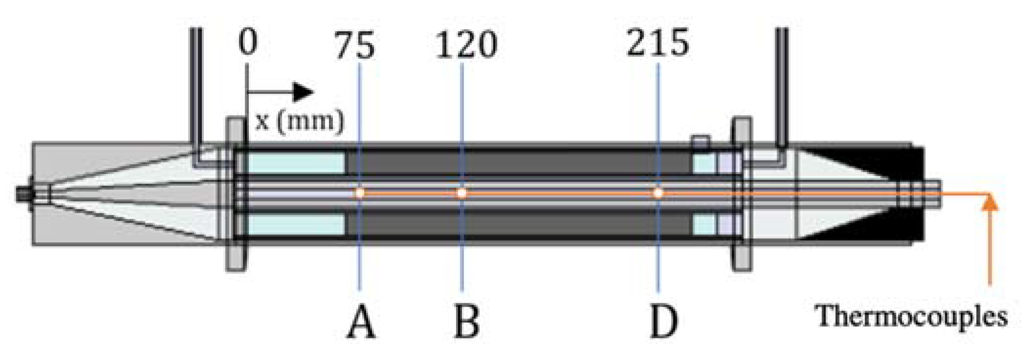
A coaxial waveguide structure was previously developed, which has no cut-off frequency for the used transverse electromagnetic (TEM) mode and is able to carry traveling microwave fields. A cross-sectional scheme of the proposed microwave reactor along the axial direction is demonstrated in Figure 1. Further information about design challenges and solutions of the coaxial traveling-wave microwave reactor can be found in the work of Eghbal Sarabi, F. et al. [20].
The outer and inner conductors of the coaxial reactor were both made of stainless steel (SS 310S) with diameters 54.8 mm and 15.7 mm, respectively. This ensures that the cut-off frequency of the system is well above 2.5 GHz. A microwave absorber was used at the end of the reactor as a terminal part to avoid any microwave leakage to the surroundings. Glass wool was used as a filling material to avoid the movement of the active bed inside the reactor. It can be observed that two Polytetrafluoroethylene (PTFE) conical bodies are used at the transition parts, where the dimensions of the coaxial cable are changed. This will smoothly change the impedance of the reactor, minimizing the reflected power. Glass wool and PTFE were selected since these are two examples of materials with negligible dielectric loss, and thus, they would not dissipate the transmitted wave energy.
To accommodate the active bed, two cylinders of quartz were used, which fitted in the PTFE conical bodies ensuring that the same position is kept throughout the experimental phase. The diameters of the outer and inner cylinder were 50 mm and 23 mm, respectively. Due to some limitations of optical fiber sensors and infrared cameras, the fixed-bed temperatures were measured with three thermocouples (type K) introduced inside the hollow inner conductor of the TMR, see Figure 1.

2.2. Microwave Active Materials

This work aims to promote further investigation of TMRs for reactive systems. Thus, it was decided to work with a material that is microwave active and can be used as catalyst support. In this regard, SiC was selected. Table 1 shows applications of SiC as catalytic support in the reactive systems, proving the potential of SiC for microwave-assisted heterogeneous catalytic technologies.
In this work, two different types of SiC were used to build microwave active beds inside the TMR. One bed was composed of irregular pieces of α-SiC with a length of 210 mm, for which 109.25 g were necessary. Considering the bulk density of α-SiC, the porosity of the porous medium was 0.897. The second bed made of cylindrical extrudes of β-SiC (5 × 5 mm) was built and tested. This bed was approximately 160 mm long, it was filled with 164 g of material. The porosity of the bed was calculated to be 0.78. Both active beds were excited with a 60 W of microwave power input. The same characteristics were used to develop the mathematical model.
Microwave power was delivered to the TMR via solid-state microwave generator (SAIREM, Lyon, France) with a maximum microwave power of 200 W. The length of the thermocouples dictated the three measuring points (see Figure 2, points A, B, and D), which values would be used to prove the efficiency of the computer model. Each experiment was repeated three times and let run until apparent steady-state conditions reached. The locations of temperature measurement are shown in Figure 2.

3. Mathematical Model

The COMSOL Multiphysics® simulation environment [30] was used to solve the three-dimensional model via the finite element method (FEM). Figure 1 shows the modeled TMR configuration and its cross-sectional schematic view along the axial direction. The reaction zone, see Figure 1, is an annular space between two concentric quartz cylinders, and the accessible reactor volume is 0.395 L. The governing equations used for each physic module are described in this section.

3.1. Electromagnetic Waves

Radio-frequency module was utilized to solve the wave equation (Equation (1)), which is derived from Maxwell’s equations and general volumetric microwave power dissipation (Equation (2)) in the microwave-susceptible domains [31,32].
× μ r 1 ( × E ) k 0 2 ( ε r j σ ω ε 0 ) · E = 0
Q M W = π f ε 0 ε r E · E *
where ε r , μ r , and ε r are the relative permittivity, relative permeability, and relative dielectric loss factor of the medium, respectively. Additionally, E is the electric field vector (V/m), E* is the complex conjugate of E, and σ , k 0 , and ω stand for the electrical conductivity of the material (S/m), the wavenumber of free space (1/m), and the angular frequency (1/s), respectively.
The impedance boundary condition (IBC) was used on the interface of the inner and outer conductor with any other different domain. IBC describes the behavior of reflective materials with a small penetration of the electric field inside the material of the boundary. It is especially useful to describe the divergence from the perfect electric conductor (PEC) boundary (everything is reflected) due to the roughness and surface defects of the material [33]. Coaxial type of ports was assigned as boundary conditions at the inlet and outlet of the reactor, see Figure 1.

3.2. Heat Transfer

The heat transfer model is applied to the whole domain of the TMR, including the porous microwave-susceptible packed-bed. A general heat transfer equation (see Equation (3)) includes the conversion of the microwave power into thermal energy ( Q M W ) and the thermal losses to the ambient via outer surfaces of the reactor. Q M W (Equation (2)) refers to the heat generation in the system. In this case, it will only be present in the microwave-susceptible material domain, e.g., catalysts and/or catalyst supports, and in the microwave absorber domain, e.g., carbon-loaded PTFE.
The heat transfer in the porous medium is modified with the addition of effective heat conductivity, k e f f , and effective heat capacity, C p ,   e f f , to the Equation (3). The effective heat capacity and effective thermal conductivity of a porous medium have been computed as volume average, see Equations (3a) and (3b) [32,34].
( ρ C p ) T t + ρ C p u · T ( k · T ) = Q M W    
( ρ C p ) e f f = ( 1 ϕ ) · ρ s C p , s + ϕ ρ f C p f      
k e f f = ( 1 ϕ ) k s + ϕ k f      
where u is the velocity vector field of the fluid, ϕ is the porosity of the medium, and T is the temperature. Subscript f refers to the fluid and s to the solid part of the domain. Additionally, no fluid flow has been simulated, therefore, the convective term will be null.
Due to the natural convection on the external surfaces of the reactor, these boundaries were assigned as convective heat flux with a heat transfer coefficient set to 10 W/m2/K. The initial conditions of the whole system were set to 20 °C as this was the lab temperature.
First, the electromagnetic model was validated by comparing the results of the mathematical model with the scattering parameters of the TMR. Then, the complete model has been validated by comparing the results with the heating experiments with catalytic active beds made of regular pieces of α-SiC or regular extrudes of β-SiC (5 × 5 mm).

4. Results and Discussions

4.1. Validation of the Electromagnetic Model

In order to validate the electromagnetic model, the TMR scattering parameters were measured with a network analyzer (Agilent Technologies E5071C, Santa Clara, CA, USA), which functions in the frequency range of 300 kHz to 14 GHz. The validation procedure was performed by using different configurations that could be replicated and measured in the lab. The three different tested configurations are as follows:
  • TMR without the microwave absorber or quartz tubes;
  • TMR with external quartz tube, but no microwave absorber end (terminal part);
  • TMR with microwave absorber and inner and outer quartz tubes.
As seen in Table 2, the experimental and simulated scattering parameter (S11) values are in good agreement. It must be considered that the sensitivity of the experimental values with respect to the environment in which the measurements were carried out is considerable. It was not considered necessary to refine the dielectric properties of the materials in the simulation to match the network analyzer values. This matching shows that the behavior of the electromagnetic model agrees well with the physical setup, which results in the validation of the model from the electromagnetic point of view.

4.2. Validation of the Electromagnetic Heating Model

The complete model, including Maxwell’s equations, the energy balance, and the generation of heat by the dissipation of the microwave energy, was compared to the values obtained by exciting the two different active materials with a solid-state microwave generator.
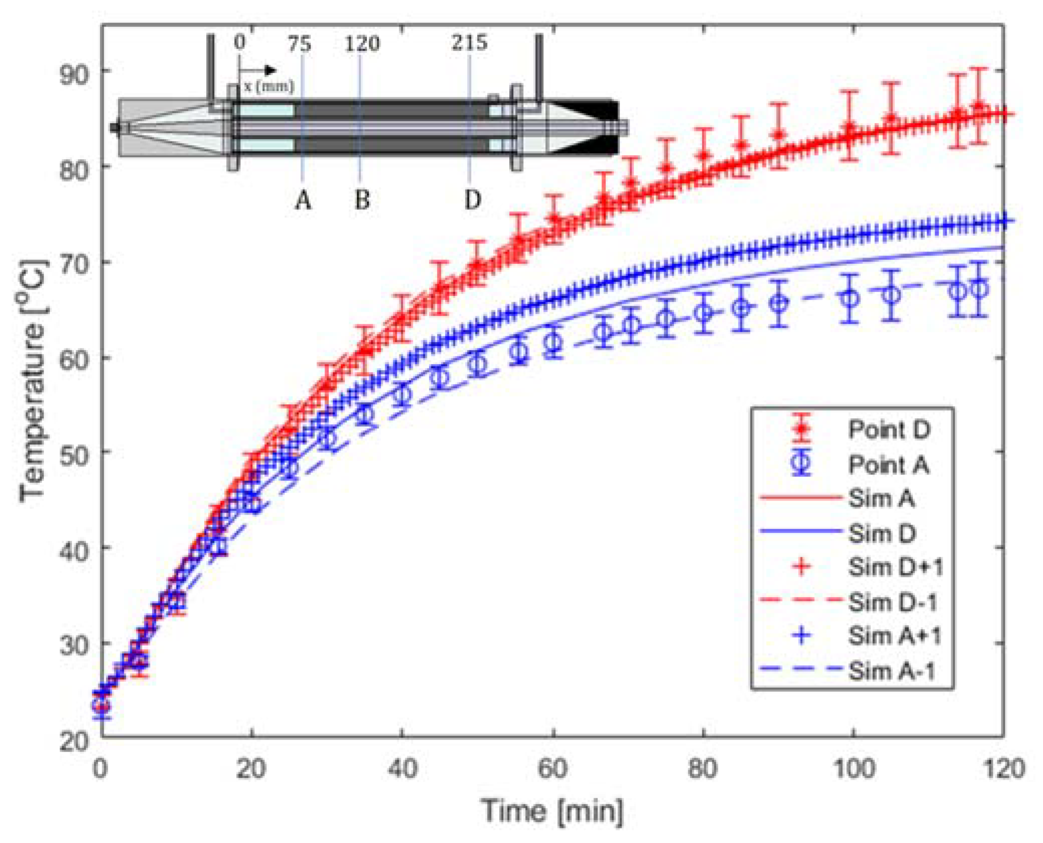
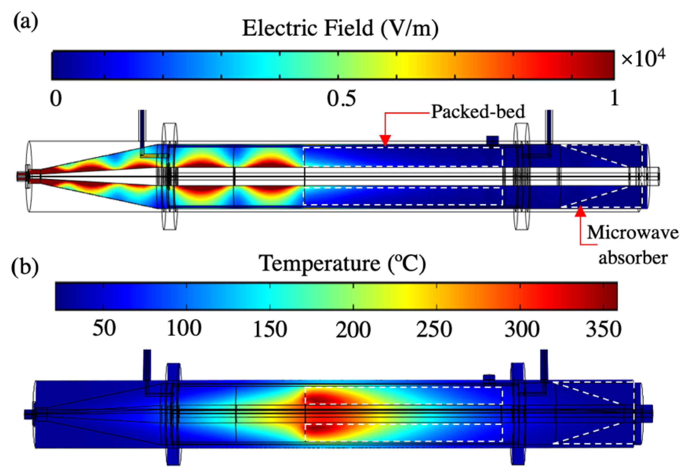
Figure 3 shows the simulated electromagnetic field distribution and corresponding heat distribution in the TMR loaded with crushed α-SiC foam under a 60 W microwave power irradiation. After 120 min of irradiation, the computed temperature field distribution for the crashed foam SiC packed-bed showed a homogeneous temperature distribution, see Figure 3b. This is due to the minor changes that the packed-bed provokes the electric field intensity.
The simulated temperature data were compared with the experimental results, see Figure 4. It is clear that the simulated temperature data fits quite well with the experimental data at the 120 min (see Table 3). After 120 min of irradiation, the maximum temperature was observed at the end of the packed-bed ca. 85 °C (point D), and the temperature at the beginning of the packed-bed reached up to 70 °C (point A). In order to compare the simulated temperature results with the experimental one, additional temperature measurement points of thermocouples with a 1 cm tolerance in each direction was included in the simulation, see Figure 4. In this regard, we did not observe a significant temperature difference at Point D. However, the temperature difference can be seen clearly in the beginning part of the packed-bed, cool side. The temperature data at point D is overestimated by the measured ones. There are a variety of errors that could have an influence on the real position of the thermocouple, such as bending of the thermocouple inside the inner conductor of the reactor. The average percentage relative deviations, APRD, of the model, are presented in Table 3.
It is reaffirmed that this packed-bed does not dissipate the electromagnetic energy efficiently. Thus, the forward microwave power reaches up to the microwave absorber, where it is dissipated, as concluded from the experimental data. This kind of packed-bed could still be appropriate for microwave heating of reaction systems, more likely the reactions take place at mild temperatures.
On the other hand, the model for the β-SiC packed-bed predicted a very low value of the electric field in the microwave absorber domain, meaning that the microwave active packed-bed could dissipate more power, see Figure 5b.
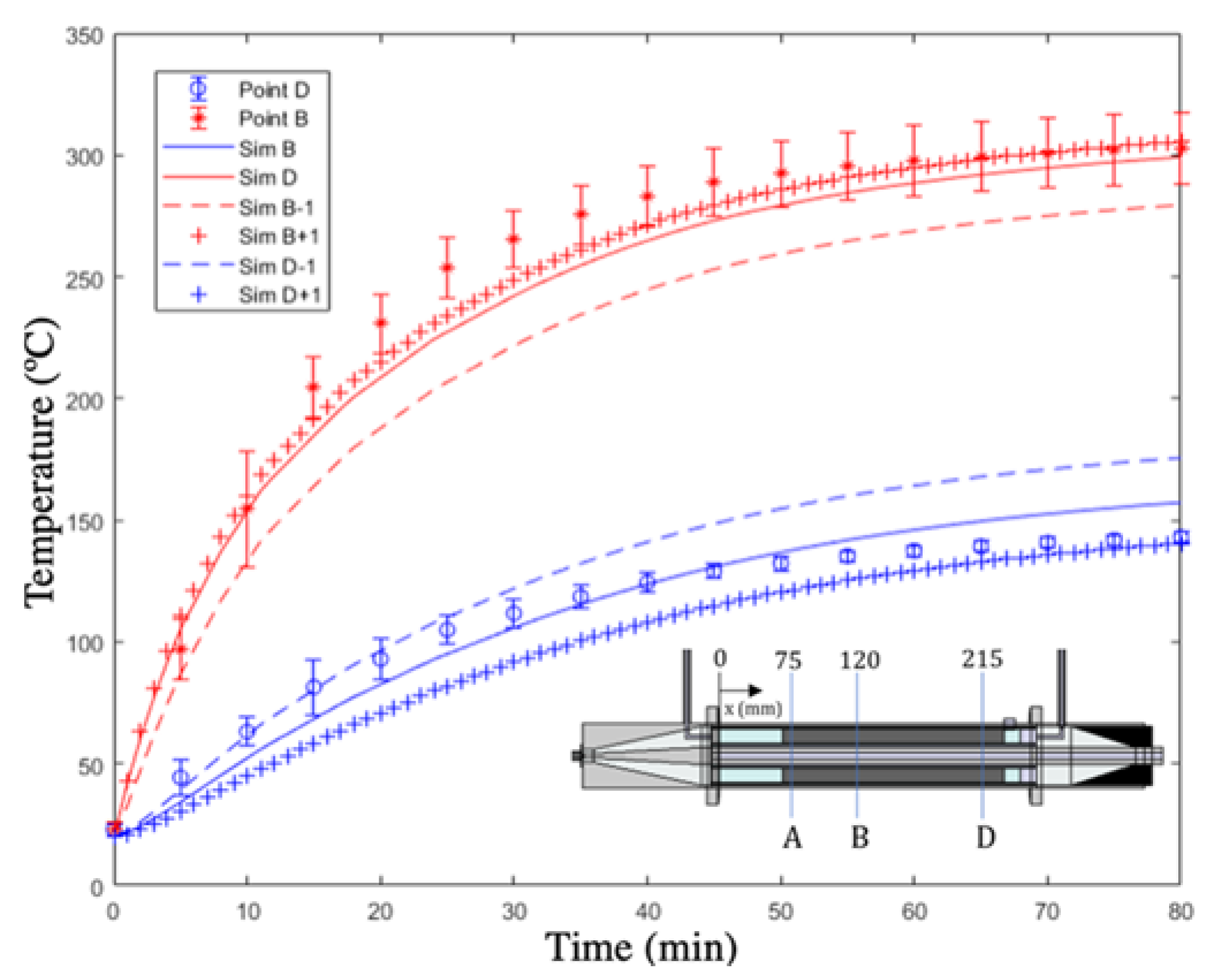
Once again, the predicted temperature is in good agreement with the experimental values from the readings of the thermocouples, as seen in Figure 6. Additionally, it is observed that the temperatures reached are comparable to values seen in the literature with monomode and multimode microwave cavities. However, in this case, the specific power input is much lower [10]. The high temperatures of the β-SiC packed-bed when exposed to only 60 W of microwave power present promising results, indicating the potential of this technology.
The fit between the model and the heating experiments can be seen in Table 3, in form of the average percent relative deviation (APRD). With all values lower than 10%, the model can be considered useful and validated.

5. Conclusions

The present work shows that it is possible to reliably model the heating characteristics of a microwave-absorbing solid material inside a Traveling-wave Microwave Reactor at these time scales. The model can be utilized as a tool in the development and design of this type of reactor. Using it as a starting point, the reactor dimensions and materials can be optimized to obtain not only higher temperatures inside the bed but also more homogeneous temperature distribution. The results of this study also prove that it is possible to use computer modeling techniques to overcome the limitations of the temperature measurements in the TMRs. Furthermore, the experiments described in the paper confirm that the TMR configuration can heat a microwave-absorbing solid catalyst efficiently.

Author Contributions

This study was conducted through the contributions of all authors. Conceptualization, investigation, validation, software, A.M.G.; writing—original draft preparation, A.M.G.; writing—review and editing, H.N. and A.S.; visualization, A.M.G. and H.N.; supervision, H.N. and A.S.; funding acquisition, A.S. All authors have read and agreed to the published version of the manuscript.

Funding

This work was supported by the European Union’s Horizon 2020 Research and Innovation Programme (ADREM project—Grant Agreement No. 680777) and the APC has been waived by the journal.

Data Availability Statement

The data presented in this study are available on request from the corresponding author.

Acknowledgments

This work was supported by the European Union’s Horizon 2020 Research and Innovation Programme (ADREM project—Grant Agreement No. 680777).

Conflicts of Interest

The authors declare no conflict of interest.

References

  1. Horváth, I.T. Introduction: Sustainable Chemistry. Chem. Rev. 2018, 118, 369–371. [Google Scholar] [CrossRef] [Green Version]
  2. Cséfalvay, E.; Horváth, I.T. Sustainability Assessment of Renewable Energy in the United States, Canada, the European Union, China, and the Russian Federation. ACS Sustain. Chem. Eng. 2018, 6, 8868–8874. [Google Scholar] [CrossRef]
  3. Náray-Szabó, G.; Mika, L.T. Conservative evolution and industrial metabolism in Green Chemistry. Green Chem. 2018, 20, 2171–2191. [Google Scholar] [CrossRef] [Green Version]
  4. Stankiewicz, A.I.; Nigar, H. Beyond electrolysis: Old challenges and new concepts of electricity-driven chemical reactors. React. Chem. Eng. 2020, 5, 1005–1016. [Google Scholar] [CrossRef]
  5. Tang, J.; Hong, Y.K.; Inanoglu, S.; Liu, F. Microwave pasteurization for ready-to-eat meals. Curr. Opin. Food Sci. 2018, 23, 133–141. [Google Scholar] [CrossRef]
  6. Feng, H.; Yin, Y.; Tang, J. Microwave Drying of Food and Agricultural Materials: Basics and Heat and Mass Transfer Modeling. Food Eng. Rev. 2012, 4, 89–106. [Google Scholar] [CrossRef]
  7. Onwude, D.I.; Hashim, N.; Abdan, K.; Janius, R.; Chen, G.; Kumar, C. Modelling of coupled heat and mass transfer for combined infrared and hot-air drying of sweet potato. J. Food Eng. 2018, 228, 12–24. [Google Scholar] [CrossRef]
  8. Palma, V.; Barba, D.; Cortese, M.; Martino, M.; Renda, S.; Meloni, E. Microwaves and Heterogeneous Catalysis: A Review on Selected Catalytic Processes. Catalysts 2020, 10, 246. [Google Scholar] [CrossRef] [Green Version]
  9. Julian, I.; Pedersen, C.M.; Achkasov, K.; Hueso, J.L.; Hellstern, H.L.; Silva, H.; Mallada, R.; Davis, Z.J.; Santamaria, J. Overcoming Stability Problems in Microwave-Assisted Heterogeneous Catalytic Processes Affected by Catalyst Coking. Catalysts 2019, 9, 867. [Google Scholar] [CrossRef] [Green Version]
  10. Zhang, F.; Song, Z.; Zhu, J.; Liu, L.; Sun, J.; Zhao, X.; Mao, Y.; Wang, W. Process of CH4-CO2 reforming over Fe/SiC catalyst under microwave irradiation. Sci. Total Environ. 2018, 639, 1148–1155. [Google Scholar] [CrossRef]
  11. Li, L.; Chen, J.; Yan, K.; Qin, X.; Feng, T.; Wang, J.; Wang, F.; Song, Z. Methane dry reforming with microwave heating over carbon-based catalyst obtained by agriculture residues pyrolysis. J. CO2 Util. 2018, 28, 41–49. [Google Scholar] [CrossRef]
  12. Li, L.; Yang, Z.; Chen, J.; Qin, X.; Jiang, X.; Wang, F.; Song, Z.; Ma, C. Performance of bio-char and energy analysis on CH4 combined reforming by CO2 and H2O into syngas production with assistance of microwave. Fuel 2018, 215, 655–664. [Google Scholar] [CrossRef]
  13. Durka, T. Microwave Effects in Heterogeneous Catalysis: Application to Gas-Solid Reactions for Hydrogen Production. Ph.D. Thesis, Delft University of Technology, Delft, The Netherlands, 2013. [Google Scholar]
  14. de Dios García, I.; Stankiewicz, A.; Nigar, H. Syngas production via microwave-assisted dry reforming of methane. Catal. Today 2021, 362, 72–80. [Google Scholar] [CrossRef]
  15. Nigar, H.; Navascués, N.; De La Iglesia, O.; Mallada, R.; Santamaria, J. Removal of VOCs at trace concentration levels from humid air by Microwave Swing Adsorption, kinetics and proper sorbent selection. Sep. Purif. Technol. 2015, 151, 193–200. [Google Scholar] [CrossRef]
  16. Nigar, H.; Julián, I.; Mallada, R.; Santamaría, J. Microwave-Assisted Catalytic Combustion for the Efficient Continuous Cleaning of VOC-Containing Air Streams. Environ. Sci. Technol. 2018, 52, 5892–5901. [Google Scholar] [CrossRef]
  17. Julian, I.; Ramirez, H.; Hueso, J.L.; Mallada, R.; Santamaria, J. Non-oxidative methane conversion in microwave-assisted structured reactors. Chem. Eng. J. 2019, 377, 119764. [Google Scholar] [CrossRef]
  18. Korkakaki, E.; Walspurger, S.; Overwater, K.; Nigar, H.; Julian, I.; Stefanidis, G.D.; Tharakaraman, S.S.; Jurković, D.L. Adaptable Reactors for Resource- and Energy-Efficient Methane Valorisation (ADREM) benchmarking modular technologies. Johns. Matthey Technol. Rev. 2020, 64, 298–306. [Google Scholar] [CrossRef]
  19. Stankiewicz, A.; Sarabi, F.E.; Baubaid, A.; Yan, P.; Nigar, H. Perspectives of Microwaves-Enhanced Heterogeneous Catalytic Gas-Phase Processes in Flow Systems. Chem. Rec. 2019, 19, 40–50. [Google Scholar] [CrossRef] [Green Version]
  20. Sarabi, F.E.; Ghorbani, M.; Stankiewicz, A.; Nigar, H. Coaxial traveling-wave microwave reactors: Design challenges and solutions. Chem. Eng. Res. Des. 2020, 153, 677–683. [Google Scholar] [CrossRef]
  21. Muley, P.D.; Henkel, C.E.; Aguilar, G.; Klasson, K.T.; Boldor, D. Ex situ thermo-catalytic upgrading of biomass pyrolysis vapors using a traveling wave microwave reactor. Appl. Energy 2016, 183, 995–1004. [Google Scholar] [CrossRef] [Green Version]
  22. Mitani, T.; Hasegawa, N.; Nakajima, R.; Shinohara, N.; Nozaki, Y.; Chikata, T.; Watanabe, T. Development of a wideband microwave reactor with a coaxial cable structure. Chem. Eng. J. 2016, 299, 209–216. [Google Scholar] [CrossRef] [Green Version]
  23. Yan, P.; Stankiewicz, A.I.; Sarabi, F.E.; Nigar, H. Microwave heating in heterogeneous catalysis: Modelling and design of rectangular traveling-wave microwave reactor. Chem. Eng. Sci. 2021, 232, 116383. [Google Scholar] [CrossRef]
  24. Palma, V.; Meloni, E. Microwave susceptible catalytic diesel particulate filter. Chem. Eng. Trans. 2016, 52, 445–450. [Google Scholar]
  25. Sun, J.; Xia, G.; Yang, W.; Hu, Y.; Shen, W. Microwave-assisted method to degrade phenol using persulfate or hydrogen peroxide catalyzed by Cu-bearing silicon carbide. Water Sci. Technol. 2020, 82, 704–714. [Google Scholar] [CrossRef]
  26. Zhang, Y.; Song, Z.; Yan, Y.; Zhao, X.; Sun, J.; Mao, Y.; Wang, W. Performance of Fe/SiC catalysts for cracking of toluene under microwave irradiation. Int. J. Hydrogen Energy 2018, 43, 7227–7236. [Google Scholar] [CrossRef]
  27. Ledoux, M.J.; Pham-Huu, C.; Keller, N.; Nougayrede, J.B.; Savin-Poncet, S.; Bousquet, J. Silicon Carbide Supported NiS2 Catalyst for the Selective Oxidation of H2S in Claus Tail-Gas. In Studies in Surface Science and Catalysis; Elsevier: Amsterdam, The Netherlands, 2000; Volume 130 C, pp. 2891–2896. [Google Scholar]
  28. Díaz, J.A.; Calvo-Serrano, M.; De La Osa, A.R.; García-Minguillán, A.M.; Romero, A.; Giroir-Fendler, A.; Valverde, J.L. β-silicon carbide as a catalyst support in the Fischer–Tropsch synthesis: Influence of the modification of the support by a pore agent and acidic treatment. Appl. Catal. A Gen. 2014, 475, 82–89. [Google Scholar] [CrossRef]
  29. Ivanova, S.; Vanhaecke, E.; Louis, B.; Libs, S.; LeDoux, M.-J.; Rigolet, S.; Marichal, C.; Pham, C.; Luck, F.; Pham-Huu, C. Efficient Synthesis of Dimethyl Ether over HZSM-5 Supported on Medium-Surface-Area β-SiC Foam. ChemSusChem 2008, 1, 851–857. [Google Scholar] [CrossRef] [PubMed]
  30. COMSOL Multiphysics® v. 5.4. www.comsol.com; COMSOL AB: Stockholm, Sweden, 2018.
  31. RF Module User’s Guide; COMSOL Multiphysics® v. 5.4.; COMSOL AB: Stockholm, Sweden, 2018; pp. 84–92.
  32. Nigar, H.; Sturm, G.S.J.; Garcia-Baños, B.; Peñaranda-Foix, F.L.; Catalá-Civera, J.M.; Mallada, R.; Stankiewicz, A.; Santamaría, J. Numerical analysis of microwave heating cavity: Combining electromagnetic energy, heat transfer and fluid dynamics for a NaY zeolite fixed-bed. Appl. Therm. Eng. 2019, 155, 226–238. [Google Scholar] [CrossRef]
  33. Mohsen, A. On the impedance boundary condition. Appl. Math. Model. 1982, 6, 405–407. [Google Scholar] [CrossRef]
  34. Heat Transfer Module User’s Guide; COMSOL Multiphysics® v. 5.4.; COMSOL AB: Stockholm, Sweden, 2018; pp. 168–170.
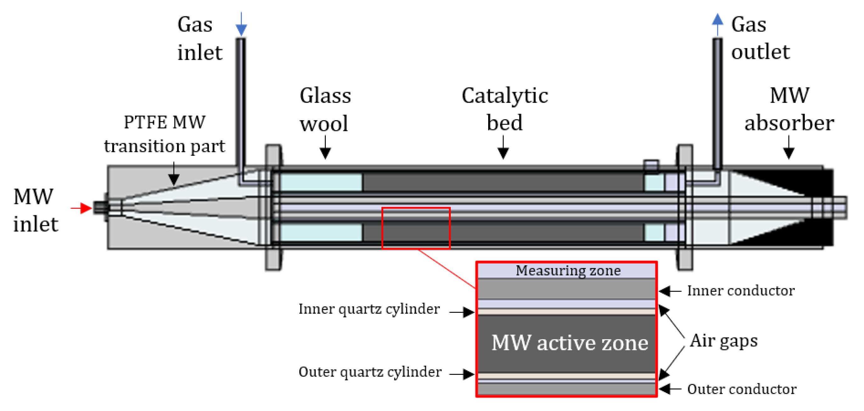
Figure 1. Representation of the axial section of the in-house built traveling-wave microwave reactors (TMR).
Catalysts 11 00369 g001
Figure 2. Locations of the thermocouples for the temperature measurement inside the inner conductor.
Catalysts 11 00369 g002
Figure 3. (a) Temperature and (b) Electric field distribution after 120 min in the reactor loaded with crushed α-SiC foam under 60 W microwave power input.
Catalysts 11 00369 g003
Figure 4. Comparison of the experimental and simulated transient temperatures in the crushed α-SiC foam under 60 W microwave power input (A and D are the locations of the thermocouples).
Catalysts 11 00369 g004
Figure 5. (a) Temperature and (b) Electric field distribution after 80 min in the reactor loaded with β-SiC under 60 W microwave power input.
Catalysts 11 00369 g005
Figure 6. Comparison of the experimental and simulated transient temperatures in the β-SiC loaded packed-bed under 60 W microwave power input (B and D are the locations of the thermocouples).
Catalysts 11 00369 g006
Table 1. Applications of SiC as catalytic support in reaction systems.
CatalystReactionMicrowave HeatedRef.
FeDry reforming of methaneYes[10]
NiDry reforming of methaneYes[14]
Mo-ZSM-5Non-oxidative methane conversionYes[17]
CuFe2O4Catalytic oxidation of diesel sootYes[24]
CuPhenol degradationYes[25]
FeCracking of tolueneYes[26]
NiS2H2S oxidationNo[27]
CoFischer-TropschNo[28]
HZSM-5Methanol dehydrationNo[29]
Table 2. Values of the scattering parameter S11 for the validation of the electromagnetic model.
Model NumberExperimental (S11)Simulated (S11)
dBPower reflection (%)dBPower reflection (%)
1−8.1715.24−6.7820.99
2−3.9340.46−2.7453.21
3−18.461.43−14.453.59
Table 3. Average percent relative deviation (APRD) between simulated values of temperature and thermocouple readings from heating experiments.
α-SiCβ-SiC
Simulated PointAPRD (%)Simulated PointAPRD (%)
A2.02B4.52
D2.34D8.78
Publisher’s Note: MDPI stays neutral with regard to jurisdictional claims in published maps and institutional affiliations.