Abstract
Metal–organic frameworks (MOFs) are used in catalysis due to their high specific surface area and porous structure. The dispersed active sites and limited reaction space that render MOFs have the potential for highly selective electrocatalytic CO2 reduction reaction (ECO2RR). Meanwhile, formic acid (HCOOH) is attracting attention as a liquid product with high economic benefits. This review summarizes the MOFs and their derivatives applied for ECO2RR into HCOOH products. The preparation methods of MOFs as electrocatalysts and their unique advantages are discussed. A series of MOFs and MOF derivatives obtained by electrochemical reduction or carbonization processes are highlighted, including metal nanomaterials, carbon-based nanocomposites, single-atom catalysts, and bimetallic nanocomposites. Depending on the MOF building units (metal ions and organic linkers) and the reaction conditions of derivatization, MOF-based catalysts exhibit rich diversity and controllable modulation of catalytic performance. Finally, the challenges encountered at this stage and the future research directions of MOF-based catalysts are proposed.
1. Introduction
The increasing severity of the global climate problem caused by CO2, the main component of greenhouse gases, has stimulated plenty of research and development projects on various ways to convert CO2 to achieve sustainable development. A conscious shift is taking place that CO2 is no longer seen as a waste but as an abundant renewable C1 resource [1]. In this context, electrocatalytic CO2 reduction reaction (ECO2RR) has become a hot research topic. Compared with traditional thermochemical means, it can be carried out at normal temperature and pressure. The electricity generated by renewable energy, such as wind energy, water energy, and solar energy, replaces the toxic and expensive equivalent reducing agent, which is a promising tool for CO2 conversion [2]. The CO2 molecule contains two σ bonds and two delocalized bonds with bond energies up to 750 kJ mol−1 and possesses high thermodynamic stability and low electron affinity; thus, it is difficult to activate CO2. On the other hand, hydrogen evolution reaction (HER) becomes a competitive process kinetically, which should be avoided when ECO2RR occurs in the aqueous electrolyte. Therefore, it is very important to develop efficient catalysts to promote the conversion of CO2. The ideal electrocatalyst should have the following advantages: high-efficiency conversion at low overpotential, high selectivity toward the target product and minimum hydrogen evolution in aqueous media, high stability, abundant in nature, and low cost [3].
At present, the catalysts used in ECO2RR can be divided into the following categories: (1) typical metal-based heterogeneous catalysts, consisting of metals oxides, sulfides, alloys, etc., have high activity and conductivity, but ECO2RR often occurs on the catalyst surface, which means a low atomic utilization rate [4,5]; (2) molecular catalysts, mostly metal complexes, are usually used in homogeneous systems. They have well-defined structures containing organic ligands and metal ions, which is conducive to the establishment of theoretical models and the exploration of mechanisms, as well as further modification by organic synthesis. However, they are difficult to separate from the resultants after reaction for reuse. In recent years, the supported molecular catalysts have received much more attention. Although the atom utilization rate has been improved by anchoring the metal atom through coordination, aggregation between complexes can also lead to degradation of the atom utilization rate, stability, and catalytic performance [2]; (3) single-atom catalysts often anchor single-metal atoms to conductive carbon-based support through N, C, O, or S atoms to achieve the effect of high atom utilization rate, with high stability and activity [6]; (4) metal-free catalysts have also been developed and have obvious advantages of low price, but there is still a gap between them and the above catalysts in terms of catalytic efficiency [7].
In ECO2RR, CO2 can be converted into various energy-related small molecules through multiple proton-coupled electron transfer processes, including formic acid (HCOOH), carbon monoxide (CO), methanol (CH3OH), methane (CH4), ethanol (C2H5OH), ethylene (C2H4), etc. Among them, CO and HCOOH are more economically effective products at the present stage. As a liquid product, HCOOH is more conducive to storage and transportation and can easily generate H2 through a decomposition reaction, which has practical applications in hydrogen storage materials and fuel cells [8,9]. In addition, HCOOH is an important raw material for the preparation of various chemicals [10,11]. In recent years, HCOOH has also been applied in air separation and CO2 recognition and capture [12,13,14].
In this respect, a series of metal-based catalysts (Sn, In, Bi, Pb, and Pd) have shown suitable HCOOH selectivity [15,16]. The proposed mechanism of ECO2RR to formic acid can be divided into four main categories (Figure 1): path (1) is considered that the binding between CO2 anion radical intermediate and catalyst is so weak that the formation of HCOOH occurs via hydration of nonadsorbing CO2 anion radical intermediate [5,17]; path (2) is accompanied by metal(M)-C bonding, forming *COOH intermediate [2,18]; path (3) is involved in the formation of M-O bonds, where CO2 forms *OCHO intermediate after gaining electrons and proton [19]; path (4) is to insert CO2 into M-H bond to obtain *OCHO intermediate, and then generate HCOOH in the subsequent reduction step [2,19].
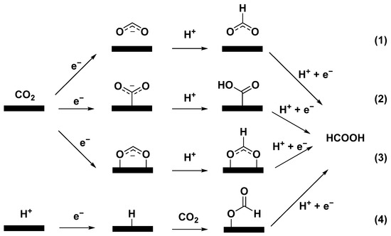
Figure 1.
Proposed reaction pathways of ECO2RR to HCOOH.
Metal–organic frameworks (MOFs) are becoming promising porous crystal materials, which are composed of metal ions or cluster nodes and organic ligands as linkers, and have a wide range of applications in numerous areas [20]. Almost all transitional and main group metals can be used for assembly with appropriate organic ligands to form functional MOFs. MOFs with custom structure, morphology, and pores can be designed and synthesized by changing metal nodes, organic linkers, or preparation conditions [21]. MOFs has the following advantages: (1) high specific surface area and ordered porous structure, which can promote the adsorption and activation of CO2 [22], making it suitable for heterogeneous catalysis; (2) the metal nodes in the MOFs structure periodically distribute, which means the effective dispersion of active sites and the increased utilization rate of metal atoms [23,24]; (3) the structure of the organic ligands used to construct MOFs can be adjusted and modified, which is conducive to regulating the electronic structure of the active site to affect the catalytic performance. The well-defined crystal structure is also conducive to the establishment of the theoretical models, so as to study the structure–activity relationship [25,26]. The above points make MOFs a promising catalyst for ECO2RR.
However, the application of MOFs as electrocatalysts is largely limited by low conductivity and inevitable mass transfer limitation [27]. At the same time, some MOFs may have poor stability during the electroreduction process due to the weak coordination bonds between metal nodes and organic ligands [28]. On the other hand, MOFs are also attractive precursors or sacrifice templates, which can yield metal (oxide) nanomaterials or metal nanocomposites containing porous carbon structures [29,30]. Compared to the pristine MOFs, these derivatives tend to have enhanced intrinsic conductivity, catalytic activity, and stability, showing promising potential in ECO2RR [31]. More importantly, MOF-derived materials may inherit the characteristics of MOFs, including high specific surface area, adjustable composition, uniform component distribution, and original morphology [32].
In this review, we are particularly concerned with the MOFs and the application as the electrocatalysts for ECO2RR into formic acid/formate. Our aim in this review article is to summarize the current electrocatalytic performance of MOFs and their derivatives, to demonstrate methods for constructing catalysts from MOFs, and to provide some insights into the future development of MOF-related catalysts.
2. Evaluation of Catalyst Performances
Here, we introduce some important metrics for catalyst evaluation so as to also facilitate a comparison between various catalysts. In fact, there will be inevitable errors in the comparison of catalysts reported by different works because the experimental conditions used are almost impossible to be completely consistent, including electrodes for loading, electrolyte, and electrolytic cell devices. In addition, all catalysts discussed in this review are summarized in Table 1, and all structures of organic linkers are illustrated in Figure 2.

Table 1.
Heterogeneous MOF and MOF-derived catalysts for ECO2RR into HCOOH in this review. The full names of the abbreviations are as following: GO (graphene oxide), TBAB (tetrabutylammonium bromide), DMF (N,N-Dimethylformamide), EMIMBF4 (1-ethyl-3-methylimidazolium tetrafluoroborate), NSs (nanosheets), MNS (MOF-derived nanosheet), NPs (nanoparticles), NC (N-doped carbon matrix), BSG (bismuth subgallate), H (HKUST-1), SOR (surface-oxygen-rich), and ZIF (zeolitic imidazolate framework). The solvent of electrolyte is water unless otherwise stated.
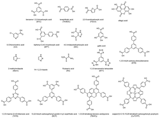
Figure 2.
Structures and abbreviations of organic linkers for constructing MOFs discussed in this review.
2.1. FE
Faraday efficiency (FE) reflects the selectivity of the current to a specific CO2 reduction product and is calculated as the ratio of the amount of charge consumed to produce a product to the total amount of charge consumed to flow through the circuit. High FE values will minimize product separation requirements and reduce the total current required for the target product yield.
2.2. Overpotential and Applied Potential
Overpotential is defined as the difference between the applied potential and the thermodynamic equilibrium potential of CO2 reduction to a certain product. Theoretically, the closer the overpotential is to 0 V, the better the catalyst performance, which means the actual voltage required to reach a certain current density and the energy consumption are lower, and the catalytic activity is higher. Since most heterogeneous catalysts discussed in this review are in aqueous systems, where thermodynamic equilibrium potentials are consistent, the applied potential is used for evaluation for convenience of introduction. In addition, the potential values below are all versus reversible hydrogen electrodes (RHEs) unless otherwise stated.
2.3. Current Density and TOF
Current density reflects the reaction rate in the ECO2RR and, to some extent, the conductivity of the catalyst. The value is the current passing through the electrode per unit area. The current density required for commercialization is generally >200 mA cm−2.
Turnover frequency (TOF) reflects the intrinsic activity of the catalyst, which is the number of moles of product transformed by the moles of catalytic active species per unit time. The higher the TOF value, the higher the activity of the catalyst. However, in the case of many heterogeneous systems, all catalysts supported are often regarded as active substances. In fact, only the catalyst on the surface plays a role, so the TOF obtained is often the minimum value, which has a large error, so it is not listed in Table 1. However, for some works requiring special explanation, we still mention this metric.
3. MOF Materials
3.1. Copper-Based MOFs
Cu is the only metal with the ability to catalyze hydrocarbon formation and is one of the most promising candidates as an ECO2RR catalyst. However, due to its ability to produce multiple products and the complex reaction pathways of CO2 reduction, the products include CO, methane, acetic acid, ethanol, and ethylene, in addition to formic acid. Copper-based catalysts are often less selective for one particular product.
In 2012, MOFs were first applied in the field of ECO2RR [24]. Copper rubeanate MOF (CR-MOF) is synthesized with rubeanic acid (RA) as the organic linker and Cu2+ as the metal node. The initial CO2 reduction potential of CR-MOF is more positive than that of Cu. At −1.2 V, −1.4 V, and −1.6 V versus the standard hydrogen electrode (vs. SHE), HCOOH accounts for more than 98% of CO2 reduction products, although the FE for CO2 reduction is only 30%. Both HCOOH selectivity and yield are much higher than that of Cu. HCOOH is believed to be easily produced under the condition of weak CO2 adsorption. Cu2+ and the structure of MOF reduce the electron density in the active center, leading to weak adsorption of CO2 at the active sites and selective generation of HCOOH. At the same time, the abundant pores in CR-MOF are speculated to restrict other reaction pathways in the active center, resulting in high HCOOH selectivity. Although the HER is still difficult to suppress, this study has preliminarily demonstrated the application potential of MOF catalysts for ECO2RR.
Cu-MOF constructed from benzene-1,3,5-tricarboxylic acid (BTC) is investigated in six electrolyte systems after mixing with graphene oxide (GO) [33]. In 0.1 M KHCO3, the catalyst has the lowest starting potential and reaches FEHCOOH of 21% at −0.1 V versus standard calomel electrode (vs. SCE). In 0.1 M tetrabutylammonium bromide/N,N-Dimethylformamide (TBAB/DMF), the highest FE for HCOOH (FEHCOOH) of 58% arrived at −0.6 V vs. SCE. GO improves the conductivity and product selectivity of the catalyst. Only FE of 38% is reached when Cu-MOF is used alone. In addition to HCOOH, a small amount of acetic acid is also produced.
Cu2(CuTCPP) nanosheets (NSs) is synthesized by Cu2(COO)4 paddle wheels connected four copper (II)-5,10,15,20-tetrakis(4-carboxyphenyl) porphyrin (CuTCPP), which possesses two-dimensional lamellar porous mesh frame structure (Figure 3a). The use of CuTCPP as an organic linker for the construction of MOF catalysts is a special case because CuTCPP also contains active sites. During the initial process of electrolysis, the current density increases gradually, and chemical recombination may occur. The changes of catalysts at −1.55 V vs. Ag/Ag+ are detected by ex situ powder X-ray diffraction (XRD) (Figure 3b), and the unstable Cu2+ carboxylate nodes may be transformed into CuO, Cu2O, and Cu4O3, which with CuTCPP synergistically promotes the reduction of CO2 to formate and acetic acid in 1 M H2O and 0.5 M 1-ethyl-3-methylimidazolium tetrafluoroborate (EMIMBF4)/CH3CN systems. The highest value of FE for HCOO− (FEHCOO−) reaches 68.4% at −1.55 V vs. Ag/Ag+, while the FE for acetate also reaches 16.8% [27].
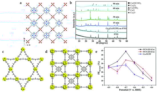
Figure 3.
(a) Crystal structure of Cu2(CuTCPP) NSs along the c axis. Red is O, blue is N, gray is C, and cyan is Cu. (b) XRD of Cu2(CuTCPP) NSs on an F-doped tin oxide (FTO) electrode with different reaction times [27]. Copyright 2019, RSC. Structural models of (c) PCN-222(Cu) and (d) PCN-224(Cu). (e) FEHCOOH in 0.5 M KHCO3 solution [34]. Copyright 2020, RSC.
In order to explore the influence of MOF catalysts with different structures on ECO2RR performance, CuTCPP is used as an organic linker with Zr6 cluster as a metal node to construct two types of porphyrin-based MOFs (PCN-222(Cu) and PCN-224(Cu)) with different internal structures (Figure 3c,d) [34]. Compared to PCN-224(Cu) with microporous interactively across rectangular channel, PCN-222(Cu) with mesoporous tubular-like channel shows higher BET surface area, better CO2 absorption, and larger pore size, which is more conducive to mass transfer. PCN-222(Cu) shows higher catalytic activity and selectivity for HCOOH at −0.7 V (Figure 3e), and the FE reaches 44.3% with a current density of 3.2 mA cm−2. On the other hand, PCN-224(Cu) has greater heat of adsorption and a higher affinity for CO2, which can promote the exposure of active sites, so it has better performance at lower potentials (−0.4–−0.6 V).
3.2. Bismuth-Based MOFs
Bi has been identified as a potential catalyst with several advantages in ECO2RR: (1) Bi has low HER activity, which is a competitive reaction to cathode potential, and inhibiting hydrogen evolution can improve energy conversion efficiency [60]; (2) Bi has low adsorption energy of *CO intermediate and strong stabilization ability of *HCOO intermediate, which is conducive to the formation of HCOOH [45]. Although the bismuth-based catalysts have been reported to have FEHCOOH higher than 90%, the low current density (<10 mA cm−2) has hindered industrial applications [61]. Compared to bulk Bi, bismuth-based MOF-derived catalysts tend to have higher stability and conductivity and show excellent catalytic activity, which is due to the large surface area and abundant unsaturated active sites.
Some Bi-carboxylate MOFs will be decomposed in KHCO3 electrolyte and in situ converted into Bi2O2CO3, which is the active material for ECO2RR (Figure 4a). By XRD, obvious Bi2O2CO3 correlated peaks can be observed after electrolysis or immersion of Bi-BTB in KHCO3 electrolyte (Figure 4b). Bi-BTB MOF-derived Bi2O2CO3 shows suitable catalytic activity and product selectivity and reaches a FEHCOO− of 96.1% with a current density of 13.2 mA cm−2 at −0.699 V. At the same time, it has excellent structural stability with no obvious drop of current density occurs in 48 h electrolysis, and FEHCOO− is maintained above 93%. Another Bi-MOF with 1,3,5-triazine-2,4,6-tribenzoic acid (TATB) as the organic linker can undergo similar in situ transformation, suggesting that the effect of HCO3− electrolyte-mediated dissociation is universal [35].
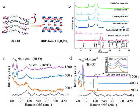
Figure 4.
(a) Proposed mechanism for the formation of MOF-derived Bi2O2CO3. (b) XRD patterns of carbon paper electrode (green), Bi–BTB/carbon paper electrode before electrolysis (sky blue), after 0.5 h electrolysis (steel blue) and after 10 h electrolysis (dark blue), and Bi–BTB soaked in KHCO3 after 15 min (salmon) and after 20 h (firebrick) [35]. Copyright 2020, RSC. In situ Raman spectra of Bi-BTC during the catalytic process under various potentials: (c) −0.5 V and (d) −0.7 V at 0.1 M KHCO3 [36]. Copyright 2022, Elsevier.
In addition, the electrolyte-mediated dissociation product Bi2O2CO3 undergoes further transformation under the condition of electroreduction. Bi-BTC MOF observation by in situ Raman spectra shows that Bi2O2CO3 gradually transforms into Bi and Bi2O2.5 at −0.7 V (Figure 4c,d), in which the rich Bi/Bi-O interface is the active site that can promote the reduction of the free-energy barrier of *HCOO intermediate formation. In the flow cell, a maximum FEHCOOH of 92% is achieved at −0.64 V with a current density of 150 mA cm−2 in 1.0 M KOH, and a long time stability of 30 h is achieved with FEHCOOH above 80% in the H-cell [36]. Although it can be seen by XRD that MOF has been completely transformed into Bi and Bi2O2.5 mixture after reaction, the utilization of in situ skills is still an effective way to explore the intrinsic catalytic properties of such MOF-derived catalysts.
There are also some interesting findings in the study of Bi-BTC MOF (CAU-17). Through the operando X-ray absorption fine structure (XAFS) analysis (Figure 5a,b), it is found that CAU-17 keeps close to Bi3+ for more than 90 min at −0.9 V, while 2D Bi NSs, Bi2O3 nanotube completely transformed into Bi0 within 1h. The MOF structure is thought to play a key role in maintaining Bi in the +3 oxidation state at the reduction potential, which is conducive to the long-term ECO2RR. CAU-17 reaches FEHCOOH of 92.2% at −0.9 V and maintains the product selectivity along with current density almost unchanged for 30 h (Figure 5c,d) [16].
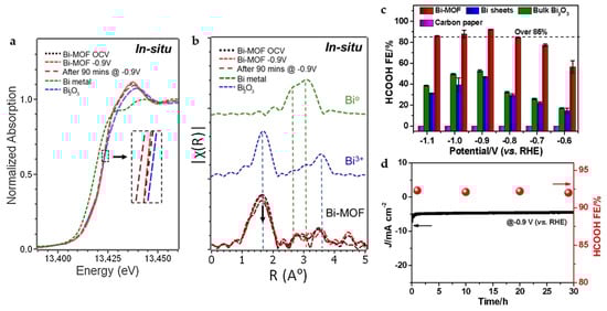
Figure 5.
(a) X-ray absorption near-edge structure (XANES) and (b) Fourier transform of extended X-ray absorption structure (FT-EXAFS) spectra under in situ electrochemical CO2 reduction conditions for Bi-MOF along with those for Bi metal and Bi2O3 as reference standards. (c) FEHCOOH of CAU-17, Bi sheets, bulk Bi2O3, and carbon paper electrodes in CO2-saturated 0.1 M KHCO3 solution. (d) Current density and FEHCOOH of CAU-17 during long-term electrolysis at –0.9 V [16]. Copyright 2020, Elsevier.
Replacing terephthalic acid (TA) derived from fossil fuels with 2,5-furandicarboxylic acid (FDCA) derived from biomass platform molecule 5-hydroxymethylfurfural (HMF) as the organic linker of MOFs is a strategy with economic and environmental effects (Figure 6a). The Bi-FDCA MOF also reaches a high FEHCOOH of 95.1% with a current density of 19.6 mA cm−2 at −1.2 V. Interestingly, FDCA can be obtained from the catalytic oxidation reaction of HMF in the anode, which effectively establishes the coupling system of anode and cathode [37].
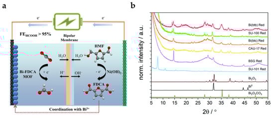
Figure 6.
(a) Diagrammatic sketch for coupling system of ECO2RR in cathode and oxidation reaction of HMF in anode [37]. Copyright 2022, Wiley-VCH. (b) Grazing incidence XRD data collected using Co Kα radiation (λ = 1.79 Å) on coordination polymers (CPs) deposited on glassy carbon electrodes after reduction for 30 min at −0.97 V. The diffraction patterns are compared with calculated patterns for Bi2O3, Bi, and Bi2O2CO3 [38]. Copyright 2021, RSC.
Lock et al. summarized Bi coordination polymers (CPs) with different organic linkers, including CAU-17, dense Bi-BTC, Bi-BTB, SU-100 (BiBPT), SU-101 (Bi-MOF with ellagic acid as the organic linker), and bismuth subgallate (BSG) [38]. The stability of CPs precursors is particularly important for their intrinsic catalytic activities. As XRD patterns shown in Figure 6b, most CPs undergo solvent-assisted linker exchange (SALE) after electrochemical reduction in HCO3− electrolyte and transform into the active species Bi2O2CO3, which is similar with the electrolyte-mediated dissociation process mentioned above. Only the most stable SU-101 is not found to undergo structural transformation, which is accompanied by low catalytic activity. At −0.97 V, SU-100 possesses the highest catalytic activity, while Bi-BTB shows the highest formate selectivity. Unfortunately, except for SU-101, no rule has been found between the porosity and local coordination of different MOFs and catalytic activity, which needs to be further explored.
3.3. Indium-Based MOFs
In has attracted more attention as a catalyst for ECO2RR to formate due to its low toxicity and environmentally friendly properties. However, the low FE and poor stability of indium-based electrocatalysts seriously hinder their practical application [55]. Compared with In catalysts, In-terephthalic acid (In-BDC) MOF catalysts show higher formate selectivity, faster reaction kinetics, more active sites and higher TOF [39]. In-BDC performs a maximum FEHCOO− of 88% at −0.669 V. In addition, unlike the Bi-carboxylate MOFs described above, SALE process is not observed on In-BDC in KHCO3 electrolyte for long-term electrolysis. The Raman and In 3d XPS spectra (Figure 7a,b) indicate that the morphology and metal valence of In-BDC do not change after electrolysis, showing suitable stability of the catalyst.
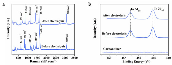
Figure 7.
(a) Raman spectra of the In-BDC catalyst before and after electrolysis. (b) In 3d XPS spectra of the In-BDC catalyst before and after electrolysis [39]. Copyright 2020, ACS.
3.4. Tin-Based MOFs
New active sites can be introduced into MOFs by means of metal nodes exchange. Sn is successfully doped into zeolitic imidazolate framework-8 (ZIF-8) by ion-exchange method (Figure 8a). The presence of Sn nodes further improves the CO2 adsorption capacity of the material, and the combination with MOF shows a larger physical and electrochemical active surface area, as well as easy charge transfer, thus showing a better catalytic activity and product selectivity. It exhibits a FEHCOO− of 74% and current density of 27 mA cm−2 at −1.1 V [23].
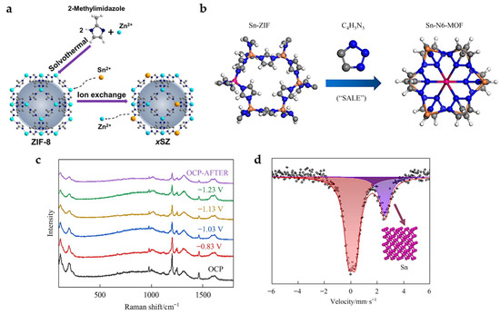
Figure 8.
(a) Schematic illustration showing the preparation of Sn-doped ZIF-8 catalysts [23]. Copyright 2020, Wiley-VCH. (b) Diagram of the synthetic procedures for Sn-N6-MOF. (c) The in situ Raman spectra measured with varying the applied potential in CO2-saturated 0.5 M KHCO3 electrolyte. (d) Room temperature 119Sn Mössbauer spectra acquired after maintained at −1.23 V in CO2-saturated 0.5 M KHCO3 electrolyte for 1 h [40]. Copyright 2022, Elsevier.
In addition, organic ligands can also be exchanged. The Sn-doped ZIF-8 is successfully converted into 2% Sn-N6-MOF with six N coordination by SALE method in 1H-1,2,3-triazole (Figure 8b). In situ Raman spectra (Figure 8c) show that the characteristic Raman peaks attributed to C-N (1000–1400 cm−1), C=C, C=N (1400–1600 cm−1) and Sn (Zn)-N (197 cm−1) gradually weakens with the increase in the applied potential from −0.83 to −1.23 V, suggesting the possible structural reconstruction of the 2% Sn-N6-MOF catalyst and loss of organic ligands. Room temperature 119Sn Mössbauer spectra (Figure 8d) further prove that the MOF structure recombines during electrolysis with Sn nanoclusters formed as the real active sites. The FEHCOOH of 85% with a current density of 23 mA cm−2 is achieved at −1.23 V [40].
3.5. Aluminum-Based MOFs
In addition to the above metals, Al also has a certain catalytic capacity for HCOOH production. Although the HCOOH selectivity is low, some interesting results have been obtained when combining Al with MOF. An Al-MOF constructed by BDC has been reported for ECO2RR [41]. The limited reaction environment in the MOF is conducive to the stable electrochemical process for the generation of Al0 active centers, which are usually readily oxidized to Al3+ in air. Compared with Al(OH)3, the structure of MOF changes the reaction environment, leading to the occurrence of different reaction paths. In addition to the inherent catalytic activity of the original HCOOH formation, the ability to produce CO is also obtained, although the FEs for both products are low (19% for HCOOH and 21% for CO at −1.1 V).
4. MOF-Derived Metal Nanomaterials
In situ electrochemical reduction is a mild and effective reduction method. For some unstable MOFs, the pretreatment process of electrochemical reduction is often accompanied by the reduction of metal ions and spontaneous aggregation to form metal nanomaterials, while the organic ligands or linkers are dissolved in the electrolyte. Compared to MOFs connected through relatively weak coordination bonds, metal nanoparticles connected by metallic bonds are significantly more conductive and stable, which effectively improves the catalyst activity and stability in ECO2RR. At the same time, compared with reducing agents, electrochemical reduction often retains some M-O species or organic ligands on the surface, which has an important impact on catalytic activity and stability. The structure of the MOF precursor also has an important impact on the morphology of the derived catalyst and the corresponding ECO2RR performance.
4.1. Copper-Based Nanomaterials
The electrocatalytic activity of Cu catalysts can be significantly enhanced by reducing the particle size, especially in the particle size range of less than 10 nm. In addition, electrochemically reduced Cu nanoparticles (NPs) from copper oxide appear to be particularly suitable for ECO2RR and have been shown to be superior to both polycrystalline Cu and hydrogen-reduced Cu from copper oxide at high temperatures. A solvothermal deposition in the MOF method is adopted to deposit Cu2+ in Zr-MOF (NU-1000). Cu NPs are further formed in electrochemical reduction, while the size of NPs is effectively limited by the pore size of MOF (Figure 9a), leading to a maximum FEHCOO− of 28% at −0.82 V in 0.1 M KClO4 electrolyte [42].
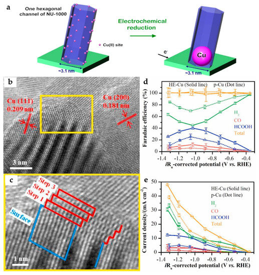
Figure 9.
(a) Schematic representation of the electrochemical reduction of Cu2+ to generate metallic Cu NPs [42]. Copyright 2017, ACS. (b) The HRTEM images of the HE-Cu and (c) stepped Cu (211) surface of the selected area. (d) Faradaic efficiency and (e) current density of the ECO2RR products for the HE-Cu and p-Cu electrodes in CO2-saturated 0.1 M KHCO3 solution [43]. Copyright 2021, Elsevier.
By in situ electroreduction, the HKUST-1-covered Cu foam electrode is transformed into a HE-Cu electrode with the morphology of NSs. The step-like structure can be observed by high-resolution transmission electron microscopy (HRTEM) images (Figure 9b,c), which is considered to be a Cu (211) surface. According to the DFT calculations, the stepped (211) surface of the Cu catalyst is more favorable to the formation of HCOOH than the stepped (111) and stepped (200) surfaces. Moreover, it has a suitable binding ability with *CO, being conducive to a further reduction to *COH/*CHO intermediates, followed by producing C2 products. Compared with the p-Cu without the stepped (211) surface, it has higher catalytic activity and HCOOH selectivity (Figure 9d,e), reaching a FEHCOOH of 40.1% at −1.03 V, as well as the highest FEs for C2H4 and C2H6 of 2.93% and 2.58%, respectively at −1.19 V [43].
4.2. Bismuth-Based Nanomaterials
As mentioned above, the SALE process will occur in the HCO3− electrolyte for Bi-carboxylate MOFs, which then derive into Bi2O2CO3. After further electrochemical reduction process, the Bi nanomaterial is obtained. In this regard, CAU-17 will derive into Bi2O2CO3 NSs in the HCO3− electrolyte, and the thickness of NSs is affected by the concentration of HCO3−, which influence the thickness of Bi NSs obtained in the next electrochemical reduction process. Bi NSs with thicknesses of 3.5 nm and 11 nm are obtained by 0.1 M and 1 M KHCO3 electrolyte and electrochemical reduction, respectively. Thinner Bi NSs provide more accessible active sites and exhibit faster electron transfer, exhibiting higher catalytic activity and formate selectivity (Figure 10a,b). The 3.5 nm Bi NSs exhibit an FEHCOO− of 92% and partial current density of ~10.8 mA cm−2 at −1.1 V [44].
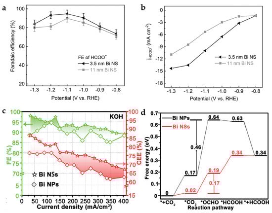
Figure 10.
(a) FEHCOO− of 3.5 nm and 11 nm Bi NSs in CO2-saturated 0.1 M KHCO3. (b) Partial current densities for HCOO− of 3.5 nm and 11 nm Bi NSs [44]. Copyright 2021, Wiley-VCH. (c) FEs and CEEs for HCOOH of Bi NPs and Bi NSs in 1 M KOH. (d) Gibbs free-energy diagrams for CO2 electroreduction to HCOOH on Bi NPs and Bi NSs [45]. Copyright 2020, Wiley-VCH.
Residual Bi-O species are inevitable in the process of electrochemical reduction of CAU-17 to obtain Bi NSs. Compared to the Bi NPs obtained by reduction with the strong reducing agent, e.g., sodium borohydride, the FEs and cathodic energetic efficiency (CEEs) for HCOOH of Bi NSs have shown obviously higher than that of Bi NPs without Bi-O species (Figure 10c). The DFT calculations (Figure 10d) indicate that O atoms at the Bi-O surface of Bi NSs help to reduce the free-energy barrier for forming *OCHO intermediate, resulting in a high FEHCOOH of 97.4% with a current density of 133 mA cm−2 at −0.48 V in the flow cell [45].
The corresponding Bi NPs can be obtained by CAU-7 with BTB as an organic linker. However, compared to Bi-BTC, the larger BTB makes Bi3+ too far apart from each other, leading to unstable dissociative Bi3+ during the electroreduction dissociation process. Finally, only aggregated Bi NPs can be obtained. The NSs structure derived from Bi-BTC is more conducive to adhesion to the surface of the carbon cloth, which promotes the charge transfer between the substrate and the catalyst, and thus exhibits better catalytic activity [46].
Bi-MOF-derived nanosheets (MNS) constructed from BDC can also be obtained by electrochemical reduction [47]. In this process, metal coordination bonds break, and violent structural recombination occurs. The main components of BiMNS are Bi and a small amount of Bi2O3. According to in situ Raman spectra (Figure 11a), the organic-associated peaks disappear with cyclic voltammetry (CV) cycles increasing, demonstrating the disappearance of the organic linkers. Compared with Bi NSs synthesized by conventional wet chemicals, BiMNS shows better stability because the residual ligands on the surface inhibit the dissolution and re-deposition of Bi atoms on the surface, preventing the deactivation of the active sites during long-term electrocatalysis (Figure 11b). This modification strategy can also be applied to synthesize indium-based catalysts, which also show suitable activity and durability.
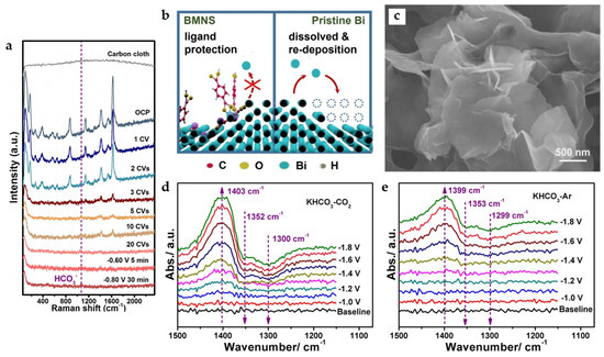
Figure 11.
(a) In situ Raman spectra for showing the transformation from Bi-MOF to BMNS. (b) Proposed mechanism of action for ligands adsorbed on the surface of BiMNS preventing the deactivation of active sites [47]. Copyright 2021, Elsevier. (c) Scanning electron microscopy (SEM) images of Bi-ene. In situ ATR-IR spectra collected under different applied potentials in (d) CO2 and (e) Ar-saturated 0.5 M KHCO3 (all applied potentials are vs. Ag/AgCl in this part) [48]. Copyright 2020, Wiley-VCH.
Metallenes have also received attention due to their high atomic utilization rate. Bi metal–organic layers (MOLs) constructed by 4,5-imidazoledicarboxylic acid (IDC) with unique bilayer structures and a tendency to grow in thin layers can be converted into bismuthene (Bi-ene) with fewer layers by electrochemical reduction. It has an ultra-thin NSs morphology similar to graphene (Figure 11c), and the thickness is only 1.28–1.45 nm, which is the thinnest Bi NSs reported so far. The phase transition involves not only the in situ electrochemical reduction of Bi3+ in Bi-MOLs but also the migration of Bi atoms due to the gradual loss of organic ligands, and the dissociated ligands may serve as soft templates to control the final morphology of Bi-ene. The catalyst reaches FEHCOO− of nearly 100% in the potential range of −0.83 to −1.18 V and maintains this formate selectivity in the flow cell at the current density of 200 mA cm−2. The in situ attenuated total reflection-infrared (ATR-IR) spectra (Figure 11d) suggest that the *OCHO intermediate (the upward peaks at 1403 cm−1) is formed while the absorbed HCO3− groups (the downward peaks at 1352 cm−1 and 1300 cm−1) are consumed. Surprisingly, a similar phenomenon is also observed in in situ ATR-IR spectra under Ar condition (Figure 11e), while formate is detected after electrolysis in Ar-saturated KHCO3. A new mechanism is proposed: when the applied overpotential is low, some easily absorbed HCO3− groups can directly participate in the formation of formate. With the increase in the applied overpotential, formate is produced mainly through the reduction of CO2 in the feed gas and the dissociation of adsorbed HCO3− groups [48].
In addition, it has also been reported that Bi NSs clusters are usually dense, and the atomic utilization rate of Bi NSs is relatively low because only the surface Bi atoms are active. Highly dispersed Bi NPs derived from Bi-BTB MOF have FEHCOO− of 95% at −0.97 V. More importantly, the strategy of using MOF as a pre-catalyst introduces a low load of metal atoms, so the Bi-BTB-derived electrocatalyst achieves a Bi mass activity of 158 A g−1 at −0.97 V, which is superior to most advanced bismuth-based catalysts reported for ECO2RR to formate [49].
4.3. Lead-Based Nanomaterials
Pb-MOF with 5-Chloronicotinic acid (CA) as the organic linker is effectively dispersed on the Pb electrode, and the nanocolumn structure of MOF collapses under the condition of electrochemical reduction. In this process, the inner layer of Pb2+ is reduced to Pb0, while the outer layer of Pb2+ is etched by HCO3− and undergoes the insertion of OH− to form hydrocerussite [Pb3(CO3)2(OH)2] thin film (ER-HC). The formed hydrocerussite film is uniformly and closely attached to Pb and has abundant surface defects, which can improve the activity of ECO2RR and selectivity for HCOOH while effectively inhibiting the HER of Pb, which is originally strong. At −0.88 V, the optimal FEHCOOH is 96.8%, with a current density of 2.0 mA cm−2 [50].
5. MOF-Derived Carbon-Based Nanocomposites
MOF-derived carbon-based nanocomposites can usually be synthesized by carbonizing MOFs rich in organic components. The carbon-based materials linked by covalent bonds provide suitable electrical conductivity, while the high-temperature pyrolysis process provides excellent stability of the catalyst. Organic frameworks act as templates during the carbonization process, effectively dispersing metal NPs and, at the same time, affecting the nano size of active substances in the derivatives. Some of the MOFs stable under the condition of electrochemical reduction can also be carbonized, with great enhancement in conductivity and stability.
5.1. Copper-Based Nanocomposites
Cu-MOF was constructed from BTC derived from Cu2O/Cu carbon-based nanocomposites under pyrolysis. In order to increase the N amount doped in the material, nitrogenous benzimidazoles are also added during the synthesis of the Cu-MOF. The high content of N doping into the Cu2O/Cu lattice changes its electronic structure, reduces the binding energy of *OCHO, and promotes the production of formate. The Cu2O/Cu@NC-800 catalyst synthesized by carbonization at 800 °C has a high Cu content and a suitable distribution of Cu NPs on the porous carbon skeleton, thus resulting in a higher HCOO− selectivity than Cu2O/Cu@NC-700 and Cu2O/Cu@NC-900 (Figure 12a). The Cu2O/Cu@NC-800 reaches the highest FEHCOO− of 70.5% at −0.68 V [29].
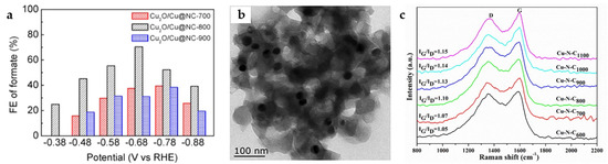
Figure 12.
(a) FEHCOO− for ECO2RR of Cu2O/Cu@NC-700, Cu2O/Cu@NC-800, and Cu2O/Cu@NC-900 [29]. Copyright 2020, ACS. (b) TEM image for Cu–N–C1100. (c) Raman spectra of Cu–N–CT composite catalyst [51]. Copyright 2021, Elsevier.
The calcination of Cu-1,3,5-benzenetris tetrazolate (Cu-BTT) MOF at different temperatures imbeds Cu NPs into a porous carbon matrix with different N and C contents. When the calcination temperature reaches 1100 °C, the pore of the Cu-N-C1100 catalyst is the largest, which is conducive to electron transfer and mass transfer. It has abundant pyrrolic N and Cu-Nx active sites. As the TEM image in Figure 12b shows, Cu NPs (27 ± 2 nm) are effectively dispersed without severe aggregation. The Raman spectra indicate (Figure 12c) that the higher the carbonization temperature, the higher the degree of graphitization, more conducive to electron transfer. Because smaller NPs have stronger CO binding capacity and lower mobility of COad and Had, desorption occurs before further reaction, which inhibits further reactions to form other hydrocarbons, thus effectively improving the selectivity for HCOOH. The Cu-N-C1100 catalyst reaches the maximum FEHCOOH of 38.1% at −0.9 V, while FECO of 40.8% is obtained [51].
5.2. Bismuth-Based Nanocomposites
Calcination in the air is an effective way to introduce oxides. Bi-BTC MOF is carbonized at 800 °C to obtain Bi@C and further oxidized in air (200 °C) to obtain Bi2O3@C-800 (Figure 13a). The presence of Bi2O3 facilitates the improvement of reaction kinetics and product selectivity, while the carbon matrix synergistically helps in further increasing the activity and current density, showing superior catalytic performance compared to Bi@C. Bi2O3@C-800 reaches FEHCOO− of 92% with a current density of 7.5 mA cm−2 at −0.9 V and can maintain more than FEHCOO− of 93% for 10 h with a current density of 200 mA cm−2 in the flow cell [31].
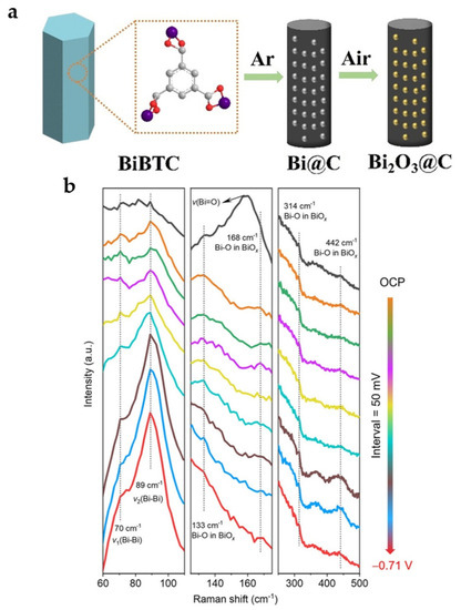
Figure 13.
(a) Preparation of Bi@C and Bi2O3@C catalysts [31]. Copyright 2020, Wiley-VCH. (b) In situ Raman spectra of the (surface-oxygen-rich) SOR Bi@C NPs catalyst as a function of the applied potential in 1.0 M KOH electrolyte at various potentials [52]. Copyright 2022, ACS.
To obtain a more stable Bi-O structure, the most stable Bi-MOF SU-101 under electrochemical reduction is carbonized to obtain surface-oxygen-rich carbon-nanorod-supported Bi NPs (SOR Bi@C NPs) with uniform distribution of active sites, retaining the original nanorod morphology of SU-101 with a large number of Bi-O species present on the surface. The maximum FEHCOO− of 95% and the corresponding partial current density of 10.5 mA cm−2 are obtained at −0.99 V. As shown in in situ Raman spectra (Figure 13b), three Raman peaks located at 133, 314, and 442 cm−1 remained at different reduction potentials, demonstrating that Bi-O/Bi species are structurally stable during ECO2RR [52].
5.3. Indium-Based Nanocomposites
Interestingly, calcination under N2 can produce more oxygen vacancies compared to air. The corn-like In2O3−X@C nanocomposite is obtained by carbonization of MIL-68 (In MOF) with BDC as the organic linker. The combination of abundant oxygen vacancies and amorphous carbon rods contributes to the increase in electrical conductivity and catalytic activity. According to DFT calculations (Figure 14a,b), In2O3−X exhibits a tendency to spontaneously form HCOO* (*OCHO) intermediates while effectively raising the energy barrier for the formation of *COOH intermediates, thus greatly improving the selectivity for HCOOH products. In addition, the valence state changes during the reaction are probed by operando X-ray absorption spectroscopy (XAS). As shown in Figure 14c, at −0.445 V, the In valence state is below +2 with almost no HCOOH produced. When the potential is increased to −1.045 V, the FEHCOOH increases to more than 85%, and the In valence state is about +3. When the potential is further increased to −1.445 V, the FEHCOOH decreases to 51%, with the valence state of In decreasing to ~+2.5. This suggests a possible reaction mechanism (Figure 14d): the catalyst may shift to In0 during the initial reduction phase, transform back to In3+ after electron transfer to CO2, and maintain the valence as the active sites [53].
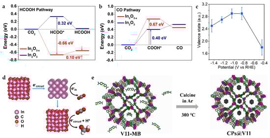
Figure 14.
(a) Free-energy diagrams for CO2 electroreduction to HCOOH and (b) CO on In2O3 and In2O3−x. (c) Changes in In valence state in MIL-68-N2 under different applied potentials, which are examined by using the K-edge energy shift with respect to the commercial In2O3 sample. (d) The proposed reaction mechanism based on the operando measurements [53]. Copyright 2022, Springer Nature. (e) Illustration of the preparation process of CPs@V11 [54]. Copyright 2021, Wiley-VCH.
The In MOF {(Me2NH2)[In(BCP)]·2DMF}n (V11) constructed by 5-(2,6-bis(4-carboxyphenyl) pyridin-4-yl) isophthalic acid (BCP), exhibits certain catalytic potential as well as suitable thermal stability, but the poor conductivity limits its catalytic efficiency, which can be effectively improved by the introduction of carbon materials. Methylene blue (MB) meets the integrating conditions considering the molecular structure size and carbonization temperature. MB transforms into carbon nanoparticles at temperatures above 250 °C, while V11 can maintain structural stability at 380 °C, and thus, V11 framework-loaded carbon nanoparticles (CPs) can be formed in this temperature range (Figure 14e). MB-derived CPs are used as promoters to improve the conductivity of the material and expose more active sites, which facilitates the charge and mass transfer during the reaction. Importantly, this strategy can also be applied to other classical MOFs, demonstrating the generality of this strategy [54].
Single-atom catalysts with almost 100% atomic utilization rate have been shown to be ideal catalysts for ECO2RR. Once dispersed into a single atomic form, the electronic structure of the active component is significantly altered, favoring the stabilization of reaction intermediates (e.g., CO2−) and limiting the configurations of the intermediates [62].
The pyrolysis process of ZIF-8 (Zn MOF) with In doping leads to the formation of a single-atom catalyst In-SAs/NC. HAADF-STEM image, as well as Fourier, transform curve of extended X-ray absorption fine structure (EXAFS) spectra (Figure 15a,b), demonstrate the apparent In-N4 single-atom structure. The catalyst demonstrates a very high TOF of 12,500 h−1 at −0.95 V and a FEHCOO− of 96% at −0.65 V with a current density of 8.87 mA cm−2. According to DFT calculations (Figure 15c), the In-N4 structure effectively lowers the formation energy barrier of *OCHO intermediate. Notably, the single-atom synthesis strategy can also be applied to Sn and Sb, and the obtained single-atom catalyst also exhibits high selectivity for formate products [55]. The similar reported single-atom catalyst In-N-C also exhibits high HCOOH selectivity and atomic utilization rate, with TOF reaching 26,671 h−1 at −0.99 V [56].
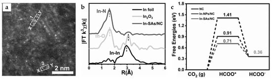
Figure 15.
(a) High-angle annular dark-field scanning transmission electron microscope (HAADF-STEM) image of In-SAs/NC. (b) In K-edge FT-EXAFS spectrum of In-SAs/NC. (c) The calculated potential free-energy diagrams for CO2 electroreduction to formate [55]. Copyright 2022, Wiley-VCH.
6. Bimetallic MOF-Derived Nanocomposites
Compared with monometallic sites, bimetallic sites can change the atomic arrangement and modulate the electronic structure through the interaction of adjacent metal atoms [59]. Bimetallic electrocatalysts with rational design can effectively reduce the energy barrier between CO2 and reduction intermediates through synergistic effects and inhibits the competitive HER, resulting in low overpotential and enhanced selectivity for ECO2RR [57]. Carbonization and electrochemical reduction of bimetallic MOFs are both effective ways to construct MOF-derived bimetallic nanocomposite catalysts.
6.1. Copper and Bismuth-Based Bimetallic Nanocomposites
The carbon-based nanomaterial Cux-Bi/Bi2O3@C with bimetallic composition is obtained by a calcination process from Cu, Bi bi-MOF (x represents the mass ratio of Cu(NO3)2·3H2O, and Bi(NO3)2·5H2O in the synthesis). Compared to Bi/Bi2O3@C without Cu, the HCOOH selectivity is significantly enhanced, reaching a high FE of 93% at −0.94 V (Figure 16a). This can be attributed to the synergistic effect between Cu and Bi, where the introduction of Cu can substantially inhibit HER and enhance the adsorption capacity of CO2− intermediates, effectively reducing the CO2 activation energy barrier. With the increase in Cu content, the content of Bi3+ decreases while that of Bi0 increases, and appropriate Cu doping also favors the increase in oxygen defects. In addition, a suitable Bi0/Bi3+ ratio and the synergistic coordination of Bi0 and Bi3+ are considered to contribute to the enhancement of ECO2RR. Cu1-Bi/Bi2O3@C exhibits better catalytic activity and HCOOH selectivity compared to Cu0.5-Bi/Bi2O3@C (Figure 16a,b) [22].
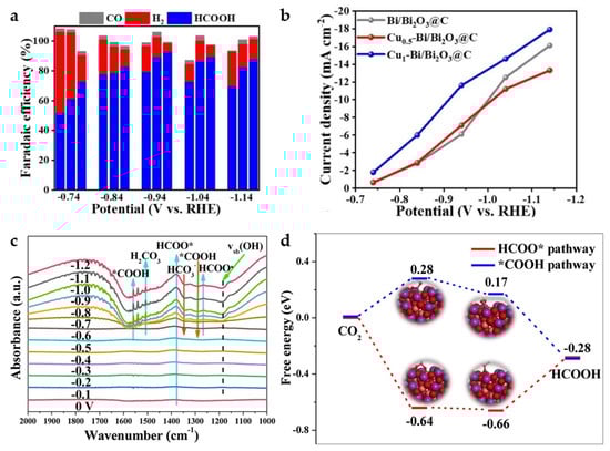
Figure 16.
(a) FE of H2, CO, HCOOH for Cux-Bi/Bi2O3@C (x = 0, 0.5, 1). (b) Partial current density of HCOOH of different catalysts [22]. Copyright 2022, Wiley-VCH. (c) The in situ FT-IR spectra on CuBi75 catalyst at different applied potentials from 0 V to −1.2 V. (d) The free-energy diagrams of different pathways for CO2 electroreduction to HCOOH on CuBi75 (211) plane [57]. Copyright 2021, Elsevier.
A similar Bi and Cu bimetallic MOF-derived catalyst was reported in the same year. CuBi75 (75 represents that the molar mass ratio of Cu(NO3)2 and Bi(NO3)3 added is 75:25 in the synthesis) is found to produce a unique Bi2CuO4 structure at the interface between Cu and Bi, leading to a greatly enhanced activity and formate selectivity of the bimetallic Cu Bi catalyst. A significant increase in the peak intensity of HCOO* at ~1379 cm−1 is found by in situ FT-IR (Figure 16c) from 0 V to −1.2 V, indicating that the accumulation of HCOO* intermediates on CuBi75 exceeds the consumption, making the reaction pathway more inclined to HCOO− generation. The DFT calculations (Figure 16d) also suggest that Bi2CuO4 favors the promotion of the HCOO* (*OCHO) pathway while inhibiting the *COOH reaction pathway to achieve high formate selectivity. FEHCOO− of the catalyst achieves more than 93.7% over a wide potential range of 900 mV (−0.57 V to −1.47 V), with a maximum FEHCOO− of 100% at −0.77 V [57].
6.2. Bismuth and Indium-Based Bimetallic Nanocomposites
Bi has relatively weak binding energy to *OCHO, which makes it difficult to promote HCOOH production in ECO2RR. The electronic structure can be regulated through interaction with In. In-Bi-MOF is synthesized by a solvothermal method and ion-exchange process. The subsequent Bi-In alloy NPs are obtained by electrochemical reduction. The electronic interaction between In and Bi in Bi-In alloy NPs is demonstrated by XPS spectra (Figure 17a,b). The XPS peaks of Bi 4f shift toward a lower binding energy compared to Bi NPs, while the XPS peaks of In 3d shift toward a higher binding energy compared to In NPs, indicating electron transfer from In to Bi. Bi-In alloy NPs reach a maximum FEHCOOH of 97.8% in H-cell at −0.92 V and a FEHCOOH of 92.5% with a high current density of 300 mA cm−2 in the flow cell. In addition, the Bi-In alloy NPs achieve long-term electrolysis for more than 25 h in the MEA system at a current density of 120 mA cm−2, maintaining FEHCOOH of above 80%. The results of DFT calculations (Figure 17c,d) demonstrate that the bimetallic sites provide the best *OCHO binding energy and promote the generation of HCOOH [58].
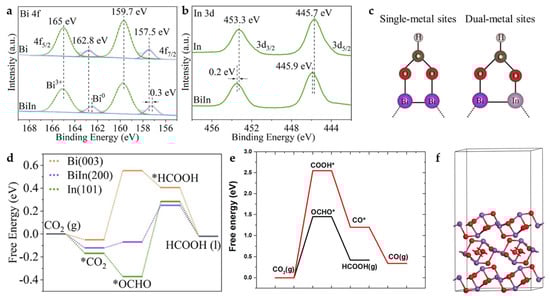
Figure 17.
(a) Bi 4f XPS spectra of Bi-In alloy NPs and Bi NPs. (b) In 3d XPS spectra of Bi-In alloy NPs, and In NPs. (c) *OCHO adsorption in single-metal (left) and dual-metal (right) catalytic systems through side-on configurations. (d) Calculated free-energy diagrams for CO2 electroreduction to HCOOH on Bi (003), Bi-In (200), and In (101) [58]. Copyright 2022, Elsevier. (e) Free-energy diagrams for CO2 electroreduction to HCOOH and CO on Bi2O3 (010). (f) Optimized structures of Bi2O3 (010) [59]. Copyright 2021, Elsevier.
In addition, BiIn5-500@C, a carbon-based nanocomposite catalyst containing In2O3 and Bi2O3, is synthesized by carbonizing In-Bi-MOF [59]. A significant synergistic effect is observed at 5% In doping, and almost no In aggregation occurs. The DFT calculations (Figure 17e,f) show that the addition of In to Bi significantly reduces the free energy of the formation of *OCHO intermediates. The catalyst achieves a FEHCOOH of 97.5% at −0.86 V and a current density of 13.5 mA cm−2, showing higher activity and HCOOH selectivity compared to Bi-500@C.
6.3. Palladium and Gold-Based Bimetallic Nanocomposites
Pd is a catalyst capable of ECO2RR to HCOOH at a very low overpotential [63]. However, palladium-based electrocatalysts present significant challenges in terms of long-term stability, as trace amounts of CO are inevitably generated during ECO2RR, which can strongly adsorb on the Pd surface and leads to poisoning. Reduction in Pd precursors in the limited space of MOFs generates significant local tensile strain in the Pd NPs, which remains when a certain amount of Au is added to form M-AuPd. As the Cs-TEM image shows (Figure 18a), the pink dots indicate the dislocations and lattice distortions on the surface of the catalyst. Interestingly, the generation of tensile strain on the Pd surface typically enhances the adsorption energy of ECO2RR intermediates, including *COOH and *OOCH (*OCHO), while the dispersal of a single Au atom on the tensile-strained Pd surface selectively destabilizes *CO without affecting the other adsorbates. At a very positive potential, −0.25 V, FEHCOOH of above 99% and a current density of ~7 mA cm−2 are obtained, far exceeding commercial Pd/C and M-Pd without Au in catalytic activity and selectivity for formate (Figure 18b,c) [18].
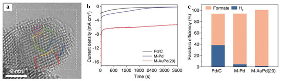
Figure 18.
(a) Cs-corrected TEM (Cs-TEM) image of M-AuPd(20). The dislocations are indicated with pink dots. (b) Chronoamperometric curves, (c) FEHCOOH of Pd/C, M-Pd, and M-AuPd(20) at −0.25 V for 1 h [18]. Copyright 2021, ACS.
7. Summary and Outlook
In conclusion, we summarize the MOFs and MOF-derived catalysts applied in ECO2RR for HCOOH. MOFs are widely used for catalysis due to their high specific surface area and porous structure. Their high CO2 adsorption capacity, uniformly distributed active sites, and restricted reaction space give them the potential for ECO2RR. However, the application of pristine MOFs in electrocatalysis must face the problems of poor conductivity and instability under electroreduction conditions, and some MOFs even undergo SALE/electrolyte-mediated dissociation processes during immersion in HCO3− electrolyte. Interestingly, the latter problem becomes a solution to the former one. A series of MOFs undergo structural decomposition under electrochemical reduction conditions to form derived metal nanomaterials, accompanied by an increase in electrical conductivity and stability. Compared to conventional reduction methods, the electroreduction process is gentler and retains M-O species, and the M-O species become an important factor in optimizing catalytic performance. Another important derivation method is calcination/carbonization to obtain carbon-based metal nanocomposites. MOF structures as the precursor can effectively decrease the degree of metal aggregation and improve the atomic utilization rate and can even be a method for synthesizing single-atom catalysts. At the same time, MOF structures often act as templates to influence the morphology of carbonization-derived catalysts. Depending on different reaction conditions and structural units, including metal ions and organic linkers, it is therefore easy to tune and optimize the performance of MOF-derived catalysts, which have rich variability and application range.
On the other hand, the most widely reported bismuth-based MOF catalysts dominate in ECO2RR for HCOOH, with FEHCOOH generally exceeding 90%, and the advantages of low toxicity make Bi the most promising catalysts for practical applications at this stage. In and tin-based MOFs also show suitable HCOOH selectivity. Palladium-based MOFs exhibit impressive low overpotential properties but may be difficult for applications due to their noble metal status and susceptibility to poisoning. However, Cu is the only catalyst capable of CO2 reduction to highly reduced products such as CH4, CH3COOH, C2H4, and further exploration in this field should be directed toward C-C coupling and C2+ products. In addition, two-component or multi-component metal MOFs are more complex. How to determine the active sites and the synergistic effect between multiple components still need to be further explored.
The design of efficient catalysts is challenging, and although so much work has been performed to show that MOFs undergo recombination by carbonization or electrochemical reduction, how to rationally control the recombination process to form a more reactive structure remains to be further investigated. A sufficient understanding of the catalytic system is required. Therefore, the correlation between catalytic activity and the physical parameters of MOFs, such as the ligand structure, composition, specific surface area, pore structure, and morphology, needs to be further constructed. Future directions will include the study of the role of substituents on organic linkers to develop MOFs with more efficient CO2 capture and high ECO2RR performance [41]. In situ studies are also necessary for tracing the evolution of catalysts during the electrolysis process and further understanding the mechanism of ECO2RR catalyzed by metal active sites in MOFs and their derivatives, where Operando Raman, IR, and XAFS are powerful and widely used tools to obtain information on catalyst structure, adsorbates on the catalyst surface such as CO2 reduction intermediates, metal valence, and coordination number [53].
Author Contributions
Investigation, data curation, writing—original draft preparation, W.-J.X.; writing—writing—original draft preparation, and review, O.M.M. and A.O.T.—review; and L.-N.H.—review and editing, supervision, project administration. All authors have read and agreed to the published version of the manuscript.
Funding
This work was financially supported by the National Natural Science Foundation of China (22171149, 21975135), the National Key Research and Development Program of China (2022YFB4101800), the Natural Science Foundation of Tianjin Municipal Science and Technology Commission (21JCZDJC00100), and the Fundamental Research Funds for the Central Universities, Nankai University, and Nankai Cangzhou Bohai New Area Green Chemical Research Co., Ltd. (grant no. 20220130).
Data Availability Statement
Not applicable.
Conflicts of Interest
The authors declare no conflict of interest. The funders had no role in the design of the study; in the collection, analyses, or interpretation of data; in the writing of the manuscript; or in the decision to publish the results.
References
- Abdelkader-Fernández, V.K.; Fernandes, D.M.; Freire, C. Carbon-based electrocatalysts for CO2 electroreduction produced via MOF, biomass, and other precursors carbonization: A review. J. CO2 Util. 2020, 42, 101350. [Google Scholar] [CrossRef]
- Yang, Z.W.; Chen, J.M.; Qiu, L.Q.; Xie, W.J.; He, L.N. Molecular Engineering of Metal Complexes for Electrocatalytic Carbon Dioxide Reduction: From Adjustment of Intrinsic Activity to Molecular Immobilization. Angew. Chem. Int. Ed. 2022, 61, e202205301. [Google Scholar]
- Mahmood, A.; Guo, W.; Tabassum, H.; Zou, R. Metal-Organic Framework-Based Nanomaterials for Electrocatalysis. Adv. Energy Mater. 2016, 6, 1600423. [Google Scholar] [CrossRef]
- Zhang, W.; Hu, Y.; Ma, L.; Zhu, G.; Wang, Y.; Xue, X.; Chen, R.; Yang, S.; Jin, Z. Progress and Perspective of Electrocatalytic CO2 Reduction for Renewable Carbonaceous Fuels and Chemicals. Adv. Sci. 2018, 5, 1700275. [Google Scholar] [CrossRef]
- Raciti, D.; Wang, C. Recent Advances in CO2 Reduction Electrocatalysis on Copper. ACS Energy Lett. 2018, 3, 1545–1556. [Google Scholar] [CrossRef]
- Wang, Y.; Su, H.; He, Y.; Li, L.; Zhu, S.; Shen, H.; Xie, P.; Fu, X.; Zhou, G.; Feng, C.; et al. Advanced Electrocatalysts with Single-Metal-Atom Active Sites. Chem. Rev. 2020, 120, 12217–12314. [Google Scholar] [CrossRef]
- Masood ul Hasan, I.; Peng, L.; Mao, J.; He, R.; Wang, Y.; Fu, J.; Xu, N.; Qiao, J. Carbon-based metal-free catalysts for electrochemical CO2 reduction: Activity, selectivity, and stability. Carbon Energy 2020, 3, 24–49. [Google Scholar] [CrossRef]
- Fellay, C.; Yan, N.; Dyson, P.J.; Laurenczy, G. Selective formic acid decomposition for high-pressure hydrogen generation: A mechanistic study. Chem. Eur. J. 2009, 15, 3752–3760. [Google Scholar] [CrossRef]
- Liu, M.; Xu, Y.; Meng, Y.; Wang, L.; Wang, H.; Huang, Y.; Onishi, N.; Wang, L.; Fan, Z.; Himeda, Y. Heterogeneous Catalysis for Carbon Dioxide Mediated Hydrogen Storage Technology Based on Formic Acid. Adv. Energy Mater. 2022, 12, 2200817. [Google Scholar] [CrossRef]
- Xia, S.-M.; Yang, Z.-W.; Yao, X.-Y.; Chen, K.-H.; Qiu, L.-Q.; He, L.-N. The synergistic copper/ppm Pd-catalyzed hydrocarboxylation of alkynes with formic acid as a CO surrogate as well as a hydrogen source: An alternative indirect utilization of CO2. Green Chem. 2021, 23, 8089–8095. [Google Scholar] [CrossRef]
- Xia, S.-M.; Yang, Z.-W.; Chen, K.-H.; Wang, N.; He, L.-N. Efficient hydrocarboxylation of alkynes based on carbodiimide-regulated in situ CO generation from HCOOH: An alternative indirect utilization of CO2. Chin. J. Catal. 2022, 43, 1642–1651. [Google Scholar] [CrossRef]
- Evans, H.A.; Mullangi, D.; Deng, Z.; Wang, Y.; Peh, S.B.; Wei, F.; Wang, J.; Brown, C.M.; Zhao, D.; Canepa, P.; et al. Aluminum formate, Al(HCOO)3: An earth-abundant, scalable, and highly selective material for CO2 capture. Sci. Adv. 2022, 8, 1473. [Google Scholar] [CrossRef]
- Mullangi, D.; Evans, H.A.; Yildirim, T.; Wang, Y.; Deng, Z.; Zhang, Z.; Mai, T.T.; Wei, F.; Wang, J.; Hight Walker, A.R.; et al. Noncryogenic Air Separation Using Aluminum Formate Al(HCOO)3 (ALF). J. Am. Chem. Soc. 2023, 145, 9850–9856. [Google Scholar] [CrossRef] [PubMed]
- Zhang, Z.; Deng, Z.; Evans, H.A.; Mullangi, D.; Kang, C.; Peh, S.B.; Wang, Y.; Brown, C.M.; Wang, J.; Canepa, P.; et al. Exclusive Recognition of CO2 from Hydrocarbons by Aluminum Formate with Hydrogen-Confined Pore Cavities. J. Am. Chem. Soc. 2023, 145, 11643–11649. [Google Scholar] [CrossRef] [PubMed]
- Duarah, P.; Haldar, D.; Yadav, V.S.K.; Purkait, M.K. Progress in the electrochemical reduction of CO2 to formic acid: A review on current trends and future prospects. J. Environ. Chem. Eng. 2021, 9, 106394. [Google Scholar] [CrossRef]
- Li, F.; Gu, G.H.; Choi, C.; Kolla, P.; Hong, S.; Wu, T.-S.; Soo, Y.-L.; Masa, J.; Mukerjee, S.; Jung, Y.; et al. Highly stable two-dimensional bismuth metal-organic frameworks for efficient electrochemical reduction of CO2. Appl. Catal. B 2020, 277, 119241. [Google Scholar] [CrossRef]
- Zhang, R.-Z.; Wu, B.-Y.; Li, Q.; Lu, L.-L.; Shi, W.; Cheng, P. Design strategies and mechanism studies of CO2 electroreduction catalysts based on coordination chemistry. Coord. Chem. Rev. 2020, 422, 213436. [Google Scholar] [CrossRef]
- Bok, J.; Lee, S.Y.; Lee, B.H.; Kim, C.; Nguyen, D.L.T.; Kim, J.W.; Jung, E.; Lee, C.W.; Jung, Y.; Lee, H.S.; et al. Designing Atomically Dispersed Au on Tensile-Strained Pd for Efficient CO2 Electroreduction to Formate. J. Am. Chem. Soc. 2021, 143, 5386–5395. [Google Scholar] [CrossRef]
- Kortlever, R.; Shen, J.; Schouten, K.J.; Calle-Vallejo, F.; Koper, M.T. Catalysts and Reaction Pathways for the Electrochemical Reduction of Carbon Dioxide. J. Phys. Chem. Lett. 2015, 6, 4073–4082. [Google Scholar] [CrossRef]
- Li, X.; Yang, X.; Xue, H.; Pang, H.; Xu, Q. Metal-organic frameworks as a platform for clean energy applications. EnergyChem 2020, 2, 100027. [Google Scholar] [CrossRef]
- Chughtai, A.H.; Ahmad, N.; Younus, H.A.; Laypkov, A.; Verpoort, F. Metal-organic frameworks: Versatile heterogeneous catalysts for efficient catalytic organic transformations. Chem. Soc. Rev. 2015, 44, 6804–6849. [Google Scholar] [CrossRef] [PubMed]
- Xue, Y.; Li, C.; Zhou, X.; Kuang, Z.; Zhao, W.; Zhang, Q.; Chen, H. MOF-Derived Cu/Bi Bi-metallic Catalyst to Enhance Selectivity Toward Formate for CO2 Electroreduction. ChemElectroChem 2022, 9, e202101648. [Google Scholar] [CrossRef]
- Geng, W.; Chen, W.; Li, G.; Dong, X.; Song, Y.; Wei, W.; Sun, Y. Induced CO2 Electroreduction to Formic Acid on Metal-Organic Frameworks via Node Doping. ChemSusChem 2020, 13, 4035–4040. [Google Scholar] [CrossRef] [PubMed]
- Hinogami, R.; Yotsuhashi, S.; Deguchi, M.; Zenitani, Y.; Hashiba, H.; Yamada, Y. Electrochemical Reduction of Carbon Dioxide Using a Copper Rubeanate Metal Organic Framework. ECS Electrochem. Lett. 2012, 1, H17–H19. [Google Scholar] [CrossRef]
- Wang, R.; Liu, J.; Huang, Q.; Dong, L.Z.; Li, S.L.; Lan, Y.Q. Partial Coordination-Perturbed Bi-Copper Sites for Selective Electroreduction of CO2 to Hydrocarbons. Angew. Chem. Int. Ed. 2021, 60, 19829–19835. [Google Scholar] [CrossRef]
- Zhuo, L.L.; Chen, P.; Zheng, K.; Zhang, X.W.; Wu, J.X.; Lin, D.Y.; Liu, S.Y.; Wang, Z.S.; Liu, J.Y.; Zhou, D.D.; et al. Flexible Cuprous Triazolate Frameworks as Highly Stable and Efficient Electrocatalysts for CO2 Reduction with Tunable C2H4/CH4 Selectivity. Angew. Chem. Int. Ed. 2022, 61, e202204967. [Google Scholar] [CrossRef]
- Wu, J.X.; Hou, S.Z.; Zhang, X.D.; Xu, M.; Yang, H.F.; Cao, P.S.; Gu, Z.Y. Cathodized copper porphyrin metal-organic framework nanosheets for selective formate and acetate production from CO2 electroreduction. Chem. Sci. 2019, 10, 2199–2205. [Google Scholar] [CrossRef]
- Zheng, W.; Lee, L.Y.S. Metal-Organic Frameworks for Electrocatalysis: Catalyst or Precatalyst? ACS Energy Lett. 2021, 6, 2838–2843. [Google Scholar] [CrossRef]
- Li, D.; Liu, T.; Yan, Z.; Zhen, L.; Liu, J.; Wu, J.; Feng, Y. MOF-Derived Cu2O/Cu Nanospheres Anchored in Nitrogen-Doped Hollow Porous Carbon Framework for Increasing the Selectivity and Activity of Electrochemical CO2-to-Formate Conversion. ACS Appl. Mater. Interfaces 2020, 12, 7030–7037. [Google Scholar] [CrossRef]
- Guan, B.Y.; Yu, X.Y.; Wu, H.B.; Lou, X.W.D. Complex Nanostructures from Materials based on Metal-Organic Frameworks for Electrochemical Energy Storage and Conversion. Adv. Mater. 2017, 29, 1703614. [Google Scholar] [CrossRef]
- Deng, P.; Yang, F.; Wang, Z.; Chen, S.; Zhou, Y.; Zaman, S.; Xia, B.Y. Metal-Organic Framework-Derived Carbon Nanorods Encapsulating Bismuth Oxides for Rapid and Selective CO2 Electroreduction to Formate. Angew. Chem. Int. Ed. 2020, 59, 10807–10813. [Google Scholar] [CrossRef]
- Wang, J.; Zhang, Y.; Ma, Y.; Yin, J.; Wang, Y.; Fan, Z. Electrocatalytic Reduction of Carbon Dioxide to High-Value Multicarbon Products with Metal–Organic Frameworks and Their Derived Materials. ACS Mater. Lett. 2022, 4, 2058–2079. [Google Scholar] [CrossRef]
- Hwang, S.M.; Choi, S.Y.; Youn, M.H.; Lee, W.; Park, K.T.; Gothandapani, K.; Grace, A.N.; Jeong, S.K. Investigation on Electroreduction of CO2 to Formic Acid Using Cu3(BTC)2 Metal-Organic Framework (Cu-MOF) and Graphene Oxide. ACS Omega 2020, 5, 23919–23930. [Google Scholar] [CrossRef] [PubMed]
- Liu, M.J.; Cao, S.M.; Feng, B.Q.; Dong, B.X.; Ding, Y.X.; Zheng, Q.H.; Teng, Y.L.; Li, Z.W.; Liu, W.L.; Feng, L.G. Revealing the structure-activity relationship of two Cu-porphyrin-based metal-organic frameworks for the electrochemical CO2-to-HCOOH transformation. Dalton Trans. 2020, 49, 14995–15001. [Google Scholar] [CrossRef]
- Yuan, W.-W.; Wu, J.-X.; Zhang, X.-D.; Hou, S.-Z.; Xu, M.; Gu, Z.-Y. In situ transformation of bismuth metal–organic frameworks for efficient selective electroreduction of CO2 to formate. J. Mater. Chem. A 2020, 8, 24486–24492. [Google Scholar] [CrossRef]
- Liu, L.; Yao, K.; Fu, J.; Huang, Y.; Li, N.; Liang, H. Bismuth metal-organic framework for electroreduction of carbon dioxide. Colloids Surf. A 2022, 633, 127840. [Google Scholar] [CrossRef]
- Yang, Z.W.; Chen, J.M.; Liang, Z.L.; Xie, W.J.; Zhao, B.; He, L.N. Anodic Product-Derived Bi-MOF as Pre-catalyst for Cathodic CO2 Reduction: A Novel Strategy for Paired Electrolysis. ChemCatChem 2022, 15, e202201321. [Google Scholar]
- Frank, S.; Svensson Grape, E.; Bøjesen, E.D.; Larsen, R.; Lamagni, P.; Catalano, J.; Inge, A.K.; Lock, N. Exploring the influence of atomic level structure, porosity, and stability of bismuth(III) coordination polymers on electrocatalytic CO2 reduction. J. Mater. Chem. A 2021, 9, 26298–26310. [Google Scholar] [CrossRef]
- Hou, S.Z.; Zhang, X.D.; Yuan, W.W.; Li, Y.X.; Gu, Z.Y. Indium-Based Metal-Organic Framework for High-Performance Electroreduction of CO2 to Formate. Inorg. Chem. 2020, 59, 11298–11304. [Google Scholar] [CrossRef]
- Deng, Y.; Wang, S.; Huang, Y.; Li, X. Structural reconstruction of Sn-based metal–organic frameworks for efficient electrochemical CO2 reduction to formate. Chin. J. Chem. Eng. 2022, 43, 353–359. [Google Scholar] [CrossRef]
- Lee, M.; De Riccardis, A.; Kazantsev, R.V.; Cooper, J.K.; Buckley, A.K.; Burroughs, P.W.W.; Larson, D.M.; Mele, G.; Toma, F.M. Aluminum Metal-Organic Framework Triggers Carbon Dioxide Reduction Activity. ACS Appl. Energy Mater. 2020, 3, 1286–1291. [Google Scholar] [CrossRef]
- Kung, C.-W.; Audu, C.O.; Peters, A.W.; Noh, H.; Farha, O.K.; Hupp, J.T. Copper Nanoparticles Installed in Metal-Organic Framework Thin Films are Electrocatalytically Competent for CO2 Reduction. ACS Energy Lett. 2017, 2, 2394–2401. [Google Scholar] [CrossRef]
- Wang, D.; Xu, J.; Zhu, Y.; Wen, L.; Ye, J.; Shen, Y.; Zeng, T.; Lu, X.; Ma, J.; Wang, L.; et al. HKUST-1-derived highly ordered Cu nanosheets with enriched edge sites, stepped (211) surfaces and (200) facets for effective electrochemical CO2 reduction. Chemosphere 2021, 278, 130408. [Google Scholar] [CrossRef] [PubMed]
- Yao, D.; Tang, C.; Vasileff, A.; Zhi, X.; Jiao, Y.; Qiao, S.Z. The Controllable Reconstruction of Bi-MOFs for Electrochemical CO2 Reduction through Electrolyte and Potential Mediation. Angew. Chem. Int. Ed. 2021, 60, 18178–18184. [Google Scholar] [CrossRef] [PubMed]
- Yang, J.; Wang, X.; Qu, Y.; Wang, X.; Huo, H.; Fan, Q.; Wang, J.; Yang, L.M.; Wu, Y. Bi-Based Metal-Organic Framework Derived Leafy Bismuth Nanosheets for Carbon Dioxide Electroreduction. Adv. Energy Mater. 2020, 10, 2001709. [Google Scholar] [CrossRef]
- Zhang, B.; Cao, S.; Wu, Y.; Zhai, P.; Li, Z.; Zhang, Y.; Fan, Z.; Wang, C.; Zhang, X.; Hou, J.; et al. Metal-Organic-Framework-Derived Bismuth Nanosheets for Electrochemical and Solar-Driven Electrochemical CO2 Reduction to Formate. ChemElectroChem 2021, 8, 880–886. [Google Scholar] [CrossRef]
- Li, N.; Yan, P.; Tang, Y.; Wang, J.; Yu, X.-Y.; Wu, H.B. In-situ formation of ligand-stabilized bismuth nanosheets for efficient CO2 conversion. Appl. Catal. B 2021, 297, 120481. [Google Scholar] [CrossRef]
- Cao, C.; Ma, D.D.; Gu, J.F.; Xie, X.; Zeng, G.; Li, X.; Han, S.G.; Zhu, Q.L.; Wu, X.T.; Xu, Q. Metal-Organic Layers Leading to Atomically Thin Bismuthene for Efficient Carbon Dioxide Electroreduction to Liquid Fuel. Angew. Chem. Int. Ed. 2020, 59, 15014–15020. [Google Scholar] [CrossRef] [PubMed]
- Lamagni, P.; Miola, M.; Catalano, J.; Hvid, M.S.; Mamakhel, M.A.H.; Christensen, M.; Madsen, M.R.; Jeppesen, H.S.; Hu, X.M.; Daasbjerg, K.; et al. Restructuring Metal–Organic Frameworks to Nanoscale Bismuth Electrocatalysts for Highly Active and Selective CO2 Reduction to Formate. Adv. Funct. Mater. 2020, 30, 1910408. [Google Scholar] [CrossRef]
- Wang, D.; Dong, S.; Wen, L.; Yu, W.; He, Z.; Guo, Q.; Lu, X.; Wang, L.; Song, S.; Ma, J. Highly selective electrocatalytic reduction of CO2 to HCOOH over an in situ derived hydrocerussite thin film on a Pb substrate. Chemosphere 2022, 291, 132889. [Google Scholar] [CrossRef]
- Cao, S.-M.; Chen, H.-B.; Dong, B.-X.; Zheng, Q.-H.; Ding, Y.-X.; Liu, M.-J.; Qian, S.-L.; Teng, Y.-L.; Li, Z.-W.; Liu, W.-L. Nitrogen-rich metal-organic framework mediated Cu–N–C composite catalysts for the electrochemical reduction of CO2. J. Energy Chem. 2021, 54, 555–563. [Google Scholar] [CrossRef]
- Liu, S.; Fan, Y.; Wang, Y.; Jin, S.; Hou, M.; Zeng, W.; Li, K.; Jiang, T.; Qin, L.; Yan, Z.; et al. Surface-Oxygen-Rich Bi@C Nanoparticles for High-Efficiency Electroreduction of CO2 to Formate. Nano Lett. 2022, 22, 9107–9114. [Google Scholar] [CrossRef] [PubMed]
- Qiu, C.; Qian, K.; Yu, J.; Sun, M.; Cao, S.; Gao, J.; Yu, R.; Fang, L.; Yao, Y.; Lu, X.; et al. MOF-Transformed In2O3−x@C Nanocorn Electrocatalyst for Efficient CO2 Reduction to HCOOH. Nano Micro Lett. 2022, 14, 167. [Google Scholar] [CrossRef] [PubMed]
- Zhu, Z.H.; Zhao, B.H.; Hou, S.L.; Jiang, X.L.; Liang, Z.L.; Zhang, B.; Zhao, B. A Facile Strategy for Constructing a Carbon-Particle-Modified Metal-Organic Framework for Enhancing the Efficiency of CO2 Electroreduction into Formate. Angew. Chem. Int. Ed. 2021, 60, 23394–23402. [Google Scholar] [CrossRef]
- Shang, H.; Wang, T.; Pei, J.; Jiang, Z.; Zhou, D.; Wang, Y.; Li, H.; Dong, J.; Zhuang, Z.; Chen, W.; et al. Design of a Single-Atom Indiumδ+-N4 Interface for Efficient Electroreduction of CO2 to Formate. Angew. Chem. Int. Ed. 2020, 59, 22465–22469. [Google Scholar] [CrossRef]
- Lu, P.; Tan, X.; Zhao, H.; Xiang, Q.; Liu, K.; Zhao, X.; Yin, X.; Li, X.; Hai, X.; Xi, S.; et al. Atomically Dispersed Indium Sites for Selective CO2 Electroreduction to Formic Acid. ACS Nano 2021, 15, 5671–5678. [Google Scholar] [CrossRef]
- Yang, Z.; Wang, H.; Fei, X.; Wang, W.; Zhao, Y.; Wang, X.; Tan, X.; Zhao, Q.; Wang, H.; Zhu, J.; et al. MOF derived bimetallic CuBi catalysts with ultra-wide potential window for high-efficient electrochemical reduction of CO2 to formate. Appl. Catal. B 2021, 298, 120571. [Google Scholar] [CrossRef]
- Yao, K.; Wang, H.; Yang, X.; Huang, Y.; Kou, C.; Jing, T.; Chen, S.; Wang, Z.; Liu, Y.; Liang, H. Metal-organic framework derived dual-metal sites for electroreduction of carbon dioxide to HCOOH. Appl. Catal. B 2022, 311, 121377. [Google Scholar] [CrossRef]
- Guan, Y.; Zhang, X.; Zhang, Y.; Karsili, T.N.V.; Fan, M.; Liu, Y.; Marchetti, B.; Zhou, X.D. Achieving high selectivity towards electro-conversion of CO2 using In-doped Bi derived from metal-organic frameworks. J. Colloid Interface Sci. 2022, 612, 235–245. [Google Scholar] [CrossRef]
- Xing, Y.; Kong, X.; Guo, X.; Liu, Y.; Li, Q.; Zhang, Y.; Sheng, Y.; Yang, X.; Geng, Z.; Zeng, J. Bi@Sn Core-Shell Structure with Compressive Strain Boosts the Electroreduction of CO2 into Formic Acid. Adv. Sci. 2020, 7, 1902989. [Google Scholar] [CrossRef]
- Liu, S.; Lu, X.F.; Xiao, J.; Wang, X.; Lou, X.W.D. Bi2O3 Nanosheets Grown on Multi-Channel Carbon Matrix to Catalyze Efficient CO2 Electroreduction to HCOOH. Angew. Chem. Int. Ed. 2019, 58, 13828–13833. [Google Scholar] [CrossRef] [PubMed]
- Yang, X.-F.; Wang, A.; Qiao, B.; Li, J.; Liu, J.; Zhang, T. Single-Atom Catalysts: A New Frontier in Heterogeneous Catalysis. Acc. Chem. Res. 2013, 46, 1740–1748. [Google Scholar] [CrossRef] [PubMed]
- Jiang, B.; Zhang, X.G.; Jiang, K.; Wu, D.Y.; Cai, W.B. Boosting Formate Production in Electrocatalytic CO2 Reduction over Wide Potential Window on Pd Surfaces. J. Am. Chem. Soc. 2018, 140, 2880–2889. [Google Scholar] [CrossRef] [PubMed]


Disclaimer/Publisher’s Note: The statements, opinions and data contained in all publications are solely those of the individual author(s) and contributor(s) and not of MDPI and/or the editor(s). MDPI and/or the editor(s) disclaim responsibility for any injury to people or property resulting from any ideas, methods, instructions or products referred to in the content. |
© 2023 by the authors. Licensee MDPI, Basel, Switzerland. This article is an open access article distributed under the terms and conditions of the Creative Commons Attribution (CC BY) license (https://creativecommons.org/licenses/by/4.0/).