Article

Are Rh Catalysts a Suitable Choice for Bio-Oil Reforming? The Case of a Commercial Rh Catalyst in the Combined H2O and CO2 Reforming of Bio-Oil

Department of Chemical Engineering, University of the Basque Country (UPV/EHU), P.O. Box 644, 48080 Bilbao, Spain
*
Authors to whom correspondence should be addressed.
Catalysts 2024, 14(9), 571; https://doi.org/10.3390/catal14090571 (registering DOI)
Submission received: 30 July 2024 / Revised: 22 August 2024 / Accepted: 26 August 2024 / Published: 29 August 2024

Abstract

:
Bio-oil combined steam/dry reforming (CSDR) with H2O and CO2 as reactants is an attractive route for the joint valorization of CO2 and biomass towards the sustainable production of syngas (H2 + CO). The technological development of the process requires the use of an active and stable catalyst, but also special attention should be paid to its regeneration capacity due to the unavoidable and quite rapid catalyst deactivation in the reforming of bio-oil. In this work, a commercial Rh/ZDC (zirconium-doped ceria) catalyst was tested for reaction–regeneration cycles in the bio-oil CSDR in a fluidized bed reactor, which is beneficial for attaining an isothermal operation and, moreover, minimizes catalyst deactivation by coke deposition compared to a fixed-bed reactor. The fresh, spent, and regenerated catalysts were characterized using either N2 physisorption, H2-TPR, TPO, SEM, TEM, or XRD. The Rh/ZDC catalyst is initially highly active for the syngas production (yield of 77% and H2/CO ratio of 1.2) and for valorizing CO2 (conversion of 22%) at 700 °C, with space time of 0.125 gcatalyst h (goxygenates)−1 and CO2/H2O/C ratio of 0.6/0.5/1. The catalyst activity evolves in different periods that evidence a selective deactivation of the catalyst for the reforming reactions of the different compounds, with the CH4 reforming reactions (with both steam and CO2) being more rapidly affected by catalyst deactivation than the reforming of hydrocarbons or oxygenates. After regeneration, the catalyst’s textural properties are not completely restored and there is a change in the Rh–support interaction that irreversibly deactivates the catalyst for the CH4 reforming reactions (both SR and DR). As a result, the coke formed over the regenerated catalyst is different from that over the fresh catalyst, being an amorphous mass (of probably turbostractic nature) that encapsulates the catalyst and causes rapid deactivation.

Graphical Abstract

1. Introduction

Syngas, a blend of H2 and CO, is a basic (petro)chemical platform for the syntheses of alcohols (mainly methanol), ethers, carboxylic acids, other various carbonyl compounds, synthetic fuels, ammonia, and urea, and is also a fuel employed in gas engines for energy generation. Its production is still highly dependent on fossil resources, mostly by reforming of natural gas and petroleum derivatives, with a significant contribution to the global CO2 emissions. Hence, sustainable production options are urged for the transition towards chemical and energy industries that are completely clean and renewable. Among many alternatives, the reforming of biomass and its derivatives replacing the traditional fossil-based feedstock is an attractive option as it meets the goal of net zero CO2 emissions [1]. Its feasibility for a prompt implementation takes advantage of starting from an existing reforming technology with the challenge of making improvements to minimize costs and environmental impacts.
One promising route is the use of lignocellulose biomass wastes, which does not interfere with food chains and can be processed by fast pyrolysis in simple and decentralized facilities yielding large quantities of bio-oil (a complex mixture of oxygenates comprising carboxylic acids, aldehydes, alcohols, ketones, esters, furfurals, phenols, and saccharides [2,3]). The subsequent bio-oil reforming may be targeted at the production of syngas with suitable H2/CO ratios for the syntheses of fuels or chemicals, depending on the reforming strategy [4,5]. The CO2 reforming, commonly known as dry reforming (DR), has been proposed as an attractive alternative reforming strategy that allows the production of useful syngas from bio-oil oxygenates (CnHmOk) while valorizing CO2 simultaneously (Equation (1)), avoiding the excessive side CO2 production when using the steam reforming (SR) strategy [4]. The reverse water gas shift (r-WGS) reaction also contributes to the CO2 conversion at high temperatures (reverse Equation (2)). Nevertheless, the inherent H2O content in the bio-oil, which varies depending on its origin, also promotes the SR of oxygenates (Equations (3) and (4)), and thus a combined steam/dry reforming (CSDR) takes place. Moreover, in the conversion of bio-oil, the decomposition/cracking of oxygenates into H2, CO, CO2, CH4, hydrocarbons (CaHb), other oxygenates (CxHyOz), and carbon (coke) should be considered, as represented by Equation (5). Therefore, the conversion of CH4 and hydrocarbons by DR (Equations (6) and (7), respectively) and SR (Equations (8) and (9), respectively) also contributes to the overall kinetic scheme. Likewise, coke formation may be favored by CH4 decomposition (Equation (10)), hydrocarbon decomposition (Equation (11)), and the CO disproportionation (Boudouard) reaction (Equation (12)), whereas its gasification may occur with steam (Equation (13)) or CO2 (reverse Equation (12)). Consequently, the co-feeding of CO2 is expected to favor coke removal.
CnHmOk + xCO2 → (n + x)CO + (m/2 − (x + k − n))H2 + (x + k − n)H2O
CO + H2O ↔ CO2 + H2
CnHmOk + (n − k)H2O → nCO + (n + m/2 − k)H2
CnHmOk + (2n − k)H2O → nCO2 + (2n + m/2 − k)H2
CnHmOk → CxHyOz + (CO, CO2, CH4, CaHb, H2) + C(coke)
CH4 + CO2 ↔ 2CO + 2H2
CaHb + aCO2 ↔ (2a)CO + (b/2)H2
CH4 + H2O ↔ CO + H2
CaHb + aH2O ↔ aCO + (a + b/2)H2
CH4 → 2H2 + C
CaHb → (b/2)H2 + aC
2CO ↔ C + CO2
C + H2O → CO + H2
The catalysts for bio-oil reforming are commonly based on non-noble or noble metals, or bimetallic compositions [6,7,8,9,10,11]. Nevertheless, the CSDR of real bio-oil has been scarcely studied experimentally on Ni catalysts (non-noble metal catalysts) [12,13,14], showing promising results, and no studies with a noble metal catalyst have been reported so far. However, it could be hypothesized that the use of noble metal catalysts, such as Rh catalysts, may improve the performance of Ni catalysts grounded in previous studies reporting a remarkable activity for the H2/syngas production from real bio-oil by conventional SR [15,16], oxidative SR (OSR) [17,18,19], and sequential cracking [20,21]. Likewise, Rh catalysts have been successfully used in the DR of CH4 [22,23,24] and ethanol [25], whose results may be extrapolated to the case of bio-oil, in particular due to the role of CH4 as a reaction intermediate in bio-oil reforming. The advantage of noble metal catalysts relies on their high dehydrogenation and oxidation capacities, which are translated into high yields of H2 and CO/CO2 without CH4 production (CH4 is converted) and low coke formation, preventing catalyst deactivation. Additionally, Rh sites may also adsorb and dissociate CO2, which is a paramount step in DR reactions [26]. Likewise, catalyst support may play a role in the catalysis by providing acidic or basic sites, hydrophilicity, or oxygen mobility [22]. For example, the use of CeO2, TiO2, and ZrO2 provides the latter features enhancing H2O or CO2 adsorption and dissociation generating OH or CO species facilitating their conversions, which would globally enhance the performance of the bio-oil CSDR. Kartavova et al. [27] highlight the importance of the support on the surface distribution and crystal size of Rh in the catalysts used in the cyclohexane ring opening reaction. CeO2 is an interesting support because of its oxygen storage and mobility capacity due to the fast Ce4+/Ce3+ redox cycling. Its limited thermal stability is improved by the formation of the CexZr1−xO2 solid solution, with excellent performance as a support for chromium oxide in the dehydrogenation of propane with CO2 [28].
In spite of the high activity of Rh catalysts, reversible and irreversible deactivation has been observed in the OSR and SR of bio-oil [19,29,30]. The reversible deactivation is associated with the formation and deposition of coke encapsulating the active sites, whereas the irreversible deactivation has been related to irreversible structural changes in the catalyst due to the harsh reaction conditions (high temperature and presence of steam). These changes mainly involve the aging of the support partially occluding Rh sites and possible changes in the Rh structure. Likewise, Rh sintering is a cause of deactivation at 750 °C in the OSR bio-oil [19]. In other catalytic systems for different applications, it has been found that Rh catalysts are irreversibly deactivated by the partial encapsulation of Rh nanoparticles by CeO2 [31,32], which has also been reported for various noble metals [33]. In the case of reforming strategies, it is believed that high steam concentrations may favor this phenomenon of irreversible deactivation of Rh catalysts, which represents a drawback of using these catalysts.
In this work, we have studied the performance of a commercial catalyst made of Rh supported on zirconium-doped ceria (Rh/ZDC) for the CSDR of a real bio-oil targeted at syngas production, with focus on its activity, deactivation, and regeneration capacity. It is expected that the low steam concentration in the CSDR strategy lessens the phenomenon of irreversible deactivation. As previously mentioned, the novelty of this work is stressed by the use of a noble metal catalyst for this process with a feed of real bio-oil, with a formulation that is expected to enhance the CSDR performance. The bio-oil CSDR tests were carried out in a fluidized bed reactor at 700 °C, comprising a reaction/regeneration cycle. To investigate the causes of deactivation, the fresh, deactivated, and regenerated catalyst samples have been analyzed by means of temperature-programmed reduction (H2-TPR), N2 physisorption, temperature-programmed oxidation (TPO), X-ray diffraction (XRD), scanning electron microscopy (SEM), and transmission electron microscopy (TEM). The discussion of the results is aimed at understanding the reversibility and irreversibility of catalyst deactivation.

2. Results

The results are divided in three main subsections. The first one summarizes the findings for the performance of the Rh/ZDC catalyst in the CSDR of bio-oil at 700 °C considering the operation in reaction–regeneration cycles and a comparison with the conventional SR of bio-oil at the same conditions. The second one collects the data obtained from the characterization of the fresh and spent catalysts by using different techniques in order to shed light on the carbon formation that causes a reversible catalyst deactivation. The last subsection explores the reasons for the irreversible catalyst deactivation observed for the regenerated catalyst, based on the analysis of the Rh sites by H2-TPR measurements.

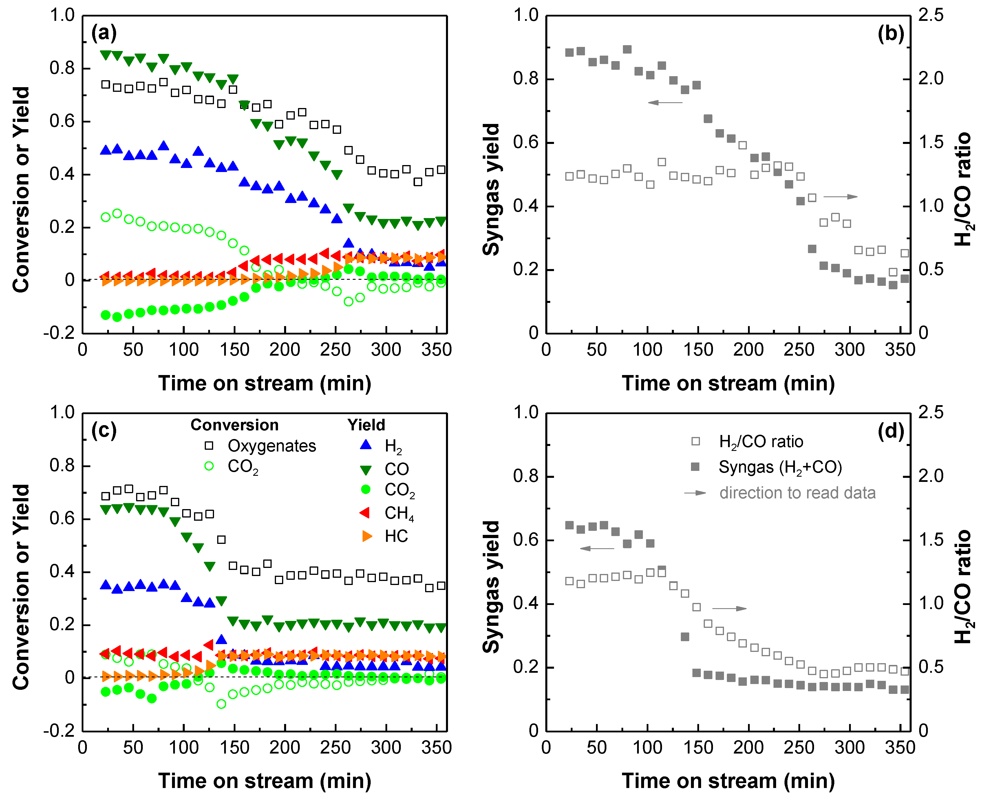
2.1. Performance of the Rh Catalyst in Bio-Oil Reforming

Figure 1 shows the performance of the Rh/ZDC catalyst in the CSDR of bio-oil at 700 °C in two successive reactions with a catalyst regeneration in between. The performance is analyzed in terms of the evolution over time on stream of the product yields (Figure 1a for the reaction with fresh catalyst (first reaction) and Figure 1c for the reaction with the regenerated catalyst (second reaction)) and syngas yield or H2/CO ratio (Figure 1b and Figure 1d for the first and second reactions, respectively). In these data, the oxygenate conversion is estimated as the total yield of the carbon gaseous products (sum of all carbonaceous products after subtracting the molar flow rate of CO2 in the feed), since the estimated coke content and yield are very low according to the TPO analysis shown in the next subsection.
The initial oxygenate conversion is around 0.77 with the fresh catalyst (Figure 1a). This low value evidences that the space time used is low to reach an equilibrium state at these reaction conditions (particularly because of the low S/C ratio), and therefore the maximum product yields may not have been achieved, although this situation is adequate to study the catalyst deactivation. In spite of this, the initial yield values of H2 and CO provide evidence for the high activity of Rh for the bio-oil CSDR, which has also been demonstrated for the OSR of bio-oil [17,18,19]. The comparison of the results in Figure 1a,b with those obtained on a Ni catalyst (Ni/Al2O3 catalyst derived from a NiAl2O4 spinel) under the same conditions [12] reveals that Rh exhibits notably high activity considering that less active sites are actually present in the Rh catalyst (2 wt% Rh vs. 36 wt% Ni). Thus, the initial yield and H2/CO ratio of the syngas are almost 90% and 1.2, respectively, with this Rh catalyst compared to 92% and 0.9 with the Ni catalyst, and the CO2 conversion is 22% against 28%. As a comparison, Figure S1 in the Supplementary Materials shows the results obtained with the Rh/ZDC catalyst at the same conditions as in Figure 1 but without CO2 co-feeding (that is, under SR conditions with a low S/C ratio of 0.5). When comparing the SR and CSDR strategies, a slightly higher oxygenate conversion is observed in the SR reaction (around 80%, Figure S1a) than in the CSDR reaction (Figure 1a). The main difference between both reforming strategies is the increase in the CO yield in the CSDR reaction (from 62% in Figure S1a to 85% in Figure 1a), hence yielding slightly more syngas (near 90% in CSDR reaction, compared to 80% in SR reaction) with a H2/CO ratio of about 1.2 (Figure 1b) in comparison to a H2/CO ratio of 2 for the SR strategy (Figure S1b).
The product distribution (H2, CO, CO2, CH4, and hydrocarbons) observed may be explained considering the DR (Equation (1)) and SR (Equations (3) and (4)) of oxygenates, as well as the catalytic cracking of oxygenates (Equation (5)), as the dominant routes at this high temperature, generating H2 and various gaseous intermediates (CO, CO2, CH4 and hydrocarbons). Then, the SR or DR of CH4 and hydrocarbons (Equations (6)–(9)) generates CO and H2, and the CO2 may be transformed into CO and H2O by the r-WGS reaction (reverse Equation (2)), which is thermodynamically favored at this high temperature and low S/C ratio [4,5]. In spite of its high catalytic activity, the Rh catalyst undergoes deactivation during both the CSDR and SR reactions, which is clearly evidenced by the drop of the H2 and CO yields over time on stream (Figure 1a,b). The activity decay must be mainly attributed to coke formation, which may proceed through the decomposition of oxygenates (Equation (5)), CH4 (Equation (10)), and hydrocarbons (Equation (11)), considering the high temperature (700 °C) and low S/C ratio employed [2]. Simultaneously, coke gasification may take place with CO2 (reverse Equation (12)) or steam (Equation (13)).
Curiously, the evolution of the product yields draws five well-distinguished periods, as has also been observed in the OSR and SR of bio-oil with the same catalyst [19,29] and in Figure S1. Thus, for the CSDR strategy, the first period (around 125 min) shows a quite stable behavior of the catalyst, with high oxygenate conversion and complete conversion of intermediates, CH4, and hydrocarbons, by SR or DR reactions, generating the highest H2 and CO yields with the maximum CO2 conversion boosted by the r-WGS reaction. The second period (~125–175 min) shows a decrease in the H2 and CO yields and in the CO2 conversion and an increase in the CH4 yield, indicating the selective deactivation of the catalyst for the SR or DR of CH4 and the r-WGS reaction. The third period (~175–225 min) describes a pseudo steady state where the conversion of hydrocarbons by SR and DR reactions remains complete. Subsequently, in the fourth period (~225–275 min), the complete catalyst deactivation for the SR and DR reactions of hydrocarbons and oxygenates occurs, evidenced by the sharp decrease in the oxygenate conversion and the H2 and CO yields and increase in the hydrocarbon yield. In this period, the CO2 conversion falls to negative values, reaching a minimum and then increasing up to zero, which is translated into a maximum for the CO2 yield, which suggests a selective deactivation of the DR of hydrocarbons over their SR reaction. The fifth period (above 275 min) presumably corresponds to the yields obtained in the thermal reaction of the bio-oil oxygenates in the presence of both steam and CO2. Consequently, the syngas yield decreases over time following the same trend of these five periods (Figure 1b), whereas the H2/CO ratio is almost constant during the first two periods, slightly increases in the third period, and decays noticeably in the fourth period when the catalyst undergoes complete deactivation.
These periods are also observed in the SR of bio-oil (Figure S1), but in this case CO2 is only a product. Particularly, the CO2 yield increases during the second period (partial deactivation for CH4 conversion) and keeps a higher stable value in the third period in comparison with the first period. This result suggests that the r-WGS reaction (which is thermodynamically favored in these reaction conditions) is also affected by deactivation in the second period. This behavior can also be observed in the CSDR reaction (Figure 1a), though the CO2 yield values are negative. Strikingly, the H2/CO ratio evolution follows a trend similar to that of the CO2 yield, which confirms the partial catalyst deactivation for the r-WGS reaction in the second period.
After the CSDR reaction with the fresh catalyst (Figure 1a), the spent catalyst was regenerated in situ (in the reactor) by coke combustion with air at 600 °C and subsequent reduction in a H2/N2 flow at 700 °C. Upon regeneration (Figure 1c), the catalyst does not fully recover its initial activity, which is particularly evidenced by the absence of two different deactivation periods described above. In turn, the reaction with the regenerated catalyst initiates at a stable period in which hydrocarbons are fully converted by SR or DR reactions, whereas CH4 is not converted (third period in Figure 1a), followed by the complete catalyst deactivation (fourth period in Figure 1a). The syngas yield (Figure 1d) is initially stable and then decreases over time on stream as described by the third and fourth periods in Figure 1b, and the H2/CO ratio also slightly increases and then decreases following the trend described by the CO2 yield. This evidences that the Rh/ZDC catalyst undergoes both reversible and irreversible deactivation. The former is due to the deposition of coke so that the catalyst partially recovers its reforming activity after regeneration. The latter is presumably associated with irreversible changes in the catalyst structure or metal sites. In the following sections, we further investigate the causes of both deactivation phenomena by analyzing the spent catalyst from each reaction test.

2.2. Chacaractarization of Deactivated Catalyst Samples

The coke formed and deposited on the catalyst during each reaction was analyzed by TPO, SEM, and TEM in order to determine its amount and/or nature. Additionally, N2 physisorption was also employed to analyze the effect of coke deposition on the catalyst textural properties. The possible changes in the crystalline structure of the deactivated catalyst were analyzed by XRD analysis. Finally, the H2-TPR profiles of the fresh and regenerated catalyst were compared to analyze the Rh sites. In general, the spent catalyst samples are identified with reference to their reaction test: CSDR-1 for the first CSDR reaction (with the fresh catalyst) and CSDR-2 for the second CSDR reaction (with the regenerated catalyst).

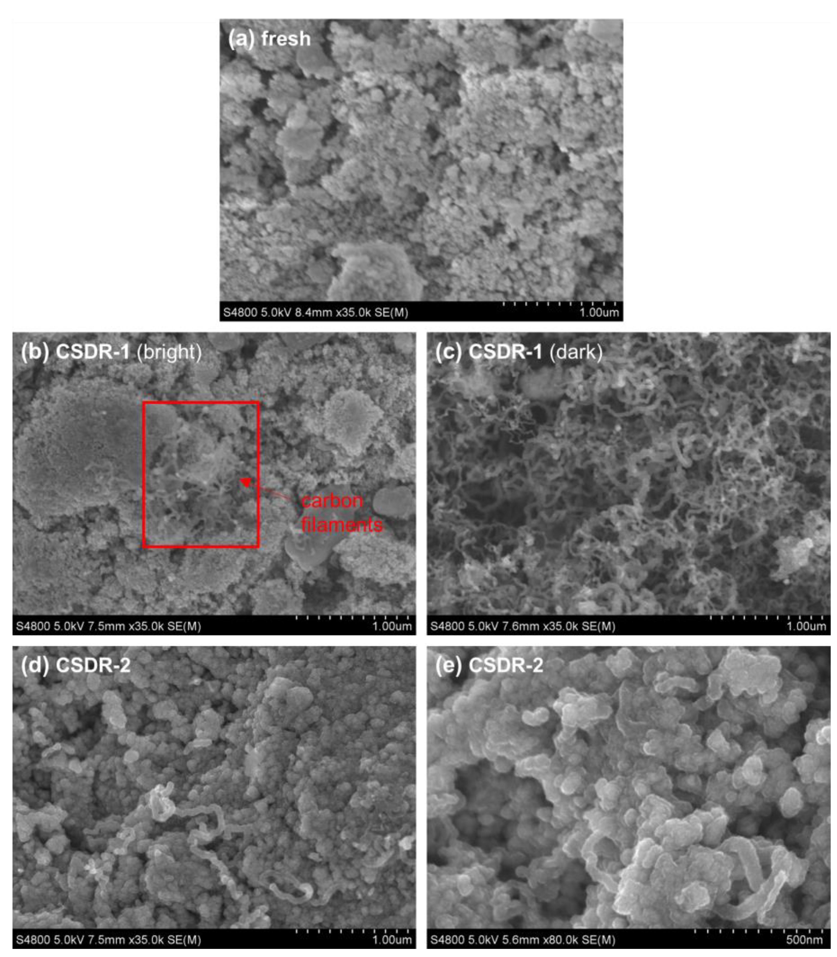
2.2.1. Coke Formation

Figure 2 shows the TPO profiles for the spent catalyst samples, in which the peaks are associated with the combustion of coke. The corresponding coke content (determined by integration of each curve) is indicated next to each profile. The TPO profiles are noticeably different for the two samples, showing combustion peaks centered at different temperatures. The CSDR-1 sample shows two separate peaks centered at 300 and 400 °C, and the CSDR-2 sample shows two overlapping peaks that are approximately centered at 415 and 430 °C. Likewise, the coke content is significantly lower in the CSDR-1 sample (93.6 mg g−1) than in the CSDR-2 sample (302 mg g−1). The temperature position of the combustion peaks may be related to the nature of carbon and to the possible catalytic effect of the catalyst components on the carbon combustion. Thus, the peaks at lower temperatures can be associated with the combustion of poorly developed coke (amorphous carbon, most probably encapsulating Rh sites) and the peaks at higher temperatures are associated with structured coke (carbon nanostructures or turbostratic/graphite carbon) [34,35]. Additionally, both Ce (in the ZDC support) and Rh species can catalyze the carbon combustion [36], which results in combustion peaks at lower temperature than those obtained for Ni catalysts in different bio-oil reforming strategies [12,17,37].
To discern the nature of the coke, the two spent catalyst samples have been analyzed by SEM (with a backscattered electron (BSE) or secondary electron (SE) detector) and TEM. Figure 3 shows the BSE-SEM images for the fresh and spent catalyst samples, which provide qualitative information on the degree of coke deposition on the external surface. Accordingly, the brightness intensity is indicative of the presence of heavy (bright) or light (dark) elements [2,12,35], and for this case, a high or dense presence of coke on the catalyst surface is indicated by darker particles since coke contains the lightest element (C) in these samples in comparison with the catalyst components (Rh, Ce, and Zr). In general, all the particles exhibit relatively bright intensities similar to those of the fresh catalyst (Figure 3a), indicating a poor coke deposition on the catalyst surface or the deposition of carbon with low density, although the CSDR-1 sample also exhibits some dark particles.
Further, to explore the coke deposition, Figure 4 shows the SE-SEM images at higher zooms for all the samples. The Rh/ZDC catalyst shows a granular surface typical of porous materials (in this case the ZDC support), showing some compacted areas. The majority of the particles in the CSDR-1 sample are bright, even though there are some carbon filaments on the surface and some granular and compacted areas that may be the surface of the ZDC support (Figure 4b). The dark particles in the CSDR-1 sample show an abundant presence of carbon filaments (Figure 4c). On the other hand, the CSDR-2 sample shows a smooth granular-like surface (apparently different from that of the catalyst support) with some carbon filaments (Figure 4d), and when this surface is zoomed in upon (Figure 4e), it seems to be a blend of an amorphous mass of carbon with some nanotubes trapped in it.
TEM has been useful to confirm the presence of these carbon types as shown in Figure 5, from which it should be considered that only tiny fragments of the samples can be analyzed without distinguishing between the external/internal surface of the particle. The Rh/ZDC catalyst shows grains of different grey tones, with the darker ones presumably being Rh crystals as this is the densest catalyst component. The CSDR-1 sample shows the presence of both carbon filaments (Figure 5b) and amorphous/turbostratic carbon encapsulating the catalyst components (Figure 5c). On the other hand, the CSDR-2 sample barely shows a mass of carbon covering the catalyst components in spite of having the highest coke content. The difficulty to observe the carbon on this latter sample is perhaps due to its nature, apparently a thin layer of carbon mass covering the entire surface evenly, as well as the limitation of the technique to analyze this type of solid.
The textural properties of the fresh and spent catalyst samples (Table 1) evidence the impact of coke deposition. The formation of both carbon filaments and amorphous carbon in the CSDR reaction with the fresh catalyst (CSDR-1 sample) causes the BET surface area to decrease by 33%, with a strong impact on the microporous surface area and on the volume, which both decrease by about 62%. On the other hand, the formation of a blend of amorphous/turbostratic carbon and small carbon filaments in the CSDR reaction with the regenerated catalyst (CSDR-2 sample) causes a strong decrease in the BET surface area (about 74%) and in the total volume of pores (by 83%) without affecting the microporous surface area. This suggests that in the reaction with the fresh catalyst, the amorphous carbon may be deposited on the microporous surface, whereas all the carbon is deposited on the external surface of the catalyst particles in the reaction with the regenerated catalyst. It should be noted that the reduced specific surface is a notable limitation of the CeO2 support, as pointed out in the literature [28], and it is more pronounced in this reaction due to coke deposition.

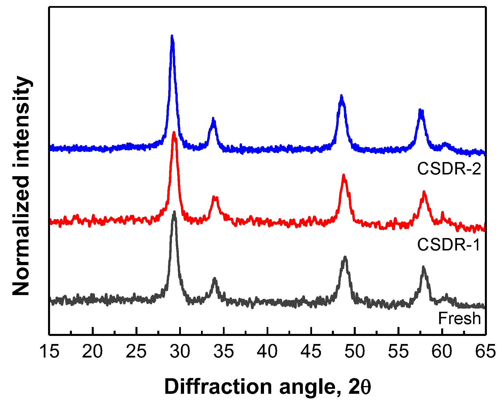
2.2.2. Characterization of Catalyst Structure and Rh Sites

The XRD analysis of the fresh and spent catalyst samples (Figure 6) evidences no changes in the crystalline properties of the ZDC support, as all the diffraction peaks observed are similar among all the samples and correspond to the ZDC structure [38]. No diffraction peaks are observed for Rh species, since the Rh content is low (2 wt%) and it is most probably well dispersed on the support. Likewise, the formation of crystalline carbon is not evidenced either, as no diffraction peaks are detected for carbon (15–30° range), which may also be due to the low coke content.
To understand the irreversible catalyst deactivation in the CSDR reaction, the H2-TPR profiles of the fresh and regenerated catalyst are analyzed (Figure 7), providing insights on the Rh sites. The reducibility of these sites is related to the interaction between the active phase and the support, which in the case of Rh is strongly dependent on the properties of the latter [27]. For the regenerated catalyst, the CSDR-1 sample was subjected to combustion (TPO) to remove the coke and then to a H2-TPR measurement to observe the reducibility of Rh species. In general, both H2-TPR profiles are similar, showing a broad reduction peak between 50 and 125 °C and a shoulder between 125 and 200 °C, which are similar to the H2-TPR profiles of Rh catalysts reported in the literature [19,29,39]. To better distinguish the reduction of different Rh species, the H2-TPR profiles were deconvoluted into three Gauss bands that correspond to the reduction of three Rh species (identified as Rh-1, Rh-2, and Rh-3) possibly indicating different interactions with the ZDC support. The Rh-1 and Rh-2 bands may be associated with the reduction of Rh3+ species on the support [39], likely having different interactions with the ZDC support (weak/strong interactions). Those Rh3+ species with a weak support interaction would be reduced easily, and therefore they would be associated with the Rh-1 band. The Rh-3 band is associated with the reduction of Rh species strongly interacting with the ZDC support, such as Rh3+ species in the CeO2 lattice [39]. The deconvolution also shows how the relative portions of the different Rh species change after catalyst regeneration (Figure 7b) in comparison with the fresh catalyst (Figure 7a). Thus, the fraction of Rh-2 species notably increases after the regeneration, which may suggest that the Rh3+ species have stronger interactions with the support. This would support the possible encapsulation of Rh sites, causing a decrease in their activity (particularly for the CH4 reforming and CO2 conversion).
The textural properties of the regenerated catalyst (Table 1) evidence that the BET specific surface area is not fully recovered, though the microporous specific surface area is fully restored after regeneration.

3. Discussion

The results in Figure 1 show that the commercial Rh/ZDC catalyst is highly active for the bio-oil CSDR, though it undergoes reversible and irreversible deactivation. The reversible deactivation is associated with the coke deposition as demonstrated in other reforming strategies of a real bio-oil feed using Rh or Ni catalysts [29,40], whereas the irreversible deactivation is similar to that observed for the OSR and SR of a real bio-oil with a Rh catalyst, which is associated with irreversible changes in the catalyst structure [19,29]. Thus, the low steam concentration in the bio-oil CSDR (steam is formed from the intrinsic H2O content in the bio-oil) did not lessen the irreversible deactivation as it was hypothesized. In the present work, we have further observed that the coke formation in the first reaction (with the fresh catalyst) and second reaction (with the regenerated catalyst) is quite different, which is a consequence of the irreversible deactivation. The lower activity of the regenerated catalyst (unable to convert CH4) leads to a faster coke deactivation (Figure 1c) with a higher coke deposition (three times more than in the reaction with the fresh catalyst) that promptly blocks all the catalyst surface (as revealed by the low BET surface area of CSDR-2 sample in Table 1). The analysis of Figure 2, Figure 3, Figure 4 and Figure 5 and Table 1 evidences that an apparent mass of amorphous carbon combusting at 300 °C and carbon filaments combusting at 400 °C are formed in the reaction with the fresh catalyst (CSDR-1 sample), whereas an apparent blend of amorphous/turbostratic carbon and carbon filaments, covering the entire catalyst surface and combusting at 415–430 °C, is formed in the reaction with the regenerated catalyst (CSDR-2 sample). The lower temperatures required to combust the coke in comparison to the expected combustion temperatures for the types of carbons observed in the bio-oil reforming processes over other catalysts [12,17,37] can be attributed to the catalytic effect of the Ce and Rh species on the carbon combustion. This effect is more evident in the coke combustion from the reaction with the fresh catalyst because the coke deposition causes low blockage of the porous surface (Table 1), enabling good contact between O2 and the catalyst surface during the combustion. Conversely, the higher combustion temperature of the coke formed in the reaction with the regenerated catalyst may be explained by the coke refractoriness and the poor contact between O2 and the catalytic species during the combustion due to the higher pore blockage (Table 1), lessening the catalytic effect of Ce and Rh on the carbon combustion.
The irreversible deactivation selectively affects the CH4 reforming reactions (DR and SR) and also partially the r-WGS reaction, which suggests that the sites that activate CH4 and CO2 are irreversibly modified in a given moment during the reaction with the fresh catalyst and/or the regeneration process. In resemblance with other works [19,29], the irreversible deactivation of a similar Rh/ZDC catalyst was detected to occur during the reaction of the OSR of bio-oil when the catalyst loses its activity for the CH4 conversion. This deactivation was attributed to the aging of the ZDC support at high temperatures (700 °C, the same temperature used in this work) and presence of steam, which was evidenced by the loss of textural properties and interpreted as a collapse of the narrower pores occluding some Rh sites. In this present work, we have also evidenced the loss of textural properties after the catalyst regeneration (Table 1), directly observing an irreversible loss of surface area and an increase in the average pore size, which may be congruent with the collapse of some pores. This can also be supported by the observations of the SEM analysis (Figure 5b), in which an apparent increase in the compacted areas after the reaction with the fresh catalyst (CSDR-1 sample) can be interpreted as a reduction in the porosity. We have further analyzed the changes in the Rh sites by H2-TPR (Figure 7), possibly suggesting partial encapsulation of Rh3+ species with the ZDC support, which apparently reduces the activity for the bio-oil CSDR process (unable to activate CH4 and CO2). It is worth mentioning that Rh sintering was not evidenced by the TEM images, since the Rh nanoparticles have similar sizes for the fresh and spent catalysts. Likewise, Rh sintering is not significant for this catalyst in the SR of bio-oil at 700 °C [29], whereas it starts to be slightly significant in the OSR of bio-oil at 750 °C [19], and therefore we may disregard the occurrence of Rh sintering in the bio-oil CSDR at 700 °C.
It is not straightforward to attribute the irreversible deactivation of this catalyst to the irreversible modifications of a sole catalyst component (either the metal (Rh) or the support (ZDC)). Focusing on Rh, the existence of this irreversible deactivation selectively affecting the CH4 reforming was also observed in the SR of bio-oil over two different Rh catalysts, one supported on La2O3–αAl2O3 (Rh/LaAl) and another on ZDC (the one used in this work, Rh/ZDC), as shown in Figures S2 and S3 (Supplementary Materials) [30]. Both catalysts showed the deactivation periods observed for the bio-oil CSDR in this present work, with the Rh/LaAl catalyst being more stable than the Rh/ZDC catalyst in the SR reaction with each fresh catalyst. Nevertheless, the Rh/LaAl catalyst suffers a more severe irreversible deactivation than the commercial Rh/ZDC catalyst, evidenced by the shorter duration of the initial stable period in the SR reactions with the regenerated catalysts. This comparison suggests that the irreversible deactivation observed in the reforming of bio-oil may also be an intrinsic characteristic of Rh regardless of the support.
Regarding the support, the role of CeO2 in the catalyst deactivation can be explained by various phenomena. Primarily, it is important to consider that the CeO2 structure may collapse when subject to high temperature treatments causing the loss of surface area [41,42], which is one of the observations of our present work, and it has been interpreted to cause an occlusion of Rh sites. However, another close effect would be the phenomenon of encapsulation of noble metals by CeO2 at high temperatures, which is recognized as a cause of irreversible deactivation [31,32,33]. The possible encapsulation of Rh sites may be evidenced by the increase in the interaction between Rh sites and the ZDC support as demonstrated by the H2-TPR analysis in this present work. Curiously, this phenomenon is a method for catalyst preparation [43], yet it requires the metal does not lose its catalytic properties. Nevertheless, our results suggest that the Rh sites may be irreversibly modified and partially lose their catalytic properties when they are encapsulated by ZDC support. Considering that Rh sites have specific surfaces that are active for the CH4 or CO2 activation [44], this partial irreversible activity loss may occur through a simple preferential encapsulation of CeO2 on the Rh surfaces that are active for the CH4 and CO2 activations, leading to the irreversible blockage of those specific active sites. Another possibility is a modification of the Rh crystallographic properties, thus changing the Rh active surfaces. For example, the loss of activity for the CO2 methanation with a Ni/CeO2 catalyst was attributed to the modification of Ni nanocrystals from hexagons to quasi-spheres upon partial encapsulation by CeO2 [45]. As previously commented, this encapsulation and modification of Rh sites would occur in the first period of the reaction with the fresh catalyst and therefore is favored under reaction conditions (presence of various reactant species) as the previous reduction treatment (with H2) seems not to have a significant effect on the Rh sites. Moreover, the modification of the temperature of catalyst regeneration by coke combustion will require detailed studies, as it cannot be ruled out that the catalyst sintering will be affected by the generation of hot spots (favored by the oxidizing activity of the catalyst).

4. Materials and Methods

The Rh supported on zirconium-doped ceria (Rh/ZDC) catalyst, with 2 wt% Rh, was supplied by Fuel Cell Materials. The catalyst samples (fresh, spent, and regenerated) were analyzed using N2 physisorption, temperature-programmed reduction (H2-TPR), temperature-programmed oxidation (TPO), scanning electron microscopy (SEM) using backscattered electron (BSE) or secondary electron (SE) detectors, transmission electron microscopy (TEM), or X-ray diffraction (XRD).
The N2 physisorption equilibria measurements were carried out in Micromeritics ASAP 2010 analyzer at 77 K, and the data were treated with the BET, t-plot, and BJH methods to determine the specific surface area, volume, and average pore diameter. The H2-TPR was performed in a TA Instruments SDT 650 thermogravimetric analyzer, and the procedure consisted of reducing in a H2/Ar/N2 flow (100 mL min−1) while increasing the temperature at 5 °C min−1 from 25 °C to 700 °C. Prior to the reduction, the deposited coke was removed by combustion in an O2/N2 flow at 700 °C. The TPO measurements were carried out in a thermogravimetric analyzer (TA Instruments, Q5000, New Castle, DE, USA) coupled with a mass spectrometer (Balzers Instruments, ThermoStar GSD 300, Balzers, Liechtenstein) for monitoring the CO2 signal, and the procedure consisted of heating up the sample at 5 °C min−1 up to 700 °C in a O2/N2 flow. The SEM images were collected with a field emission gun scanning electron microscope (Hitachi, S-4800 N, Santa Clara, CA, USA) with an accelerating voltage of 5 kV and a SE detector, and a microscope with an accelerating voltage of 15 kV using a BSE detector (Hitachi, S-3400N, Santa Clara, CA, USA). For the TEM analysis, the samples were crushed and dispersed in ethanol and a drop of the dispersion was placed on a grid covered with a carbon film, and, after allowing to dry, the TEM images were obtained with a transmission electron microscope (JEOL, 1400 Plus, Tokyo, Japan) using an accelerating voltage of 100 kV. The XRD patterns were carried out in a Bruker D8 Advance diffractometer (Tokyo, Japan) with a Cu Kα1 radiation (wavelength of 1.5406 Å) corresponding to an X-ray tube with a Cu anticathode.
The bio-oil was supplied by BTG Bioliquids BV (Enschede, The Netherlands) and was obtained by flash pyrolysis of pine sawdust in a plant provided with a conical rotatory reactor. The chemical composition was determined by gas chromatography/mass spectrometry analysis (Shimadzu, GC/MS-QP2010S, Carlsbad, CA, USA) provided with a BPX-5 column (length of 50 m, diameter of 0.22 m and thickness of 0.25 μm) and a mass selective detector. The identification of the compounds was carried out by comparison with the pattern spectra available in the NIST 147 and NIST 27 libraries. The detailed composition is described elsewhere [46], mainly containing acetic acid (16.6 wt%), levoglucosane (11.1 wt%), guaiacol (11.1 wt%), and acetol (9.4 wt%). The water content (23 wt%) was determined by Karl Fischer volumetric valorization (Metrohm, KF Titrino Plus 870, Herisau, Switzerland). The empirical formula (C3.9H6.9O2.9) was obtained by CHO analysis in a Leco CHN-932 analyzer (water-free basis).
The SR and CSDR reaction tests were carried out in a continuous two-unit reaction equipment (MicroActivity Reference from PID Eng&Tech, Madrid, Spain) as described elsewhere [12]. The first unit is a U-shaped steel tube for the vaporization of bio-oil and the controlled deposition of pyrolytic lignin (PL) formed by repolymerization of some oxygenates (mainly phenolic compounds) during the vaporization of bio-oil at 500 °C [47]. The vaporized oxygenates enter the second unit, consisting of a stainless steel fluidized bed reactor. The reaction components (H2, CO, CO2, H2O, CH4, light hydrocarbons C2–C4) were analyzed by gas chromatography (Varian CP-490 Micro GC with three chromatographic columns, described elsewhere [48]) connected to the reactor through an insulated line (130 °C) to avoid condensation. The bio-oil was fed at 0.06 mL min−1 by using a Harvard Apparatus 22 injection pump and was mixed with CO2 and/or N2 at the entrance of the first unit. The catalyst was mixed with SiC to provide a minimum height/diameter ratio of 2 in the reactor and to improve the heat dissipation. The space time was defined as the ratio between the catalyst mass and mass flow rate of oxygenates in the bio-oil, and the value was set at 0.125 gcatalyst h (goxygenates)−1. This low value is adequate for the study of catalyst deactivation in a short reaction time, which is required to avoid the plugging of the first unit (for bio-oil vaporization) by accumulation of the PL. All the reaction tests were carried out at 700 °C. Prior to each reaction, the catalyst was reduced in the reactor itself at 700 °C under H2/N2 flow (10% H2). For the SR reaction, bio-oil was only mixed with N2, and the S/C ratio is that provided by the H2O content in the bio-oil (S/C = 0.5). For the CSDR reaction, the bio-oil was mixed with both CO2 and N2, with a CO2/C ratio of 0.6 and S/C ratio of 0.5 (provided by the H2O content in the bio-oil). N2 was used as an internal pattern and the flow rates of the reaction components were calculated using the chromatographic data. The deactivated catalyst was regenerated in the reactor itself by coke combustion in air stream (100 mL min−1) at 600 °C for 4 h, which assured total coke removal. A second reaction was performed with the regenerated catalyst under the same conditions as the first reaction to analyze the activity recovery.
The yields of products (Equations (14)–(17)) were calculated referring to the moles of C contained in the bio-oil, rather than the total carbon supplied (from both the bio-oil and CO2) [5,12], which helps to relate the yields to the conversion of oxygenates in the bio-oil. Consequently, in the calculation of the CO2 yield, it is necessary to substract the moles of CO2 fed with the bio-oil to avoid overestimating its yield relative to the oxygenates supplied.
Y H 2 = F H 2 , o u t F 0 H 2
Y i = F i , o u t F C , i n   for   i = CO ,   CH 4 ,   hydrocarbons
Y C O 2 = F C O 2 , o u t F C O 2 , i n F C , i n
Y s y n g a s = F H 2 , o u t + F C O , o u t F 0 s y n g a s
In the above equations, FH2,out is the molar flow rate of H2 in the outlet stream, Fi,out is the molar flow rate in C basis of the carbonaceous products (except CO2) in the outlet stream, FC,in is the molar flow rate of oxygenates in C basis in the inlet stream (subtracting the C deposited as PL), FCO2,out and FCO2,in are the molar flow rate of CO2 in the reactor outlet and inlet, respectively, and FCO,out is the molar flow rate of CO in the outlet stream. Additionally, F0H2 and F0syngas are the stoichiometric amounts of H2 and syngas, respectively, that would be formed per mole of C in the oxygenate feed in the SR reaction, which, according to the stoichiometry of Equations (4) (for H2) and (3) (for syngas), are:
F 0 H 2 = F 0 s y n g a s = 2 n + m 2 k n F C , i n ,
where n, m, and k are the atoms in the generic empirical formula for oxygenates (CnHmOk).
The CO2 conversion was calculated as:
X C O 2 = F C O 2 , i n F C O 2 , o u t F C O 2 , i n ,
The conversion of oxygenates entering the reforming reactor is estimated by the total yield of carbonaceous gas products
X oxygenates = F C ,   out F CO 2 , in F in = Y i
where FC,out is the total molar flow rate in C basis of the gas carbon products in the outlet stream. The above definition can be used when the coke deposition is low and therefore the coke yield can be considered negligible (as occurs in the conditions of this study).

5. Conclusions

The Rh/ZDC catalyst is highly active for the combined steam/dry reforming of bio-oil, producing a syngas yield close to 90% with a H2/CO ratio of 1.2 (suitable for synthesis of useful chemicals) at 700 °C with CO2/CO ratio of 0.6, S/C ratio of 0.5 (as a result of the water content in the bio-oil), and low space time of 0.125 gcatalyst h (goxygenates)−1. However, it undergoes deactivation, evidenced by the decrease in syngas yields over time on stream in two well-distinguished deactivation periods. The first deactivation period involves the complete loss of activity for CH4 reforming reactions (both SR or DR) and partially for the r-WGS reaction. The second period leads to the complete catalyst deactivation for the reforming of oxygenates and hydrocarbons. The first period corresponds to an irreversible deactivation, and, therefore, it is not observed after catalyst regeneration, whereas the second period is a reversible deactivation, as the activity of the catalyst at the beginning of this period is recovered after the regeneration of the catalyst.
The reversible deactivation is associated with the formation and deposition of coke blocking access to the active sites, and its removal by combustion allows for the catalyst to partially recover its activity. The irreversible catalyst deactivation is generated by changes to the Rh sites and to the textural properties of the ZDC support. Thus, the regenerated catalyst does not recover the specific surface area, which is probably a consequence of the collapse of some pores due to the high temperatures during the reaction and regeneration. Likewise, the H2-TPR of the regenerated catalyst evidences a change in the Rh species, increasing those with high interactions with the support, which possibly suggests the partial encapsulation of Rh sites by CeO2.
This work corroborates the irreversible deactivation of Rh catalysts for different reforming strategies of complex feeds, such as bio-oil, which has also been observed for other Rh supported catalysts. Thus, although Rh catalysts are very active, their use for bio-oil reforming may not be practical because they might not meet the need for a good regeneration capacity due to irreversible deactivation.

Supplementary Materials

The following supporting information can be downloaded at: https://www.mdpi.com/article/10.3390/catal14090571/s1, Figure S1: Performance of the Rh/ZDC catalyst in the SR of bio-oil at 700 °C, H2O/C ratio of 0.5/1, and space time of 0.125 gcatalyst h (goxygenates)−1: (a) Evolution of the product yields over time on stream; (b) evolution of the syngas yield and H2/CO ratio over time on stream; Figure S2: Evolution with time on stream (TOS) of bio-oil conversion and H2 yield in two reaction steps of raw bio-oil SR with intermediate regeneration (coke combustion with air) over Rh catalysts supported on zirconia-doped ceria (ZDC) or La2O3-αAl2O3 (LaAl). Reaction conditions: 700°C; S/C, 6; 0.15 gcatalyst h (goxygenates)−1; Figure S3: Evolution with time on stream (TOS) of CH4 and hydrocarbons (HCs) yields in two reaction steps of raw bio-oil SR with intermediate regeneration (coke combustion with air) over Rh catalyst supported on La2O3-αAl2O3. Reaction conditions: 700 °C; S/C, 6; space time, 0.15 gcatalyst h (goxygenates)−1.

Author Contributions

Conceptualization, J.V., J.B. and A.G.G.; methodology, L.L.; formal analysis, L.L. and J.V.; investigation, L.L. and J.V.; resources, A.G.G.; data curation, L.L. and A.G.G.; writing—original draft preparation, J.V. and G.E.; writing—review and editing, A.R., J.B. and A.G.G.; visualization, L.L., J.V. and G.E.; supervision, A.R. and A.G.G.; project administration, A.G.G.; funding acquisition, A.G.G. All authors have read and agreed to the published version of the manuscript.

Funding

This research was funded by the Ministry of Science and Innovation of the Spanish Government, grant number PID2021-127005OB-I00, funded by MCIN/AEI/10.13039/501100011033 and by “ERDF A way of making Europe”; the European Commission (HORIZON H2020-MSCA RISE 2018), contract number 823745; the Department of Education, Universities and Investigation of the Basque Government, grant number IT1645-22 and PhD grant number PRE_2021_2_0147 for L.L.

Data Availability Statement

Available upon request.

Acknowledgments

The authors are thankful for the technical and human support provided by SGIker (UPV/EHU/ERDF, EU).

Conflicts of Interest

The authors declare no conflicts of interest.

References

  1. Bachmann, M.; Völker, S.; Kleinekorte, J.; Bardow, A. Syngas from What? Comparative Life-Cycle Assessment for Syngas Production from Biomass, CO2, and Steel Mill Off-Gases. ACS Sustain. Chem. Eng. 2023, 11, 5356–5366. [Google Scholar] [CrossRef]
  2. García-Gómez, N.; Valecillos, J.; Valle, B.; Remiro, A.; Bilbao, J.; Gayubo, A.G. Combined effect of bio-oil composition and temperature on the stability of Ni spinel derived catalyst for hydrogen production by steam reforming. Fuel 2022, 326, 124966. [Google Scholar] [CrossRef]
  3. Baloch, H.A.; Nizamuddin, S.; Siddiqui, M.T.H.; Riaz, S.; Jatoi, A.S.; Dumbre, D.K.; Mubarak, N.M.; Srinivasan, M.P.; Griffin, G.J. Recent advances in production and upgrading of bio-oil from biomass: A critical overview. J. Environ. Chem. Eng. 2018, 6, 5101–5118. [Google Scholar] [CrossRef]
  4. Landa, L.; Remiro, A.; De Torre, R.; Aguado, R.; Bilbao, J.; Gayubo, G. Global vision from the thermodynamics of the effect of the bio-oil composition and the reforming strategies in the H 2 production and the energy requirement. Energy Convers. Manag. 2021, 239, 114181. [Google Scholar] [CrossRef]
  5. Landa, L.; Remiro, A.; Valecillos, J.; Bilbao, J.; Gayubo, A.G. Thermodynamic study of the CO2 valorization in the combined steam-dry reforming of bio-oil into syngas. J. CO2 Util. 2023, 72, 102503. [Google Scholar] [CrossRef]
  6. Zhao, Z.; Situmorang, Y.A.; An, P.; Chaihad, N.; Wang, J.; Hao, X.; Xu, G.; Abudula, A.; Guan, G. Hydrogen production from catalytic steam reforming of bio-oils: A critical review. Chem. Eng. Technol. 2020, 43, 625–640. [Google Scholar] [CrossRef]
  7. Silva, J.; Rocha, C.; Soria, M.A.; Madeira, L.M. Catalytic Steam Reforming of Biomass-Derived Oxygenates for H2 Production: A Review on Ni-Based Catalysts. ChemEngineering 2022, 6, 39. [Google Scholar] [CrossRef]
  8. Pafili, A.; Charisiou, N.D.; Douvartzides, S.L.; Siakavelas, G.I.; Wang, W.; Liu, G.; Papadakis, V.G.; Goula, M.A. Recent progress in the steam reforming of bio-oil for hydrogen production: A review of operating parameters, catalytic systems and technological innovations. Catalysts 2021, 11, 1526. [Google Scholar] [CrossRef]
  9. Setiabudi, H.D.; Aziz, M.A.A.; Abdullah, S.; Teh, L.P.; Jusoh, R. Hydrogen production from catalytic steam reforming of biomass pyrolysis oil or bio-oil derivatives: A review. Int. J. Hydrogen Energy 2020, 45, 18376–18397. [Google Scholar] [CrossRef]
  10. Zhang, C. Review of catalytic reforming of biomass pyrolysis oil for hydrogen production. Front. Chem. 2022, 10, 1–6. [Google Scholar] [CrossRef]
  11. Kumar, R.; Strezov, V. Thermochemical production of bio-oil: A review of downstream processing technologies for bio-oil upgrading, production of hydrogen and high value-added products Oil in Water. Renew. Sustain. Energy Rev. 2021, 135, 110152. [Google Scholar] [CrossRef]
  12. Landa, L.; Remiro, A.; Valecillos, J.; Bilbao, J.; Gayubo, A.G. Syngas production through combined steam-dry reforming of raw bio-oil over a NiAl2O4 spinel derived catalyst. J. CO2 Util. 2023, 78, 102637. [Google Scholar] [CrossRef]
  13. Hu, X.; Lu, G. Bio-oil steam reforming, partial oxidation or oxidative steam reforming coupled with bio-oil dry reforming to eliminate CO2 emission. Int. J. Hydrogen Energy 2010, 35, 7169–7176. [Google Scholar] [CrossRef]
  14. Qingli, X.; Peng, F.; Wei, Q.; Kai, H.; Shanzhi, X.; Yongjie, Y. Catalyst deactivation and regeneration during CO2 reforming of bio-oil. Int. J. Hydrogen Energy 2019, 44, 10277–10285. [Google Scholar] [CrossRef]
  15. Rioche, C.; Kulkarni, S.; Meunier, F.C.; Breen, J.P.; Burch, R. Steam reforming of model compounds and fast pyrolysis bio-oil on supported noble metal catalysts. Appl. Catal. B Environ. 2005, 61, 130–139. [Google Scholar] [CrossRef]
  16. Rennard, D.; French, R.; Czernik, S.; Josephson, T.; Schmidt, L. Production of synthesis gas by partial oxidation and steam reforming of biomass pyrolysis oils. Int. J. Hydrogen Energy 2010, 35, 4048–4059. [Google Scholar] [CrossRef]
  17. Remiro, A.; Arandia, A.; Bilbao, J.; Gayubo, A.G. Comparison of Ni based and Rh based catalyst performance in the oxidative steam reforming of raw bio-oil. Energy Fuels 2017, 31, 7147–7156. [Google Scholar] [CrossRef]
  18. Arandia, A.; Remiro, A.; Oar-Arteta, L.; Bilbao, J.; Gayubo, A.G. Reaction conditions effect and pathways in the oxidative steam reforming of raw bio-oil on a Rh/CeO2-ZrO2 catalyst in a fluidized bed reactor. Int. J. Hydrogen Energy 2017, 42, 29175–29185. [Google Scholar] [CrossRef]
  19. Remiro, A.; Arandia, A.; Oar-Arteta, L.; Bilbao, J.; Gayubo, A.G. Stability of a Rh/CeO2-ZrO2 Catalyst in the Oxidative Steam Reforming of Raw Bio-oil. Energy Fuels 2018, 32, 3588–3598. [Google Scholar] [CrossRef]
  20. Iojoiu, E.E.; Domine, M.E.; Davidian, T.; Guilhaume, N.; Mirodatos, C. Hydrogen production by sequential cracking of biomass-derived pyrolysis oil over noble metal catalysts supported on ceria-zirconia. Appl. Catal. Gen. 2007, 323, 147–161. [Google Scholar] [CrossRef]
  21. Domine, M.E.; Iojoiu, E.E.; Davidian, T.; Guilhaume, N.; Mirodatos, C. Hydrogen production from biomass-derived oil over monolithic Pt- and Rh-based catalysts using steam reforming and sequential cracking processes. Catal. Today 2008, 133–135, 565–573. [Google Scholar] [CrossRef]
  22. Ranjekar, A.M.; Yadav, G.D. Dry reforming of methane for syngas production: A review and assessment of catalyst development and efficacy. J. Indian Chem. Soc. 2021, 98, 100002. [Google Scholar] [CrossRef]
  23. Wang, C.; Wang, Y.; Chen, M.; Liang, D.; Yang, Z.; Cheng, W.; Tang, Z.; Wang, J.; Zhang, H. Recent advances during CH4 dry reforming for syngas production: A mini review. Int. J. Hydrogen Energy 2021, 46, 5852–5874. [Google Scholar] [CrossRef]
  24. Fan, M.S.; Abdullah, A.Z.; Bhatia, S. Catalytic technology for carbon dioxide reforming of methane to synthesis gas. ChemCatChem 2009, 1, 192–208. [Google Scholar] [CrossRef]
  25. da Silva, A.M.; de Souza, K.R.; Jacobs, G.; Graham, U.M.; Davis, B.H.; Mattos, L.V.; Noronha, F.B. Steam and CO2 reforming of ethanol over Rh/CeO2 catalyst. Appl. Catal. B Environ. 2011, 102, 94–109. [Google Scholar] [CrossRef]
  26. Díaz López, E.; Comas-Vives, A. CO2 activation dominating the dry reforming of methane catalyzed by Rh(111) based on multiscale modelling. Catal. Sci. Technol. 2023, 13, 7162–7171. [Google Scholar] [CrossRef]
  27. Kartavova, K.E.; Mashkin, M.Y.; Kostin, M.Y.; Finashina, E.D.; Kalmykov, K.B.; Kapustin, G.I.; Pribytkov, P.V.; Tkachenko, O.P.; Mishin, I.V.; Kustov, L.M.; et al. Rhodium-Based Catalysts: An Impact of the Support Nature on the Catalytic Cyclohexane Ring Opening. Nanomaterials 2023, 13, 936. [Google Scholar] [CrossRef]
  28. Mashkin, M.Y.; Tedeeva, M.A.; Fedorova, A.A.; Fatula, E.R.; Egorov, A.V.; Dvoryak, S.V.; Maslakov, K.I.; Knotko, A.V.; Baranchikov, A.E.; Kapustin, G.I.; et al. Synthesis of CexZr1-xO2/SiO2 supports for chromium oxide catalysts of oxidative dehydrogenation of propane with carbon dioxide. J. Chem. Technol. Biotechnol. 2023, 98, 1247–1259. [Google Scholar] [CrossRef]
  29. Remiro, A.; Ochoa, A.; Arandia, A.; Castaño, P.; Bilbao, J.; Gayubo, A.G. On the dynamics and reversibility of the deactivation of a Rh/CeO2–ZrO2 catalyst in raw bio-oil steam reforming. Int. J. Hydrogen Energy 2019, 44, 2620–2632. [Google Scholar] [CrossRef]
  30. García-Gómez, N.; Valle, B.; Remiro, A.; Bilbao, J.; Gayubo, A.G. The effect of the support in the deactivation and regeneration of Rh catalysts used in the steam reforming of bio-oil. In Proceedings of the 3rd International Congress Chemistry & Environment ANQUE-ICCE3, Santander, Spain, 19–21 June 2019. [Google Scholar]
  31. Machida, M.; Yoshida, H.; Kamiuchi, N.; Fujino, Y.; Miki, T.; Haneda, M.; Tsurunari, Y.; Iwashita, S.; Ohta, R.; Yoshida, H.; et al. Thermal Aging of Rh/ZrO2-CeO2 Three-Way Catalysts under Dynamic Lean/Rich Perturbation Accelerates Deactivation via an Encapsulation Mechanism. ACS Catal. 2023, 13, 3806–3814. [Google Scholar] [CrossRef]
  32. Machida, M.; Yoshida, H.; Kamiuchi, N.; Fujino, Y.; Miki, T.; Haneda, M.; Tsurunari, Y.; Iwashita, S.; Ohta, R.; Yoshida, H.; et al. Rh Nanoparticles Dispersed on ZrO2-CeO2 Migrate to Al2O3 Supports to Mitigate Thermal Deactivation via Encapsulation. ACS Appl. Nano Mater. 2023, 6, 9805–9815. [Google Scholar] [CrossRef]
  33. Craciun, R.; Daniell, W.; Knözinger, H. The effect of CeO2 structure on the activity of supported Pd catalysts used for methane steam reforming. Appl. Catal. A Gen. 2002, 230, 153–168. [Google Scholar] [CrossRef]
  34. He, L.; Liao, G.; Li, H.; Ren, Q.; Hu, S.; Han, H.; Xu, J.; Jiang, L.; Su, S.; Wang, Y.; et al. Evolution characteristics of different types of coke deposition during catalytic removal of biomass tar. J. Energy Inst. 2020, 93, 2497–2504. [Google Scholar] [CrossRef]
  35. García-Gómez, N.; Valecillos, J.; Remiro, A.; Valle, B.; Bilbao, J.; Gayubo, A.G. Effect of reaction conditions on the deactivation by coke of a NiAl2O4 spinel derived catalyst in the steam reforming of bio-oil. Appl. Catal. B Environ. 2021, 297, 120445. [Google Scholar] [CrossRef]
  36. Gong, X.; Guo, Z.; Wang, Z. Reactivity of pulverized coals during combustion catalyzed by CeO2 and Fe2O3. Combust. Flame 2010, 157, 351–356. [Google Scholar] [CrossRef]
  37. Arandia, A.; Remiro, A.; García, V.; Castaño, P.; Bilbao, J.; Gayubo, A. Oxidative Steam Reforming of Raw Bio-Oil over Supported and Bulk Ni Catalysts for Hydrogen Production. Catalysis 2018, 8, 322. [Google Scholar] [CrossRef]
  38. Sagar Vijay Kumar, P.; Suresh, L.; Vinodkumar, T.; Reddy, B.M.; Chandramouli, G.V.P. Zirconium Doped Ceria Nanoparticles: An Efficient and Reusable Catalyst for a Green Multicomponent Synthesis of Novel Phenyldiazenyl-Chromene Derivatives Using Aqueous Medium. ACS Sustain. Chem. Eng. 2016, 4, 2376–2386. [Google Scholar] [CrossRef]
  39. Fedorova, E.A.; Kardash, T.Y.; Kibis, L.S.; Stonkus, O.A.; Slavinskaya, E.M.; Svetlichnyi, V.A.; Pollastri, S.; Boronin, A.I. Unraveling the low-temperature activity of Rh-CeO2 catalysts in CO oxidation: Probing the local structure and Red-Ox transformation of Rh3+ species. Phys. Chem. Chem. Phys. 2022, 25, 2862–2874. [Google Scholar] [CrossRef]
  40. Landa, L.; Remiro, A.; Valecillos, J.; Valle, B.; Bilbao, J.; Gayubo, A.G. Performance of NiAl2O4 spinel derived catalyst + dolomite in the sorption enhanced steam reforming (SESR) of raw bio-oil in cyclic operation. Int. J. Hydrogen Energy 2024, 58, 1526–1540. [Google Scholar] [CrossRef]
  41. Lee, J.; Kang, S.; Lee, E.; Kang, M.; Sung, J.; Kim, T.J.; Christopher, P.; Park, J.; Kim, D.H. Aggregation of CeO2 particles with aligned grains drives sintering of Pt single atoms in Pt/CeO2 catalysts. J. Mater. Chem. A 2022, 10, 7029–7035. [Google Scholar] [CrossRef]
  42. Li, J.; Du, C.; Feng, Q.; Zhao, Y.; Liu, S.; Xu, J.; Hu, M.; Zeng, Z.; Zhang, Z.; Shen, H.; et al. Evolution and performances of Ni single atoms trapped by mesoporous ceria in Dry Reforming of Methane. Appl. Catal. B Environ. 2024, 354, 124069. [Google Scholar] [CrossRef]
  43. Song, S.; Wang, X.; Zhang, H. CeO2-encapsulated noble metal nanocatalysts: Enhanced activity and stability for catalytic application. NPG Asia Mater. 2015, 7, e179. [Google Scholar] [CrossRef]
  44. Wei, J.; Iglesia, E. Structural requirements and reaction pathways in methane activation and chemical conversion catalyzed by rhodium. J. Catal. 2004, 225, 116–127. [Google Scholar] [CrossRef]
  45. Li, M.; Amari, H.; van Veen, A.C. Metal-oxide interaction enhanced CO2 activation in methanation over ceria supported nickel nanocrystallites. Appl. Catal. B Environ. 2018, 239, 27–35. [Google Scholar] [CrossRef]
  46. Landa, L.; Remiro, A.; Valecillos, J.; Valle, B.; Bilbao, J.; Gayubo, A.G. Unveiling the deactivation by coke of NiAl2O4 spinel derived catalysts in the bio-oil steam reforming: Role of individual oxygenates. Fuel 2022, 321, 124009. [Google Scholar] [CrossRef]
  47. Remiro, A.; Valle, B.; Aguayo, A.T.; Bilbao, J.; Gayubo, A.G. Steam reforming of raw bio-oil in a fluidized bed reactor with prior separation of pyrolytic lignin. Energy Fuels 2013, 27, 7549–7559. [Google Scholar] [CrossRef]
  48. Landa, L.; Valecillos, J.; Remiro, A.; Valle, B.; Bilbao, J.; Gayubo, A.G. Comparison of the NiAl2O4 derived catalyst deactivation in the steam reforming and sorption enhanced steam reforming of raw bio-oil in packed and fluidized-bed reactors. Chem. Eng. J. 2023, 458, 141494. [Google Scholar] [CrossRef]
Figure 1. Performance of the Rh/ZDC catalyst in the CSDR of bio-oil at 700 °C, CO2/H2O/C ratio of 0.6/0.5/1, space time (referred to the mass flow of oxygenates in the bio-oil), and 0.125 gcatalyst h (goxygenates)−1: Evolution of the conversion and product yields over time on stream for (a) the fresh catalyst and (c) the regenerated catalyst; evolution of the syngas yield and H2/CO ratio over time on stream for (b) the fresh catalyst and (d) the regenerated catalyst.
Catalysts 14 00571 g001
Figure 2. TPO profiles of the spent catalyst samples. Coke content is indicated close to each profile.
Catalysts 14 00571 g002
Figure 3. BSE-SEM images of the (a) fresh catalyst and spent catalyst samples from the (b) 1st CSDR reaction (with fresh catalyst) and (c) 2nd CSDR reaction (with regenerated catalyst).
Catalysts 14 00571 g003
Figure 4. SE-SEM images of the (a) fresh catalyst and spent catalyst samples from the (b,c) 1st CSDR reaction (with fresh catalyst) and (d,e) 2nd CSDR reaction (with regenerated catalyst).
Catalysts 14 00571 g004
Figure 5. TEM images of the (a) fresh catalyst and spent catalyst samples from the (b,c) 1st CSDR reaction (with fresh catalyst) and (d) 2nd CSDR reaction (with regenerated catalyst).
Catalysts 14 00571 g005
Figure 6. XRD patterns of the fresh and spent catalyst samples.
Catalysts 14 00571 g006
Figure 7. H2-TPR profiles for the (a) fresh catalyst and (b) regenerated after the 1st CSDR reaction.
Catalysts 14 00571 g007
Table 1. Textural properties of fresh, spent, and regenerated Rh/ZDC catalyst samples.
SampleSBET
(m2 g−1)
Smicro
(m2 g−1)
Vpore
(cm3 g−1)
Vmicro
(cm3 g−1)
dpore
(nm)
Fresh57.52.170.241.31 × 10−317.0
CSDR-138.40.820.150.49 × 10−315.9
CSDR-214.82.160.040.85 × 10−310.9
1st regeneration (CSDR-1)39.62.160.201.00 × 10−320.2
SBET = BET specific surface area; Smicro = microporous specific surface area; Vpore = specific volume of pores; Vmicro = specific volume of micropores; dpore = average pore diameter.
Disclaimer/Publisher’s Note: The statements, opinions and data contained in all publications are solely those of the individual author(s) and contributor(s) and not of MDPI and/or the editor(s). MDPI and/or the editor(s) disclaim responsibility for any injury to people or property resulting from any ideas, methods, instructions or products referred to in the content.

