Article

Effect of Sm2O3 Doping of CeO2-Supported Ni Catalysts for H2 Production by Steam Reforming of Ethanol

by
Carlos Andrés Chirinos
1,2,
Sichen Liu
1,
Vicente Cortés Corberán
2 and
Luisa María Gómez-Sainero
1,*
1
Departamento de Ingeniería Química, Facultad de Ciencias, Universidad Autónoma de Madrid (UAM), 28049 Madrid, Spain
2
Institute of Catalysis and Petroleumchemistry (ICP), Spanish Council for Scientific Research (CSIC), 28049 Madrid, Spain
*
Author to whom correspondence should be addressed.
Catalysts 2025, 15(2), 131; https://doi.org/10.3390/catal15020131
Submission received: 29 December 2024 / Revised: 20 January 2025 / Accepted: 27 January 2025 / Published: 29 January 2025
(This article belongs to the Special Issue Catalysis for Hydrogen Storage and Release)

Abstract

:
Hydrogen is a priority energy vector for energy transition. Its production from renewable feedstock like ethanol is suitable for many applications. The performance of a Ni catalyst supported on samaria-doped ceria in the production of hydrogen by the reforming of ethanol is investigated, adding Sm2O3 to CeO2 in molar ratios of 1:9, 2:8, and 3:7. A CeO2-supported Ni catalyst was also evaluated for comparative purposes. The supports were prepared by the coprecipitation method and Ni was incorporated by incipient wetness impregnation to obtain catalysts with a Ni/(Ce+Sm) molar ratio of 4/6. The catalysts were characterized by a nitrogen adsorption isotherm, X-ray diffraction (XRD), transmission electron microscopy (TEM), and X-ray photoelectron spectroscopy (XPS). Increasing Sm2O3 content leads to a more homogeneous distribution of Sm2O3 and Ni particles on the support, and higher oxygen mobility, favoring the catalytic properties. The catalyst with a Sm2O3/CeO2 molar ratio of 3/7 showed outstanding behavior, with an average ethanol conversion of 97%, hydrogen yield of 68%, and great stability. The results suggest that the main route for hydrogen production is ethanol dehydrogenation, followed by steam reforming of acetaldehyde, and acetone and ethylene formation are promoted by increasing Sm content in the outer surface of the catalyst.

1. Introduction

Hydrogen is the simplest molecule among all, and has emerged as an alternative eco-friendly energy carrier due to its high energy content during its combustion in fuel cells, and also for not producing greenhouse gas emissions, in contrast to fuels based on hydrocarbons, thus reducing the carbon footprint in the industrial and transportation sectors [1,2]. However, the use of hydrogen faces the problem of its storage and transport, which can be solved by the in situ conversion of different resources such as ethanol, methanol, ammonia, or formic acid, permitting their transportation over long distances.
Hydrogen production technologies can be categorized according to the resource employed: non-renewable source, such as natural gas and coals, or renewable source, such as biomass. The hydrogen generated will be assigned a different color scale based on the carbon intensity and greenhouse gas emissions in its production: grey, blue, turquoise, and green. The designation “green hydrogen” will apply to the hydrogen produced by renewable sources and with low CO2 emissions [3,4].
Some liquid resources for hydrogen production, such as ethanol, are attractive options because they can be produced from renewable feedstocks, and due to their availability, biodegradable nature, and ease of transportation. In addition, the modifications required to use current fuel distribution and storage systems are small. Improvements in hydrogen fuel cell technology are also increasing the requirement for hydrogen [5].
A significant application can be the use for energy storage for intermittent renewable energies, as the share into existing energy supply networks is growing rapidly [6]. In contrast with other options like methanol, bioethanol has the advantage of being non-toxic. There are several technologies available to convert biomass waste into ethanol. Raw materials include lignocellulosic waste, biomass generated from agro-industries, and municipal solid waste, the use of which would promote circular economy. Biomass is expected to become a significant feedstock for chemical plants in the next years. Ethanol can be produced through biological, thermochemical, or even plasma processes [5,6,7,8,9].
Green hydrogen production technologies employing ethanol include catalytic ethanol steam reforming (ESR), which is an endothermic reaction that requires external heat to be supplied [10]. Ideally, ESR would generate a hydrogen-rich outlet gas stream, achieving 75% molar concentration according to the stoichiometric reaction [11].
C H 3 C H 2 O H +   3   H 2 O     6   H 2 + 2   C O 2                                         Δ H R o =   174   k J · m o l 1
However, many possible secondary reactions could take place depending on the reaction conditions, such as temperature, steam/ethanol (S/E) ratio, space velocity, etc., and the catalyst selection [12]. These possible reactions are described below [11,13]:
C H 3 C H 2 O H +   H 2 O   4   H 2 + 2   C O                                                       Δ H R o =   256   k J · m o l 1
C H 3 C H 2 O H   C H 3 C H O + H 2                                                                             Δ H R o =   68   k J · m o l 1  
C H 3 C H 2 O H     C 2 H 4 +   H 2 O                                                                               Δ H R o =   68   k J · m o l 1
C 2 H 4 P O L Y M E R S C                                                                                       Δ H R o = 171   k J · m o l 1  
C H 3 C H O + 3   H 2 O   2   C O 2 + 5   H 2                                                       Δ H R o =   105   k J · m o l 1
C H 3 C H O + 3   H 2 O   2   C O + 3   H 2                                                           Δ H R o =   187   k J · m o l 1  
C H 3 C H O C H 4 + C O                                                                                                       Δ H R o =   19   k J · m o l 1
2   C H 3 C H O C H 3 C O C H 3 + C O + H 2                                               Δ H R o =   5   k J · m o l 1
C O + H 2 O   H 2 +   C O 2                                                                                               Δ H R o =   41   k J · m o l 1
C O 2   + 4   H 2   C H 4 +   2   H 2 O                                                                           Δ H R o =   165   k J · m o l 1
C O 2   + 3   H 2   C H 4 +   H 2 O                                                                               Δ H R o =   206   k J · m o l 1  
Catalyst selection has a key role in the reforming process, given that it can lead towards multiple reaction pathways. Particularly, ESR requires catalysts able to break the C-C bond, which is a critical step in the reaction [14]. Several studies were focused on noble metal-based catalysts such as rhodium (Rh) [15], iridium (Ir) [16], platinum (Pt) [17], palladium (Pd) [18], and ruthenium (Ru) [19], demonstrating high catalytic performance on the ESR, even though these are not economically feasible given their high cost. Another alternative researched has been nickel-based catalysts, able to break the C-C bond effectively, to promote the WGS reaction and promote the methane steam reforming. Nevertheless, nickel-based catalysts could be eventually deactivated by synthetization or coke deposition [20,21].
With the purpose to prevent metal sintering, previous studies by Pájaro et al. [22] and Pinton et al. [23] avoided pretreating the catalysts by H2 reduction. Instead, the catalyst was pretreated by oxidation and the reduction was performed at milder conditions by its interaction with the reaction medium (ethanol), allowing a correct active phase metal dispersion.
In order to inhibit carbon deposit formation, which is the main reason for the catalyst deactivation, researchers have developed a catalytic approach that involves modifying the catalytic properties by introducing metal oxides that enhance the metal-support interactions [24,25]. Supports based on cerium oxide (CeO2) have been widely studied on catalytic reforming reactions of oxygenated compounds [22,23,26,27,28], demonstrating that it enhances catalyst stability due to its capability to reversibly exchange the oxidation states (Ce4+/Ce3+), thus storing and releasing lattice oxygen [29]. The mobile oxygen reacts easily as soon as the precursor carbon species are formed, thus inhibiting the deactivation [17]. Despite these advantages, the oxygen release would lead to a surface area decrease [30]. In this respect, doping with a second metal oxide such as Sm2O3, ZrO2, La2O3, Pr2O3, Mn2O3, Al2O3, or MnO2 [31] to obtain mixed-oxide-based supports has been investigated, improving the catalyst physicochemical properties.
The employment of samarium-doped ceria-based materials (SDC) has been widely investigated for electrochemical reactions. SDC are used as anodes in solid oxide fuel cells (SOFCs) devices, boosting surface oxygen kinetics, enhancing performance, and improving the cell stability by suppressing carbon coking [30,32,33].
However, employing SDC in thermochemical processes has not been widely investigated. Some authors, such as Tepamatr et al. [34], studied the effect of Sm addition to Co/CeO2 catalysts for the WGS reaction, demonstrating that the samarium incorporation (5% Sm) allowed it to reach 86% conversion, as a consequence of the crystal size reduction and high surface area, thus providing higher support stability and avoiding the sintering effect.
Furthermore, Al Khoori et al. [35], studying catalysts with a Ce/Sm molar ratio = 1 in CO oxidation reactions, concluded by DTF calculations that the samarium doping to Cu/CeO2 enhances the oxygen vacant site formation and improves the redox properties of the catalyst. Huang et al. [36] investigated the SCD supports with an atomic molar ratio of Sm/Ce = 1:9 for copper and nickel-based catalysts for methane steam reforming, reporting that the SDC support exhibits a significant catalytic activity, achieving a production of 1.58 umol H2/min.
Partial methane oxidation reactions were investigated by Chien et al. [37], who compared Al2O3 and SDC with an atomic ratio of Sm/Ce = 1:9 as supports for Cu-ZnO catalysts. They concluded that the Cu-ZnO/SDC catalyst presented a higher selectivity towards hydrogen production. Wang et al. [38] evaluated the Ni/SDC catalysts with different Sm/Ce molar ratios (3/97, 1/9, 2/8, and 3/7). Their results showed that the increase in Sm content in CeO2 improved the partial methane oxidation activity, as well as the NiO reducibility.
Laobuthee et al. [39] investigated toluene steam reforming using catalysts supported on Ce1−xSmxO2−δ (x = 0, 0.10, 0.15, 0.20, and 0.25), finding that the Fe/Ce0.85Sm0.15O2−δ catalyst was able to achieve the highest hydrogen yield (55.28%) with the lowest carbon formation (3.5 mmol/gcat), maintaining stable catalytic activity after 72 h.
Kosinski et al. [40] and Gomez-Sainero et al. [41,42] studied methanol steam reforming on Pd/CeO2-Sm2O3 catalysts with three Sm concentrations: Ce0.9Sm0.1O1.95, Ce0.8Sm0.2O1.90, and Ce0.7Sm0.3O1.85. They found methanol conversion and H2 yield values of 97.4% and 236%, respectively, for the catalyst with the highest concentration of samarium.
Finally, ethanol steam reforming was investigated by Rodrigues et al. [43], using Ni/Ce0.9Sm0.1O2−δ catalysts. The results obtained by N2 physisorption analysis showed an increase in the specific surface area between the CeO2 and Ce0.9Sm0.1O2−δ support, and the XPS analysis demonstrated an increase in the oxygen vacancy sites. Regarding the catalytic activity, the catalyst obtained a high hydrogen yield (60%) and long-term stability.
Consequently, this work aims to evaluate the performance of nickel-based catalysts supported on Sm-doped Ce in the steam reforming of ethanol for hydrogen production. The effect of the amount of Sm2O3 doping on the physicochemical properties and isothermal catalytic activity has been analyzed by adding Sm2O3 to CeO2 in molar ratios of 1:9, 2:8, and 3:7.

2. Results and Discussion

2.1. Characterization Results

N2 adsorption and desorption isotherms were employed to determine the structural properties, such as the specific surface area, pore volume, and average pore diameter for the Sm-doped ceria (SDC)-supported catalysts are presented in Figure S1. According to the IUPAC classification, these isotherms correspond to type IV isotherms, typical of mesoporous materials (pores in the range of 2–50 nm), but with different hysteresis loops. The Ni/9Ce1Sm and Ni/8Ce2Sm catalysts (Figure S1a,b) exhibit an H2 type hysteresis loop, associated with materials with highly interconnected and poorly defined porous structure containing narrow pore necks with wide pore bodies. Meanwhile, the Ni/7Ce3Sm catalyst hysteresis loop (Figure 1c) belongs to the H1 type, corresponding to agglomerated or compact porous materials with regular shape and narrow pore size distribution.
The BET surface area, pore volume, and average pore diameter values of SDC-supported Ni catalysts and the corresponding supports are summarized in Table 1. The surface area of CeO2 and Ni/CeO2 was determined for comparison purposes, obtaining values of 87 and 72 m2/g, respectively. Sm2O3 incorporation into the CeO2 support increased the specific surface area value nearly twofold, suggesting that a mixed cerium and samarium oxide would be formed [44]. As shown in Table 1, adding Sm2O3 to CeO2 in a molar ratio of 3:7 leads to a significant increase in pore volume and average pore diameter and a high performance of the Ni/7Ce3Sm catalyst, as will be explained below, in the current and following section. As expected, the catalysts have a lower surface area than their corresponding supports, because of the high Ni loading. The addition of the metal by impregnation causes a significant decrease in the surface areas, which points to a blockage of some small pores.
Figure 1, Figure 2, Figure 3 and Figure 4 show the deconvoluted XPS spectra of Ni 2p, Ce 3d, Sm 3d, and O 1s regions for analyzing the oxidation state of the catalysts.
According to the NIST X-ray Photoelectron Spectroscopy Database [45], the Ni 2p, Ce 3d, O 1s, and Sm 3d XPS peaks were identified for Ni/9Ce1Sm, Ni/8Ce2Sm, and Ni/7Ce3Sm, and the three former for Ni/CeO2.
XPS Ni 2p peaks for Ni/9Ce1Sm (Figure 1b) and Ni/7Ce3Sm (Figure 1d) catalysts are composed of two peaks (green) at 854 ± 0.5 eV and 871 ± 0.5 eV, which correspond to Ni 2p3/2 and Ni 2p1/2, respectively. However, the Ni/CeO2 (Figure 1a) and Ni/8Ce2Sm (Figure 1c) catalysts exhibit a splitting of the Ni 2p3/2 peak, obtaining three peaks at 853, 855, and 871 eV. Satellite peaks (blue) are also identified at 860 ± 0.5 eV and 865 ± 0.5 eV for Ni 2p3/2 and 878 ± 0.5 eV for Ni 2p1/2 in the catalysts.
The spacing gap between the main and satellite peaks on the Ni 2p3/2 and Ni 2p1/2 spectra was about 7 eV, indicating that Ni on the catalyst surface was predominantly in the form of Ni2+ (NiO) [46].
Regarding the Ce3d XPS spectrum, a splitting into eight peaks belonging to Ce3d5/2 and Ce 3d3/2 spin-orbital states is presented. These peaks are located between 880 and 899 eV, corresponding to Ce 3d5/2, and between 900 and 920 eV, corresponding to Ce 3d3/2, allowing the identification of Ce3+ and Ce4+.
Ce4+ peaks are located at 881± 0.5, 888 ± 0.5, 898± 0.5, 900 ± 0.5, 906 ± 0.5, and 916 ± 0.5 eV, where the last one is the most characteristic peak corresponding to tetravalent cerium [47]. In addition, these six peaks corresponding to doublet pairs on the Ce3d5/2 and Ce3d3/2 spin-orbital have been identified [48].
Two more peaks located at 885 ± 0.5 and 903 ± 0.5 eV associated with Ce3+ are observed. The presence of Ce3+ is related to the oxygen vacancy formation, which enhances the oxygen chemisorption amount and promotes the catalytic oxidation reactions [49]. An increase in the Ce3+ peak size was observed when increasing the Sm2O3 incorporated into the catalyst, indicating that the higher samarium content sample would present more oxygen vacancies [44].
In Figure 3, the XPS spectrum deconvolution for Sm 3d displays two peaks, a main one, centered at 1082 ± 0.2 eV, characteristic of the Sm2O3 electron transitions, and a broad peak, observed in the low binding energy side, which is possibly a consequence of a strong charge-transfer effect of unpaired 4f electrons [42].
Finally, in the O1s XPS spectra, two oxygen species are shown. The first one is located around 527 eV, attributed to lattice oxygen (Olatt). In Figure 4, the lattice oxygen peak shifts towards lower binding energy zones with the Sm2O3 incorporation into the CeO2 support, indicating the formation of Ce-O-Sm bonds, thus promoting oxygen mobility and the oxygen vacancy generation [44]. Also, a peak located between 528 and 534 eV is observed, which is attributed to adsorbed oxygen (Oads). The increase in adsorbed oxygen enhances the oxygen vacancy generation according to the Mars/van Krevelen mechanism [49].
Table 2 summarizes the nominal and surface atomic ratios of the elements along with the Oads/(Olatt + Oads) ratio for the catalysts.
Surface Sm/Ce ratio values for the Ni/9Ce1Sm and Ni/8Ce2Sm catalysts were above the nominal value, which would imply a samarium oxide surface enrichment; on the contrary, an increment in the Sm2O3 content (Ni/7Ce3Sm) resulted in a Sm/Ce ratio below the nominal value, suggesting that, in this case, samarium oxide is mostly distributed in the bulk of the catalyst particles [42].
In addition, Ni/Ce+Sm ratio values are much higher than the nominal ones, indicating that the impregnation procedure produces a good Ni dispersion in its oxidized form Ni2+ onto the external surface of the catalyst, though this surface enrichment decreases with the increase in Sm.
The differences in the distribution of the various components seem to be related to the different porous structures found for the catalysts (Table 1). The higher Sm2O3 proportion increases the amount of this oxide located in the bulk of the particles, conferring to the 7Ce3Sm support a higher pore volume, which, in turn, favors Ni deposition in the inner catalyst particles.
A progressive increase in the Oads/(Olatt + Oads) ratio was observed when the Sm2O3 amount was incremented. That implies that the samarium oxide addition favors a higher amount of adsorbed oxygen, as mentioned above, which would promote a higher concentration in oxygen vacancies.
Figure 5 shows the X-ray diffractograms of the as-prepared supports and catalysts.
The supports (CeO2, 9Ce1Sm, 8Ce2Sm, and 7Ce3Sm) showed peaks corresponding to the fluorite type CeO2 cubic phase, although isomorphic Ce-Sm-O mixed oxide formation may be possible.
In the diffractograms of the catalysts, peaks corresponding to the CeO2 support and the NiO cubic phase were observed. No peaks corresponding to samarium oxide (Sm2O3) were observed, suggesting the possibility of mixed oxide formation with the ceria-samaria oxide, in agreement with the BET surface area and XPS results. Nevertheless, the hypothesis of an amorphous samarium oxide phase could also be considered.
The crystal size of the cubic fluorite phase for the supports and catalysts, calculated employing the Scherrer equation, are shown in Table 3. As it can be seen, the progressive increase in samarium oxide (Sm2O3) content causes a progressive decrease in the crystal size. This lower crystallinity could be caused by the increasing Sm atom incorporation into the crystalline network. NiO crystal size was also reduced when increasing Sm content, suggesting that the incorporation of Sm helps to disperse metal particles. According to XPS results (Table 2), this can be attributed to a more homogeneous distribution of Ni throughout the catalyst particle when increasing Sm2O3 content, with a higher proportion of Ni in the bulk of the particle.
Figure 6 shows representative TEM micrographs of Ni/9Ce1Sm, Ni/8Ce2Sm, and Ni/7Ce3Sm, respectively. A low dispersion of the active phase is observed for Ni/9Ce1Sm (Figure 6) and Ni/8Ce2Sm (Figure 7) catalysts, due to the presence of large clusters of dark areas and some totally translucent areas. This may be due to the high concentration of Ni on the outer surface of the catalyst, as observed by XPS (Table 2), where the Ni/Ce+Sm ratio is approximately fourteen times higher than the nominal one for the Ni/9Ce1Sm catalyst and seven times higher for the Ni/8Ce2Sm catalyst.
In the case of the Ni/7Ce3Sm catalyst, a high dispersion of the active phase on the surface of the support can be observed, identifying small points of metal oxide.

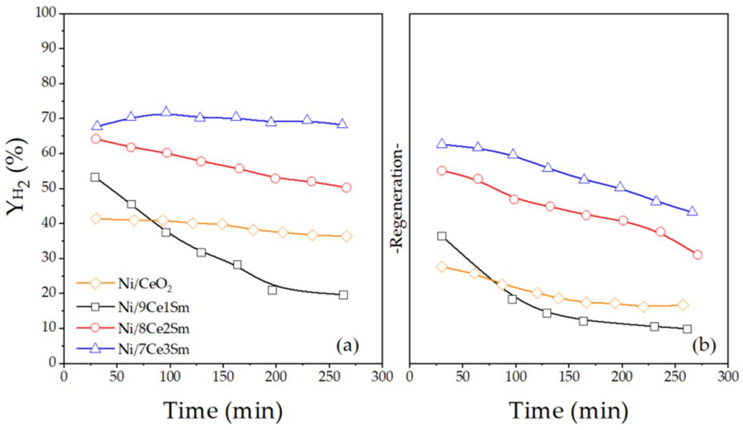
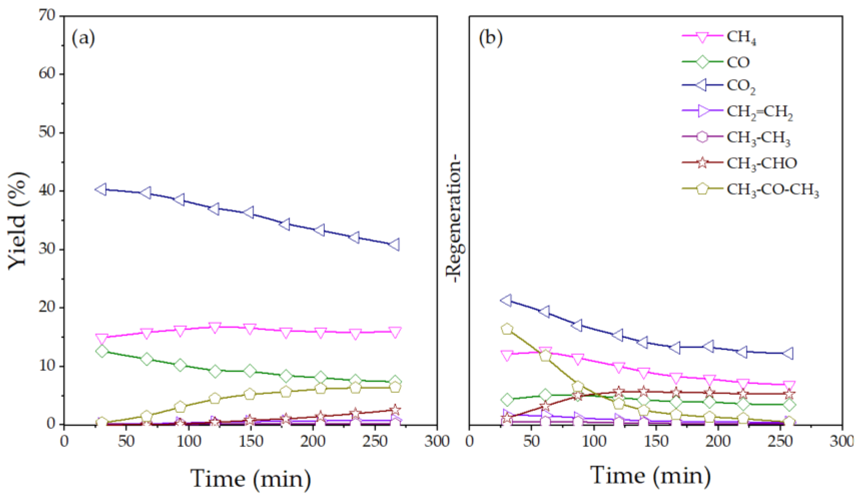
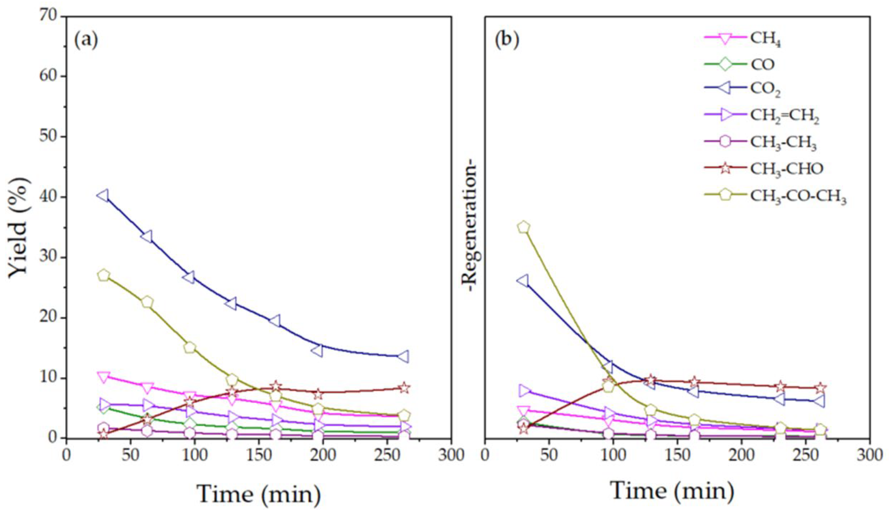
2.2. Catalytic Performance for ESR

Figure 7 shows the evolution of ethanol conversion with run time for each fresh and reactivated catalyst sample, while the evolution of hydrogen yield is depicted in Figure 8.
As observed in Figure 7, the addition of Sm2O3 to the support significantly increases the initial catalytic conversion. Nevertheless, the effect on catalyst stability depends on the proportion of Sm. Fresh samples of Sm-doped catalysts showed initial conversions greater than 90% (Figure 7a); however, as reaction time advanced, two of the catalysts, Ni/9Ce1Sm and Ni/8Ce2Sm, suffered a remarkable decrease in conversion. After 200 min on stream, Ni/9Ce1Sm and Ni/8Ce2Sm catalysts lost 62% and 17% of their initial conversion, respectively. In contrast, the Ni/7Ce3Sm catalyst exhibited stable activity along the reaction time, reaching an average ethanol conversion of 96.7%. The Ni/CeO2 catalyst showed a time evolution similar to Ni/7Ce3Sm, being very stable.
As expected, the hydrogen yield of fresh catalysts, shown in Figure 8a, follows a trend similar to that of ethanol conversion. The initial H2 yield increases with the Sm2O3 content; the Ni/7Ce3Sm catalyst presented a 67% hydrogen yield. This enhancement of catalytic activity is in agreement with the catalysts’ characterization results, as the catalyst with the highest samarium content in the support (30%) exhibits the smallest Ni particle size, and a more homogeneous Ni distribution on the catalyst surface, according to XPS (Table 2) and TEM micrographs. Ni/7Ce3Sm was the most stable catalyst, followed by Ni/CeO2. The higher stability of Ni/7Ce3Sm when compared to Ni/CeO2 can be attributed to the more homogeneous distribution and dispersion of Ni particles and its higher oxygen mobility (Table 2 and Table 3), enhancing oxygen supply to the active centers and preventing coke formation.
The results are in accordance with those of Rodrigues et al. [43], who demonstrated that the Sm-doped Ni/CeO2 catalyst achieved 100% ethanol conversion and 60% H2 selectivity, and catalytic stability during 180 h of reaction.
On the contrary, Ni/9Ce1Sm and Ni/8Ce2Sm catalysts suffered a drop in yield of 60% and 19%, respectively, after 200 min of reaction. The activity loss can be ascribed to a higher Sm concentration on the outer catalyst surface, according to Sm/Ce ratio results (Table 2), modifying the reaction mechanism, as will be discussed below.
Deactivated catalyst samples were reactivated using the activation process described in Section 3. The reactivation showed the same trends in ethanol conversion and hydrogen yield for Ni/9Ce1Sm and Ni/8Ce2Sm catalysts as compared to fresh samples. The Ni/9Ce1Sm and Ni/8Ce2Sm catalysts recovered performance values close to the initial values of the fresh samples (Figure 7b and Figure 8b), but they suffered a slightly stronger deactivation with run time than the fresh ones.
Meanwhile, the reactivated Ni/CeO2 and Ni/7Ce3Sm catalysts exhibited lower initial conversion and hydrogen yield values than the fresh catalysts as well as a faster activity loss. They show drops in ethanol conversion and hydrogen yield of 29–16% and 66–43% for Ni/CeO2 and Ni/7Ce3Sm catalysts, respectively.
Results achieved for the Ni/CeO2 catalyst are in agreement with those reported by Pájaro et al. [22] and Pinton et al. [23], who investigated catalytic ethanol steam reforming by employing the same operating conditions (T = 500 °C, steam/ethanol = 6, and W/F = 0.12 gcat.h/molethanol) and catalyst activation/regeneration method as this research. Pájaro et al. [22] synthesized Ni-Cu/CeO2 catalysts with a (Ni+Cu):Ce = 4:6 ratio through the reverse microemulsion co-precipitation method, demonstrating that the Ni2Cu2Ce6 catalyst recovered the initial activity by the regeneration method. Furthermore, the Ni4Ce6 catalyst reached 100% ethanol conversion and 60% hydrogen yield, and a high stability during more than 16 h of reaction. Nevertheless, regeneration effects were not reported by the authors for the Ni4Ce6 catalyst. Similar results were reported by Pinton et al. [23], who synthesized Ni–Co/CeO2 catalysts with a (Ni+Co)/Ce = 4:6 ratio by the wet impregnation method, finding that the nickel-based catalyst remains stable during the first 6 h after reactivation.
In order to achieve a better understanding of the observed differences in catalytic performance, it is necessary to analyze the distribution of carbonated products and their evolution with reaction time in fresh and regenerated catalysts.
The evolution of yields of carbon-containing products with operating time is reported in Figure 9, Figure 10, Figure 11 and Figure 12 for fresh (a) and reactivated (b) catalyst samples.
All of the catalysts follow the general reaction scheme reported by Pájaro et al. [22] in the catalytic ethanol steam reforming, highlighting the dehydrogenation pathway in the detriment of the dehydration one. According to the results, carbon dioxide (CO2) was the main carbon by-product. The parallel evolution of H2 and CO2 yields and the opposite trend in acetaldehyde yield (that tends to increase as the CO2 yield decreases) indicates that a sequential reaction would be taking place, say, initially, ethanol dehydrogenation into acetaldehyde Equation (3), and then acetaldehyde steam reforming Equation (6) as the predominant reactions. Acetaldehyde decomposition should have a lower contribution due to the small yield of CH4 obtained.
In addition, CO2, CO, and CH4 are the only products obtained when using fresh Ni/7Ce1Sm and Ni/CeO2. Methane (CH4) can come from the thermal acetaldehyde decomposition, Equation (8), or from the methanation of carbon oxides, Equations (11) and (12). In this case, it is understood to be mainly due to methanation, since nickel is known for its hydrogenating properties [29].
On the contrary, significant proportions of acetone and, to a lesser extent, ethylene are obtained for Ni/9Ce1Sm and Ni/8Ce1Sm, with higher yields as the Sm content in the catalyst is increased (Figure 10a). Acetone comes mostly from the acetaldehyde condensation reaction, Equation (9), which requires two molecules of acetaldehyde to be generated. This could also explain the tendency for H2 and acetone yield to decrease with time on stream, as acetaldehyde yield increases, which implies that less acetaldehyde is converted. Ethylene (CH2=CH2) would be generated by ethanol dehydration, Equation (4). Carbon monoxide (CO) is in part generated by acetaldehyde condensation, Equation (9), and consumed in the WGS Equation (10) and methanation reaction, Equations (11) and (12).
Previous studies found that rare earth oxides enhance the adsorption of carbon-containing reactants from the gas phase and increase the rate of diffusion of reactant species across the catalyst surface, because of the increased basicity of the support [42,50,51,52]. This would explain the deactivation behavior of the catalysts. The presence of Sm appears to be beneficial to a certain extent, when Sm is homogeneously distributed into the support, but when the concentration of Sm in the outer surface of catalyst particles is high, as in the case of Ni/9Ce1Sm and Ni/8Ce1Sm, the oligomerization and dehydration of carbonaceous species is promoted, modifying the reaction direction and leading to a strong deactivation of the catalyst. Acetone, acetaldehyde, and ethylene have been reported as precursors of coke formation, suggesting that the strong deactivation observed for these catalysts could be mainly due to this compound [53].
The reactivated catalyst samples (Figure 9b, Figure 10b, Figure 11b and Figure 12b) also yield carbon dioxide (CO2) as the main carbon product. However, the active centers appear to be slightly modified, favoring higher acetone/CO2 ratios.
As with the fresh catalyst, the parallel evolution of H2 and CO2 yields indicates that regeneration treatment did not modify the general scheme and mechanism of the reaction.
In conclusion, a synergistic effect in conversion, H2 yield, and stability is found for the Ni/Ce7Sm3 catalyst. Increasing the Sm2O3 proportion enhanced Ni dispersion and its more homogeneous distribution into the support, which in turn promotes conversion and H2 yield. Moreover, previous studies devoted to other reactions such as reforming or the oxidation of methane and CO2 hydrogenation, reported that basic active centers in the vicinity of the metal particles, provided by Sm2O3 or other rare earths, promoted the adsorption of reactants and favored the surface diffusion of reaction intermediates, thus giving rise to a higher activity per exposed metal atom than for the undoped CeO2-supported catalyst. They concluded that the role of the rare earth oxide was both to enhance the adsorption of reactants from the gas phase and to increase the rate of diffusion of reactant species across the catalyst surface, because of the increased basicity of the support [42,51,52]. However, this effect appears to become unfavorable when Sm2O3 is highly concentrated in the outer catalyst surface, as for Ni/9Ce1Sm and Ni/8Ce1Sm, promoting the oligomerization of carbonaceous species and leading to a strong deactivation of the catalyst. The better stability of Ni/Ce7Sm3 when compared to Ni/CeO2 can be ascribed to the higher oxygen mobility of the support that prevents coke formation and the homogeneous distribution of Ni that prevents metal sintering and coke formation.
The great stability of the catalyst, besides its competitive conversion and hydrogen production values at mild reaction operating conditions, makes the catalyst a firm candidate for scaling up and process simulation towards industrial application. However, considering the complexity of the reaction scheme, a deep study of the evolution of catalytic properties with operating conditions is required to obtain kinetic parameters for modeling the process.

3. Materials and Methods

3.1. Catalyts Preparation

The catalyst supports were prepared using the co-precipitation method. For SDC supports, two solutions, one with 50 g urea dissolved in 100 mL distilled water and the other with a 30 g mixture of ammonium nitrate cerium (IV) ((NH4)2Ce(NO3)6, Sigma-Aldrich, ≥99.99%) and samarium(III) nitrate hexahydrate (Sm(NO3)3·6H2O, Sigma-Aldrich, ≥99.99%) in molar ratios of 9:1, 8:2, or 7:3, in 100 mL distilled water, were used to obtain the supports denoted as 9Ce1Sm, 8Ce2Sm, or 7Ce3Sm, respectively. The two solutions were mixed in a round-bottomed flask stirred and heated with reflux at 100 °C for 5 h. Then, the mixture was cooled down and was continually stirred overnight. The precipitated samples were filtered and washed four times with 200 mL of distilled water, and then dried at 110 °C overnight. The dried samples were calcinated at 500 °C (2 °C/min) for 1 h. A similar procedure was used to prepare a CeO2 support using only ammonium nitrate cerium (IV) for the second solution.
The catalysts (denoted as Ni/9Ce1Sm, Ni/8Ce2Sm, Ni/7Ce3Sm, and Ni/CeO2) were prepared with the molar ratio of Ni/(Ce+Sm) = 4/6 by incipient wetness impregnation, employing nickel nitrate hexahydrate (Ni(NO3)2·6H2O, 99.999%, Sigma-Aldrich) dissolved in an aqueous solution as a Ni precursor. The prepared samples were dried firstly at 100 °C overnight, and then were calcinated at 500 °C (2 °C/min) for 1 h.

3.2. Characterization

N2 adsorption–desorption at −196 °C was employed to analyze the porous structure of the catalysts with Micromeritics equipment (Tristar II 3020). Previously, all of the catalysts were outgassed at 150 °C for at least 4 h. The specific surface areas of catalyst samples were calculated using the BET equation. The Ni particle sizes were analyzed through TEM images obtained from a microscope of JEOL JEM-2100F (Tokyo, Japan), which operated at 200 kV with a resolution of 0.19 nm. The crystalline structure of the catalysts was analyzed via XRD, employing an X’Pert PRO PANalytical diffractometer (Malvern, UK) with a θ:θ configuration. The catalyst samples were scanned by CuKα radiation (λ = 1.5406 Å, 45 kV, 40 mA) with a scan range (2θ) of 4–90° with a step size of 0.04 counting 20 s for each step. The surface composition and oxidation state of catalyst samples were analyzed by XPS, employing a Multitechnique System of Physical Electronics 5700 C (Chanhassen, MN, USA) with a MgKα radiation equal to 1253.6 eV. Broad spectra were obtained along binding energy (BE) up to 1200 eV to analyze the elemental composition each sample. The C1s peak at 284.9 eV was used as an internal standard to correct the changes in BE aroused by sample charging. After smooth Shirley background subtraction, the XPS spectra were deconvoluted using a mixture of Gaussian and Lorentzian functions with variable proportions. The relative atomic composition of elements was related to the area of deconvoluted peaks obtained from related core-level curves using Wagner sensitivity factors [28].

3.3. Catalytic Activity Tests

The activity of the catalysts was evaluated in a continuous flow Microactivity (PID Eng&Tech, Madrid, Spain) which is an automated and computerized laboratory reactor, consisting of a fixed-bed tubular reactor, heating box, six-way diffuser valve, an evaporator, and a condenser or peltier, and coupled with a positive displacement pump. The fixed-bed tubular reactor is made of 316 L stainless steel with a length of 305 mm, an external diameter of 14.5 mm and an internal diameter of 9 mm, inside which the catalyst is deposited on glass wool and silicon carbide (SiC). The temperature inside the reactor is controlled by a K-type thermocouple placed axially in the center of the catalytic bed. The Microactivity is connected online to a gas-chromatograph Varian 3400 CX equipped with a molecular sieve column (13X, Agilent, Madrid, Spain) to separate small molecules (H2, CH4 and CO), and a packed Porapak Q column (Agilent, Madrid, Spain) to separate heavier compounds, using a thermal conductivity detector (TCD) to measure the concentration of ethanol and products.
The liquid feed (water/ethanol) was controlled by a GILSON 307 pump (Madison, WI, USA), which moves the reactants from a container to the evaporator. The vessel is connected to the pump by a three-way valve that allows the pipes to be purged and prevents air from entering the pump. The water/ethanol (99.9%, Scharlau, Barcelona, Spain) mixture with a 6:1 steam/ethanol (S/E) molar ratio is pumped with a flow of 0.05 mL/min to the evaporator, where it evaporates and is carried away by the He stream of 260 mLN/min, to get a feed with molar ratio of He/H2O/ethanol = 79.8:17.3:2.9.
Tests were carried out at 500 °C for around 5 h on stream. In all cases, the same operating conditions were used with a residence time of 0.12 gcat.h.gethanol−1. The catalyst bed was formed by 0.1 g of catalyst particles (0.25–0.42 nm in size) mixed with SiC (0.42–0.59 mm in size), in a catalyst/SiC ratio of 1/3 (v/v) to homogenize the temperature in the catalytic bed. In order to be able to place the catalyst bed in the center of the furnace and at the same level as the thermocouple, a certain amount of SiC of 0.84 mm was set upstream and downstream of the catalytic bed.
Previously to the reaction test, the catalyst samples were activated in situ through an oxidation process under a flow of 100 mlN/min of 10% O2 in He (both gases > 99.999%, supplied by Nippon Gases, Madrid, Spain) at 500 °C for 1 h, raising the temperature with a heating rate of 10 °C/min. Once the activation was complete, the O2 was purged from the reactor for 30 min under a flow of He.
After a first run of ESR, the used catalysts were reactivated by the same oxidation process as used with fresh samples, and tested again in the reaction, with the aim of exploring the possibility of regeneration by this treatment.
Catalytic activity is calculated in terms of ethanol conversion (XEtOH) and product yields (Yi), expressed in % moles.
The yields of carbon compounds (i) are calculated by the following expression:
Y i = F i C i 2 F   E t O H i n × 100 %
where Ci is the number of carbon atoms in the compound (i), Fi is its molar flux (mol/h), and FEtOH-in is the molar flux of ethanol in the feed.
Ethanol conversion (XEtOH) is calculated as the sum of the yields of carbonated products:
X E t O H =   Y i
In addition, taking into account the stoichiometry of the ethanol reforming reaction with steam, the hydrogen yield is calculated by the following expression:
Y E t O H = F H 2 o u t l e t 6 · F E t O H i n l e t × 100 %

4. Conclusions

The effect of the support doping with Sm2O3 of CeO2-supported Ni catalysts on the reforming of ethanol for hydrogen production has been evaluated. Sm2O3 was added to CeO2 in molar ratios of 1:9, 2:8 and 3:7. The performance of the corresponding catalysts in the reaction was compared to that of the Ni/CeO2 catalyst. The Sm2O3 addition promotes ethanol conversion and H2 yield. Increasing the Sm content leads to higher ethanol conversion and hydrogen yield. In addition, it also increases the basicity that promotes the adsorption of reactants and favors the surface diffusion of reaction intermediates, which may contribute to promote the activity of active centers.
However, the stability of the catalysts is not always promoted by Sm2O3 addition, as it highly depends on the Sm2O3 content. The deactivation of the catalysts is enhanced by the presence of high concentrations of Sm in the outer surface of the catalyst particles, which appears to promote condensation reactions and coke formation since the adsorption of carbonaceous reactants is favored. As a consequence, Ni/8Ce2Sm and Ni/9Ce1Sm show a stronger deactivation than the Ni/7Ce3Sm and Ni/CeO2 catalysts. The higher stability of Ni/7Ce3Sm compared to Ni/CeO2 can be attributed to a better dispersion of Ni and a better distribution into the support, in addition to a higher oxygen mobility of the support that prevents deactivation.
The catalyst with the higher Sm2O3 content (Ni/7Ce3Sm) presents unique physico-chemical properties (homogeneous Ni and Sm distribution, high Ni dispersion, and high oxygen mobility), conferring to the catalyst outstanding behavior in ethanol reforming in terms of ethanol conversion, H2 yield, and catalytic stability.

Supplementary Materials

The following supporting information can be downloaded at: https://www.mdpi.com/article/10.3390/catal15020131/s1, Figure S1: Nitrogen adsorption-desorption isotherms of catalysts: (a) Ni/9Ce1Sm; (b) Ni/8Ce2Sm and (c) Ni/7Ce3Sm.

Author Contributions

Conceptualization, V.C.C. and L.M.G.-S.; methodology, V.C.C., L.M.G.-S., C.A.C. and S.L.; investigation, C.A.C. and S.L.; writing—original draft preparation, C.A.C., S.L. and L.M.G.-S.; writing—review and editing, V.C.C. and L.M.G.-S.; supervision, V.C.C. and L.M.G.-S.; project administration, V.C.C. and L.M.G.-S.; funding acquisition, V.C.C. and L.M.G.-S. All authors have read and agreed to the published version of the manuscript.

Funding

This research was funded by FEDER/Ministerio de Ciencia, Innovación y Universidades—Agencia Estatal de Investigación (CTM2017-85498-R) and Ministerio de Ciencia, Innovación y Universidades (projects RTI2018-101604-B-I00 and PID2021-128915NB-I00).

Data Availability Statement

Data will be made available on request.

Acknowledgments

The authors acknowledge FEDER and Ministerio de Ciencia, Innovación y Universidades—Agencia Estatal de Investigación for their funding. Sichen Liu acknowledges Ministerio de Ciencia e Innovación for his research grant (PRE2018-084424).

Conflicts of Interest

The authors declare no conflicts of interest. The funders had no role in the design of the study; in the collection, analyses, or interpretation of data; in the writing of the manuscript; or in the decision to publish the results.

References

  1. Manoharan, Y.; Hosseini, S.E.; Butler, B.; Alzhahrani, H.; Senior, B.T.F.; Ashuri, T.; Krohn, J. Hydrogen Fuel Cell Vehicles; Current Status and Future Prospect. Appl. Sci. 2019, 9, 2296. [Google Scholar] [CrossRef]
  2. Xu, X.; Zhou, Q.; Yu, D. The Future of Hydrogen Energy: Bio-Hydrogen Production Technology. Int. J. Hydrogen Energy 2022, 47, 33677–33698. [Google Scholar] [CrossRef]
  3. Altaf, C.T.; Colak, T.O.; Karagoz, E.; Kurt, M.; Sankir, N.D.; Sankir, M. A Review of the Recent Advances in Composite Membranes for Hydrogen Generation Technologies. ACS Omega 2024, 9, 23138–23154. [Google Scholar] [CrossRef] [PubMed]
  4. Arcos, J.M.M.; Santos, D.M.F. The Hydrogen Color Spectrum: Techno-Economic Analysis of the Available Technologies for Hydrogen Production. Gases 2023, 3, 25–46. [Google Scholar] [CrossRef]
  5. Lindström, B.; Pettersson, L.J. Deactivation of Copper-Based Catalysts for Fuel Cell Applications. Catal. Lett. 2001, 74, 27–30. [Google Scholar] [CrossRef]
  6. Hu, G.; Chen, C.; Lu, H.T.; Wu, Y.; Liu, C.; Tao, L.; Men, Y.; He, G.; Li, K.G. A Review of Technical Advances, Barriers, and Solutions in the Power to Hydrogen (P2H) Roadmap. Engineering 2020, 6, 1364–1380. [Google Scholar] [CrossRef]
  7. Parkhey, P. Biomethanol: Possibilities towards a Bio-Based Economy. Biomass Convers. Biorefin. 2022, 12, 1877–1887. [Google Scholar] [CrossRef]
  8. Hasegawa, F.; Yokoyama, S.; Imou, K. Methanol or Ethanol Produced from Woody Biomass: Which Is More Advantageous? Bioresour. Technol. 2010, 101, S109–S111. [Google Scholar] [CrossRef]
  9. Molino, A.; Larocca, V.; Chianese, S.; Musmarra, D. Biofuels Production by Biomass Gasification: A Review. Energies 2018, 11, 811. [Google Scholar] [CrossRef]
  10. Rosha, P.; Ali, F.M.; Ibrahim, H. Recent Advances in Hydrogen Production through Catalytic Steam Reforming of Ethanol: Advances in Catalytic Design. Can. J. Chem. Eng. 2023, 101, 5498–5518. [Google Scholar] [CrossRef]
  11. Boudadi, K.; Bellifa, A.; Márquez-Álvarez, C.; Cortés Corberán, V. Nickel Catalysts Promoted with Lanthanum for Ethanol Steam Reforming: Influence of Support and Treatment on Activity. Appl. Catal. A Gen. 2021, 619, 118141. [Google Scholar] [CrossRef]
  12. Palma, V.; Castaldo, F.; Ciambelli, P.; Iaquaniello, G.; Palma, V.; Castaldo, F.; Ciambelli, P.; Iaquaniello, G. Sustainable Hydrogen Production by Catalytic Bio-Ethanol Steam Reforming. In Greenhouse Gases—Capturing, Utilization and Reduction; IntechOpen: London, UK, 2012. [Google Scholar] [CrossRef]
  13. Mattos, L.V.; Jacobs, G.; Davis, B.H.; Noronha, F.B. Production of Hydrogen from Ethanol: Review of Reaction Mechanism and Catalyst Deactivation. Chem. Rev. 2012, 112, 4094–4123. [Google Scholar] [CrossRef]
  14. Lin, J.; Chen, L.; Choong, C.K.S.; Zhong, Z.; Huang, L. Molecular Catalysis for the Steam Reforming of Ethanol. Sci. China Chem. 2015, 58, 60–78. [Google Scholar] [CrossRef]
  15. Hou, T.; Yu, B.; Zhang, S.; Xu, T.; Wang, D.; Cai, W. Hydrogen Production from Ethanol Steam Reforming over Rh/CeO2 Catalyst. Catal. Commun. 2015, 58, 137–140. [Google Scholar] [CrossRef]
  16. Cai, W.; Wang, F.; Daniel, C.; Van Veen, A.C.; Schuurman, Y.; Descorme, C.; Provendier, H.; Shen, W.; Mirodatos, C. Oxidative Steam Reforming of Ethanol over Ir/CeO2 Catalysts: A Structure Sensitivity Analysis. J. Catal. 2012, 286, 137–152. [Google Scholar] [CrossRef]
  17. Palma, V.; Castaldo, F.; Ciambelli, P.; Iaquaniello, G. CeO2-Supported Pt/Ni Catalyst for the Renewable and Clean H2 Production via Ethanol Steam Reforming. Appl. Catal. B 2014, 145, 73–84. [Google Scholar] [CrossRef]
  18. Ramos, I.A.C.; Montini, T.; Lorenzut, B.; Troiani, H.; Gennari, F.C.; Graziani, M.; Fornasiero, P. Hydrogen Production from Ethanol Steam Reforming on M/CeO2/YSZ (M = Ru, Pd, Ag) Nanocomposites. Catal. Today 2012, 180, 96–104. [Google Scholar] [CrossRef]
  19. Vaidya, P.D.; Rodrigues, A.E. Kinetics of Steam Reforming of Ethanol over a Ru/Al2O3 Catalyst. Ind. Eng. Chem. Res. 2006, 45, 6614–6618. [Google Scholar] [CrossRef]
  20. Sharma, Y.C.; Kumar, A.; Prasad, R.; Upadhyay, S.N. Ethanol Steam Reforming for Hydrogen Production: Latest and Effective Catalyst Modification Strategies to Minimize Carbonaceous Deactivation. Renew. Sustain. Energy Rev. 2017, 74, 89–103. [Google Scholar] [CrossRef]
  21. Mathure, P.V.; Ganguly, S.; Patwardhan, A.V.; Saha, R.K. Steam Reforming of Ethanol Using a Commercial Nickel-Based Catalyst. Ind. Eng. Chem. Res. 2007, 46, 8471–8479. [Google Scholar] [CrossRef]
  22. Pájaro, K.C.; Cortés Corberán, V.; Martínez-Arias, A. Influence of the Interaction of Nickel and Copper with Ceria on Ethanol Steam Reforming over Ni-Cu-CeO2 Catalysts. Catalysts 2024, 14, 605. [Google Scholar] [CrossRef]
  23. Pinton, N.; Vidal, M.V.; Signoretto, M.; Martínez-Arias, A.; Cortés Corberán, V. Ethanol Steam Reforming on Nanostructured Catalysts of Ni, Co and CeO2: Influence of Synthesis Method on Activity, Deactivation and Regenerability. Catal. Today 2017, 296, 135–143. [Google Scholar] [CrossRef]
  24. Cao, A.N.T.; Ng, K.H.; Ahmed, S.F.; Nguyen, H.T.; Kumar, P.S.; Tan, H.T.; Rajamohan, N.; Yusuf, M.; Show, P.L.; Balakrishnan, A.; et al. Hydrogen Generation by Heterogeneous Catalytic Steam Reforming of Short-Chain Alcohols: A Review. Environ. Chem. Lett. 2023, 22, 561–583. [Google Scholar] [CrossRef]
  25. Feng, X.; Zhao, Y.; Zhao, Y.; Wang, H.; Liu, H.; Zhang, Q. A Mini Review on Recent Progress of Steam Reforming of Ethanol. RSC Adv. 2023, 13, 23991–24002. [Google Scholar] [CrossRef] [PubMed]
  26. Wang, H.; Zhu, H.; Zhang, Y.; Pu, J. Highly Active Ni/CeO2 for the Steam Reforming of Acetic Acid Using CTAB as Surfactant Template. Int. J. Hydrogen Energy 2022, 47, 27493–27507. [Google Scholar] [CrossRef]
  27. Remiro, A.; Arandia, A.; Oar-Arteta, L.; Bilbao, J.; Gayubo, A.G. Stability of a Rh/CeO2-ZrO2 Catalyst in the Oxidative Steam Reforming of Raw Bio-Oil. Energy Fuels 2018, 32, 3588–3598. [Google Scholar] [CrossRef]
  28. Yadav, A.K.; Vaidya, P.D. Hydrogen Production From Steam Butanol Reforming Over Cobalt Catalyst Supported On Ceria. Catal. Green. Chem. Eng. 2023, 6, 1–14. [Google Scholar] [CrossRef]
  29. Xu, W.; Liu, Z.; Johnston-Peck, A.C.; Senanayake, S.D.; Zhou, G.; Stacchiola, D.; Stach, E.A.; Rodriguez, J.A. Steam Reforming of Ethanol on Ni/CeO2: Reaction Pathway and Interaction between Ni and the CeO2 Support. ACS Catal. 2013, 3, 975–984. [Google Scholar] [CrossRef]
  30. Min, P.; Zhang, S.; Xu, Y.; Li, R. Enhanced Oxygen Storage Capacity of CeO2 with Doping-Induced Unstable Crystal Structure. Appl. Surf. Sci. 2018, 448, 435–443. [Google Scholar] [CrossRef]
  31. Ogo, S.; Sekine, Y. Recent Progress in Ethanol Steam Reforming Using Non-Noble Transition Metal Catalysts: A Review. Fuel Process. Technol. 2020, 199, 106238. [Google Scholar] [CrossRef]
  32. Kosinski, M.R.; Baker, R.T. Preparation and Property–Performance Relationships in Samarium-Doped Ceria Nanopowders for Solid Oxide Fuel Cell Electrolytes. J. Power Sources 2011, 196, 2498–2512. [Google Scholar] [CrossRef]
  33. Go, D.; Kim, T.; Li, H.; Garcia, T.J.; Yang, B.C.; Gür, T.M.; Lee, M.H.; An, J. PEALD Ru-Decorated Ni-SDC Cermet Anode for Utilizing Methane Fuel in Low-Temperature SOFCs. Surf. Interfaces 2024, 44, 103657. [Google Scholar] [CrossRef]
  34. Tepamatr, P.; Laosiripojana, N.; Sesuk, T.; Charojrochkul, S. Effect of Samarium and Praseodymium Addition on Water Gas Shift Performance of Co/CeO2 Catalysts. J. Rare Earths 2020, 38, 1201–1206. [Google Scholar] [CrossRef]
  35. AlKhoori, A.A.; Polychronopoulou, K.; Belabbes, A.; Jaoude, M.A.; Vega, L.F.; Sebastian, V.; Hinder, S.; Baker, M.A.; Zedan, A.F. Cu, Sm Co-Doping Effect on the CO Oxidation Activity of CeO2. A Combined Experimental and Density Functional Study. Appl. Surf. Sci. 2020, 521, 146305. [Google Scholar] [CrossRef]
  36. Huang, T.J.; Jhao, S.Y. Ni-Cu/Samaria-Doped Ceria Catalysts for Steam Reforming of Methane in the Presence of Carbon Dioxide. Appl. Catal. A Gen. 2006, 302, 325–332. [Google Scholar] [CrossRef]
  37. Chien, A.C.; Ye, N.J.; Huang, C.W.; Tseng, I.H. Studies of Nickel/Samarium-Doped Ceria for Catalytic Partial Oxidation of Methane and Effect of Oxygen Vacancy. Catalysts 2021, 11, 731. [Google Scholar] [CrossRef]
  38. Wang, J.B.; Li, C.H.; Huang, T.J. Study of Partial Oxidative Steam Reforming of Methanol over Cu-ZnO/Samaria-Doped Ceria Catalyst. Catal. Lett. 2005, 103, 239–247. [Google Scholar] [CrossRef]
  39. Laobuthee, A.; Veranitisagul, C.; Wattanathana, W.; Koonsaeng, N.; Laosiripojana, N. Activity of Fe Supported by Ce1−xSmxO2−δ Derived from Metal Complex Decomposition toward the Steam Reforming of Toluene as Biomass Tar Model Compound. Renew. Energy 2015, 74, 133–138. [Google Scholar] [CrossRef]
  40. Kosinski, M.R.; Vizcaíno, A.J.; Gómez-Sainero, L.M.; Carrero, A.; Baker, R.T. Methanol Reforming by Nanostructured Pd/Sm-Doped Ceria Catalysts. Appl. Catal. B 2021, 286, 119935. [Google Scholar] [CrossRef]
  41. Gómez-Sainero, L.M.; Baker, R.T.; Metcalfe, I.S.; Sahibzada, M.; Concepción, P.; López-Nieto, J.M. Investigation of Sm2O3–CeO2-Supported Palladium Catalysts for the Reforming of Methanol: The Role of the Support. Appl. Catal. A Gen. 2005, 294, 177–187. [Google Scholar] [CrossRef]
  42. Gómez-Sainero, L.M.; Baker, R.T.; Vizcaíno, A.J.; Francis, S.M.; Calles, J.A.; Metcalfe, I.S.; Rodriguez, J.J. Steam Reforming of Methanol with Sm 2O 3-CeO 2-Supported Palladium Catalysts: Influence of the Thermal Treatments of Catalyst and Support. Ind. Eng. Chem. Res. 2009, 48, 8364–8372. [Google Scholar] [CrossRef]
  43. Rodrigues, T.S.; de Moura, A.B.L.; e Silva, F.A.; Candido, E.G.; da Silva, A.G.M.; de Oliveira, D.C.; Quiroz, J.; Camargo, P.H.C.; Bergamaschi, V.S.; Ferreira, J.C.; et al. Ni Supported Ce0.9Sm0.1O2−δ Nanowires: An Efficient Catalyst for Ethanol Steam Reforming for Hydrogen Production. Fuel 2019, 237, 1244–1253. [Google Scholar] [CrossRef]
  44. Rangaswamy, A.; Sudarsanam, P.; Reddy, B.M. Rare Earth Metal Doped CeO2-Based Catalytic Materials for Diesel Soot Oxidation at Lower Temperatures. J. Rare Earths 2015, 33, 1162–1169. [Google Scholar] [CrossRef]
  45. NIST X-Ray Photoelectron Spectroscopy Database. Available online: https://srdata.nist.gov/xps/EnergyTypeElement (accessed on 15 January 2025).
  46. Golubina, E.V.; Rostovshchikova, T.N.; Lokteva, E.S.; Maslakov, K.I.; Nikolaev, S.A.; Egorova, T.B.; Gurevich, S.A.; Kozhevin, V.M.; Yavsin, D.A.; Yermakov, A.Y. Chlorobenzene Hydrodechlorination on Bimetallic Catalysts Prepared by Laser Electrodispersion of NiPd Alloy. Pure Appl. Chem. 2018, 90, 1685–1701. [Google Scholar] [CrossRef]
  47. Zhang, C.; Lin, J. Visible-Light Induced Oxo-Bridged ZrIV−O−CeIII Redox Centre in Tetragonal ZrO2–CeO2 Solid Solution for Degradation of Organic Pollutants. Phys. Chem. Chem. Phys. 2011, 13, 3896–3905. [Google Scholar] [CrossRef]
  48. Cardenas, L.; Molinet-Chinaglia, C.; Loridant, S. Unraveling Ce3+ Detection at the Surface of Ceria Nanopowders by UPS Analysis. Phy. Chem. Chem. Phy. 2022, 24, 22815–22822. [Google Scholar] [CrossRef]
  49. Zhong, B.; Liang, Z.; Huang, J.; Ye, Y.; Liu, Y.; Wang, T. Effect of CeO2 Morphology in Catalytic Performance via Methanol Oxidative Steam Reforming for Hydrogen Production. Cite This Ind. Eng. Chem. Res. 2024, 63, 6533. [Google Scholar] [CrossRef]
  50. Yang, C.; Bebensee, F.; Chen, J.; Yu, X.; Nefedov, A.; Wöll, C. Carbon Dioxide Adsorption on CeO2(110): An XPS and NEXAFS Study. ChemPhysChem 2017, 18, 1874–1880. [Google Scholar] [CrossRef]
  51. Panayotov, D.; Zdravkova, V.; Lagunov, O.; Andonova, S.; Spassova, I.; Nihtianova, D.; Atanasova, G.; Drenchev, N.; Ivanova, E.; Mihaylov, M.; et al. Capturing CO2 by Ceria and Ceria–Zirconia Nanomaterials of Different Origin. Phys. Chem. Chem. Phys. 2023, 25, 17154–17175. [Google Scholar] [CrossRef]
  52. Phung, T.K.; Pham, T.L.M.; Nguyen, A.N.T.; Vu, K.B.; Giang, H.N.; Nguyen, T.A.; Huynh, T.C.; Pham, H.D. Effect of Supports and Promoters on the Performance of Ni-Based Catalysts in Ethanol Steam Reforming. Chem. Eng. Technol. 2020, 43, 672–688. [Google Scholar] [CrossRef]
  53. Vicente, J.; Ereña, J.; Montero, C.; Azkoiti, M.J.; Bilbao, J.; Gayubo, A.G. Reaction Pathway for Ethanol Steam Reforming on a Ni/SiO2 Catalyst Including Coke Formation. Int. J. Hydrogen Energy 2014, 39, 18820–18834. [Google Scholar] [CrossRef]
Figure 1. Ni2p XPS spectra of (a) Ni/CeO2, (b) Ni/9Ce1Sm, (c) Ni/8Ce2Sm, and (d) Ni/7Ce3Sm catalysts.
Catalysts 15 00131 g001
Figure 2. Ce3d XPS spectra of (a) Ni/CeO2, (b) Ni/9Ce1Sm, (c) Ni/8Ce2Sm, and (d) Ni/7Ce3Sm catalysts.
Catalysts 15 00131 g002
Figure 3. Sm3d XPS spectra of (a) Ni/9Ce1Sm, (b) Ni/8Ce2Sm, and (c) Ni/7Ce3Sm catalysts.
Catalysts 15 00131 g003
Figure 4. O1s XPS spectra of (a) Ni/CeO2, (b) Ni/9Ce1Sm, (c) Ni/8Ce2Sm, and (d) Ni/7Ce3Sm catalysts.
Catalysts 15 00131 g004
Figure 5. X-ray diffractograms of support and catalysts. Symbols: ■: CeO2, *: NiO.
Catalysts 15 00131 g005
Figure 6. Representative TEM micrographs of the as-prepared catalysts (A) Ni/9Ce1Sm, (B) Ni/8Ce2Sm, and (C) Ni/7Ce3Sm.
Catalysts 15 00131 g006
Figure 7. Ethanol conversion on ESR for (a) fresh and (b) reactivated catalysts. Reaction conditions: T = 500 °C, P = 1 atm, S/E ratio = 6, and τ = 0.12 gcat.h.gethanol−1.
Catalysts 15 00131 g007
Figure 8. Hydrogen yield on ESR for (a) fresh and (b) reactivated catalysts. Reaction conditions: T = 500 °C, P = 1 atm, S/E ratio = 6, and τ = 0.12 gcat.h.gethanol−1.
Catalysts 15 00131 g008
Figure 9. Evolution of carbon-containing product yields in ESR on (a) fresh and (b) reactivated Ni/CeO2 catalysts. Reaction conditions: T = 500 °C, P = 1 atm, S/E ratio = 6, and τ = 0.12 gcat.h.gethanol−1.
Catalysts 15 00131 g009
Figure 10. Evolution of carbon-containing product yields in ESR on (a) fresh and (b) reactivated Ni/9Ce1Sm catalysts. Reaction conditions: T = 500 °C, P = 1 atm, S/E ratio = 6, and τ = 0.12 gcat.h.gethanol−1.
Catalysts 15 00131 g010
Figure 11. Evolution of carbon-containing product yields in ESR on (a) fresh and (b) reactivated Ni/8Ce2Sm catalysts. Reaction conditions: T = 500 °C, P = 1 atm, S/E ratio = 6, and τ = 0.12 gcat.h.gethanol−1.
Catalysts 15 00131 g011
Figure 12. Evolution of carbon-containing products yields in ESR for (a) fresh and (b) reactivated Ni/7Ce3Sm catalysts. Reaction conditions: T = 500 °C, P = 1 atm, S/E ratio = 6, and τ = 0.12 gcat.h.gethanol−1.
Catalysts 15 00131 g012
Table 1. Textural properties of supports and catalysts.
SampleBET Surface Area (m2/g)Pore Volume (cm3/g)Average Pore
Diameter (nm)
9Ce1Sm1800.132.8
8Ce2Sm1540.164.1
7Ce3Sm1620.215.1
Ni/9Ce1Sm1220.113.5
Ni/8Ce2Sm970.114.5
Ni/7Ce3Sm940.156.2
Table 2. Bulk and surface atomic ratios of the catalysts and Oads/(Olatt + Oads) ratio.
CatalystsNi/Ce+SmSm/CeOads/(Olatt + Oads)
NominalXPSNominalXPS
Ni/CeO20.6714.07--31.7%
Ni/9Ce1Sm0.679.730.220.4934.2%
Ni/8Ce2Sm0.674.960.501.0341.9%
Ni/7Ce3Sm0.672.110.860.5059.0%
Table 3. CeO2 crystal size of supports and catalysts.
SampleDCe2O aDNiO b
(nm)(nm)
CeO27.3-
9Ce1Sm6.6-
8Ce2Sm5.9-
7Ce3Sm5.4-
Ni/CeO26.947.9
Ni/9Ce1Sm6.023.6
Ni/8Ce2Sm5.318.8
Ni/7Ce3Sm4.913.6
a Calculated from the (111) reflection plane of the CeO2 pattern in XRD. b Calculated from the (200) reflection plane of the NiO pattern in XRD.
Disclaimer/Publisher’s Note: The statements, opinions and data contained in all publications are solely those of the individual author(s) and contributor(s) and not of MDPI and/or the editor(s). MDPI and/or the editor(s) disclaim responsibility for any injury to people or property resulting from any ideas, methods, instructions or products referred to in the content.

