Abstract
In this paper, the cladding of pure aluminum and a low-carbon steel alloy was performed through friction stir processing with minimal intermetallic compound formation. A 3 mm thick aluminum plate was clamped on top of a steel plate. A thick, pure copper plate was used as a backing plate. The tool pin length was adjusted to be the same as the upper plate’s thickness (3 mm) and longer than 3.2 mm. The effect of the tool pin length and the rotation speed (500–1500 rpm) on the cladding’s quality, microstructure, and the mechanical properties of the steel/aluminum interface were investigated using optical and scanning electron microscopy, a hardness test, and a peel test. The results showed that the bonding of pure aluminum and a low-carbon steel alloy can be successfully performed at a more than 500 rpm rotation speed. At a tool pin length of 3 mm and a rotation speed of 1000 rpm, sound and free-intermetallic compound–cladding interfaces were formed, while some Fel2Al5 intermetallics were formed when the rotation speed was increased to 1500 rpm. The pure copper backing plate has an essential role in eliminating or reducing the formation of intermetallic compounds in the cladding interface. When the tool pin length was increased to 3.2 mm, more steel fragments were found on the aluminum side. Moreover, with a higher rotation speed and longer tool pin length, more Fe2Al5 intermetallics were formed at the interface. Increasing the rotation speed and the pin tool length contributed to the enhancement of interface bonding. Meanwhile, the maximum tensile shear load was obtained at a rotation speed of 1500 rpm and a tool pin length of 3.2 mm. In addition, the hardness values of the interface were higher than the aluminum base metal for all the investigated samples. Decreasing the rotation speed and increasing the tool pin length can significantly increase hardness measurements. The average hardness increases from 42 HV of the pure aluminum to 143 HV at a rotation speed and a tool pin length of 1500 rpm and 3.2, respectively.
1. Introduction
Steel and aluminum alloys have different chemical, physical, and mechanical properties. Aluminum alloys have good thermal and electrical conductivity and good corrosion resistance in addition to their low density. At the same time, aluminum has no ability to resist severe wear or erosion. In addition, its strength is relatively limited [1]. On the other hand, steels have high strength, rigidity, and wear resistance. However, their thermal and electrical conductivities, in addition to their corrosion resistance, are weak [2]. It is desirable or sometimes necessary to combine in one material the properties of both aluminum and steel for some specific applications. On one side, aluminum will withstand the attack of corrosive media, while the steel on the other side will provide the necessary strength and sometimes erosion and wear resistance. In other applications, aluminum will provide good electrical and thermal properties [3]. The establishment of aluminum/steel clad plates exhibits the best features of the two metals, namely, the good mechanical properties of steel and the thermal and electrical properties and corrosion resistance of aluminum compared with a single metal. Such kinds of cladded metals have wide applications represented in many fields, such as the automotive industry, shipbuilding, the aerospace industry, the study/manufacture of heat exchangers, aviation, railway, transfer pipes, kitchen utensils, chemical industries, and atomic energy [4]. For example, in the automotive industry, dissimilar aluminum/steel can be used in the assembly of many parts (pillars, bonnets, door panels, and trunk lids). Their use will reduce the vehicle’s weight and, consequently, its consumption of fuel [5,6].
The methods of dissimilar metals cladding can be divided into liquid state processes such as welding and laser and thermal sprays and solid-state processes such as extrusion, explosive cladding, magnetic pulse welding, and roll bonding [7,8]. For liquid state processes, where a high temperature is often required, many difficulties are related to the large differences in melting temperatures and thermal properties [9]. Moreover, the formation of thick, brittle intermetallics in the interface is considered one of the serious problems and leads to the deterioration of the bonding strength of the cladded metals [10]. According to Fe–Al phase diagram [11], six main intermetallic compounds, including FeAl2, Fe2Al5, FeAl3, Fe3Al, and FeAl, can be easily formed. The iron-rich intermetallics Fe3Al and FeAl are relatively safe, but at higher temperatures they become unstable and transform into other brittle intermetallics.
On the other hand, the aluminum-rich intermetallics, namely, Fe2Al5, FeAl2, and FeAl3, are highly brittle phases and will deteriorate the bonding strength of cladded areas if they are formed in the interface. Unfortunately, these brittle phases are expected to be formed due to the low solubility of iron in an aluminum matrix and the higher diffusion and mobility of aluminum atoms into iron grains [12]. In addition, the thermodynamic data indicate that the formation of brittle aluminum-rich intermetallics is preferable to iron-rich ones. The Gibbs energy or enthalpies of formation for the reactions that formed the Al-rich intermetallics are more negative for large scales, which indicates the higher driving force for the precipitation of these intermetallic phases [13,14,15]. The larger scale is for the most brittle intermetallic (Fe2Al5), indicating that the chances of the formation of this intermetallic phase are higher. Thus, Fe2Al5 is predicted to form first between Al and Fe particles [16]. On the other hand, the scale of Gibbs energy for the iron-rich intermetallics is very narrow, and it increases with an increasing temperature, indicating the difficulty of their formation [15].
To overcome these serious problems, a solid-state cladding process must be used, in which the cladding is applied below the melting point of both clad metals. Unfortunately, most of the solid-state methods are expensive, and it is difficult to control the plastic deformation during a bonding operation, in addition to inducing a large number of internal stresses [17]. Cold rolling is considered one of the most famous and economical solid-state techniques that is used as a cladding process [18]. However, the interface adhesion of the cold rolling is relatively weak. In addition, the cold-rolling process usually needs heat treatment processes such as annealing to remove the strain hardening caused by cold rolling. Unfortunately, the annealing heat treatment temperature is very close to the temperature of intermetallics’ formation [19,20]. In particular, a considerable number of works on cold rolling for preparing clad metals have been published. Grydin et al. [20] experimentally produced steel/aluminum clad sheets by vertical twin roll-casting. An austenitic steel strip was used as the clad strip fed through the gap between the roll and the nozzle. A commercially pure aluminum melt was poured into the nozzle to form the base strip. A 3 μm thick diffusional layer was formed at the interface, and intermetallic phases such as Fe2Al5, Fe4Al13, and FeAl were found at the bonding zone. Chen et al. [21] succeeded in producing a stainless steel/aluminum clad sheet by horizontal twin-roll casting. The interface morphology, element distribution, and bonding strength of the clad sheets after different annealing and cold-rolling processes were investigated. An annealing treatment at 510 °C improved the bonding quality of the interface. When the annealing temperature was increased to 540 °C, the diffusional layer became almost three times the original thickness, which weakened the bonding strength. Akramifard et al. [22] used cold roll bonding to bond aluminum and 304L stainless steel. The results revealed that layers of intermetallics composed mainly of Fe4Al13, FeC, and Al8SiC7 were formed and deteriorated the bond quality. Another study by Wu et al. [23] used cold roll bonding to bond nitrided steel sheets with a 4A60 aluminum alloy. A brittle and hardened layer of Fe3N intermetallics with a thickness of 10 μm was formed at the interface. Moreover, many cracks and pores were found at the interface.
Explosive welding is also used in many applications where high temperatures are locally reached in quite a short time, restricting the formation of intermetallics between the bonded dissimilar metals. It is the appropriate process for large cladding areas [24,25]. The impact forces of explosives create a compression force that is utilized to cause local plastic deformation, which causes the bonding of the overlapping dissimilar metal sheets. Explosive welding by the expansion of the inner tubular component was analyzed by Sun et al. [26], and the bonding characteristics of the Fe/Al clad tube were investigated. The results showed that the clad tubes have a higher shear strength than that of pure aluminum and can bear both axial and radial deformations.
In recent years, a new solid-state process, namely, friction stir processing (FSP), has been developed [27]. FSP is a green, solid-state technology with significant advantages even over other solid-state methods. So far, FSP can be used as a surface modification technique, for grain refinement, for composite formation, and for welding metals. A high-speed-rotating shouldered tool is inserted deeply into the metal until the shoulder touches the surface. Enough heat will be generated by the friction and the severe plastic deformation around the tool, which softens the material, thereby yielding a refined and sound microstructure at a specific location [28]. The solid-state nature of the FSP process avoids the deleterious phase transformation defects that occur by relying on thermo-mechanical-processing methods that maintain a temperature below that of the melting temperature of the base material, as presented by Mishra et al. [29]. Moreover, FSP has become an alternative method used to improve microstructural features, such as grain refinement and particle dispersion, and to improve performance in castings and wrought products. Ibrahim et al. [30] used FSP to clad ASTM A516-70 steel with a 5052 Al alloy. The authors investigated the effect of FSP process parameters on the microstructural and mechanical properties of the cladded zones. They tried to optimize the process parameters, rotational speed, and feed rate to achieve good mechanical bonding without defects. The authors reported that some intermetallic compounds (Fe4Al13, Fe2Al5, and FeAl) were detected in all the tested samples, which negatively affected the bonding quality. Zhang et al. [31] developed a novel friction stir brazing (FSB) process using a pinless tool together with preplaced braze/solder between the cladded metals. The joining process was achieved by metallurgical reaction with the aid of the mechanical effect of a large rotating shoulder, where it acts as a heating and forcing tool. The authors used Zn foil as filler metal to remove the oxide films on the Al’s surface by expulsing them together with the liquid phase, formed by the eutectic reaction between the Zn filler with the Al base metal, and then to extend the bonding area.
The formation of intermetallic compounds at the interface between Al and steel and their numbers depend mainly on the temperature and time employed. In this work, we aim to clad aluminum with steel through FSP and minimize intermetallic formation to its lowest level. It is well established that the FSP parameters play a vital role in the joining quality and in the microstructural evolution in the processed zone and at the interface [32,33]. The main FSP parameters are the tool’s rotation speed, the feed rate, and the tool’s dimensions, which control the amount of heat generated and the degree of plastic deformation under the tool shoulder and around the tool pin [34,35,36]. For that reason, we will study the effect of two parameters, rotation speed and tool pin length, on the microstructure of the stirred zone. We chose two tool pin lengths. The first one was just equal to the thickness of the upper part (3 mm). That means the pin will not penetrate the lower steel component, which only touches the bottom of the pin. This will reduce the amount of steel that will be mixed inside the aluminum part. The second pin length is 3.2 mm, which means that it will penetrate 0.2 mm inside the steel plate. In addition, a high conductive copper plate was used as a baking plate to accelerate the cooling rate. Complete metallurgical and mechanical investigations were carried out.
2. Experimental Procedures
Plates of commercial low-carbon steel and commercial pure aluminum, both 3 mm thick, were cut to nominal dimensions of 250 mm in length and 100 mm in width to be used as base metals. The aluminum plates were fixed rigidly on the top surface of the steel plates. Prior to the application of the Friction stir processing technique, the workpiece (the steel plate covered by the aluminum plate) was firmly clamped to the machine working table together with the backing plate. The baking plate, which was 15 mm thick, was made from pure copper to accelerate heat dissipation. FSP was performed in this study using a vertical type milling machine with a power capacity of 9 kW. A ready-to-use tool was fabricated from tungsten carbide powder through the powder metallurgy technique. Tool dimensions consisted of a concave shoulder of 15 mm in diameter with a recessed angle of 10 degrees, as well as a pin of 6 mm in diameter and a length of 3 and 3.2 mm. When the pin length is 3 mm (equal to the upper aluminum plate), it will not penetrate the lower steel part, which will only be touched by the bottom of the pin. When the pin length is 3.2 mm, the tool’s pin will penetrate the steel bottom plate by 0.2 mm. The tool was used at a tilt angle of 2.5 degrees. The overall setup is shown in Figure 1. The tool was brought into contact with the top surface of the copper baking plate. Then, the tool position was zeroed, and the processing parameters were adjusted to the desired values. The FSP tool was rotated at speeds in the range of 500–1500 rpm at a fixed feed rate of 100 mm/min. To check the bonding strength, samples of 10 mm in width were cut perpendicular to the direction the FSP method was applied at for the tensile shear test. The samples were prepared in a lap-joint tensile configuration, where one metal is long on one side and short on the other side and vice versa for the other metal. To adjust the loading alignment to be purely shear, spacers of 3 mm were fixed between the samples and the machine jags during the test. The tensile shear test was conducted using a fully computerized universal tensile-testing machine (Instron-3367) using a crosshead speed of 0.5 mm/min. For each condition, 3 specimens were prepared for the test, and the average of these values was considered. Macro- and microstructural observations of the cladding interface were performed for all processed samples after the standard metallographic procedure using Leica optical microscope and a scanning electron microscope (Philips XL30 ESEM environmental SEM) interfaced with Oxford Instruments INCA 250 EDS system). The samples were analyzed with an X-ray diffractometer (XRD; D8 Discover with GADDS system; 35 kV; 80mA) to identify the existing phases that are formed during the application of friction stir processing. The vertical microhardness distribution through the cladding interface was measured with a Vickers microhardness tester (DVK-2 Matsuzawa Vickers Hardness) at a load of 10 N and a dwell time of 15 seconds.
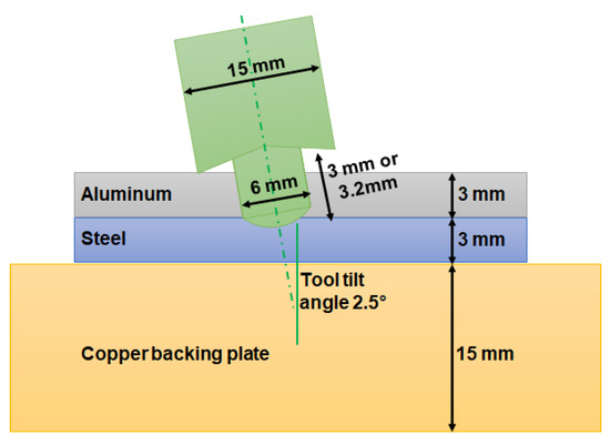
Figure 1.
Schematic diagram of the tool and workpeice FSP setup.
3. Results and Discussion
3.1. Macro and Microstructure Analysis
The microstructures of the base metals (low-carbon steel and aluminum) are shown in Figure 2. The microstructure of the low-carbon steel mainly consisted of equiaxed grains of a ferrite structure with a small amount of pearlite located at the grain’s boundaries, due to the low percentage of carbon, with an average grain size of ~60 μm as calculated using the linear intercept method (ASTM E112). The aluminum side exhibited large equiaxed grains in the rolling direction.
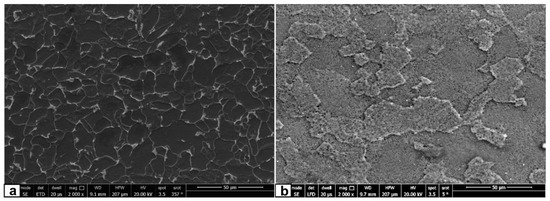
Figure 2.
Micrographs of the low-carbon steel (a) and pure aluminum base metals (b).
A typical unetched optical macrograph of the aluminum/steel interface processed at a medium rotation speed and a pin length of 1000 rpm and 3 mm is shown in Figure 3. Generally, an almost defect-free interface (i.e., no large defects such as voids and cracks) between plain the carbon steel and aluminum with limited intermixing between them is clearly visible. Only some steel fragments were spattered in a limited area near the interface on the aluminum side.
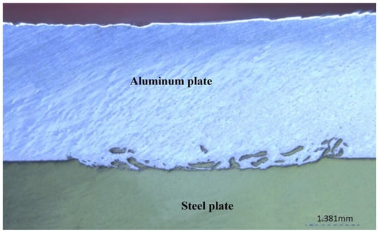
Figure 3.
Macrograph of the aluminum/steel interface produced with a medium FSP rotation speed of 1000 rpm and a pin length of 3 mm.
Figure 4 shows the SEM micrographs of the interface of the cladded zone processed at a high rotation speed of 1500 rpm and a pin length of 3 mm. Some laminated aluminum layers appear on the steel side and steel fragments appear on the aluminum side. This occurred in a limited thickness around the interface zone, resulting in a sandwich-like structure consisting of a layer of steel and a layer of aluminum. Some of these steel fragments were extracted during the metallographic preparations, as shown with red arrows in Figure 4d. In addition, the two original steel and aluminum mating surfaces completely disappeared, resulting in a sound-mixed interface without noticeable defects. As shown in Figure 5, different EDS mapping analyses were performed to confirm the SEM results. In order to further determine the composition of the laminated layer, an EDS analysis was performed at different locations of the boundaries of the layer in the magnified SEM image in Figure 6a. The ratio of Fe atoms and Al atoms is approximately equal to 2:5, which is sufficient for inducing the intermetallic compound of Fe2Al5. Since the XRD technique is considered the most accurate tool to identify phases such as intermetallic compounds, an XRD analysis was conducted, and Figure 7a shows the representative XRD patterns obtained from the samples processed at a high rotation speed of 1500 rpm. As expected, the patterns revealed that elemental Al and Fe represent the main peaks. However, a small percentage of Fe2Al5 intermetallics were also identified.
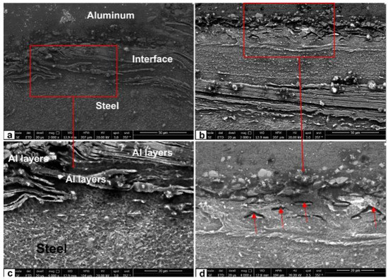
Figure 4.
SEM Micrographs of the aluminum/steel interface produced with high FSP rotation speed of 1500 rpm and pin length of 3 mm: (a) steel–aluminum interface, (b) the interface’s upper side, (c) the zoomed-in area of (a), and (d) the zoomed-in area of (b).
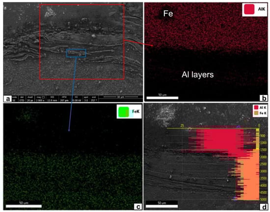
Figure 5.
EDS mapping of the aluminum/steel interface produced with high FSP rotation speed of 1500 rpm and pin length of 3 mm: (a) steel–aluminum interface, (b) EDS mapping for Al, (c) EDS mapping for Fe, and (d) relative ratio between Fe and Al in the interface.
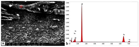
Figure 6.
EDS analysis of one of the layers located at the aluminum/steel interface produced with high FSP rotation speed of 1500 rpm and pin length of 3 m: (a) SEM image of one of the lamanater layers and (b) EDS analysis of the red box in (a).
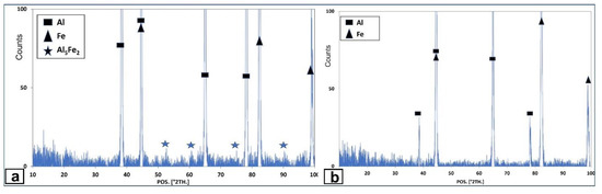
Figure 7.
XRD analysis of the aluminum/steel interface produced with FSP tool pin length of 3 mm and rotation speed of (a) 1500 rpm and (b) 1000 rpm.
However, at the medium rotation speed of 1000 rpm, and while keeping the pin length at 3 mm, some changes in the interface occurred, as shown in Figure 8. Blocky steel fragments with irregular shapes were completely separated from the steel side and randomly dispersed on the aluminum side, in addition to sticky fragments on the steel side. To confirm that these fragments were steel, an EDS-mapping analysis was performed, and its results are shown in Figure 8d. The steel fragments show deformed grains due to plastic deformation caused by the effect of the FSP tool’s stirring action. Moreover, the structure of these steel fragments still appears as a ferrite-pearlite structure. The pearlite phase can be easily identified, as shown by arrows in Figure 8a. This is evidence of the limited heat generated or the limited time this heat existed in this area. From the enlarged SEM micrographs (Figure 8b,c) and the XRD analysis in Figure 7b, there was no evidence that any intermetallic compounds appeared at the interface or at the edges of the steel fragments (at which they are expected to be formed). It is well known that the formation kinetics of intermetallic compounds depends mainly on temperature and time. Starting the formation of intermetallic compounds depends on reaching a specific temperature range, while the intermetallic compounds’ layer thickness depends mainly on the holding time at this temperature range [37]. Therefore, the relatively lower rotation speed and copper backing plate employed play a critical role in this case. Their use limits the maximum temperature during the bonding process and accelerates the cooling rate after it is within the processed region. In this case, the formation of most of the intermetallics will be limited. On the other hand, if they are formed, they will be exceptionally fine and present in a limited number. Moreover, since the tool pin does not penetrate the steel side (in the case of a 3 mm pin length, the pin will only touch the steel plate), most of the generated heat and the severe thermo-mechanical deformation will be concentrated in the upper part of the aluminum plate, where there are no steel fragments. According to the materials and the heat flow around the FSP tool, most of the generated heat during FSP will be under the shoulder and around the pin. Moreover, the excessive stirring and the severe thermoplastic deformation generated around the tool pin can accelerate the formation of intermetallic compounds. At the bottom of the pin, a limited amount of heat and plastic deformation will be generated to control the formation and propagation of intermetallics. Thus, the steel fragments that spattered around the Al–steel interface are located in what we can call a "safe zone", where a very low amount of heat is generated with a low level of plastic deformation. It is well known that the formation of thick intermetallics dramatically reduces the joint strength of Al-to-steel. Cracks were easily propagated when the intermetallic compounds were formed.
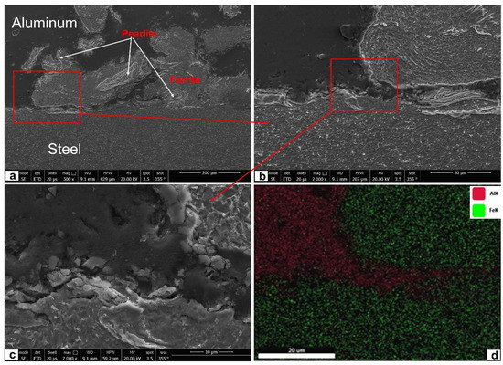
Figure 8.
SEM Micrographs of the aluminum/steel interface produced with medium FSP rotation speed of 1000 rpm and pin length of 3 mm: (a) steel–aluminum interface, (b) magnified area in (a), (c) magnified area in (b), and (d) EDS mapping of (c).
When the rotation speed was reduced to 500 rpm at the same pin length of 3 mm (Figure 9), the heat generated at the mating surface was not enough to form a sound interface. Almost two adjacent metals that did not bond were observed. Almost no steel fragments were observed on the aluminum side. Moreover, the oxide film that is usually found on the aluminum’s surface still occurred at the interface in a continuous form. Usually, when the FSP rotation speed is high enough, stirring action and tool pressure breaks the aluminum oxide film and distributes it inside the stirring zone [38].
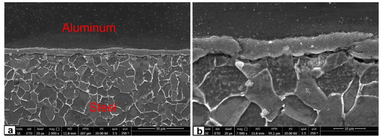
Figure 9.
SEM Micrographs of the aluminum/steel interface produced with low FSP rotation speed of 500 rpm and pin length of 3 mm: (a) steel–aluminum interface; (b) magnified image of the interface.
By increasing the tool pin length to 3.2 mm and under the same conditions of 500 rpm, a gap-like crack is observed exactly at the interface, as can be seen in Figure 10. Many cracks and cavities were observed in the aluminum side, especially around the steel fragments as shown by the red arrows in Figure 10b. Under this condition of a longer tool pin, the stir zone with its dynamic recrystallization occurred in the upper aluminum plate and in a small part of the steel side. Moreover, the thermo-mechanically affected zone and the heated affected zone can be easily noticed on the steel side owing to the resulting elevated temperature, as shown in the lower images of Figure 10a,c. A fine grain structure was found, especially in the recrystallization zone, which is considered a unique feature of FSP [35] Furthermore, there was no evidence of intermetallic compounds under these conditions despite the high mixing of both metals, as shown in the XRD results in Figure 11a.
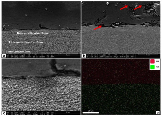
Figure 10.
SEM Micrographs of the aluminum/steel interface produced with low FSP rotation speed of 500 rpm and pin length of 3.2 mm: (a) steel–aluminum interface, (b) cavities and cracks around the steel fragments, (c) microsturcture of the steel side, and (d) EDS mapping of (c).
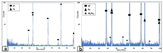
Figure 11.
XRD analysis of the aluminum/steel interface produced with FSP tool pin length of 3.2 mm and rotation speed of (a) 500 rpm and (b) 1500 rpm.
At a higher rotation speed of 1500 rpm with a longer tool pin of 3.2 mm, a dramatic change was observed due to the higher generated heat and high stirring action, as shown in the macro and micrographs of Figure 12. Macroscopically, many steel fragments were scattered within the stirred zone on the aluminum side as shown in Figure 12a. Some of the steel fragments were extracted during preparation, leaving holes, as shown by red arrows in Figure 12b. The magnified SEM micrographs (Figure 12b,c) show a similar sandwich-like laminated structure, which consists of layers of aluminum on the steel side and some fragments of steel on the aluminum side. Moreover, a few crack-like defects were observed in the recrystallized zone on the steel side, as shown by yellow arrows in Figure 12b. As expected, the XRD analysis detected that the peaks of Fe2Al5 intermetallics were more pronounced. The formation of the intermetallic compounds was occasioned by the presence of an elevated temperature at a higher rotational speed aided by the dynamic stirring action between the two metals associated with the longer pin, which increases the activity of the diffusing elements.
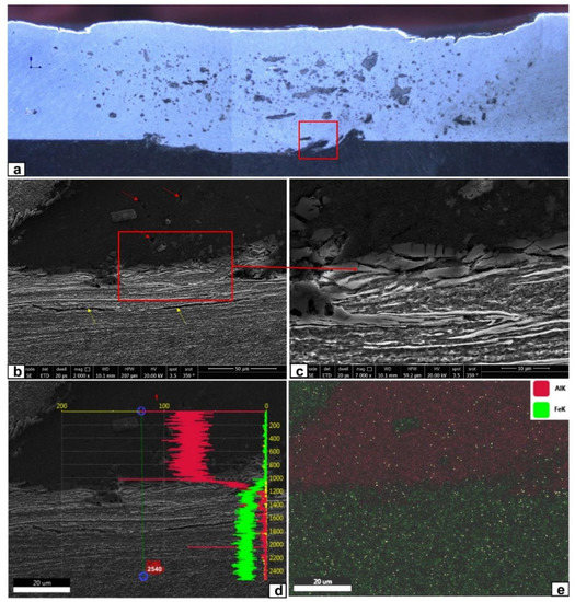
Figure 12.
Optical macrograph (a), SEM Micrograph (b,c), and EDS mapping (d,e) of the aluminum/steel interface produced with high FSP rotation speed of 1500 rpm and pin length of 3.2 mm.
With the help of the ThermoCalc® software, many intermetallic compounds are thermodynamically expected to be formed in the equilibrium state between the aluminum and ferrite phases (with ~0.01% C) at temperatures below 500 °C (such as Al2Fe, Fe4Al13, Al4C3, and AlFe3C), as shown in Figure 13a. In addition, the dissolution of aluminum and pearlite phase (with 0.8% C) at temperatures below 500 °C may result in the formation of intermetallic compounds (such as Al4C3, Fe4Al13, AlFe3C, cementite, diamond, and their mixture) as shown in Figure 13b. The kinetics of the formation and growth of these phases depends on triangle parameters: the existence of iron, carbon, and aluminum; reaching specific temperatures; and maintaining such temperatures for some time. Using copper—with an excellent thermal conductivity—as a backing plate will absorb most of the generated heat and accelerate the cooling rate, which breaks one or two parameters of these triangle parameters. Firstly, it reduces the maximum temperature that the metal reaches. Then, the accelerated cooling rate will reduce the time at which the metals stay at elevated temperatures. Therefore, the formation of an intermetallic compound is kinetically unfavorable in the current process setup. This will reduce the chance of the formation of these intermetallic compounds; if they are formed, they will be present in an extremely limited number.
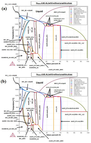
Figure 13.
ThermoCalc® software phase diagram of (a) ferrite composition (Fe with 0.01 C%) of Aluminum and (b) the perlite composition for Fe with 0.8 C% Aluminum, without graphite formation.
However, the severe plastic deformation associated with the FSP can accelerate the formation of these intermetallics. In this case, using a shorter pin, which has a length that matches the thickness of the upper aluminum plate and will not penetrate the lower steel part, helps to reduce the amount of steel that will mix inside the aluminum part. This will limit the dissimilar metal’s contact to a limited area.
3.2. Mechanical Properties
The tool’s length and the rotational speed were varied from 3 to 3.2 mm and from 500 to 1500 rpm, respectively, at a fixed feed rate of 100 mm/min, to optimize the mechanical strength of the cladded joint. Figure 14 shows the effect of the investigated different rotation speeds and tool pin lengths on the tensile shear load of the cladded systems. Measuring the tensile shear strength is exceedingly difficult due to the irregular shape area of the formed nugget. The maximum tensile shear load was obtained at a rotation speed of 1500 rpm and a tool pin length of 3.2 mm. This is due to the thicker mixing areas at a higher rotational speed that support the cladding system and resist the applied load. In addition, this phenomenon can be related to the ability of the limited amount of brittle intermetallic compounds formed—with a good agreement with the XRD results—to severely affect the failure mode. The resulting tensile shear load decreases with decreasing the rotation speed at a fixed tool pin length. The tensile load of a rotation speed of 1000 rpm was much closer to that of 1500 rpm. At a rotation speed of 500 rpm, the tensile shear load was lower than the other processing parameters. This is due to cracks and debonding areas in the interface. Meanwhile, the cladded samples processed with a longer pin length (3.2 mm) at a higher rotational speed (1500 rpm) tend to exhibit a higher interface shear load. This may be due to the wider interface-mixed area. However, we expect a lower interface shear strength under this condition due to the formation of an intermetallic compound—with its brittle nature—in the interface, which deteriorates the mechanical properties.
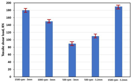
Figure 14.
Tensile shear load of the aluminum/steel interface produced with different FSP rotation speeds and pin lengths.
The hardness profiles of the nuggets’ cross-sections with respect to the thickness direction produced by different rotational speeds and tool pin lengths are shown in Figure 15. The measurements were conducted along a vertical line approximately at the middle of the nugget. Generally, the interface shows a higher hardness compared with both the steel and aluminum base metals. Moreover, all hardness values of the friction stir-processed upper aluminum plate (far from the interface) were higher than the used aluminum base metal (42 HV). This is due to the recrystallized microstructure with relatively fine grains resulting in intense plastic deformation caused by the tool’s rotation and shoulder pressure. In addition, the faster cooling rates through the copper backing plate significantly affect the structural refinement. The decreasing rotation speed will decrease the generated temperature and consequently decrease the grain size. This grain refinement has a significant contribution to this hardness increment.
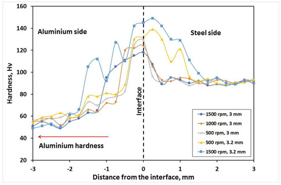
Figure 15.
Hardness distribution of the aluminum/steel interface produced with different FSP rotation speeds and pin lengths.
At the interface, two different trends were observed at different pin lengths, as shown in Figure 16. At a pin length of 3 mm, the hardness increased with decreasing the rotational speed. On the other hand, at a pin length of 3.2 mm, increasing the rotational speed increased the interface hardness. This can be related to the high mixing action at a 3.2 mm pin length, which increased the generated heat and induced the formation of IMC (see XRD chart Figure 11b), thereby increasing the hardness with the increasing rotation speed. On the other hand, at a shorter pin length of 3 mm, the amount of heat generated increased with the increasing rotation speed, which caused coarsening in the microstructure and reduced the hardness.
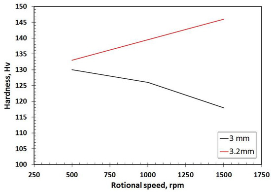
Figure 16.
The relationship between hardness, rotation speed, and pin lengths.
In addition, when the tool pin length was increased to 3.2 mm, a remarkable hardness increment was noticed around the interface on both the aluminum and steel sides. For the aluminum side, the hard aluminum-rich intermetallic compounds contribute to the hardness increment. The steel side suffers from the thermomechanical deformation imposed by the FSP tool, which reaches the steel at an increased tool pin length.
4. Conclusions
The present work aimed to clad 3 mm thick plates of pure aluminum and low-carbon steel through friction stir processing. Single-pass FSP techniques with different rotation speeds in the range of 500–1500 rpm were applied at a fixed feed rate of 100 mm/min. Tool pin lengths of 3 mm and 3.2 mm were used. A 15 mm thick pure copper backing plate was used. The macro- and microstructures of the FSP interface were investigated in addition to other mechanical behaviors. The following conclusions were obtained:
- The cladding of low-carbon steel/pure aluminum with a limited intermixing layer was successfully performed through friction stir processing without noticeable defects or cracks and at rotational speeds of more than 500 rpm.
- The pure copper backing plate significantly aided in reducing/eliminating the formation of intermetallic compounds in the cladding interface.
- Using a tool pin length equal to the upper plate (3 mm) produces a sound cladding interface that appears as laminated layers at more than 500 rpm rotation speeds. A limited number of Fe2Al5 intermetallics were formed at a rotation speed of 1500 rpm, while no intermetallics were detected at 1000 rpm. The rotation speed of 500 rpm was not enough to mix the two mating metals and form a sound cladding interface.
- When the tool pin length was longer than the upper plate (3.2 mm), many steel fragments were scattered within the aluminum side, forming a laminated sandwich structure. Some Fe2Al5 intermetallics were formed, especially at a rotation speed of 1500 rpm.
- The tensile shear load decreases when decreasing the rotation speed and increasing the tool pin length. The maximum tensile shear load was obtained at a rotation speed of 1500 rpm and a tool pin length of 3.2 mm.
- The hardness values of the interface were higher than the aluminum base metal for all the investigated samples. Decreasing the rotation speed and increasing the tool pin length will lead to a hardness increment.
Author Contributions
Conceptualization, E.R.I.M., S.Z.K., M.A.E. and S.E.; methodology, E.R.I.M., A.A. and H.A.; software, E.R.I.M., M.A.G. and S.E.; validation, E.R.I.M., S.Z.K. and S.E.; formal analysis, E.R.I.M., M.A.E., M.A.G. and S.E.; investigation, E.R.I.M., S.Z.K. and S.E.; resources, E.R.I.M., S.Z.K. and S.E.; data curation, M.A.E.; writing—original draft preparation, E.R.I.M., S.Z.K. and S.E.; writing—review and editing, E.R.I.M., S.Z.K. and S.E.; visualization, E.R.I.M., M.A.E., M.A.G. and S.E.; supervision, E.R.I.M., S.Z.K. and S.E.; project administration, S.Z.K., A.A. and H.A.; funding acquisition, S.Z.K. All authors have read and agreed to the published version of the manuscript.
Funding
The authors would like to express their appreciation for the support provided by the Scientific Research Deanship, the Islamic University of Madinah, through the research program Tamayuz-2 with the grant number 703.
Data Availability Statement
The authors confirm that the data supporting the findings of this study are available within the article.
Conflicts of Interest
The authors declare no conflict of interest.
References
- Mori, K.I.; Abe, Y. A Review on Mechanical Joining of Aluminium and High Strength Steel Sheets by Plastic Deformation. Int. J. Light. Mater. Manuf. 2018, 1, 1–11. [Google Scholar] [CrossRef]
- Sun, J.; Yan, Q.; Gao, W.; Huang, J. Investigation of Laser Welding on Butt Joints of Al/Steel Dissimilar Materials. Mater. Des. 2015, 83, 120–128. [Google Scholar] [CrossRef]
- Schubert, E.; Klassen, M.; Zerner, I.; Walz, C.; Sepold, G. Light-Weight Structures Produced by Laser Beam Joining for Future Applications in Automobile and Aerospace Industry. J. Mater. Process. Technol. 2001, 115, 2–8. [Google Scholar] [CrossRef]
- Hartley, W.D.; Garcia, D.; Yoder, J.K.; Poczatek, E.; Forsmark, J.H.; Luckey, S.G.; Dillard, D.A.; Yu, H.Z. Solid-State Cladding on Thin Automotive Sheet Metals Enabled by Additive Friction Stir Deposition. J. Mater. Process. Technol. 2021, 291, 117045. [Google Scholar] [CrossRef]
- P.J. Honda Develops New Technology to Weld Together Steel and Aluminum and Achieves World’s First Application to the Frame of a Mass-production Vehicle-Hybrid-Structured Front Subframe Achieves Both Weight Reduction and Increased Rigidity. 2012. Available online: https://www.thefreelibrary.com/Honda+Develops+New+Technology+to+Weld+Together+Steel+and+Aluminum+and...-a0302006358 (accessed on 16 September 2022).
- Ahmet Efe, A.I. A General View of Industry 4.0 Revolution from Cybersecurity Perspective. Int. J. Intell. Syst. Appl. Eng. 2020, 8, 11–20. [Google Scholar] [CrossRef]
- Chen, G.; Li, J.; Xu, G. Bonding Process and Interfacial Reaction in Horizontal Twin-Roll Casting of Steel/Aluminum Clad Sheet. J. Mater. Process. Technol. 2017, 246, 1–12. [Google Scholar] [CrossRef]
- Gullino, A.; Matteis, P.; Aiuto, F.D. Review of Aluminum-to-Steel Welding Technologies for Car-Body Applications. Metals 2019, 9, 315. [Google Scholar] [CrossRef]
- Corigliano, P.; Crupi, V.; Guglielmino, E. Non Linear Finite Element Simulation of Explosive Welded Joints of Dissimilar Metals for Shipbuilding Applications. Ocean Eng. 2018, 160, 346–353. [Google Scholar] [CrossRef]
- Carvalho, G.H.S.F.L.; Galvão, I.; Mendes, R.; Leal, R.M.; Loureiro, A. Formation of Intermetallic Structures at the Interface of Steel-to-Aluminium Explosive Welds. Mater. Charact. 2018, 142, 432–442. [Google Scholar] [CrossRef]
- Title of Dissertation: Effect of Microstructure on the Room. Science.
- Dehghani, M.; Amadeh, A.; Akbari Mousavi, S.A.A. Investigations on the Effects of Friction Stir Welding Parameters on Intermetallic and Defect Formation in Joining Aluminum Alloy to Mild Steel; Elsevier Ltd.: Amsterdam, The Netherlands, 2013; Volume 49, ISBN 9821820840. [Google Scholar]
- Sharma, A.; Morisada, Y.; Fujii, H. Influence of Aluminium-Rich Intermetallics on Microstructure Evolution and Mechanical Properties of Friction Stir Alloyed Al–Fe Alloy System. J. Manuf. Process. 2021, 68, 668–682. [Google Scholar] [CrossRef]
- Wang, T.; Sidhar, H.; Mishra, R.S.; Hovanski, Y.; Upadhyay, P.; Carlson, B. Evaluation of Intermetallic Compound Layer at Aluminum/Steel Interface Joined by Friction Stir Scribe Technology. Mater. Des. 2019, 174, 107795. [Google Scholar] [CrossRef]
- Liu, W.; Ma, J.; Mazar Atabaki, M.; Kovacevic, R. Joining of Advanced High-Strength Steel to AA 6061 Alloy by Using Fe/Al Structural Transition Joint. Mater. Des. 2015, 68, 146–157. [Google Scholar] [CrossRef]
- Yang, Y.; Zhang, F.; He, J.; Qin, Y.; Liu, B.; Yang, M.; Yin, F. Microstructure, Growth Kinetics and Mechanical Properties of Interface Layer for Roll Bonded Aluminum-Steel Clad Sheet Annealed under Argon Gas Protection. Vacuum 2018, 151, 189–196. [Google Scholar] [CrossRef]
- Su, S.; Chen, S.; Mao, Y.; Xiao, J.; Vivek, A.; Daehn, G. Joining Aluminium Alloy 5A06 to Stainless Steel 321 by Vaporizing Foil Actuators Welding with an Interlayer. Metals 2019, 9, 43. [Google Scholar] [CrossRef]
- Li, L.; Nagai, K.; Yin, F. Progress in Cold Roll Bonding of Metals. Sci. Technol. Adv. Mater. 2008, 9. [Google Scholar] [CrossRef] [PubMed]
- Zhao, Y.Y.; Zhang, Z.Y.; Jin, L.; Dong, J. Effects of Annealing Process on Sagging Resistance of Cold-Rolled Three-Layer Al Alloy Clad Sheets. Trans. Nonferrous Met. Soc. China 2016, 26, 2542–2551. [Google Scholar] [CrossRef]
- Grydin, O.; Gerstein, G.; Nürnberger, F.; Schaper, M.; Danchenko, V. Twin-Roll Casting of Aluminum-Steel Clad Strips. J. Manuf. Process. 2013, 15, 501–507. [Google Scholar] [CrossRef]
- Chen, G.; Li, J.T.; Yu, H.L.; Su, L.H.; Xu, G.M.; Pan, J.S.; You, T.; Zhang, G.; Sun, K.M.; He, L.Z. Investigation on Bonding Strength of Steel/Aluminum Clad Sheet Processed by Horizontal Twin-Roll Casting, Annealing and Cold Rolling. Mater. Des. 2016, 112, 263–274. [Google Scholar] [CrossRef]
- Akramifard, H.R.; Mirzadeh, H.; Parsa, M.H. Cladding of Aluminum on AISI 304L Stainless Steel by Cold Roll Bonding: Mechanism, Microstructure, and Mechanical Properties. Mater. Sci. Eng. A 2014, 613, 232–239. [Google Scholar] [CrossRef]
- Wu, B.; Li, L.; Xia, C.; Guo, X.; Zhou, D. Effect of Surface Nitridingtreatment in a Steel Plate on the Interfacial Bonding Strength of the Aluminum/Steel Clad Sheets by the Cold Roll Bonding Process. Mater. Sci. Eng. A 2017, 682, 270–278. [Google Scholar] [CrossRef]
- Carvalho, G.H.S.F.L.; Galvão, I.; Mendes, R.; Leal, R.M.; Loureiro, A. Explosive Welding of Aluminium to Stainless Steel. J. Mater. Process. Technol. 2018, 262, 340–349. [Google Scholar] [CrossRef]
- Findik, F. Recent Developments in Explosive Welding. Mater. Des. 2011, 32, 1081–1093. [Google Scholar] [CrossRef]
- Sun, X.J.; Tao, J.; Guo, X.Z. Bonding Properties of Interface in Fe/Al Clad Tube Prepared by Explosive Welding. Trans. Nonferrous Met. Soc. China 2011, 21, 2175–2180. [Google Scholar] [CrossRef]
- Mohammad Kazem Besharati Givi and Parviz Asadi 1- General Introduction. In Advances in Friction-Stir Welding and Processing; Elsevier: Amsterdam, The Netherlands, 2014; pp. 1–19.
- Padhy, G.K.; Wu, C.S.; Gao, S. Friction Stir Based Welding and Processing Technologies—Processes, Parameters, Microstructures and Applications: A Review. J. Mater. Sci. Technol. 2018, 34, 1–38. [Google Scholar] [CrossRef]
- Mishra, R.S.; Ma, Z.Y. Friction Stir Welding and Processing. Mater. Sci. Eng. R Rep. 2005, 50, 1–78. [Google Scholar] [CrossRef]
- Ibrahim, A.B.; Al-Badour, F.A.; Adesina, A.Y.; Merah, N. Effect of Process Parameters on Microstructural and Mechanical Properties of Friction Stir Diffusion Cladded ASTM A516-70 Steel Using 5052 Al Alloy. J. Manuf. Process. 2018, 34, 451–462. [Google Scholar] [CrossRef]
- Zhang, G.; Su, W.; Zhang, J.; Wei, Z. Friction Stir Brazing: A Novel Process for Fabricating Al/Steel Layered Composite and for Dissimilar Joining of Al to Steel. Metall. Mater. Trans. A Phys. Metall. Mater. Sci. 2011, 42, 2850–2861. [Google Scholar] [CrossRef]
- Mahmoud, E.R.I.; Al-qozaim, A.M.A. Fabrication of In-Situ Al–Cu Intermetallics on Aluminum Surface by Friction Stir Processing. Arab. J. Sci. Eng. 2016, 41, 1757–1769. [Google Scholar] [CrossRef]
- Mahmoud, E.R.I.; Takahashi, M.; Shibayanagi, T.; Ikeuchi, K. Wear Characteristics of Surface-Hybrid-MMCs Layer Fabricated on Aluminum Plate by Friction Stir Processing. Wear 2010, 268, 1111–1121. [Google Scholar] [CrossRef]
- Lee, C.Y.; Choi, D.H.; Yeon, Y.M.; Jung, S.B. Dissimilar Friction Stir Spot Welding of Low Carbon Steel and Al-Mg Alloy by Formation of IMCs. Sci. Technol. Weld. Join. 2009, 14, 216–220. [Google Scholar] [CrossRef]
- Mirzadeh, H. High Strain Rate Superplasticity via Friction Stir Processing (FSP): A Review. Mater. Sci. Eng. A 2021, 819, 141499. [Google Scholar] [CrossRef]
- Mahmoud, E.R.I.; Takahashi, M.; Shibayanagi, T.; Dceuchi, K. Fabrication of Surface-Hybrid-MMCs Layer on Aluminum Plate by Friction Stir Processing and Its Wear Characteristics. Mater. Trans. 2009, 50, 1824–1831. [Google Scholar] [CrossRef]
- Ritti, L.; Bhat, T. Design and Numerical Analysis of Tool for FSP Simulation of Magnesium Alloys. Mater. Today Proc. 2021, 46, 2489–2497. [Google Scholar] [CrossRef]
- Chen, Y.C.; Nakata, K. Effect of the Surface State of Steel on the Microstructure and Mechanical Properties of Dissimilar Metal Lap Joints of Aluminum and Steel by Friction Stir Welding. Metall. Mater. Trans. A Phys. Metall. Mater. Sci. 2008, 39, 1985–1992. [Google Scholar] [CrossRef]
Publisher’s Note: MDPI stays neutral with regard to jurisdictional claims in published maps and institutional affiliations. |
© 2022 by the authors. Licensee MDPI, Basel, Switzerland. This article is an open access article distributed under the terms and conditions of the Creative Commons Attribution (CC BY) license (https://creativecommons.org/licenses/by/4.0/).