Article

Terahertz Refractive Index Sensor Based on Enhanced Extraordinary Optical Transmission

1
School of Microelectronics, Shandong University, Jinan 250100, China
2
Engineering Research Center for Semiconductor Integrated Technology, Institute of Semiconductors, Chinese Academy of Sciences, Beijing 100083, China
*
Author to whom correspondence should be addressed.
Crystals 2022, 12(11), 1616; https://doi.org/10.3390/cryst12111616
Submission received: 26 October 2022 / Revised: 8 November 2022 / Accepted: 8 November 2022 / Published: 11 November 2022
(This article belongs to the Special Issue Terahertz Metamaterials and Active Modulation)

Abstract

:
This paper presents a structure for refractive index sensors in the terahertz (THz) band. The THZ sensor is studied in simulation, utilizing the strong local electromagnetic field intensity produced by the enhanced extraordinary optical transmission. Depending on the different sensing positions of the sensor, their sensing basis is also different, such as Mie scattering, surface plasmon polaritons, etc. The sensing sensitivity based on Mie scattering can reach 51.56 GHz/RIU; meanwhile the sensing sensitivity based on surface plasmon polaritons is only 5.13 GHz/RIU. The sensor can also detect the thickness of the analyte, with the lowest detectable height of 0.2 µm. Additionally, we find that the sensitivity can be increased by replacing the silicon particle with the analyte.

1. Introduction

“THz wave” refers to an electromagnetic wave with a 0.1 THz–10 THz frequency. The photon energy of 1 THz is only about 4.14 meV, which means that it will not ionize biological molecules and will cause little radiation damage to tissues and organs in living organisms. Ref. [1] reports that THz waves are of great research value in the biological field. Based on the excellent characteristics of the THz band, the THz sensor is an important technology that has developed in recent years, to the extent that it now touches many areas from fundamental science to real-world applications, such as biomedicine [2,3], food safety [4,5], environmental monitoring [6], industry and agriculture [7,8]. The terahertz metamaterials sensor is an emerging technology, which is based on a surface plasmon polaritons (SPPs)-like effect, which explains the possibility of generating SPPs in the terahertz frequency range. Pendry et al. proposed a method of forming an array of periodic slits and holes on the metal surface to achieve spoof surface plasma [9]. The dispersion relationship of spoof surface plasma can be adjusted by adjusting the structure and size of devices, which has gradually become a research hotspot in the field of THz sensing. Ng B. et al. used metal groove arrays with subwavelength periods to excite spoof surface plasma to measure THz spectrum phase and amplitude changes of gasoline, and obtained a high sensitivity. In Ref. [7] Ying et al. used terahertz metamaterials to detect the pesticide chlorpyrifos methyl and achieved a sensing accuracy of 0.204 mg/L. In Ref. [4], Chau et al. proposed a refractive index sensor of multimode Fano resonance based on cavity/gap plasmon resonance, achieving remarkable high-sensitivity. In Ref. [10], by taking full advantage of the properties of surface plasmons, the performance of THz sensors can be effectively improved. Extraordinary optical transmission (EOT) refers to the resonant transmission of electromagnetic radiation through a metal film with a subwavelength aperture. According to the theory of diffraction by small holes, if the hole radius r is much smaller than the incident wavelength, the transmittance is close to zero [11,12,13,14,15,16,17,18,19,20] However, in practice, if the incident light passes through a subwavelength metal hole, the transmittance is much higher than the theory predicts, which is called EOT. [16,17,18,19,20,21,22,23,24,25] The extraordinary optical transmission (EOT) phenomenon results from SPPs, which are a type of surface electromagnetic wave. SPPs are generated by coupling excitation of clusters of oscillating free electrons propagating along the metal-dielectric surface and can greatly improve transmittance [13] The enhanced extraordinary optical transmittance (EEOT) phenomenon can be realized by placing two silicon particles on both sides of subwavelength hole arrays [16,17,18,19,20,21,22,23,24,25], because the energy coupled by silicon particles can be effectively coupled with the SPPs and improve the transmittance.
If low-loss silicon particles are placed symmetrically on both sides of the hole, the enhanced extraordinary optical transmittance (EEOT) phenomenon will be greater. The silicon particles can be regarded as magnetic dipole antennas, which effectively guide the incoming electromagnetic waves to the subwavelength aperture and then transmit them to the free space through Mie resonance coupling. The top silicon particle can couple electromagnetic energy, the hole array excites the SPPs and the bottom silicon particle can distribute the energy. Although the radius of the hole array is much less than the incident wavelength, there is still a large transmittance [16,17]. Low energy THz waves can be enhanced by the EEOT phenomenon. In the structure using two silicon resonators, the enhanced transmittance peak is sensitive to the external dielectric environment, as there is a very strong electromagnetic field inside the hole. Small changes in the analyte can produce a large frequency shift in the transmittance peak, which can be applied to the development of THz sensors [1,11,12,13,14,15,16,17].
In this work, we propose a THz sensor, taking advantage of the EEOT phenomenon. We tested by placing the analytes in three different positions: over a silicon particle, to one side of a particle and in between two particles. The transmittance was greatest when the analyte was covering a particle. The radius of the hole array also had an impact on the sensitivity S n . As the radius increased, the sensitivity decreased. In addition, as the height of the analyte changed, the frequency of the transmittance peak changed. The lowest detectable height change was 0.2 µm. Moreover, we found that, if a silicon particle was replaced with the analyte, forming an analyte-hole-silicon particle asymmetric structure, there was better sensitivity. This enables the sensing of small volume analytes, which have a significant application potential in biomedical sensing.

2. Materials and Methods

A subwavelength hole with radius r of 4.5 µm in a gold film is shown in Figure 1a. The Au film thickness was 1 µm, which is much larger than the skin depth and opaque to the incident plane wave. The Au film length and width were both 50 µm. Ref. [16] The sensor is shown in Figure 1b. The silicon particles are placed on the upper and lower sides of the hole and the analyte covers the upper silicon particle. The silicon particle height h 0 was 4 µm and the silicon particle width w 0 and length l 0 were both 12 µm. The optical constants of Au and Si are quoted from the CRC model and the Palik model, respectively [26]. The analyte height h was 5 µm, width w was 12 µm and length l was 50 µm.
Our work depends on a commercial piece of software, the finite-difference time-domain (FDTD) solutions 2020, which uses a discrete method to turn Maxwell’s equations into difference equations [14]. A perfectly matched layer boundary condition was used in the x direction and periodic boundary conditions were placed in the y and z directions. A spatial step discretization of 0.8 × 0.8 × 0.1 µ m 3 , a running time of 800 ps and an auto-shutoff minimum of 1 × 10 6 in the simulations were adopted to trade off accuracy and running time. A plane wave source propagated along the x direction with an electric field polarized along the y direction [16]. In order to reflect the sensing performance, we took sensitivity S n as a measure, which is defined as S n = Δ f 0 / Δ n   [13] or S n = Δ f 0 / Δ h , where Δ f 0 is the frequency shift of the transmittance peak, Δ n is the refractive index shift for different analytes and Δ h is the height change for the same analytes.

3. Results and Discussion

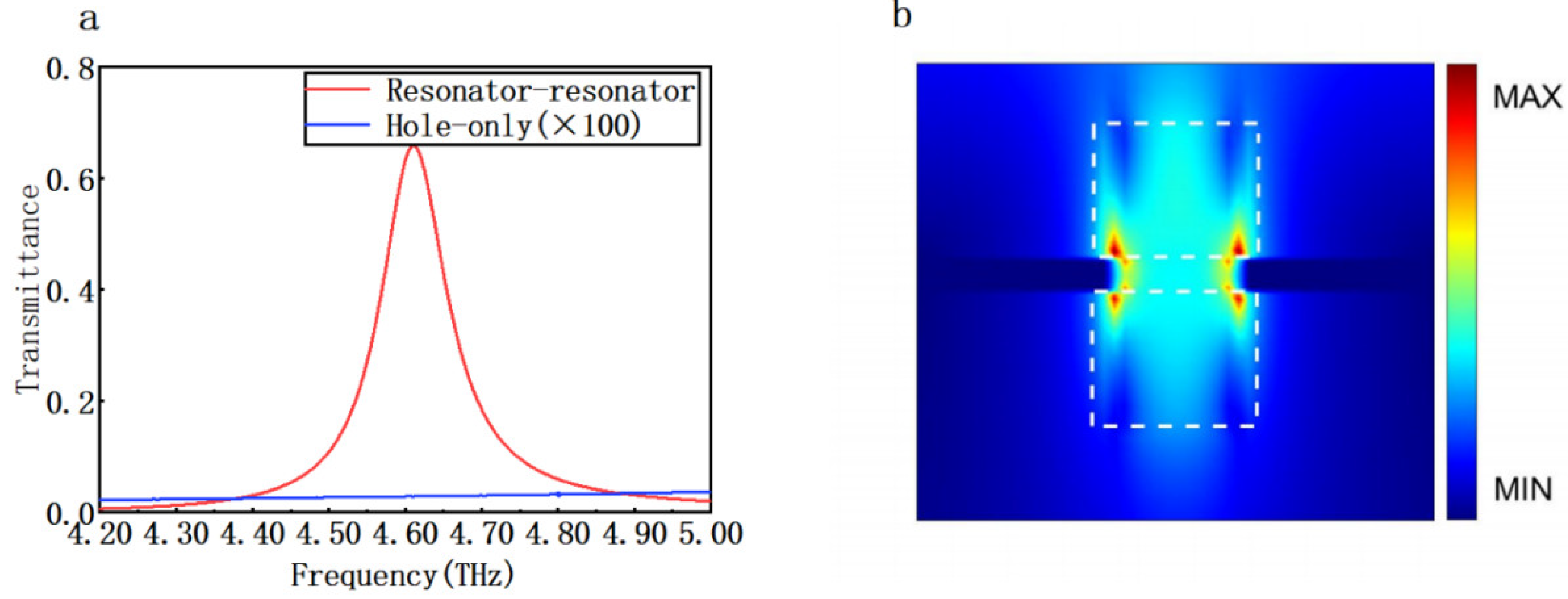
The transmittance characteristics of the EEOT structure are shown in Figure 2a. The blue line shows the transmittance of the hole-only structure of Figure 1a, which shows that light can hardly get through. According to the theory of hole transmittance, the transmission efficiency through a small hole scales with the ratio of r/λ. Refs. [4,7] The red line shows the transmittance of the silicon-hole-silicon structure. The transmittance peak can achieve 0.68, which is much larger than hole transmittance theory predicts. The transmittance peak occurs at 4.61 THz.
The electric field distribution is shown in Figure 2b. As shown in the figure, there is a larger electric field intensity at the edge of the metal hole and between the silicon particles. Surface plasmon polaritons (SPPs), which are an electromagnetic surface wave traveling along the interface separating a dielectric and a metal, play a key role in the production of EOT [16,17,18,19,20,21,22,23,24,25]. The metal hole reflects a high electric field intensity. The energy collected by Mie resonance can usefully be coupled with SPPs and generate a high electric field intensity in the coupling area. The silicon can be considered as a magnetic dipole antenna, which can couple incident THz waves, collect the energy of the incident wave, and guide it to the metal hole array and exciting LSP. The upper surface plasmon polaritons excite the local surface plasmon polaritons of the underlying metal on both sides of the hole. The bottom silicon particle can release the energy of the electromagnetic wave. The internal current between the silicon particles and the subwavelength holes depicts the excitation of the circulating current throughout the structure, which ultimately suggests that the magnetic dipole resonance generated in the silicon particles and the excited SPPs near the hole array together contribute to the EEOT. So the silicon particles reflect a high electric field intensity [16,21,22,27].
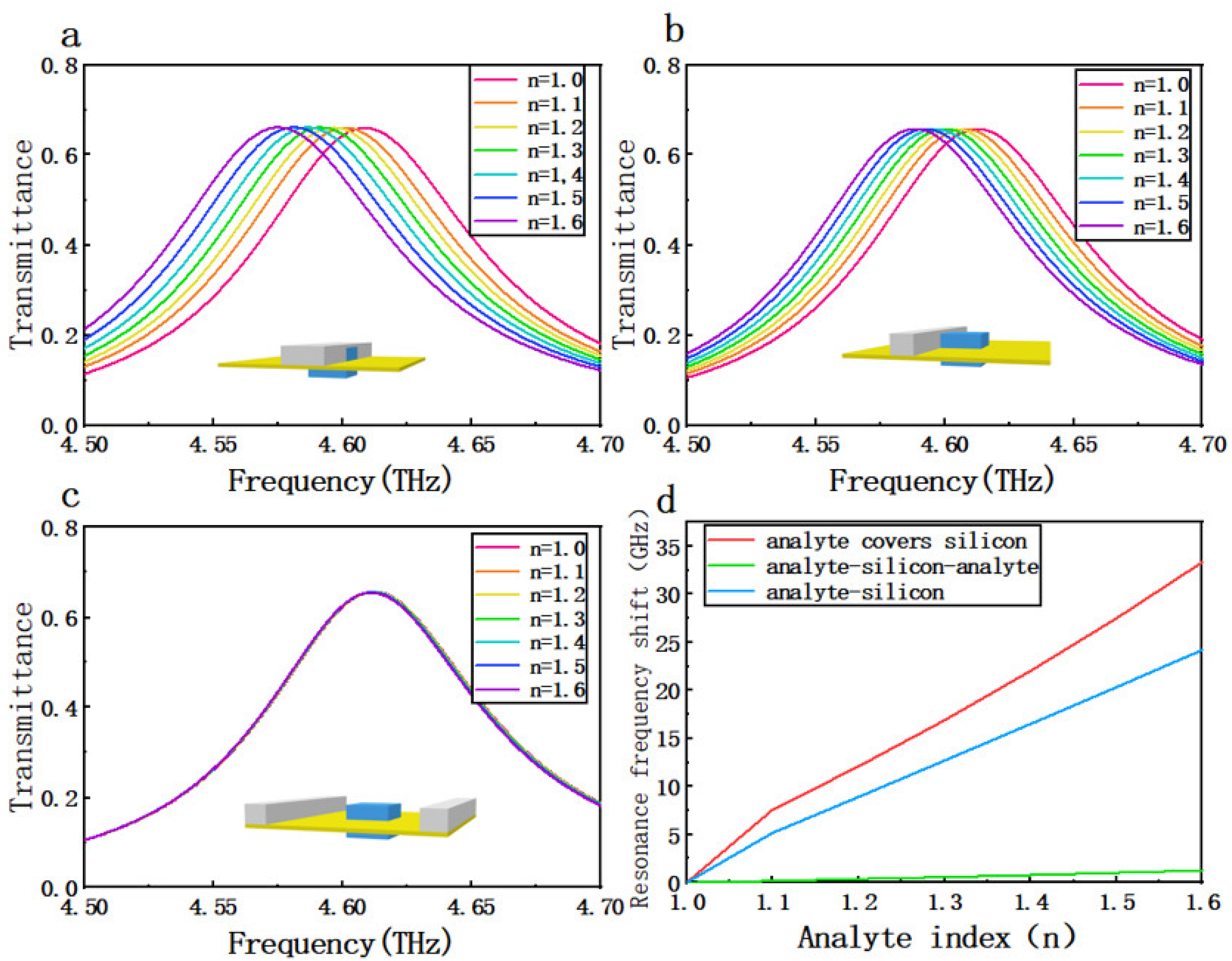
The analyte and silicon particles were arranged in three different configurations and the transmittance measured and compared. As shown in Figure 3a–c, by increasing the refractive index n of the analyte, the resonance frequencies exhibited a remarkable red-shift. This shows that frequency shift can indicate the refractive index of the analyte. The analyte height h is 5 µm, width w is 12 µm, and length l is 50 µm. As shown in Figure 3d, the frequency shift changes relatively smoothly as the analyte refractive index increases from 1.1 to 1.6. Comparing the three configurations, it can be seen that, when the analyte is covered with the silicon particles, the sensitivity is greatest. As the refractive index changes from 1.1 to 1.6, the frequency shift is 25.78 GHz and the sensitivity S n is about 51.56 GHz/RIU. When the analyte is placed on either side of the silicon particle, as in Figure 3c, the sensitivity approaches zero. When the refractive index changes from 1.1 to 1.6, the frequency shift is 1.09 GHz, and the sensitivity S n is about 2.18 GHz/RIU. When the analyte is on one side of a silicon particle, as in Figure 3b, the parameters are in the middle. The refractive index of typical biomedical samples is between 1.3 and 1.4. [6,28]. When the refractive index of the analyte is between 1.3 and 1.4, the sensitivity of the analyte-covered silicon structure and analyte-silicon structure is 5.13 GHz/RIU and 3.82 GHz/RIU. The frequency of transmittance peak shift is clear. The sensor can therefore act as a super-sensitive biosensor [28,29,30,31,32,33,34,35,36].
In order to further study the factors affecting sensitivity, the transmittance spectra were simulated for a metal hole array with diameter d of 7 µm, 9 µm, and 11 µm (Figure 4a–c). As observed above, this shows that the refractive index can be sensed by frequency shift. The frequency shift also depends on the metal hole diameter. As Figure 4d shows, as d increased, the sensitivity S n decreased. Furthermore, if the diameter is reduced to increase sensitivity, the transmittance peak will decrease, which will improve recognition difficulty. If the radius of the hole increases, the local coupling area increases, and the transmittance will increase (according to the theory of diffraction by small holes) [20,27]. In addition, if the local coupling area decreases, the coupling between SPPS and SPR is strengthened, the local electric field near the metal hole is enhanced, and the metal hole will be more sensitive to external electric field changes. The available range of the hole diameter is about 5–15 μm. The performance of this EEOT THz sensor shows great promise.
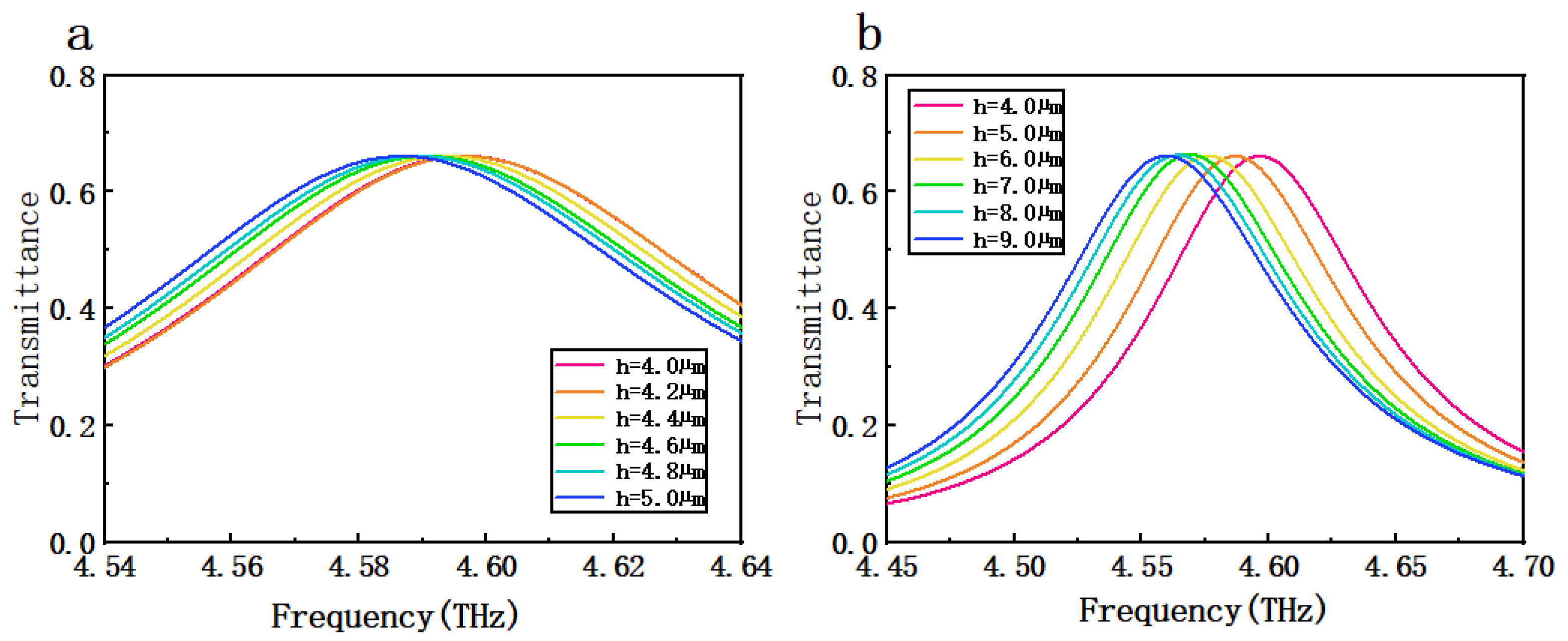
We also found a possibility of detecting the height h of the analyte. As Figure 5a shows, the lowest detectable height change was 0.2 µm. When the height changed from 4.0 µm to 5.0 µm, the frequency shift was 9.72 GHz and the sensitivity S n was about 9.72 GHz/µm. We found it easy to distinguish different substances using the frequency of transmittance peak shift. The high sensitivity to small height changes means this sensor can sense analytes of the size of cell tissues, which are always submicron. The EEOT sensor has the potential for applications in biological sensing. If the height changes from 4.0µm to 9.0µm as in Figure 5b, the frequency shift is 38.27 GHz and the sensitivity S n is about 7.65 GHz/µm. Moreover, when the height is relatively large, there is a smaller S n , which means the sensor is not applicable to a larger analyte.
Based on the principle of EEOT, we found the possibility of increasing S n . The top silicon particle works as an antenna. So if the top silicon particle is replaced with the analyte, there will be a significant frequency of transmittance peak shift and transmittance peak shift. As the Figure 6 shown, when the analyte refractive index changed from 1.1 to 1.6, the frequency shift was 56.59 GHz and the S n was 113.18 GHz/RIU. Additionally, the transmittance was weak. The particle acted as a receiving antenna to efficiently capture the incident energy, generating a strong magnetic field in the center of the silicon particle. Due to the lack of a magnetic dipole resonator on the other side of the hole, the asymmetric structure could not couple all the localized electromagnetic fields, so the energy transmitted through the subwavelength aperture was relatively weak. A part of the energy that was localized in the particle was absorbed, reflected, or lost during the propagation between the particle and the hole [16]. Moreover, the transmittance peak will increase as the refractive index increases, which may offer a new method for sensing. However, the structure is difficult to build and the volume of the analyte is small, which means this structure can be further improved.

4. Conclusions

By placing two low-loss silicon particles symmetrically on either side of subwavelength holes, greatly enhanced THz EOT has been obtained. The Mie resonance coupling between a pair of magnetic dipole resonators can effectively localize electromagnetic fields. A THz refractive index sensor is proposed based on the EEOT. Compared with two other arrangements, the arrangement of analyte covered with the silicon particle showed the best sensing performance. The sensitivity S n achieved 51.56 GHz/RIU. When the metal hole array radius increased from 3.5 µm to 5.5 µm, the sensitivity decreased but transmittance peak increased, indicating that sensitivity may be sacrificed to improve recognition. This sensor also has good sensitivity to analyte height: the lowest detectable height shift was 0.2 µm, and this offers the prospect of an application in sensing small volume change. Furthermore, we found that, when the top silicon particle was replaced with the analyte, there was better sensitivity, and the transmittance peak also reflected a sensing ability. All in all, this THz sensor based on EEOT phenomenon has many promising characteristics. For example, it can sense the change of small volume analyte with a relatively good sensitivity and, due to the excellent transmittance peak of EEOT structure, the sensing results are clear. This work offers a scientific reference for potential sensing applications.

Author Contributions

Conceptualization, K.S. and Y.S.; methodology, K.S., Y.S. and J.S.; software, X.W. and F.Y.; validation, K.S. and J.F.; formal analysis, K.S.; investigation, K.S.; resources, Y.S.; data curation, K.S., J.F., S.S., S.Z. and M.L.; writing—original draft preparation, K.S.; writing—review and editing, K.S., Y.S. and J.S.; visualization, K.S.; supervision, K.S. and Y.S.; project administration, K.S.; funding acquisition, Y.S. All authors have read and agreed to the published version of the manuscript.

Funding

This work was supported by the Natural Science Foundation of Shandong Province under Grant ZR2019BF014, the National Natural Science Foundation of China under Grant 61805127, and China Postdoctoral Science Foundation funded project under Grant 2015M582073.

Data Availability Statement

Not applicable.

Conflicts of Interest

The authors declare no conflict of interest.

References

  1. Yang, J.; Qi, L.; Wu, L.; Lan, F.; Lan, C.; Tao, X.; Liu, Z. Research Progress of Terahertz Metamaterial Biosensors. Spectrosc. Spect. Anal. 2021, 41, 1669–1677. [Google Scholar]
  2. Tassin, P.; Koschny, T.; Soukoulis, C.M. Applied physics. Graphene for terahertz applications. Science 2013, 341, 620. [Google Scholar] [CrossRef] [PubMed] [Green Version]
  3. Zhou, H.; Yang, C.; Hu, D.; Li, D.; Hui, X.; Zhang, F.; Chen, M.; Mu, X. Terahertz biosensing based on bilayer metamaterialabsorbers toward ultra-high sensitivity and simple fabrication. Appl. Phys. Lett. 2019, 115, 143507. [Google Scholar] [CrossRef]
  4. Xu, W.; Xie, L.; Zhu, J.; Wang, W.; Ye, Z.; Ma, Y.; Tsai, C.Y.; Chen, S.; Ying, Y. Terahertz sensing of chlorpyrifos-methyl using metamaterials. Food Chem. 2017, 218, 330. [Google Scholar] [CrossRef] [PubMed]
  5. Qin, J.; Xie, L.; Ying, Y. A high-sensitivity terahertz spectroscopy technology for tetracycline hydrochloride detection using metamaterials. Food Chem. 2016, 211, 300. [Google Scholar] [CrossRef]
  6. Cong, L.; Tan, S.; Yahiaoui, R.; Yan, F.; Zhang, W.; Singh, R. Experimental demonstration of ultrasensitive sensing with terahertz metamaterial absorbers: A comparison with the metasurfaces. Appl. Phys. Lett. 2015, 106, 031107. [Google Scholar] [CrossRef]
  7. Ng, B.; Wu, J.; Hanham, S.M.; Fernández-Domínguez, A.I.; Klein, N.; Liew, Y.F.; Breese, M.B.H.; Hong, M.; Maier, S.A. Spoof plasmon surfaces: A novel platform for THz sensing. Adv. Opt. Mater. 2013, 1, 543. [Google Scholar] [CrossRef]
  8. Sun, Y.; Du, P.; Lu, X.; Xie, P.; Ullah, R. Terahertz spectroscopy of Bisphenol “A”,: AF”, “S”, “E” and the interrelationship between their molecular vibrations. Spectrochim. Acta Part A 2018, 209, 70. [Google Scholar] [CrossRef]
  9. Pendry, J.B.; Martín-Moreno, L.; Garcia-Vidal, F.J. Mimicking surface plasmons with structured surfaces. Science 2004, 305, 847–848. [Google Scholar] [CrossRef]
  10. Chau, Y.C.; Chao, C.C.; Jumat, S.Z.B.H.; Kooh, M.R.R.; Thotagamuge, R.; Lim, C.M.; Chiang, H. Improved Refractive Index-Sensing Performance of Multimode Fano-Resonance-Based Metal-Insulator-Metal Nanostructures. Nanomaterials 2021, 11, 2097. [Google Scholar] [CrossRef]
  11. Taie, R.; Serita, K.K.; Kitagishi, T.; Kawai, I.; Kawayama, H.; Murakami, M.; Tonouchi, M. Development of PDMS Microchannel Integrated Type Terahertz Chip. In Proceedings of the 2018 43rd International Conference on Infrared, Millimeter and Terahertz Waves (IRMMW-THz), Nagoya, Japan, 9–14 September 2018. [Google Scholar]
  12. Liu, J.; Fan, L.; Ku, J.; Mao, L. Absorber: A novel terahertz sensor in the application of substance identification. Opt. Quant. Electron. 2016, 48, 80. [Google Scholar] [CrossRef]
  13. Yan, D.; Li, J.; Wang, Y. High sensitivity terahertz refractive index sensor based on sunflower-shaped circular photonic crystal. Acta Phys. Sin. 2019, 68, 207801. [Google Scholar] [CrossRef]
  14. Saadeldin, A.S.; Hameed MF, O.; Elkaramany, E.M.; Obayya, S.S. Highly Sensitive Terahertz Metamaterial Sensor. IEEE Sens. J. 2019, 19, 7993–7999. [Google Scholar] [CrossRef]
  15. Wang, Y.; Cui, Z.; Zhang, X.; Zhang, X.; Zhu, Y.; Chen, S.; Hu, H. Excitation of Surface Plasmon Resonance on Multiwalled Carbon Nanotube Metasurfaces for Pesticide Sensors. ACS Appl. Mater. Interfaces 2020, 12, 52082–52088. [Google Scholar] [CrossRef]
  16. Song, J.; Shi, Y.; Li, M.; Liu, X.; Wang, X.; Yang, F.; Feng, H. Enhanced extraordinary terahertz transmission through coupling between silicon resonators. Nanoscale Adv. 2022, 4, 2494–2500. [Google Scholar] [CrossRef]
  17. Song, J.; Shi, Y.; Liu, X.; Li, M.; Wang, X.; Yang, F. Enhanced broadband extraordinary terahertz transmission through plasmon coupling between metal hemisphere and hole arrays. Opt. Mater. Express 2021, 11, 2700–2710. [Google Scholar] [CrossRef]
  18. Niu, K.; Huang, Z.; Wu, X. Extraordinary Optical Transmission Coupled to a Gain Medium through Periodic Arrays of Subwavelength Apertures. In Proceedings of the 2017 IEEE International Conference on Computational Electromagnetics (ICCEM), Kumamoto, Japan, 8–10 March 2017. [Google Scholar]
  19. Liu, H.; Lalanne, P. Microscopic theory of the extraordinary optical transmission. Nature 2008, 452, 728–731. [Google Scholar] [CrossRef]
  20. Bethe, H.A. Theory of Diffraction by Small Holes. Phys. Rev. 1944, 66, 163. [Google Scholar] [CrossRef]
  21. Wu, B.; Wang, Q. Discussion of the mechanism of extraordinary optical transmission in metallic gratings. In Proceedings of the 2006 International Symposium on Biophotonics, Nanophotonics and Metamaterials, Hangzhou, China, 16–18 October 2006. [Google Scholar]
  22. Ou, N.; Shyu, J.H.; Wu, J.C.; Wu, T.H. Extraordinary Optical Transmission Through Dielectric Hole-Array Coated with TbFeCo Thin Film. IEEE Trans. Magn. 2009, 45, 4027–4029. [Google Scholar] [CrossRef]
  23. Gan, Q.; Ding, Y.J.; Bartoli, F.J. “Rainbow” trapping and releasing at telecommunication wavelengths. Phys. Rev. Lett. 2009, 102, 056801. [Google Scholar] [CrossRef]
  24. Lu, Y.; Cheng, X.; Xu, M.; Xu, J.; Wang, J. Improved extraordinary transmission of light through a single nano-slit by exciting the hybrid state of Tamm and surface plasmon polaritons. In Proceedings of the 2017 Conference on Lasers and Electro-Optics Pacific Rim (CLEO-PR), Singapore, 31 July–4 August 2017. [Google Scholar]
  25. Gordon, R.; Choudhury, A.I.K.; Eftekhari, F. Eccentric Coaxial Gap-Plasmon Aperture Arrays for Enhanced Extraordinary Optical Transmission and Applications. In Proceedings of the CLEO/Europe and EQEC 2009 Conference Digest, Optica, Munich, Germany, 14–19 June 2009. [Google Scholar]
  26. Palik, E.D. Handbook of Optical Constants of Solids; Academic Press: Cambridge, MA, USA, 1998; Volume 3. [Google Scholar]
  27. Genet, C.; Ebbesen, T.W. Light in tiny holes. Nature 2007, 445, 39–46. [Google Scholar] [CrossRef] [PubMed]
  28. Ma, L.; Cui, Z.; Zhu, D.; Yue, L.; Hou, L.; Wang, Y. Metamaterials Sensor Based on Multiband Terahertz Absorber. In Proceedings of the 2019 44th International Conference on Infrared, Millimeter, and Terahertz Waves (IRMMW-THz), Paris, France, 1–6 September 2019. [Google Scholar]
  29. Liu, J.; Jasim, I.; Roman, M.; Yang, Y.; Qu, C.; Huang, J.; Kinzel, E.; Almasri, M. Functional Plasmonic Fiber-Optic Based Sensors Using Low-Cost Microsphere Photolithography. In Proceedings of the 2019 20th International Conference on Solid-State Sensors, Actuators and Microsystems & Eurosensors XXXIII (Transducers & Eurosensors XXXIII), Estrel Hotel & Congress Center, Sonnenallee, Germany, 23–27 June 2019. [Google Scholar]
  30. Yin, S.; Hu, F.; Chen, X.; Han, J.; Chen, T.; Xiong, X.; Zhang, W. Ruler equation for precisely tailoring the resonance frequency of terahertz U-shaped metamaterials. J. Opt. 2019, 21, 025101. [Google Scholar] [CrossRef]
  31. Liang, Z.; Zhong, R.; Fang, Z.; Ma, A.; Yong, L.; Wang, Y.; Liu, S. Extremely high Q-factor terahertz metamaterial microfluidic sensor based on InN Strips. In Proceedings of the 2021 46th International Conference on Infrared, Millimeter and Terahertz Waves (IRMMW-THz), Chengu, China, 29 August–3 September 2021. [Google Scholar]
  32. Sotskya, A.B.; Nazarovb, M.M.; Miheeva, S.S.; Sotskayac, L.I. Sensitivity of Reflecting Terahertz Sensors of Aqueous Solutions. Tech. Phys. 2021, 66, 305–315. [Google Scholar] [CrossRef]
  33. Beruete, M.; Jáuregui-López, I. Terahertz Sensing Based on Metasurfaces. Adv. Opt. Mater. 2020, 8, 1900721. [Google Scholar] [CrossRef] [Green Version]
  34. Krapels, K.; Salmon, N.; Jacobs, E. Millimetre Wave and Terahertz Sensors and Technology V. Proc. SPIE-Int. Soc. Opt. Eng. 2012, 8544, 854401. [Google Scholar]
  35. Liang, L.; Wen, L.; Jiang, C.; Chen, Q. Research progress of terahertz sensor based on artificial microstructure. Infrared Laser Eng. 2019, 48, 203001. [Google Scholar] [CrossRef]
  36. Soltani, A.; Neshasteh, H.; Mataji-Kojouri, A.; Born, N.; Balzer, J.; Shahabadi, M.; Castro-Camus, E.; Koch, M. Terahertz waveguide sensor for small volume liquid samples. In Proceedings of the 2016 41st International Conference on Infrared, Millimeter and Terahertz waves (IRMMW-THz), Copenhagen, Denmark, 25–30 September 2016. [Google Scholar]
Figure 1. A structural unit. (a) A subwavelength hole of radius r (4.5 µm) in a gold film. (b) The sensor, with silicon particles above and below (blue). The electromagnetic wave propagates along the x direction with an electric field polarized along the y direction.
Crystals 12 01616 g001
Figure 2. (a) The transmittance characteristics of the EEOT structure (Resonator-resonator structure) and Hole-only structure, when Au film thickness is 1 µm, and length and width are both 50 µm. The hole radius is 4.5 µm. The silicon particle height h0 is 4 µm, and width w 0 and length l 0 are both 12 µm. (b) Electric field intensity distribution diagram. The red and yellow parts are at the edges of the metal array hole. The white dotted lines show the position of the silicon particles.
Crystals 12 01616 g002
Figure 3. (a) Transmittance spectra of analyte covered with a silicon particle. (b) Transmittance spectra of the analyte when placed beside a silicon particle. (c) Transmittance spectra of the analyte when placed on either side of the silicon particle. (d) Comparison of transmittance for the three arrangements.
Crystals 12 01616 g003
Figure 4. (a) The transmittance spectra of d = 7 µm; (b) d = 9 µm; and (c) d = 11 µm. (d) Comparison of the transmittance of these three hole diameters.
Crystals 12 01616 g004
Figure 5. (a) Transmittance spectra for analyte height h = 4.0 µm to h = 5.0 µm. (b) Transmittance spectra for h = 4.0 µm to h = 9.0 µm.
Crystals 12 01616 g005
Figure 6. The transmittance spectra of the sensor when replacing the top silicon particle with the analyte.
Crystals 12 01616 g006
Publisher’s Note: MDPI stays neutral with regard to jurisdictional claims in published maps and institutional affiliations.