Article

Simple Synthesis of 3D Ground-Moss-Shaped MnO@N-C Composite as Superior Anode Material for Lithium-Ion Batteries

1
Shandong Provincial Key Laboratory/Collaborative Innovation Center of Chemical Energy Storage and Novel Cell Technology, School of Chemistry and Chemical Engineering, Liaocheng University, Liaocheng 252059, China
2
School of Chemical Engineering, The University of New South Wales Sydney, Kensington, NSW 2052, Australia
3
Institute of Energy Materials Science, University of Shanghai for Science and Technology, Shanghai 200093, China
4
Shandong Taiyi New Energy Co., Ltd., Liaocheng 252000, China
5
Institute for Superconducting and Electronic Materials, University of Wollongong Innovation Campus, Wollongong, NSW 2500, Australia
*
Author to whom correspondence should be addressed.
Crystals 2023, 13(10), 1420; https://doi.org/10.3390/cryst13101420
Submission received: 31 August 2023 / Revised: 15 September 2023 / Accepted: 19 September 2023 / Published: 24 September 2023
(This article belongs to the Special Issue Emerging Low-Dimensional Materials II)

Abstract

:
A MnO@N-doped carbon (MnO@N-C) composite, with a three-dimensional (3D) ground-moss-like structure, was synthesized through hydrothermal treatment, polydopamine coating, and calcination, all without the use of surfactants. In lithium-ion batteries, the MnO@N-C sample, when used as an anode, achieved a performance of 563 mAh g−1 at 1.0 A g−1 across 300 cycles and boasted an initial Coulombic efficiency of 73.2%. In contrast, the MnO electrode had a discharge capacity of 258 mAh g−1 and an efficiency of 53.3% under the same conditions. The improved performance stems from the 3D carbon networks hosting MnO. These networks enhance MnO’s electron transfer ability and offer space to offset volume changes during the charge–discharge cycle.

1. Introduction

Lithium-ion batteries (LIBs) play a pivotal role in a range of applications, from mobile electronics and electric cars to large-scale energy storage solutions. As the push for batteries with greater energy storage, extended lifespan, and enhanced safety continues, the exploration of innovative electrode materials has intensified [1,2,3,4,5]. The electrochemical characteristics of anode materials are crucial for the cycling longevity and rate efficiency of LIBs [4]. Owing to its excellent conductivity and stability, graphite is frequently chosen as the anode material for commercial LIBs. It is unable to meet the rising need for high energy density in LIBs technology, however, because of its intrinsic limitations of low specific capacity (372 mAh g−1) and unstable redox processes [6,7,8]. Hence, to attain outstanding electrochemical results, it is imperative to investigate potential materials as alternatives to graphite. A variety of top-performing anode materials have been researched. This includes alloys, transition metal compounds with conversion reactions, compounds derived from silicon, and carbon-centric compounds [9,10]. Silicon boasts an impressively high theoretical capacity (approximately 3579 mAh g−1), far surpassing graphite materials. However, during the charging process, silicon can experience a volumetric expansion of about 320%, which can compromise the battery’s structural integrity. Additionally, the production cost of silicon is generally on the higher side [11,12].
Transition metal oxides present higher theoretical reversible capacities, ranging between 500 and 1000 mAh g−1, as well as being cost-effective and eco-friendly, positioning them as attractive electrode materials for LIBs [13,14,15,16]. Because of its impressive theoretical reversible capacity (755 mAh g−1), low conversion potential (<0.8 V), and minimal voltage hysteresis, manganese oxide (MnO) with conversion-type anode material has emerged as a leading candidate among the various promising materials. Unfortunately, its significant volume expansion during cycling, poor electronic conductivity (10−12–10−7 S cm−1), and quick capacity decay during lithium-ion insertion/extraction severely impede its practical utilization [17,18,19,20,21,22].
To address these issues, boosting the conductivity and extending the cycle life of MnOx-based electrodes is imperative. Various solutions would be quite helpful in overcoming the natural disadvantages of MnO, such as synthesizing MnO nanoscale particles with carbon-based materials and synthesizing them with a unique morphological structure [4,17,20,21,22,23,24]. Among them, combining nanostructured MnO with nitrogen-doped carbon (N-C) is one of the most useful means to successfully achieve a high capacity by minimizing the Li-ion migration paths and optimizing the connection at the electrode–electrolyte interface, as in the case of MnO nanoparticles embedded within N-C nanosheets (MnO/N-CN), porous hierarchical MnO microspheres with a N-C coating (MnO@N-C-S), MnO nanoparticles enveloped by porous N-C layers in 3D frameworks (MnO@N-CS), and MnO nanoparticles integrated into a 3D N-C porous carbon structure [18,19,20,25]. Reading through a multitude of published reports, in addition to the inherent characteristics of the anode material, its morphology has a profound impact on the battery’s capacity and performance [26]. The synergistic effect of the uniform distribution of MnO nanoparticles, special morphology structure, and continuous N-C coating could actually provide favorable conductivity and mechanical stability to confine the MnO undergoing considerable volumetric expansion, speeding up the electrolyte and Li+ diffusion, optimizing the solid-electrolyte interphase (SEI) layer, and modulating the volume variation of MnO during Li+ storage. While these techniques enhance the electrochemical behavior of MnO electrodes somewhat, they often result from intricate synthesis methods or the use of costly additives, limiting their potential for mass production. So far as we know, surfactants are frequently required to modulate the nanostructure of materials. However, adsorbed surfactants are inactive materials and hinder the inherent active sites of the nanomaterials and reduce their Li+ storage properties [18,27,28]. This presents a pressing need to develop strategies that can effectively bind nanosized MnO to the N-C substrate. A method that is both straightforward and devoid of surfactants would be ideal, as it would ensure the full utilization of the nanomaterial’s potential without the negative impact of external agents. Such an approach would pave the way for more efficient energy storage solutions, potentially revolutionizing the application of MnO-based electrodes in LIBs. Furthermore, the impact of 3D structures on the performance of LIBs is profound and multifaceted. Such structures often offer multiple advantages in terms of enhancing the battery’s electrochemical performance, lifespan, and safety.
Herein, we have designed and developed a 3D ground-moss shaped MnO@N-C composite consisting of N-C and MnO nanoparticles via a hydrothermal, coprecipitation, and annealing route by using KMnO4 and polydopamine (PDA) as the Mn and N-C sources, respectively. Significantly, during the precise adjustment of the primary units, we avoided the use of surfactants. Thanks to the advanced 3D structural design, the resulting MnO@N-C electrode, devoid of surfactants, demonstrated superior cycling endurance, noteworthy reversible capacity, and impressive rate performance.

2. Materials and Methods

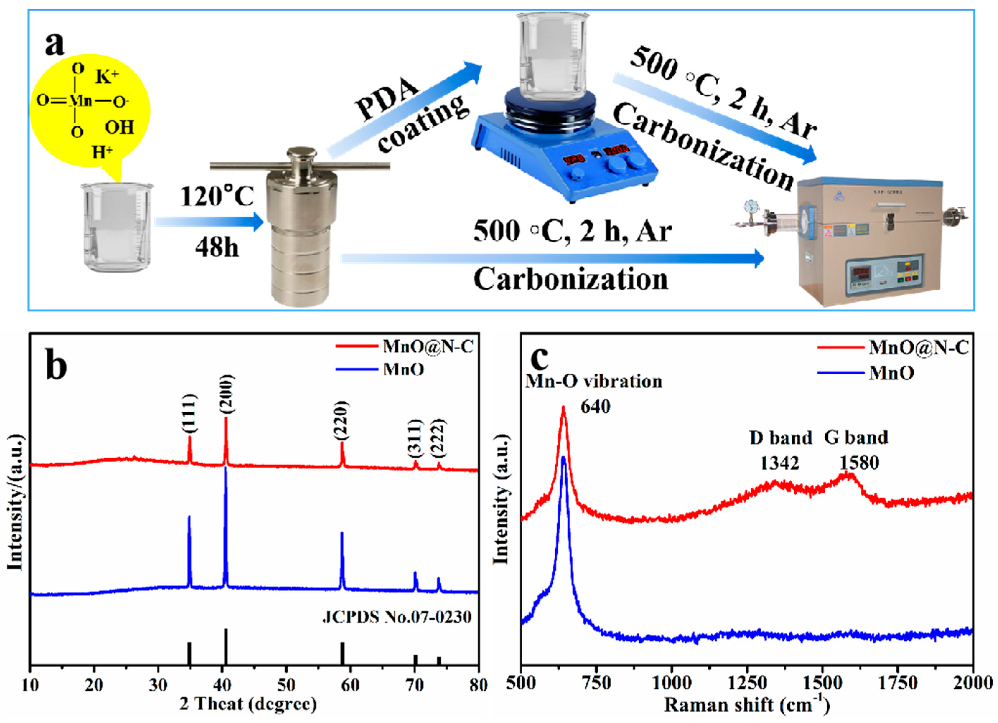
2.1. The Synthesis of MnO@N-C Composites with Ground-Moss Morphology

All chemicals utilized in the study were of analytical quality and were directly applied as received, without additional purification. The ground-moss-shaped MnO@N-C composite was prepared through a hydrothermal process, room-temperature microemulsion, and polymerization followed by calcination.
Typically, 0.65 g KMnO4 was mixed into 8 mL water. The mixture was agitated persistently at ambient temperature until fully dissolved. The uniform mixture was transferred to a 25 mL autoclave with a Teflon lining, and subsequently subjected to a temperature of 180 °C in an oven for a duration of 48 h. After returning to room temperature, the resulting precipitates were separated and rinsed through centrifugation with distilled water and ethanol. These were then desiccated at 60 °C over 6 h to yield K0.27MnO2·0.54H2O.
The MnO@N-C composite was prepared by annealing K0.5Mn2O4·1.5H2O coated with polydopamine in Ar atmosphere. Briefly, 0.1 g K0.5Mn2O4·1.5H2O was dissolved in 100 mL of 10 mM tris-buffer solution under magnetic stirring until a uniform solution was formed. Next, 50 mg of dopamine hydrochloride was introduced into the homogenous mixture, and it was continuously stirred for 16 h at room temperature. The precipitate was gathered using centrifugation and then rinsed three times with deionized water and ethanol. The as-prepared samples were calcinated at 500 °C for 2 h in Ar atmosphere with a heating rate of 5 °C min−1. After the process, we retrieved the MnO@N-C composite.
As a comparative measure, MnO nanoparticles were synthesized without incorporating polydopamine (PDA).

2.2. Materials Characterization

The sample’s morphology was examined using scanning electron microscopy (SEM, Thermo Fisher, Helios CX, Waltham, MA, USA) and further analyzed with high-resolution transmission electron microscopy (HRTEM, Thermo Fisher, Talos F200x, Waltham, MA, USA). The composition mapping was analyzed using a high-angle annular dark-field-energy-dispersive X-ray spectroscopy (HAADF-EDX) detector on the transmission electron microscope. The crystalline structures and phase were determined by X-ray diffraction (XRD, Rigaku Smartlab 9, Tokyo, Japan) using a rate of 20° min−1 with Cu Kα Karadiation (λ = 1.54 Å). We probed the surface chemistry of the MnO@N-C composite by utilizing a Raman spectroscope (Invia Microscope, Renishaw, Wotton-under-Edge, Gloucestershire, UK) set at a 532 nm laser wavelength. In tandem, we used X-ray photoelectron spectroscopy (XPS, Thermo Fischer, ESCALAB 250 instrument, Waltham, MA, USA), calibrating to the C 1s peak at 284.80 eV.

2.3. Electrochemical Measurements

The electrochemical behaviors of the MnO@N-C composite and MnO electrodes were evaluated using CR2032 coin cells, with lithium foils (14 mm in diameter) serving as the counter electrode. The working electrodes were fabricated using a uniform slurry that combined the active materials (MnO@N-C composite or MnO), carbon black (Super P), and the binder (sodium carboxymethyl cellulose, CMC) in a weight ratio of 70:20:10 [29]. The resultant slurry was pressed onto a neat current collector (copper foil) by a spreader and then dried at 70 °C for 12 h in a vacuum oven. The mass loading on the copper foil (disc diameter of 12 mm) was around 1.0 mg. The electrolyte comprised 1 M LiPF6 dissolved in a solvent blend of ethylene carbonate (EC) and diethyl carbonate (DEC) in a 1:1 volume ratio, supplemented with 5 wt% fluoroethylene carbonate (FEC). FEC is currently the most commonly used electrolyte additive. It facilitates the formation of an SEI film on the electrode surfaces, allowing for the free ingress and egress of Li+ while hindering the passage of solvent molecules. This preserves the stability of the electrode materials, enhancing both the capacity and cyclic performance of the battery. Therefore, due to its advantages in forming and stabilizing the SEI layer, FEC is not only applied with Si anodes but also extensively used in other electrode materials [30,31,32]. A Celgard 2400 membrane, with a diameter of 19 mm, served as the separator. Electrochemical performance was evaluated using a LAND CT2001A system with a voltage window of 0.01–3.0 V against Li+/Li. Both cyclic voltammetry (CV) spanning 0.01–3.0 V and electrochemical impedance spectroscopy (EIS) ranging from 100 kHz to 0.1 Hz were carried out using a Gamry electrochemical workstation.

3. Results

3.1. Composition and Microstructures of the Composite Materials

Figure 1a illustrates the overall preparation route for the MnO@N-C composite and MnO. KMnO4 and H2O were thoroughly mixed to obtain a uniform solution, followed by a hydrothermal reaction. Here, no surfactant was introduced. The phase structure was investigated by X-ray powder diffraction (XRD) (Figure S1, Supporting Information). The XRD patterns (Figure S1a) clearly indicate the presence of characteristic peaks corresponding to the compound K0.27MnO2·0.54H2O (JCPDS no. 52-0556), confirming its formation. The peaks of the XRD patterns (Figure S1b) confirm the formation of K0.5Mn2O4·1.5H2O@MnO2 (JCPDS no. 42-1317 and JCPDS no. 44-0141) after the hydrothermal reaction and after coprecipitation at room temperature.
After the calcination treatment, all the XRD peaks at 35.0°, 40.6°, 58.7°, 70.2°, and 73.8° can be perfectly matched with the standard planes for cubic MnO (JCPDS card no. 07-0230), without impurity phases (Figure 1b). Note that, when comparing the diffraction peaks of MnO and MnO@N-C, the peaks of MnO@N-C are much weaker than those of MnO (XRD patterns), demonstrating the successful loading of external carbon on the MnO samples [18,19]. The average crystallite sizes of the MnO and MnO@N-C samples calculated from the XRD data using the Scherrer equation (Equation (1)) are 44.2 and 66.7 nm, respectively.
D = K λ β cos θ
  • D: crystallite size (nm)
  • K: Scherrer constant (0.94)
  • λ: wavelength of X-ray sources (0.15406 nm)
  • β: full width at half maximum (FWHM, radians)
  • θ: peak position (radians)
The FWHM and peak positions were obtained from the XRD data using Origin and MS Excel.
At the same time, we used Bragg’s Equation (2) to calculate lattice d-spacing from the XRD data. The values for the crystallite sizes, d-spacings, and relevant data are shown in Table S1.
d = n λ 2 sin θ
  • d: interplanar spacing (nm)
  • n: order of diffraction (1)
  • λ and θ are the same as in Equation (1).
The d-spacing values for MnO@N-C are 0.268742063, 0.236723122, and 0.180206658 nm, corresponding to the (110), (200), and (220) lattice planes of the MnO phase, respectively, as per JCPDS card no. 07-0230.
Figure 1c shows the Raman spectra of both the MnO and the MnO@N-C samples. In the Raman spectra of both samples, a distinct peak is observed at 640 cm−1. This peak can be attributed to the symmetric stretching vibrations of the Mn-O bond in MnO, consistent with reports in the literature [25,33,34,35]. Thus, Raman analysis confirms the existence of amorphous carbon and graphited carbon in the MnO@N-C sample. The Raman shift at 1342 cm−1, commonly identified as the D band, signifies the vibrational modes of amorphous carbon. Notably, this carbon can enhance the diffusion of Li+ ions, provide additional active sites for lithium storage, and ensure structural stability during the lithiation/delithiation cycles [21,23,36]. Conversely, graphitic carbon’s vibrational pattern is evident at 1580 cm−1, widely recognized as the G band. Because of its sp2 bonding, this form of graphitized carbon contributes to enhancing the composite’s electrical conductivity [33,37].
In the SEM images in Figure 2a,b, it can be seen that the K0.27MnO2·0.54H2O synthesized by the solvothermal reaction shows beautiful ground-moss-shaped structures. After PDA coating as shown in Figure 2c,d, this structure is intact, except for an extra layer on the surface. The obtained MnO@N-C has the morphology of MnO nanoparticles encased in N-doped C nanosheets (Figure 2e,f). The structure of MnO (Figure 2g,h), however, consists of agglomerated small particles without the protection of PDA, which has a great volume expansion effect during charging and discharging [38,39]. The MnO@N-C sample contains C, N, O, and Mn elements (Figure S2, Supporting Information). The atomic percentage of Mn and O elements is close to 1:1, and the atomic percentage of the N element is about 1.28%.
From Figure 3a and enlarged Figure 3b, it is evident that the MnO@N-C samples are assembled from uniformly distributed MnO nanoparticles (with diameters ranging from ten to tens of nanometers) and N-doped C nanosheets. The structure of the N-doped C nanosheets prevents MnO nanoparticle aggregation, promoting the electrochemical reaction of MnO nanoparticles. Moreover, the lattice fringes can also be clearly observed (inset of Figure 3b). The interlayer spacing of 0.22 nm commendably fits to the (200) lattice planes of MnO (JCPDS card no. 07-0230). The information in Figure 3c, utilizing HAADF-STEM, where STEM is scanning transmission electron microscopy, and EDX, confirms the even distribution of Mn, O, C, and N elements in MnO@N-C.
Using X-ray photoelectron spectroscopy (XPS), the chemical composition and elemental valence states of MnO@N-C were identified. The XPS survey spectrum (Figure 4a) clearly shows that Mn, C, N, and O coexist in the MnO@N-C sample. In the C 1s high-resolution spectrum shown in Figure 4b, the four peaks at 284.5 eV, 285.2 eV, 286.2 eV and 288.6 eV should be associated with the sp2 bonds of C=C bonds, sp2-hybridized graphitic carbon of C−C bonds, and sp3 bonds of C−N and C−O, usually located at the defect sites, respectively. Additionally, these findings indicate that N has been seamlessly integrated into the carbon layer, potentially enhancing the material interface for improved performance [19,40]. The N 1s high-resolution spectrum, as shown in Figure 4c, displays a fitting into four distinct peaks at binding energies of 398.2 eV, 399.6 eV, 400.3 eV, and 401.1 eV. These peaks correspond to pyridinic N, N−Mn bonds, connections, pyrrolic N, and graphitic N, respectively [19,26,41,42,43]. In the fitted Mn 2p high-resolution spectrum displayed in Figure 4d, the two main peaks at 640.9 eV and 652.8 eV could correspond to Mn2+. These results confirm the formation of MnO [44,45].

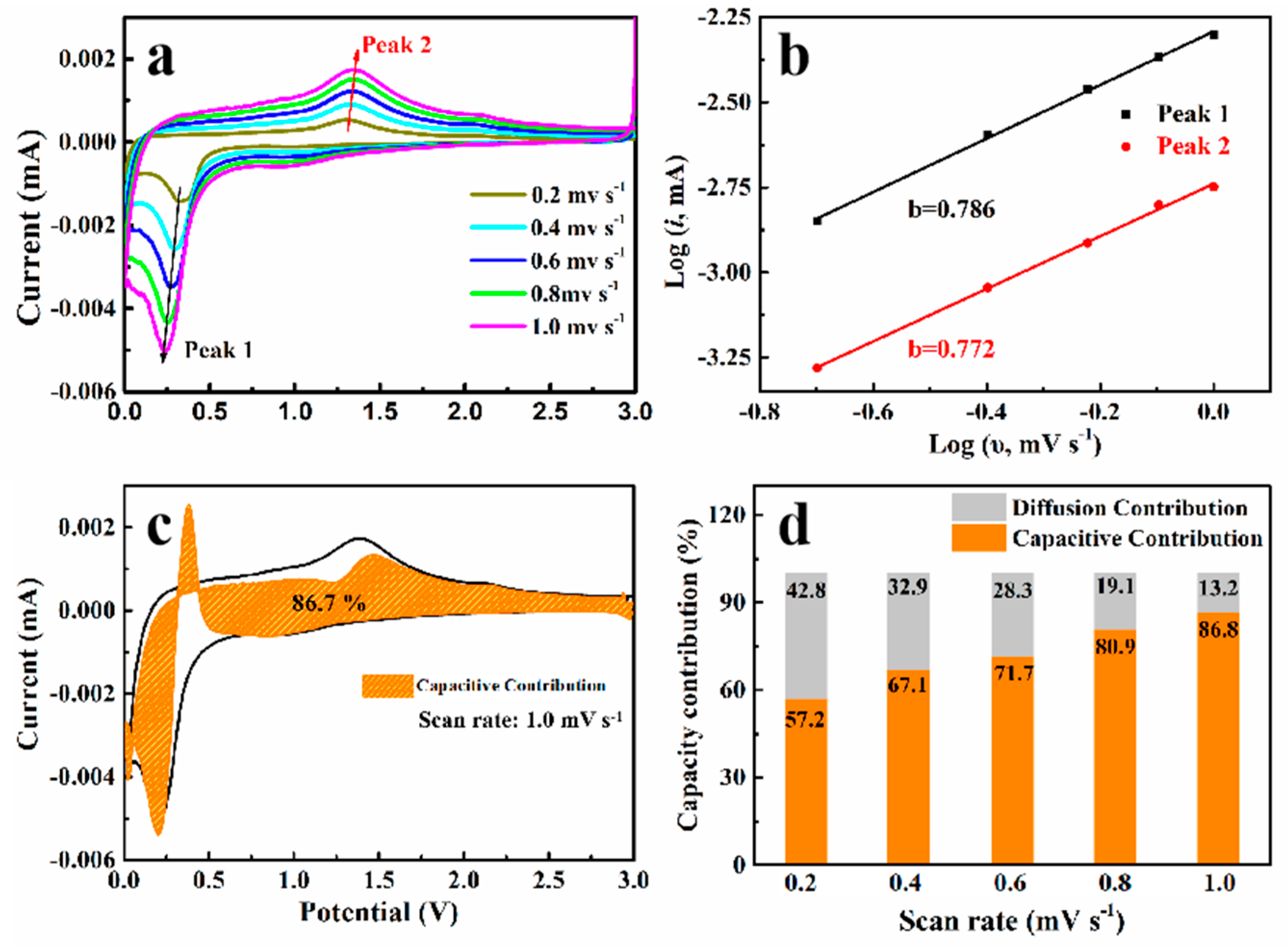
3.2. Electrochemical Properties in Half-Cells

The electrochemical behavior of MnO@N-C and MnO electrodes when used as anode materials in Li+ half-cells was comprehensively studied. To understand the electrochemical reaction mechanism, cyclic voltammetry (CV) measurements of the MnO/N-C electrode in the initial five cycles were conducted. As shown in Figure 5a, in the first scan of CV curves, the cathodic peaks located at 0.01 and 0.13 V are related to Mn2+ in MnO and to metallic Mn0, on the basis of the reaction MnO + 2Li+ + 2e → Mn + Li2O [23,46]. The peak observed at 0.83 V relates to an irreversible electrolyte reduction culminating in the establishment of an SEI film. Meanwhile, the broad anodic peak at 1.28 V is attributed to the conversion of Mn0 into Mn2+, as represented by the reaction Mn + Li2O → MnO + 2e+ + 2Li+. There is another weak anodic peak at 2.06 V, which is attributed to the further oxidation of Mn2+ to a higher valence, thereby providing extra capacity. Meanwhile, the broad anodic peak at 1.28 V is attributed to the conversion of Mn0 into Mn2+, as represented by the reaction Mn + Li2O → MnO + 2e+ + 2Li+. There is another weak anodic peak at 2.06 V, which is attributed to the further oxidation of Mn2+ to a higher valence, thereby providing extra capacity [22,47]. In subsequent CV profiles, the cathodic peaks shift to about 0.43 V, but the anodic peak is still at about 1.28 V. The CV profiles post the initial cycle closely coincide with one another, indicating that the MnO/N-C sample possesses outstanding structural integrity.
Figure 5b showcases the first five galvanostatic charge/discharge profiles of MnO@N-C, recorded at 100 mA g−1 within a voltage window of 0.01–3 V relative to Li+/Li. The initial specific capacities for discharge and charge are 1120 mAh g−1 and 808 mAh g−1, respectively. Notably, MnO@N-C exhibits a higher initial Coulombic efficiency (CE) of 72.1% compared to MnO, which stands at approximately 54%. This might be attributed to the combined effect of nanosized MnO particles and the N-C framework. Together, they can effectively host extra lithium ions at the surface and enhance the reversibility of the electrochemical process [24,48]. In the following cycles, the MnO@N-C electrode demonstrates consistent cycling behavior, maintaining a Coulombic efficiency (CE) exceeding 95.0%.
For comparison, the galvanostatic discharge–charge performances of MnO@N-C and MnO electrodes are displayed in Figure 5c. During cycling, the MnO@N-C electrode displays a greater reversible capacity compared to MnO. Specifically, after 70 cycles, the capacities stabilize at 808 mAh g−1 for MnO@N-C and 280 mAh g−1 for MnO, respectively. Compared to MnO, the MnO@N-C sample possesses a reduced primary particle size and accelerated reaction kinetics. This facilitates the oxidation of Mn2+ to an elevated valence state, which is reflected by the subdued anodic peak at 2.06 V in the CV profiles. No similar anodic peak can be observed in the CV curves of MnO (Figure S3, Supporting Information). Thus, the MnO@N-C sample yielded a higher capacity [18]. In this test, the MnO@N-C and MnO electrodes show initial CE values of 73.2% and 53.5%, respectively (Figure 5d). During the first discharge/charge cycle, there was a noticeable decrease in capacity. This was mainly due to the breakdown of the electrolyte and the resulting formation of an SEI layer on the surface of the active substances [21,47]. This implies that when this material is used in a full LIBs, it will deplete the cathode of its lithium ions and assist in recovering the lithium-ion losses during SEI formation. Consequently, this approach offers opportunities for the practical application of MnO@N-C [49].
As depicted in Figure 5e, comparing the rate characteristics of the MnO@N-C and MnO electrodes at current densities of 100, 200, 500, 1000, and 2000 mA g−1, the MnO@N-C electrode yields impressive reversible specific capacities of 840, 820, 730, 640, and 590 mAh g−1, respectively. Specific capacity decreases gradually as current density increases step by step, implying that the electrochemical reaction of the electrode is a diffusion-controlled kinetics reaction [46,50]. When the current density is reduced to 100 mA g−1, the specific capacity can be recovered to 910 mA h g−1. These results are far better than those for the MnO (320, 260, 210, 170, 140, and 320 mA h g−1 at current densities of 100, 200, 500, 1000, 2000 and 100 mA g−1, respectively). Evidently, the MnO@N-C electrode exhibits much higher Li-ion storage performance compared with MnO, which lacks a carbon coating on the electrode. As expected, the MnO@N-C electrode also shows an excellent long-term cycling performance at the high current density of 1000 mA g−1. As the number of cycles increases, the specific capacities of the MnO@N-C and the MnO electrodes slowly fluctuate up and down, ultimately maintaining 560 and 286 mAh g−1 after 300 cycles, respectively.
To quantify the electrochemical reaction kinetics of Li+ storage in the MnO@N-C electrode, the CV curves were tested at stepwise scan rates within the range of 0.01–3.0 V. As is conveyed by Figure 6a, these curves display obvious cathodic/anodic peaks that have similar shapes to the accordingly increasing values of peak current when the scan rate increases. Therefore, the charge storage mechanism of the MnO@N-C electrode consists of both capacitive and diffusion behavior. According to power law, the relationship between the scan rate (v) and peak current (i) is described by the following Equations (3) and (4) [19,20,24,48]:
i = a × υb
Log (i) = b × log (υ) + log (a)
When the value of b approximates 0.5, the charge storage mechanism is based on the diffusion-controlled component. If the b-value is close to 1, it indicates the capacitive charge storage behaviors. The b-value comes from the log (i) vs. log (v) plots (Figure 6b). The b values for peak 1 and peak 2 of the MnO@N-C electrode were calculated to be 0.786 and 0.772, respectively. This can well explain its high capacitive charge storage behavior and superior rate performance. The proportion of the pseudocapacitive contribution can be quantitatively calculated through Equation (5), where the current (i) corresponds to a given potential and scan rate (v):
i(V) = k1 × v + k2 × v1/2
where k1 × v signifies the capacitive contribution, whereas k2 × v1/2 indicates the diffusion-related contribution [51,52].
As inferred from the fitting in Figure 6c, the capacitive contribution (highlighted in orange) accounts for 86.7% of the total current at a scan rate of 1.0 mV s−1 [52]. As shown in Figure 6d, with an increase in the scan rate, there is a notable increase in the capacitive contribution. This highlights the outstanding rate capability of the MnO@N-C electrode. This phenomenon can be attributed to the combined influences of both the capacitance-controlled and diffusion-controlled contributions, which aid in advancing the redox reactions. Additionally, the presence of ultrafine nanocrystals encapsulated within the carbon shell ensures enhanced stability.
Electrochemical impedance spectroscopy (EIS) measurements were conducted on a fresh battery and after 50 cycles at 1 A g−1. They were measured over a frequency range from 100 kHz to 0.01 Hz to investigate the electrochemical resistance of the MnO@N-C and MnO electrodes. The Nyquist plots predominantly feature a semicircle in the high-frequency domain, symbolizing charge transfer resistance (Rct) at the interface between the material and the electrolyte. In contrast, the sloping line in the low-frequency range indicates the migration resistance (Zw) of the Li-ion within the electrolyte. A fit of the Nyquist plots was conducted using an equivalent circuit model (Figure S4, Supporting Information) [49]. Based on the fitted parameters (Table S2, Supporting Information), it was observed that MnO@N-C has reduced Rct value compared to MnO, a characteristic aligning well with its heightened electrochemical performance [19,39,53]. To assess their structural stability, SEM characterization was carried out on cross-sections of the MnO and MnO@N-C electrodes, both in their fresh state and after undergoing 50 cycles at 1 A g−1. As highlighted in Figure S5, the expansion rate for MnO was found to be 127.8%, whereas MnO@N-C recorded a rate of 115.5%. At the same time, it could be observed that a slurry mixture with a sponge-like structure on a Cu substrate could buffer volume changes and promote electrolyte penetration, leading to superior electrochemical performance [20,54]. Moreover, the parameter comparison of the MnO@N-C electrode compared to other MnO and N-doped C anodes (Table S3, Supporting Information). From the table, it can be observed that the 3D ground-moss-shaped MnO@N-C composite prepared in this study had a relatively high initial CE. This provides an opportunity for the practical application of manganese-based materials.

4. Conclusions

Using a surfactant-free hydrothermal method, followed by PDA coating and calcination treatment, we adeptly produced a 3D ground-moss-shaped MnO@N-C composite comprising MnO nanoparticles encapsulated in N-doped carbon shells. The highly conductive N-doped carbon effectively reduced the ion/electron transport distance. Additionally, the 3D structures mitigated volume changes and promoted efficient electron transport. After 300 cycles at 1 A g−1, the MnO@N-C electrode exhibited a commendable capacity of 560 mAh g−1 and an impressive initial Coulombic efficiency (CE) of approximately 72%. The commendable Li+ storage performance coupled with its efficient fabrication process suggests that the MnO@N-C composite holds significant potential as a leading anode material for next-generation LIBs.

Supplementary Materials

The following supporting information can be downloaded at: https://www.mdpi.com/article/10.3390/cryst13101420/s1, Figure S1: XRD patterns for precursors (a) after hydrothermal reaction and (b) after coprecipitation at room temperature. Figure S2: (a,b) EDX spectrum from SEM image of MnO@N-C. (Table inset i is the chemical composition of MnO@N-C.) Figure S3: CV curves of MnO electrode at 0.1 mV s−1. Figure S4: Nyquist plots of the MnO@N-C and MnO electrodes before cycling. Inset is the corresponding equivalent circuit. Figure S5: (a) SEM cross section of anode of Cu substrate before and after 50 cycles at 1 A g−1: (a,c) MnO; (b,d) MnO@N-C. Table S1: Peak cent, FWHM, crystallite sizes and d-spacing are obtained from XRD data. Table S2: Rs and Rct based on the EIS fitting outcomes of MnO@N-C and MnO. Table S3. Comparison of lithium storage performance between MnO@N-C and other reported MnO and N-doped C based electrodes. Reference [55] is cited in the supplementary materials.

Author Contributions

Conceptualization and methodology, Y.Z., S.Z. and K.Q.; validation, L.G., Y.G., W.W. and H.C.; formal analysis, Y.Z. and Z.T.; investigation, L.G., Y.G., W.W. and H.C.; writing—original draft preparation, Y.Z.; writing—review and editing, Z.B. and N.W.; visualization, Z.B.; supervision, Y.Z., G.T. and Z.B.; project administration, Z.T. All authors have read and agreed to the published version of the manuscript.

Funding

This research was funded by the Research Fund for the Doctoral Program of Liaocheng University, grant number 318051638; the Development Project of the Youth Innovation Team in Shandong Colleges and Universities, grant number 2019KJC031; the Science and Technology Innovation Foundation for the University or College Students, grant number CXCY2023088; the SMES Innovation Ability Improvement Project of Shandong Province Science and Technology, grant number 2022TSGC1370.

Data Availability Statement

The data presented in this study are available on request from the corresponding author.

Acknowledgments

The authors thank Tania Silver for her helpful discussions.

Conflicts of Interest

The authors declare no conflict of interest.

References

  1. Xue, P.; Zhai, Y.; Wang, N.; Zhang, Y.; Dou, S. Selenium@Hollow Mesoporous Carbon Composites for High-Rate and Long-Cycling Lithium/Sodium-Ion Batteries. Chem. Eng. J. 2019, 392, 123676. [Google Scholar] [CrossRef]
  2. Yang, Y.; Okonkwo, E.G.; Huang, G.; Xu, S.; He, Y. On the sustainability of lithium ion battery industry—A review and perspective. Energy Storage Mater. 2020, 36, 186–212. [Google Scholar] [CrossRef]
  3. Wang, Y.; Zhang, X.; Li, K.; Zhao, G.; Chen, Z. Perspectives and challenges for future lithium-ion battery control and management. eTransportation 2023, 18, 100260. [Google Scholar] [CrossRef]
  4. Chen, X.; Zhang, Z.; Xu, R.; Gao, X.; Zhou, D.; Yuan, T.; Chen, Y.; Cui, L. In-situ embedding of ultrasmall MnO nanoparticles into pollen biomass-derived hollow porous N heteroatoms enriched carbon microspheres as high-performance anode for lithium-ion batteries. Chem. Eng. J. 2023, 473, 145117. [Google Scholar] [CrossRef]
  5. Wang, M.; Bai, Z.; Yang, T.; Nie, C.; Xu, X.; Wang, Y.; Yang, J.; Dou, S.; Wang, N. Advances in high sulfur loading cathodes for practical lithium-sulfur batteries. Adv. Energy Mater. 2022, 12, 2201585. [Google Scholar] [CrossRef]
  6. Yang, Y.; Dong, R.; Cheng, H.; Wang, L.; Tu, J.; Zhang, S.; Zhao, S.; Zhang, B.; Pan, H.; Lu, Y. 2D Layered Materials for Fast-Charging Lithium-Ion Battery Anodes. Small 2023, 19, 2301574. [Google Scholar] [CrossRef] [PubMed]
  7. Xiao, J.; Li, Q.; Bi, Y.; Cai, M.; Dunn, B.; Glossmann, T.; Liu, J.; Osaka, T.; Sugiura, R.; Wu, B. Understanding and applying coulombic efficiency in lithium metal batteries. Nat. Energy 2020, 5, 561–568. [Google Scholar] [CrossRef]
  8. Zhang, S.; Xu, Y.; Cheng, X.; Gao, S.; Zhang, X.; Zhao, H.; Huo, L. Compounds, Coordination polymer-derived hierarchically structured MnO/NC composites as anode materials for high-performance lithium-ion batteries. J. Alloys Compd. 2023, 941, 168847. [Google Scholar] [CrossRef]
  9. Nzereogu, P.; Omah, A.; Ezema, F.; Iwuoha, E.; Nwanya, A. Anode materials for lithium-ion batteries: A review. Appl. Surf. Sci. Adv. 2022, 9, 100233. [Google Scholar] [CrossRef]
  10. Baboukani, A.R.; Khakpour, I.; Adelowo, E.; Drozd, V.; Shang, W.; Wang, C. High-performance red phosphorus-sulfurized polyacrylonitrile composite by electrostatic spray deposition for lithium-ion batteries. Electrochim. Acta 2020, 345, 136227. [Google Scholar] [CrossRef]
  11. Parekh, M.H.; Sediako, A.D.; Naseri, A.; Thomson, M.J.; Pol, V. In Situ Mechanistic Elucidation of Superior Si-C-Graphite Li-Ion Battery Anode Formation with Thermal Safety Aspects. Adv. Energy Mater. 2020, 10, 1902799. [Google Scholar] [CrossRef]
  12. Sarang, K.T.; Li, X.; Miranda, A.; Terlier, T.; Oh, E.-S.; Verduzco, R.; Lutkenhaus, J. Tannic acid as a small-molecule binder for silicon anodes. ACS Appl. Energy Mater. 2020, 3, 6985–6994. [Google Scholar] [CrossRef]
  13. Li, J.; Fleetwood, J.; Hawley, W.B.; Kays, W. From materials to cell: State-of-the-art and prospective technologies for lithium-ion battery electrode processing. Chem. Rev. 2021, 122, 903–956. [Google Scholar] [CrossRef]
  14. Chen, Y.; Chen, X.; Zhang, Y. Fuels, A comprehensive review on metal-oxide nanocomposites for high-performance lithium-ion battery anodes. J. Energy Fuels 2021, 35, 6420–6442. [Google Scholar] [CrossRef]
  15. Hua, X.; Allan, P.K.; Gong, C.; Chater, P.A.; Schmidt, E.M.; Geddes, H.S.; Robertson, A.W.; Bruce, P.G.; Goodwin, A. Non-equilibrium metal oxides via reconversion chemistry in lithium-ion batteries. Nat. Commun. 2021, 12, 561. [Google Scholar] [CrossRef]
  16. Sheng, L.; Liang, S.; Wei, T.; Chang, J.; Jiang, Z.; Zhang, L.; Zhou, Q.; Zhou, J.; Jiang, L.; Fan, Z. Space-confinement of MnO nanosheets in densely stacked graphene: Ultra-high volumetric capacity and rate performance for lithium-ion batteries. Energy Storage Mater. 2018, 12, 94–102. [Google Scholar] [CrossRef]
  17. Yang, S.; Zou, Z.; Jiang, C. A ternary MnO/MnTiO3@C composite anode with greatly enhanced cycle stability for Li-ion batteries. Ceram. Int. 2023, 49, 8112–8120. [Google Scholar] [CrossRef]
  18. Hong, Y.; Hu, Q.; Dong, H.; Li, J.; Tang, Z.; Wang, X.; Ouyang, J.; Liu, T. N-doped carbon coated porous hierarchical MnO microspheres as superior additive-free anode materials for lithium-ion batteries. Scr. Mater. 2022, 211, 114495. [Google Scholar] [CrossRef]
  19. Sun, Z.; Liu, C.; Shi, J.; Huang, M.; Liu, S.; Shi, Z.; Wang, H. Compounds, One-pot synthesis of nanosized MnO incorporated into N-doped carbon nanosheets for high performance lithium storage. J. Alloys Compd. 2022, 902, 163827. [Google Scholar] [CrossRef]
  20. He, C.; Li, J.; Zhao, X.; Peng, X.; Lin, X.; Ke, Y.; Xiao, X.; Zuo, X.; Nan, J. In situ anchoring of MnO nanoparticles into three-dimensional nitrogen-doped porous carbon framework as a stable anode for high-performance lithium storage. Appl. Surf. Sci. 2023, 614, 156217. [Google Scholar] [CrossRef]
  21. Gan, Q.; He, H.; Zhao, K.; He, Z.; Liu, S. Preparation of N-doped porous carbon coated MnO nanospheres through solvent-free in-situ growth of ZIF-8 on ZnMn2O4 for high-performance lithium-ion battery anodes. Electrochim. Acta 2018, 266, 254–262. [Google Scholar] [CrossRef]
  22. Liu, Y.; Sun, S.; Han, J.; Gao, C.; Fan, L.; Guo, R. Multi-yolk–shell MnO@carbon nanopomegranates with internal buffer space as a lithium ion battery anode. Langmuir 2021, 37, 2195–2204. [Google Scholar] [CrossRef]
  23. Chen, F.; Liu, Z.; Yu, N.; Sun, H.; Geng, B. Constructing an interspace in MnO@ NC microspheres for superior lithium ion battery anodes. Chem. Commun. 2021, 57, 10951–10954. [Google Scholar] [CrossRef] [PubMed]
  24. Liu, R.; Zhao, X.; Liang, L.; Li, R.; Fan, P.; Li, J.; Zhao, H. Compounds, Double-network aerogel-derived spongy 3D porous MnO/C composite for lithium-ion batteries with increasing capacity. J. Alloys Compd. 2023, 948, 169799. [Google Scholar] [CrossRef]
  25. Huang, S.; Li, H.; Xu, G.; Liu, X.; Zhang, Q.; Yang, L.; Cao, J.; Wei, X. Porous N-doped carbon sheets wrapped MnO in 3D carbon networks as high-performance anode for Li-ion batteries. Electrochim. Acta 2020, 342, 136115. [Google Scholar] [CrossRef]
  26. Wang, N.; Zhang, X.; Ju, Z.; Yu, X.; Wang, Y.; Du, Y.; Bai, Z.; Dou, S.; Yu, G. Thickness-independent scalable high-performance Li-S batteries with high areal sulfur loading via electron-enriched carbon framework. Nat. Commun. 2021, 12, 4519. [Google Scholar] [CrossRef] [PubMed]
  27. Liu, J.; You, F.; He, B.; Wu, Y.; Wang, D.; Zhou, W.; Qian, C.; Yang, G.; Liu, G.; Wang, H. Directing the architecture of surface-clean Cu2O for CO electroreduction. J. Am. Chem. Soc. 2022, 144, 12410–12420. [Google Scholar] [CrossRef] [PubMed]
  28. Hu, Q.; Wang, B.; Chang, S.; Yang, C.; Hu, Y.; Cao, S.; Lu, J.; Zhang, L.; Ye, H. Technology, Effects of annealing temperature on electrochemical performance of SnSx embedded in hierarchical porous carbon with N-carbon coating by in-situ structural phase transformation as anodes for lithium ion batteries. J. Mater. Sci. Technol. 2021, 84, 191–199. [Google Scholar] [CrossRef]
  29. Ko, I.-H.; Jin, A.; Kim, M.K.; Park, J.-H.; Kim, H.S.; Yu, S.-H.; Sung, Y.-E. Compounds, The keys for effective distribution of intergranular voids of peapod-like MnO@C core-shell for lithium ion batteries. J. Alloys Compd. 2020, 817, 152760. [Google Scholar] [CrossRef]
  30. Kitz, P.G.; Lacey, M.J.; Novák, P.; Berg, E. Operando investigation of the solid electrolyte interphase mechanical and transport properties formed from vinylene carbonate and fluoroethylene carbonate. J. Power Sources 2020, 477, 228567. [Google Scholar] [CrossRef]
  31. Markevich, E.; Salitra, G.; Aurbach, D. Fluoroethylene carbonate as an important component for the formation of an effective solid electrolyte interphase on anodes and cathodes for advanced Li-ion batteries. ACS Energy Lett. 2017, 2, 1337–1345. [Google Scholar] [CrossRef]
  32. Jiao, R.; Zhao, L.; Zhou, S.; Zhai, Y.; Wei, D.; Zeng, S.; Zhang, X.J.N. Effects of carbon content and current density on the Li+ storage performance for MnO@C nanocomposite derived from Mn-based complexes. Nanomaterials 2020, 10, 1629. [Google Scholar] [CrossRef]
  33. Wang, S.; Dong, Y.; Cao, F.; Li, Y.; Zhang, Z.; Tang, Z.J. Conversion-Type MnO Nanorods as a Surprisingly Stable Anode Framework for Sodium-Ion Batteries. Adv. Funct. Mater. 2020, 30, 2001026. [Google Scholar] [CrossRef]
  34. Sheng, L.; Jiang, H.; Liu, S.; Chen, M.; Wei, T.; Fan, Z. Nitrogen-doped carbon-coated MnO nanoparticles anchored on interconnected graphene ribbons for high-performance lithium-ion batteries. J. Power Sources 2018, 397, 325–333. [Google Scholar] [CrossRef]
  35. Zou, Y.; Guo, Z.; Ye, L.; Cui, Y.; Zheng, K.; Zhao, L. Raspberry-shaped nickel-enhanced MnO-based carbon-containing nanostructures as anode materials for Li-ion batteries. ACS Appl. Nano Mater. 2021, 4, 7925–7934. [Google Scholar] [CrossRef]
  36. Xing, Z.; Ju, Z.; Zhao, Y.; Wan, J.; Zhu, Y.; Qiang, Y.; Qian, Y. One-pot hydrothermal synthesis of Nitrogen-doped graphene as high-performance anode materials for lithium ion batteries. Sci. Rep. 2016, 6, 26146. [Google Scholar] [CrossRef]
  37. Lee, J.S.; Park, J.-S.; Baek, K.W.; Saroha, R.; Yang, S.H.; Kang, Y.C.; Cho, J. Coral-like porous microspheres comprising polydopamine-derived N-doped C-coated MoSe2 nanosheets composited with graphitic carbon as anodes for high-rate sodium-and potassium-ion batteries. Chem. Eng. J. 2023, 456, 141118. [Google Scholar] [CrossRef]
  38. Jia, J.; Hu, X.; Wen, Z. Robust 3D network architectures of MnO nanoparticles bridged by ultrathin graphitic carbon for high-performance lithium-ion battery anodes. Nano Res. 2018, 11, 1135–1145. [Google Scholar] [CrossRef]
  39. Lin, J.; Yu, L.; Sun, Q.; Wang, F.; Cheng, Y.; Wang, S.; Zhang, X. Multiporous core-shell structured MnO@N-Doped carbon towards high-performance lithium-ion batteries. Int. J. Hydrogen Energy 2020, 45, 1837–1845. [Google Scholar] [CrossRef]
  40. Xiao, T.; Zhang, W.; Xu, T.; Wu, J.; Wei, M.J.E.A. Hollow SiO2 microspheres coated with nitrogen doped carbon layer as an anode for high performance lithium-ion batteries. Electrochim. Acta 2019, 306, 106–112. [Google Scholar] [CrossRef]
  41. Pei, X.-Y.; Mo, D.-C.; Lyu, S.-S.; Zhang, J.-H.; Fu, Y.-X. Facile preparation of N-doped MnO/rGO composite as an anode material for high-performance lithium-ion batteries. Appl. Surf. Sci. 2019, 465, 470–477. [Google Scholar] [CrossRef]
  42. Li, X.; Wang, H.; Zhang, W.; Wei, W.; Liao, R.; Shi, J.; Huang, M.; Liu, S.; Shi, Z. High potassium ion storage capacity with long cycling stability of sustainable oxygen-rich carbon nanosheets. Nanoscale 2021, 13, 2389–2398. [Google Scholar] [CrossRef]
  43. Zhang, K.; Han, P.; Gu, L.; Zhang, L.; Liu, Z.; Kong, Q.; Zhang, C.; Dong, S.; Zhang, Z.; Yao, J. Synthesis of nitrogen-doped MnO/graphene nanosheets hybrid material for lithium ion batteries. ACS Appl. Mater. 2012, 4, 658–664. [Google Scholar] [CrossRef] [PubMed]
  44. Meng, T.; Mao, B.; Cao, M. In situ coupling of MnO and Co@N-doped graphite carbon derived from prussian blue analogous achieves high-performance reversible oxygen electrocatalysis for Zn–Air batteries. Inorg. Chem. 2021, 60, 10340–10349. [Google Scholar] [CrossRef]
  45. Cui, Z.; Liu, Q.; Xu, C.; Zou, R.; Zhang, J.; Zhang, W.; Guan, G.; Hu, J.; Sun, Y. A new strategy to effectively alleviate volume expansion and enhance the conductivity of hierarchical MnO@C nanocomposites for lithium ion batteries. J. Mater. Chem. A 2017, 5, 21699–21708. [Google Scholar] [CrossRef]
  46. Zhan, D.; Wen, T.; Li, Y.; Zhu, Y.; Liu, K.; Cui, P.; Jia, Z.; Liu, H.; Lei, K.; Xiao, Z. Using peanut shells to construct a porous MnO/C composite material with highly improved lithium storage performance. ChemElectroChem 2020, 7, 347–354. [Google Scholar] [CrossRef]
  47. Hu, Y.; Wu, K.; Zhang, F.; Zhou, H.; Qi, L. Hierarchical MnO@C hollow nanospheres for advanced lithium-ion battery anodes. ACS Appl. Nano Mater. 2018, 2, 429–439. [Google Scholar] [CrossRef]
  48. Lei, D.; Hou, Z.; Li, N.; Cao, Y.; Ren, L.; Liu, H.; Zhang, Y.; Wang, J.-G. A homologous N/P-codoped carbon strategy to streamline nanostructured MnO/C and carbon toward boosted lithium-ion capacitors. Carbon 2023, 201, 260–268. [Google Scholar] [CrossRef]
  49. Parekh, M.H.; Palanisamy, M.; Pol, V. Reserve lithium-ion batteries: Deciphering in situ lithiation of lithium-ion free vanadium pentoxide cathode with graphitic anode. Carbon 2023, 203, 561–570. [Google Scholar] [CrossRef]
  50. Wang, L.; Yan, J.; Xu, Z.; Wang, W.; Wen, J.; Bai, X. Rate mechanism of vanadium oxide coated tin dioxide nanowire electrode for lithium ion battery. Nano Energy 2017, 42, 294–299. [Google Scholar] [CrossRef]
  51. Gao, J.; Li, Y.; Shi, L.; Li, J.; Zhang, G. Rational design of hierarchical nanotubes through encapsulating CoSe2 nanoparticles into MoSe2/C composite shells with enhanced lithium and sodium storage performance. ACS Appl. Mater. 2018, 10, 20635–20642. [Google Scholar] [CrossRef] [PubMed]
  52. Park, G.D.; Park, J.-S.; Kim, J.K.; Kang, Y. Metal sulfoselenide solid solution embedded in porous hollow carbon nanospheres as effective anode material for potassium-ion batteries with long cycle life and enhanced rate performance. Chem. Eng. J. 2022, 428, 131051. [Google Scholar] [CrossRef]
  53. Chen, Z.; Song, J.; Zhang, B.; Wu, Z.; Mandler, D.; Lei, W.; Hao, Q. Double-carbon coated MnO nanoparticles as high-performance anode materials for lithium-ion storage. Ionics 2023, 29, 483–496. [Google Scholar] [CrossRef]
  54. Yao, Q.; Zhu, Y.; Zheng, C.; Wang, N.; Wang, D.; Tian, F.; Bai, Z.; Yang, J.; Qian, Y.; Dou, S. Intermolecular Cross-Linking Reinforces Polymer Binders for Durable Alloy-Type Anode Materials of Sodium-Ion Batteries. Adv. Energy Mater. 2023, 13, 2202939. [Google Scholar] [CrossRef]
  55. Gong, Y.; Sun, L.; Si, H.; Zhang, Y.; Shi, Y.; Wu, L.; Gu, J.; Zhang, Y. MnO nanorods coated by Co-decorated N-doped carbon as anodes for high performance lithium ion batteries. Appl. Surf. Sci. 2020, 504, 144479. [Google Scholar] [CrossRef]
Figure 1. (a) Schematic illustration of the overall synthesis process; (b) XRD patterns and (c) Raman spectra for MnO and MnO@N-C samples.
Crystals 13 01420 g001
Figure 2. SEM images of (a,b) K0.27MnO2·0.54H2O, (c,d) K0.5Mn2O4·1.5H2O@MnO2, (e,f) MnO@N-C, and (g,h) MnO.
Crystals 13 01420 g002
Figure 3. (a,b) Transmission electron microscope (TEM) images, with the inset to (b) showing its corresponding HRTEM image (inset: further magnified image of the area within the white circle); (c) HAADF-STEM image and its corresponding energy dispersive spectroscopy (EDS) elemental mapping for the MnO@N-C.
Crystals 13 01420 g003
Figure 4. (a) Survey XPS spectrum of MnO@N-C; high-resolution spectra of (b) C 1 s, (c) N 1 s, and (d) Mn 2p.
Crystals 13 01420 g004
Figure 5. (a) CV curves at 0.1 mV s−1 and (b) galvanostatic discharge–charge curves of the MnO@N-C sample at 100 mA g−1 in the first five cycles in the voltage range of 0.01−3.0 V versus Li+/Li; (c) galvanostatic discharge–charge over 70 cycles at 100 mA g−1; (d) corresponding Coulombic efficiency at 100 mA g−1; (e) rate performance and (f) long-term cycling performance of MnO@NC and MnO electrodes.
Crystals 13 01420 g005
Figure 6. (a) CV curves of MnO@N-C electrode at various scan rates (0.2, 0.4, 0.6, 0.8, 1.0 mV s−1); (b) fitted log (i, peak current) versus log (v, scan rate) for peak 1 and peak 2 in CV curves; (c) capacitive contribution (orange region) at scan rate of 1.0 mV s−1 and (d) capacity contribution and diffusion contribution at diverse scan rates of MnO@N-C electrode.
Crystals 13 01420 g006
Disclaimer/Publisher’s Note: The statements, opinions and data contained in all publications are solely those of the individual author(s) and contributor(s) and not of MDPI and/or the editor(s). MDPI and/or the editor(s) disclaim responsibility for any injury to people or property resulting from any ideas, methods, instructions or products referred to in the content.

