Abstract
Liquid crystal elastomers (LCEs) are a monolithic material with programmable three-dimensional (3D) morphing modes stemming from their designable non-uniform molecular orientations (or director). However, the shape morphing mode is generally fixed when director patterns of LCEs are determined. Multi-mode shape morphing is difficult to achieve since director patterns cannot be reconfigured. Herein, we demonstrate the ability to reconfigure LCE director patterns and initial shapes—and thus shape morphing modes—by the manual assembly and de-assembly of LCE pixels. We measured the mechanical properties of LCEs with and without UV glue and found their Young’s moduli were 9.6 MPa and 11.6 MPa. We firstly fabricate LCE pixels with designed director fields and then assemble 24 pixels with required director fields into an LCE film with a designed director pattern, which corresponds to a programmed shape morphing mode. We further exhibit that we can de-assemble the LCE film back into original pixels or new pixels with different shapes and then re-assemble them into a new film with a different initial shape and director pattern, which corresponds to a second programmed shape morphing mode. Principally, we can have a large amount of shape morphing modes if we have enough pixels. The demonstrated capability of multi-mode shape morphing enhances functions of LCEs, which broadens their applications in soft robotics, programmable origami/kirigami, responsive surfaces, and so on.
1. Introduction
Liquid crystal elastomers (LCEs) exhibit up to 400% strain [1,2] under various external stimuli, such as temperature [3], light [4], and magnetic field [5]. One advantage of LCEs, compared to other stimuli-responsive materials, is their programmable three-dimensional (3D) shape morphing from a monolithic material, which relies on the designable molecular orientations (or director) of LCEs introduced by mechanical stretching [2], magnetic field alignment [6,7,8], or surface alignment [9,10,11]. Due to their advanced shape morphing capabilities, LCEs are an ideal candidate for artificial muscles [12,13], micro-mechanical actuators [14,15,16], and micro-robots [17].
Recent research efforts are focused on LCEs with programmable 3D initial shapes and 3D director patterns, to enable more freedom in designing shape morphing modes. For example, inkjet printing can introduce 3D initial shapes of LCEs with director fields along the printing path [18,19]; photopatterned surfaces can command designable two-dimensional (2D) LCE director patterns [20,21,22]; and optical 3D printing enables 3D LCE structures with printing path-independent director fields, which are determined by either external magnetic fields [23] or commanding surfaces [10,24]. Recently, Sitti et al. realized LCE structures with initial 3D shapes and 3D director patterns by assembling cubic pixels with a programmed uniform director field [25]. Generally, LCEs have fixed director patterns which correspond to a determined single shape morphing mode.
For real world applications, the capability of multi-mode shape morphing is in high demand for LCE structures to perform multi-functions. Currently, multi-mode shape morphing of LCEs can be realized through dynamic carbamate bonds [26], the synergistic use of photochemical and photothermal effects [27], or selective polymer chain decrosslinking [28]. Specifically, Ji et al. demonstrated programmed and reprogrammed shape morphing through heat-induced network rearrangement [26]; Priimagi et al. realized 6 different shapes from one actuator programmed with UV light and blue light [27]; Zhao et al. presented reprogrammable shape morphing and locomotion modes with the crosslinking and decrosslinking properties of polymer chains [28]. These studies demonstrate many appealing features of programmable shape morphing, while triggering the question of whether the director patterns of LCE can be reconfigured to enable completely different shape morphing modes.
In this paper, we propose a strategy to reconfigure LCE shape morphing modes by rearranging LCE director patterns, which are enabled by the manual assembly and de-assembly of LCE pixels. We firstly demonstrate the ability to fabricate LCE pixels with designed director fields and the ability to assemble these pixels into an LCE film with designed director patterns. We then show that the assembled LCE film can be de-assembled back into original pixels or new pixels with different shapes, which can be re-assembled into a new LCE film with distinct director patterns and thus a new shape morphing mode. As an example, we demonstrated two-times reconfigurations of LCEs director patterns (from −1 topological defect with 0 initial phase to −1 topological defect with initial phase, and then to +1 topological defect with 0 initial phase) and the corresponding shape morphing modes. We further demonstrate that except for director patterns, LCE initial shapes can also be reconfigured by our strategy. We believe the demonstrated multi-mode shape morphing capability will enhance various applications of LCEs.
2. Design and Results
2.1. Concept of Reconfigurable LCE Director Patterns
We propose to realize reconfigurable LCE director patterns by re-arranging pixels with programmable director fields. We need to consider three critical points: (1) a strategy to fabricate LCE pixels with programmable director fields; (2) a strategy to assemble pixels together into a film with a designed director pattern; (3) a strategy to de-assemble the film back into the original pixels or completely different pixels. In this way, we can repeatedly assemble and de-assemble between pixels and LCE films with different designable director patterns.
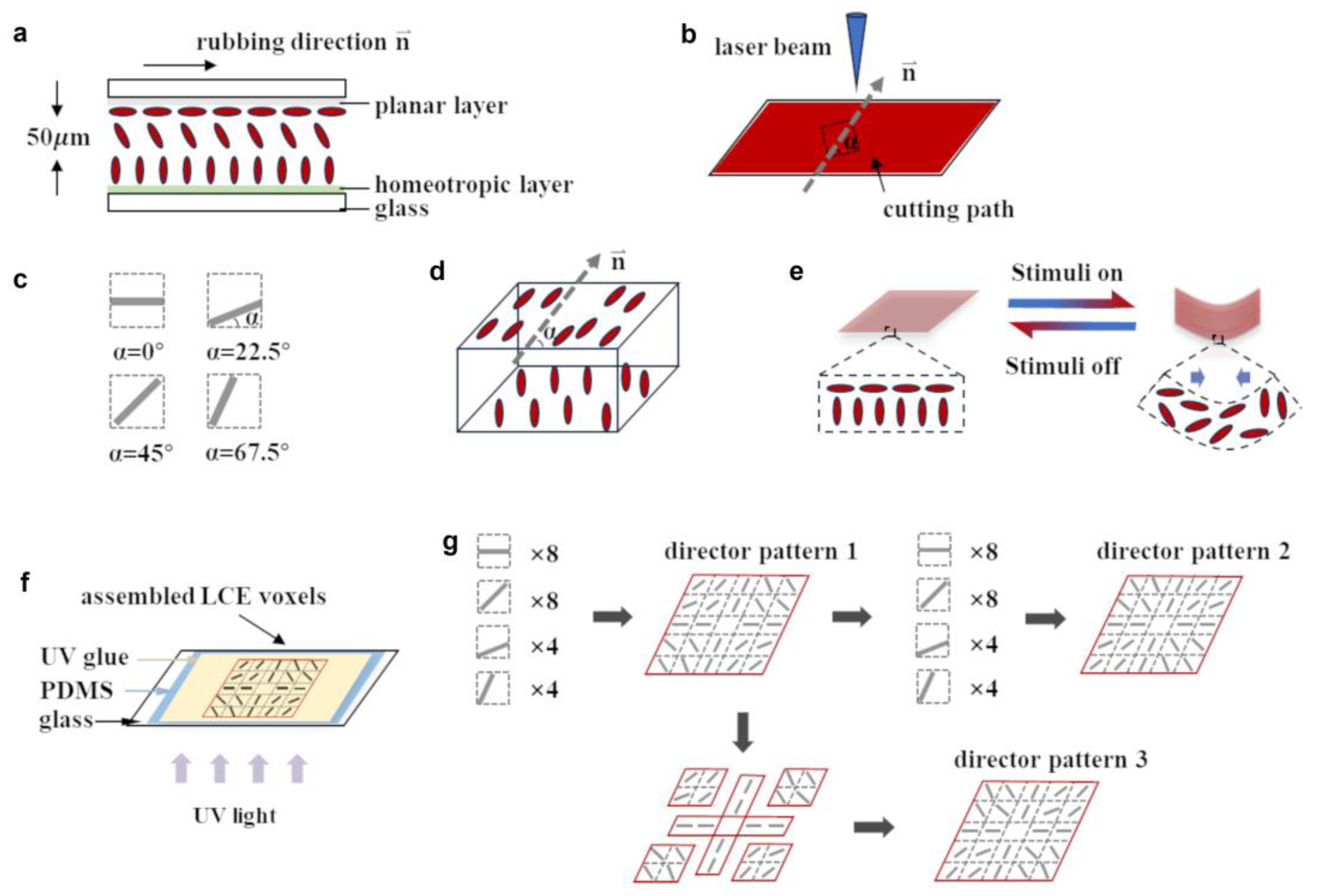
The first critical point is enabled by the surface patterning of LCE film and laser cutting of the LCE film along designed orientations. As schematically shown in Figure 1a, we fabricated LCE films with planar alignment on the bottom surface and perpendicular alignment on the top surface, which corresponds to splay alignment. The chemical composition of LCE and the correspondingly weight ratio were presented in Figure S1. To verify the alignment of LCE, we checked polarized microscope images of uniform alignment and splay alignment, both of which were adopted in our research. Furthermore, the images indicated the good alignment quality of our samples (see Figure S6). Square-shaped LCE pixels with designable director fields can be achieved if we cut the film along corresponding orientations (α in Figure 1b). For example, we schematically present four pixels with different top-surface director fields (different α) in Figure 1c. Note that these pixels have splay alignment (Figure 1d). This kind of splay alignment results in a bending shape morphing towards the top surface along the planar alignment direction of each pixel (Figure 1e) [17,29]. Order change is a function with respect to temperature; in particular, at relatively low temperature, the order change might be much smaller than the one drawn in Figure 1e. We remark that we choose the splay alignment and square shapes of pixels for simplicity in pixel assembly and the design of shape morphing modes. In fact, we can select various director fields and shapes of pixels, to increase the design freedom.

Figure 1.
Schematic of reconfigurable LCE director patterns. (a) Schematic LCE director field. (b) LCE pixels with different director fields fabricated through laser cutting, where α is the angle between the planar alignment direction and one cutting edge. (c) A series of square pixels with different director fields. (d) Schematic 3D LCE director field of a single pixel. (e) Schematic morphing mode of an LCE pixel. (f) Schematic of LCE pixel assembly process. Pixels are assembled on the spin-coated UV glue and are sticked together after UV curing. (g) Schematic of LCE director pattern reconfiguring process.
The second critical point is realized by using UV glue to stick assembled pixels with designed director patterns into an LCE film (Figure 1f). We can design the director pattern of an LCE film and select pixels with proper director fields. These pixels are assembled on top of a thin layer of spin-coated UV glue. After UV curing, these pixels will stick together to form an LCE film with the designed director pattern.
The third critical point is fulfilled by cutting the assembled LCE film into original pixels or completely different pixels, as schematically shown in Figure 1g. Note that we can cut the LCE film partially or along different lines to form new pixels. These pixels, either original pixels or new pixels, can be used to form a new LCE film with distinct designed director patterns.
2.2. Effect of UV Glue and Pixel Geometry on Shape Morphing
We proposed to use UV glue to assemble pixels into LCE films with designed shapes and director patterns. It is important to explore the effect of UV glue film and pixel geometry on shape morphing. The most ideal situation is that neither the UV glue film nor pixel geometry introduces obvious changes on shape morphing.
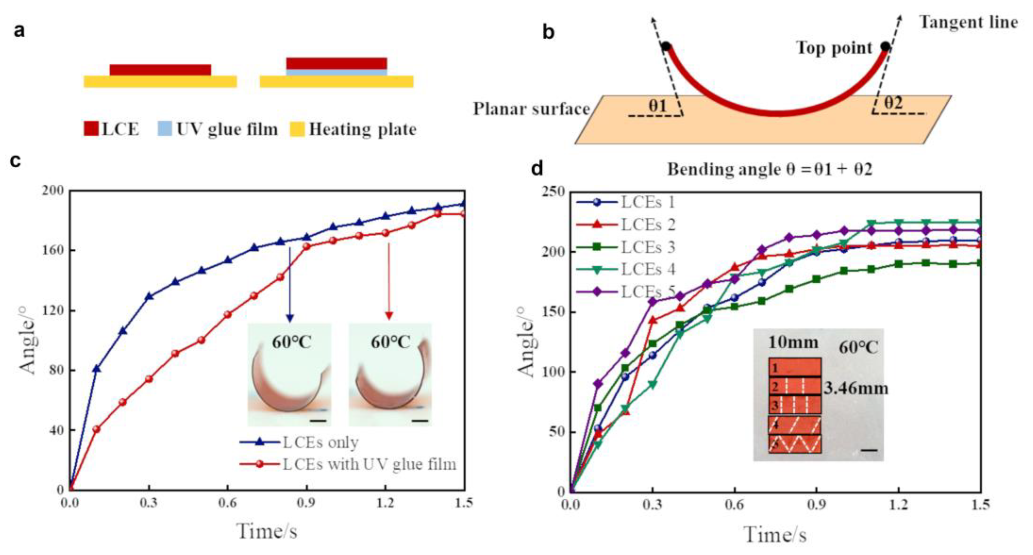
We firstly investigated the effect of UV glue film on the LCE shape morphing (see Figure S2 for more details). We mixed UV glue 9310 and 9300 in a 1:1 weight ratio for a proper adhesion performance, and we spin-coated the UV glue mixture onto a PDMS (Polydimethylsiloxane) layer cured on a glass substrate with a rotation speed of 3000 rpm. An LCE film (6 mm in length and 3 mm in width) with splay alignment was placed on top of the spin-coated UV glue. After UV curing, the LCE film and UV glue film will stick together firmly, which will be peeled off from PDMS. Another LCE film without UV glue film is used for comparison. Then, these two samples are heated to 60 °C to compare their shape morphing behaviors (Figure 2a). We measured the bending angle θ of LCE films by adding the two bending angles ( and ) of each end (Figure 2b). We present the time-dependent bending angles of these two samples in Figure 2c, which indicates similar stable bending angles (at 1.5 s). For better explanation of the experimental phenomenon, we conducted tensile tests on these two samples (see Figure S5). The results indicated that the Young’s moduli of the LCE films without UV glue and with UV glue were 11.6 Mpa and 9.6 Mpa, respectively. To further illustrate the effect of UV glue on shape morphing, we also established a simplified physical model (see Figure S10 for more details). Undoubtfully, the thickness of UV glue film will affect the morphing performance. However, the influences introduced by UV glue are acceptable in our research due to the relatively small thickness of UV glue film (almost 25 μm, see Figure S4) and its low Young’s modulus. Note that the LCE film with UV glue had a slower responding speed compared to the one without UV glue, which is reasonable since the presence of the UV glue film decreases the heat transfer speed. These experimental results prove the feasibility of UV-glue-assembled pixels.

Figure 2.
Effect of UV glue and pixel geometry on shape morphing of LCE. (a) Schematic heating setup of LCE with and without UV glue. (b) Method to measure bending angle for LCE films. (c) Bending angles of LCE film with and without UV glue as a function of time. Insets: photographs of LCE films at 1.5 s response time. (d) Bending angles of LCE films assembled with different pixels as a function of time. Insets: photographs of LCE films assembled with different pixels before shape morphing. All scale bars are 3 mm.
We then explored the effect of pixel geometry on LCE shape morphing. Both pixel size and pixel shape might be important in affecting the shape morphing of LCE films. Therefore, we assembled LCE films with pixels of different sizes (film 2 and film 3 in Figure 2d) and shapes (film 4 and film 5 in Figure 2d) and compared their shape morphing behavior with an LCE film that was directly fabricated (film 1 in Figure 2d). The time-dependent bending angles presented in Figure 2d indicate all films have similar stable bending angles and responding speeds, which is favorable for the further design of assembled LCEs with programmable director patterns. In other words, as long as the geometry and the director pattern are the same, the differences between directly fabricated LCEs and the assembled LCEs is acceptable for reconfiguring experiments. Therefore, we can use pixels with various shapes and sizes to create desired assembled LCEs, which further enhances the versatility of our proposed strategy. We remark that the operating temperature of the LCE is between room temperature and 90 °C in this manuscript. However, the nematic–isotropic transition temperature of the LCE is as much as 200 °C [30], which allows for an operating temperature between room temperature and 200 °C.
2.3. Demonstration of Programmable Complex LCE Director Pattern from Pixels
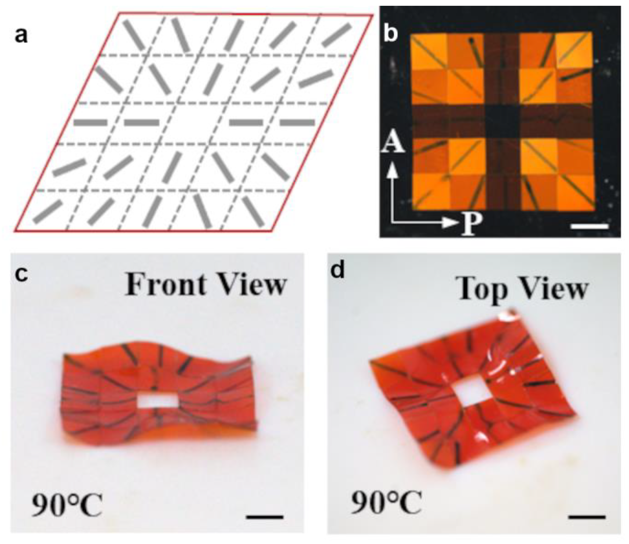
We demonstrated the ability to fabricate LCE films with complex designable director patterns by assembling selected pixels with a proper director field. As schematically shown in Figure 3a, we assembled 24 pixels into an LCE film with a +1 topological defect. Note that we only used the four types of pixels schematically shown in Figure 1c. Each pixel can be rotated by 90 to form a pixel with a different director field.

Figure 3.
Optical characterization and shape morphing of LCE film assembled with square pixels. (a) Schematic of +1 topological defect director fields of an LCE film assembled from pixels. (b) Polarized optical microscope image of the assembled LCE film, taken at room temperature. P and A represent polarizer axis and analyzer axis respectively. (c,d) Front (c) and top view (d) of LCE film when heated to 90 °C. Black lines in (b–d) represent director fields of each pixel. All scale bars are 3 mm.
The polarized optical microscope image (Figure 3b) shows a dark cross, which represents a typical liquid crystal topological defect with charge 1. We observed pixels with 3 types of light transmittance, corresponding to pixels with , , and or . Here, we used pixels with planar alignment on both the top and bottom surfaces (instead of splay alignment) for better characterization of the assembled LCE under a polarized microscope. We then investigated the shape morphing behavior of the assembled LCE film. Figure 3c,d present a front view and top view of the film at 90 °C, which show a typical saddle shape. These results indicate that assembled LCE films with complex director patterns show similar shape morphing behaviors as directly fabricated LCE films [20], which is favorable for designing the shape morphing of assembled LCE films.
2.4. Reconfiguration of LCE Director Patterns
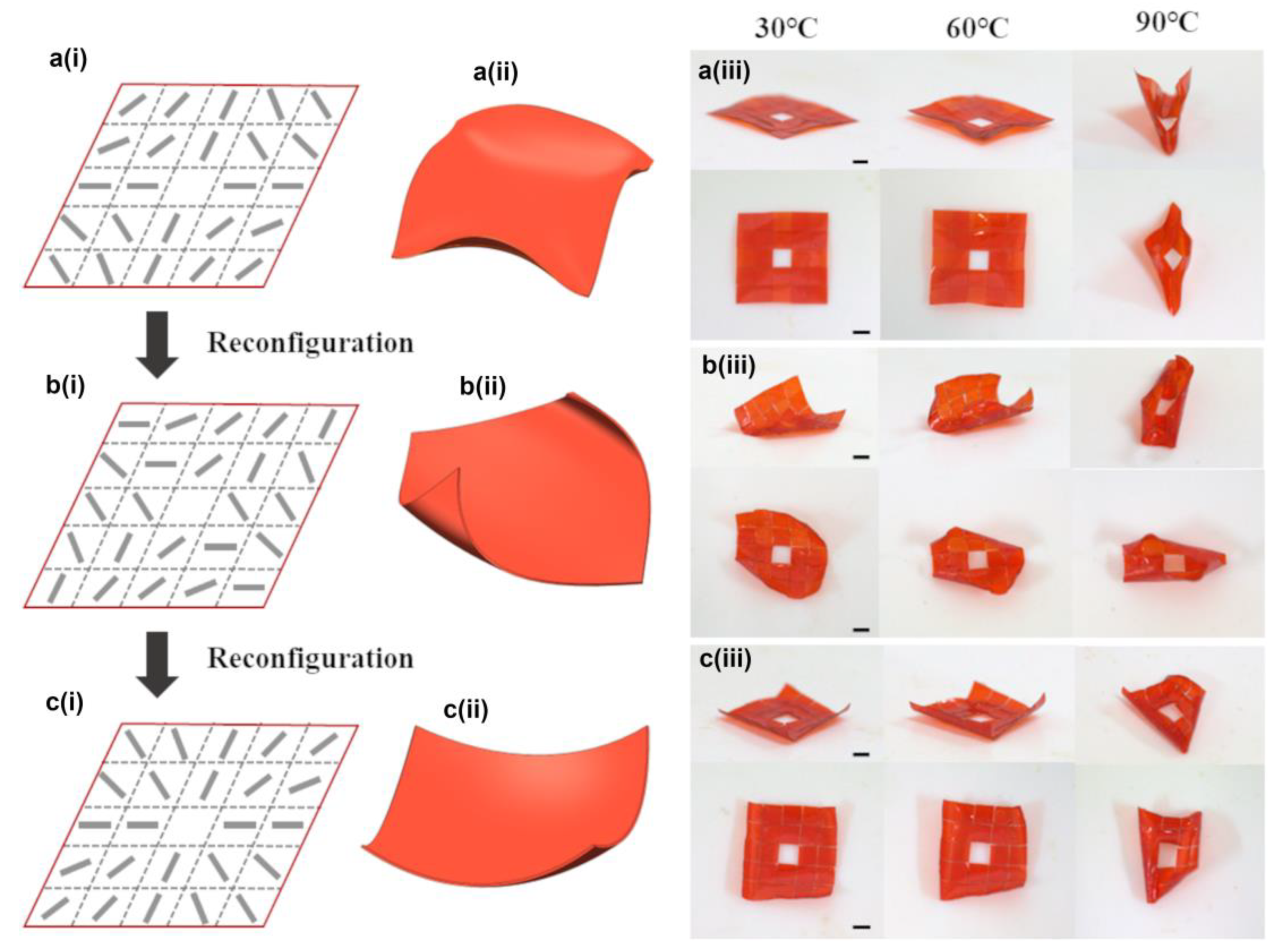
We then explored the ability to reconfigure LCE director patterns by using pixels with splay alignment. We firstly designed an LCE film with a director pattern corresponding to a −1 topological defect with a 0 initial phase, as schematically shown in Figure 4a(i). We selected 24 pixels divided into 4 types, the same as those presented in Figure 1c. We then heated the film to 30 °C, 60 °C, and 90 °C sequentially to investigate the shape morphing behaviors. The polarized optical microscope images of the LCE at different temperatures implied different order parameters (see Figure S8 for more details) [31,32,33]. We present the side view (top row) and top view (bottom row) of the morphed shape in Figure 4a(iii). At 60 °C, we observed a four-fold symmetric shape. For better understanding, we schematically show the corresponding shape in Figure 4a(ii). At 90 °C, the shape morphing along one diagonal direction dominates due to the non-uniformity of heat.

Figure 4.
Reconfiguration of LCE director pattern. (a(i–iii)) Schematic director pattern (a(i)), schematic shape morphing (a(ii)), and experimental shape morphing (a(iii)) of LCE film with a director pattern of a −1 topological defect with 0 initial phase. (b(i–iii)) Schematic director pattern (b(i)), schematic shape morphing (b(ii)), and experimental shape morphing (b(iii)) of LCE film with a director pattern of a −1 topological defect with initial phase. (c(i–iii)) Schematic director pattern (c(i)), schematic shape morphing (c(ii)), and experimental shape morphing (c(iii)) of LCE film with a director pattern of a +1 topological defect with 0 initial phase. All scale bars are 3 mm.
We then de-assembled the LCE film into original pixels (see Figure S3 for more details) and re-assembled these pixels into a new film with a director pattern corresponding to a −1 topological defect with initial phase (Figure 4b(i)). We also performed experiments to prove the durability (see Figure S7) and reversibility of the LCE (see Figure S9). At 60 °C, we observed a bending shape morphing along one diagonal (Figure 4b(iii)). Finally, we de-assembled the LCE film into original pixels again and re-assembled these pixels into a new film with a director pattern corresponding to a +1 topological defect with 0 phase (Figure 4c(i)). At 60 °C, we observed a four-fold symmetric shape (Figure 4c(iii)) which differed from Figure 4a(iii).
We notice that in Figure 4a(i), the director fields are always perpendicular to two diagonals if we track the local director field along these diagonals; this causes expansion of the top surface along two diagonals upon actuation and makes the four corners bend downward. In contrast, director fields are always parallel to two diagonals in Figure 4c(i), which results in contraction of the top surface along two diagonals upon actuation and makes the four corners bend upwards. In addition, director fields are always 45 to two diagonals in Figure 4b(i), and the shape morphing is apparently different from the previous two cases.
In this section, we demonstrated the reconfiguration ability of LCE director patterns by the assembly and de-assembly of LCE pixels with a selected director field. Through two-times reconfiguration of the director pattern, we achieved three distinct shape morphing modes. We remark that more shape morphing modes can be realized by multi-times reconfiguration.
2.5. Reconfiguration of Both LCE Shapes and Director Patterns
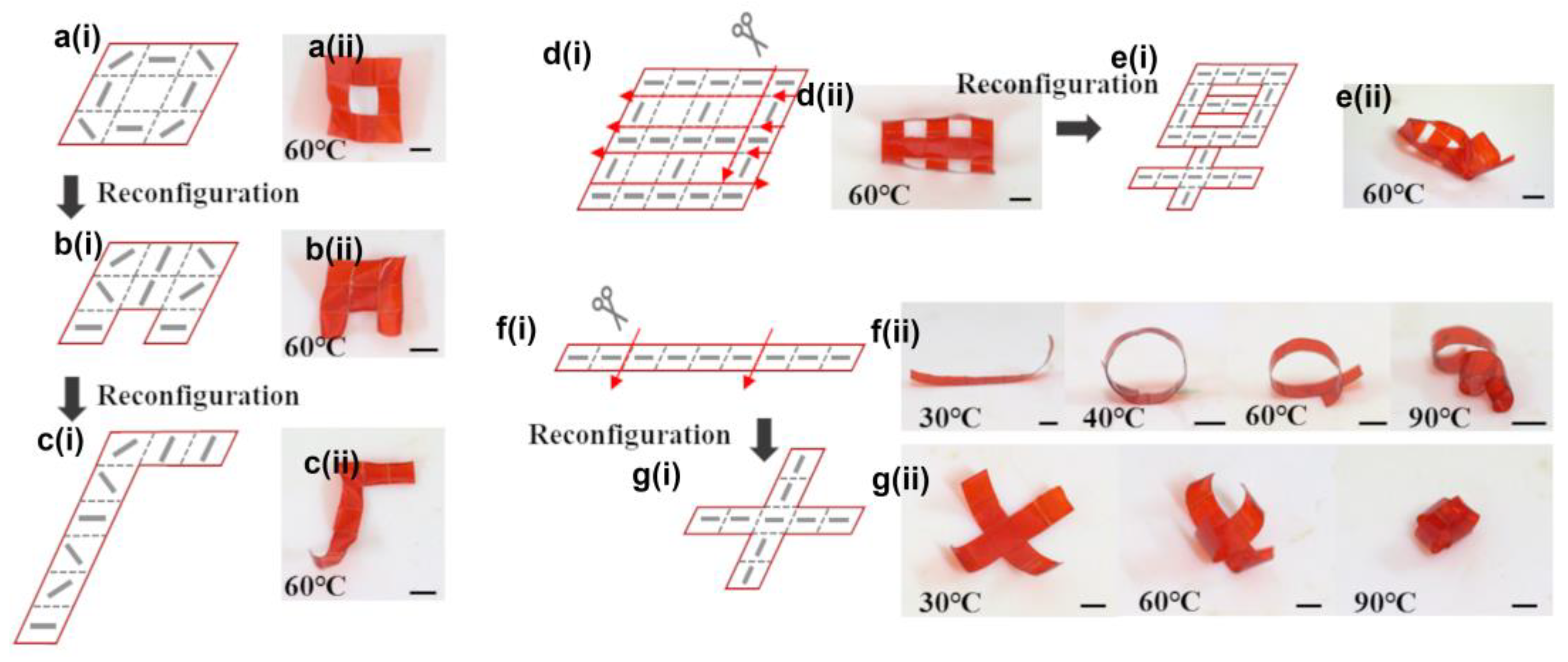
Reconfiguration of the director patterns already enables multiple shape morphing modes. We further explored the ability to reconfigure LCE shapes and director patterns simultaneously to allow for more shape morphing modes. We firstly assembled an LCE square ring with circular alignment using 8 pixels (Figure 5a(i,ii)) and then reconfigured both the shape and director pattern of the square ring to obtain N-shaped film with an axially symmetric director pattern (Figure 5b(i,ii)); this was finally reconfigured into an L-shaped film with complex director pattern (Figure 5c(i,ii)). The shape morphing behaviors of these three films are completely different. Therefore, we can design shape morphing modes through reconfiguring both the initial shapes and director patterns of LCE films.

Figure 5.
Reconfiguration of both LCE shapes and director patterns. (a(i,ii)–c(i,ii)) Multi-mode shape morphing realized with 8 pixels. (d(i,ii),e(i,ii)) LCE director pattern and shape reconfiguration between two Chinese characters. (f(i,ii),g(i,ii)) Reconfiguration between a helix and a gripper realized through reconfiguration of LCE director patterns and shapes. Red arrows in figures represent cutting tracks. All scale bars are 3 mm.
We then demonstrated the flexibility of our reconfiguring strategy to partially de-assemble the LCE films and introduce a new LCE film with programmable shape and director pattern. For example, we firstly assembled an LCE film with the shape of the Chinese character “田” using 21 pixels with (Figure 5d). We then selectively separated the LCE film into 11 pixels via 8 cuttings (red arrows in Figure 5d). We finally assembled these 11 pixels into another Chinese character “早” (Figure 5e). We obtained distinct shape morphing modes from these two films.
We finally demonstrated multi-functions of LCE-based soft robots, enabled by the reconfiguration of LCE films. We firstly assembled nine pixels (using an director field) into a stripe, which transformed into a circle at 40 °C and a helix above 60 °C (Figure 5f). We then de-assembled the stripe into three pixels with two cuttings (red arrows in Figure 5f) and assembled the three pixels into a cross shape, which could work as a gripper at high temperature (Figure 5g(ii)). The helix [5] and gripper [17] are widely used in soft robotics for locomotion and grabbing, respectively. Reconfiguration between these two shapes may allow for cargo transportation and more functions. We expect the reconfiguration of LCE shapes and director patterns will introduce more advanced functions of LCE-based soft robots.
3. Discussion
In this research, we demonstrated a strategy to reconfigure both LCE director patterns and LCE initial shapes for improving multi-mode shape morphing. Compared with previous researches [26,27,28], one obvious advantage of this work lies in the reconfiguration of complex LCE director patterns. For simplicity, we demonstrated the reconfiguration of LCE director patterns assembled from 24 square-shaped pixels (Figure 4). We remark that different numbers of pixels with various designable initial shapes can be applied to further improve the complexity of achievable LCE configurations and thus complex shape morphing modes.
In principle, we should be able to reconfigure LCE director patterns and LCE initial shapes for an unlimited number of times. Ideally, we need a reversible glue to transfer between adhesion and non-adhesion states. However, even though we tried our best, we could not find this kind of glue. The glue we used cannot be removed after de-assembly of our LCE films, and for each reconfiguration process, the new LCE film will add a new layer of UV glue. This significantly reduces the number of times we can reconfigure the LCE films. Furthermore, a smaller thickness of UV glue will minimize the influence on the shape morphing of assembled LCE structures. We expect a newly developed reversible glue can solve this problem and enable unlimited times reconfiguration of the LCE director patterns and initial shapes. Further improvement includes the application of a larger LCE pixel thickness and gluing the pixels on the sides.
We also use manual assembly in this research to assemble pixels into LCE films, which restricts the assembly efficiency; furthermore, it is time-consuming to assemble a large number of pixels and it is difficult to assemble pixels on the micrometer scale. Therefore, we believe self-assembly should be incorporated in our reconfiguration in the future, to significantly improve our strategy. In this research, we focused on assembling pixels into two-dimensional (2D) LCE films. In fact, the strategy demonstrated can be easily applied in reconfiguring three-dimensional (3D) LCE structures. In addition, as the LCE pixels were fabricated by laser beam, we could design arbitrary shapes and sizes of the LCE pixels, even down to the micro-scale. Considering the manual assembly process, the minimum controllable size of the pixel would be 50 μm [25].
To improve the versatility of the proposed strategy on the reconfiguration of the LCE director pattern, we proposed the following future studies: (1) self-assembly processes to gather pixels into desired shapes and director patterns with high efficiency; (2) a better glue to stick pixels together so that they can be de-assembled via a simple method; and (3) the 3D assembly of voxels. We believe an improved reconfiguration strategy of LCE director patterns will find enhanced applications in soft robotics, medical micro-robotics, reconfigurable origami/kirigami, and so on.
4. Conclusions
In conclusion, we demonstrated a strategy to reconfigure both LCE director patterns and initial shapes for multi-mode shape morphing. We firstly fabricated LCE pixels with designed director fields by using surface alignment and laser cutting, and we further demonstrated the reconfiguration of both LCE director patterns and LCE shapes by the assembly and de-assembly of pixels with designed director fields. In particular, we can de-assemble LCE films into pixels different from the original ones, improving the flexibility of our reconfiguration strategy. We finally showed that this strategy enabled multi-functions of LCE-based soft robotics. We believe these demonstrated capabilities will enable more advanced functions of LCE based actuators.
5. Materials and Methods
Materials: The LCE was made from a mixture containing 65 wt% of liquid crystal monomer Rm006, 32 wt% LC monomer Rm257, 2 wt% of light-responsive molecule N-Ethyl-N-(2-hydroxyethyl)-4-(4-nitrophenylazo) aniline (Disperse Red 1, Sigma Aldrich (St. Louis, MO, USA)), and 1 wt% of photo-initiator (2-benzyl-2-dimethylamino-4-morpholinobutyrophenone, MERYER), in which Rm006 and Rm257 served as acrylate-functionalized LC monomers and LC crosslinker, respectively. Disperse Red 1 was added as red dye to color materials for convenience in operation and observation. The weight ratio of RM006 and RM257 was selected as approximately 2:1, which benefits the alignment of LCE during the fabrication process. All materials were used as received. UV glue (Type 9310 (Shenzhen Tegu New Material Co., Ltd., Shenzhen, China)) was used to assemble two glasses into a liquid crystal cell. PDMS was mixed in a 10:1 weight ratio and then spin-coated on the glass. After curing at high temperature (e.g., 100 °C), the PDMS film served as the surface on which UV glue was spin-coated for better separation of the assembled LCEs films from the glass substrate. An UV glue mixture of Type 9310 and Type 9300 (Shenzhen Tegu New Material Co., Ltd., Shenzhen, China) with a weight ratio of 1:1 was prepared to balance the adhesion and Young’s modulus for pixel assembly.
Liquid crystal cells: To fabricate liquid crystal cells, two glass substrates were first cleaned for 15 min using ultrasound and then for 40 min using UV ozone. After that, the glass substrates were either spin-coated with a 2 wt% water solution of polyvinyl alcohol with a rotation speed of 4000 rpm for 30 s or spin-coated with PI1211 at a rotation speed of 1500 rpm for 30 s, respectively. The PVA-coated glass substrate and the PI1211 coated substrate were heated at 120° for 10 min and at 180° for 30 min. After cooling, the PVA-coated glass slide was rubbed unidirectionally with a cloth for uniform planar alignment and subsequently blown with air blast to remove surface dust particles. Tiny drops of UV glue were picked up by sharp needle and placed on the four corners of the PVA-coated substrate. Then, the PI1211-coated substrate was assembled with the PVA-coated substrate to form a cell. Note that spherical spacers of 50 μm diameter were mixed in the UV glue to determine cell thickness. After that, an UV LED was used to cure the UV glue.
LCE films: To prepare LCE films, the monomer mixture was magnetically stirred at 150 °C for 5 min. Then, the mixture was filled into the cell by a capillary force at 150 °C and cooled down to room temperature to reach the nematic phase for programmed alignment. Note that the whole process needed to be performed in the absence of light. Then, we used the UV LED to polymerize the LC mixture for 2 h. After curing via the UV LED, the LC cell was opened from one side by blade. Then, we used the laser beam to cut LCEs into pixels according to our design. In particular, the model of the laser equipment was AMT-1064-20-100-W (Industrial Picosecond Lasers, Advanced Optowave Corporation, Ronkonkoma, NY, USA) and the wavelength of the laser beam was 1064 nm. Moreover, the related parameters we applied were as follow: power: 500 w; repetition rate: 200 kHz; velocity: 400 mm/s; and cycle times: 300.
Pixel assembly: To assemble pixels into an LCE film, a glass substrate was thoroughly cleaned for 15 min using ultrasound and then spin-coated with PDMS mixture at a speed of 2500 rpm for 30 s. The coated glass was then cured on a heating plate at 100 °C for 10 min to form a PDMS film. After that, the PDMS film was spin-coated with UV glue mixture at a speed of 3000 rpm for 30 s. Then, pixels with designed director fields were assembled on top of the UV glue mixture. After curing of the glue, the LCE film was peeled off from the PDMS substrate.
Supplementary Materials
The following supporting information can be downloaded at: https://www.mdpi.com/article/10.3390/cryst14040357/s1, Figure S1. Chemical composition of LCEs and the corresponding weight ratios. Figure S2. Effect of different UV glues on LCE shape morphing. Figure S3. De-assembly of an LCE film into pixels. Figure S4. Thickness of UV glue layer. Figure S5. Stress–strain curve for LCE without (a) and with (b) UV glue. Figure S6. Polarized optical microscopic images of uniform (a) and splay (b) aligned liquid crystal elastomers. Figure S7. Shape morphing of LCE sample fabricated 3 months prior. Figure S8. Polarized optical images of LCEs at different temperatures. Figure S9. Bending angle of LCE film measured with respect to heating–cooling cycles. Figure S10. Normalized curvature with respect to thickness of two layers. Movie S1. Effect of UV glue on shape morphing of LCE. Movie S2. Effect of pixel geometry on shape morphing of LCE. Movie S3. Reversibility experiment for LCEs.
Author Contributions
Y.G. and T.Z. conceived of the research. X.Z. performed most of the experiments. X.Z., L.L., J.S., R.D., X.X., B.X. and G.W. analyzed the data. X.Z., T.Z. and Y.G. wrote the manuscript with input from all the other authors. All authors have read and agreed to the published version of the manuscript.
Funding
This work was supported by the National Natural Science Foundation of China through project 52375560.
Data Availability Statement
The original contributions presented in the study are included in the article and Supplementary Materials, further inquiries can be directed to the corresponding authors.
Conflicts of Interest
The authors declare no conflicts of interest.
References
- Tajbakhsh, A.R.; Terentjev, E.M. Spontaneous thermal expansion of nematic elastomers. Eur. Phys. J. E 2001, 6, 181–188. [Google Scholar] [CrossRef]
- Küpfer, J.; Finkelmann, H. Nematic liquid single crystal elastomers. Makromol. Chem. Rapid Commun. 1991, 12, 717–726. [Google Scholar] [CrossRef]
- Hebner, T.S.; Korner, K.; Bowman, C.N.; Bhattacharya, K.; White, T.J. Leaping liquid crystal elastomers. Sci. Adv. 2023, 9, eade1320. [Google Scholar] [CrossRef] [PubMed]
- Li, Y.; Liu, Y.; Luo, D. Polarization Dependent Light-Driven Liquid Crystal Elastomer Actuators Based on Photothermal Effect. Adv. Opt. Mater. 2021, 9, 2001861. [Google Scholar] [CrossRef]
- Zhang, J.; Guo, Y.; Hu, W.; Soon, R.H.; Davidson, Z.S.; Sitti, M. Liquid Crystal Elastomer-Based Magnetic Composite Films for Reconfigurable Shape-Morphing Soft Miniature Machines. Adv. Mater. 2021, 33, 2006191. [Google Scholar] [CrossRef] [PubMed]
- Shin, J.; Kang, M.; Tsai, T.; Leal, C.; Braun, P.V.; Cahill, D.G. Thermally Functional Liquid Crystal Networks by Magnetic Field Driven Molecular Orientation. ACS Macro Lett. 2016, 5, 955–960. [Google Scholar] [CrossRef] [PubMed]
- Yao, Y.; Waters, J.T.; Shneidman, A.V.; Cui, J.; Wang, X.; Mandsberg, N.K.; Li, S.; Balazs, A.C.; Aizenberg, J. Multiresponsive polymeric microstructures with encoded predetermined and self-regulated deformability. Proc. Natl. Acad. Sci. USA 2018, 115, 12950–12955. [Google Scholar] [CrossRef] [PubMed]
- Schuhladen, S.; Preller, F.; Rix, R.; Petsch, S.; Zentel, R.; Zappe, H. Iris-Like Tunable Aperture Employing Liquid-Crystal Elastomers. Adv. Mater. 2014, 26, 7247–7251. [Google Scholar] [CrossRef] [PubMed]
- McConney, M.E.; Martinez, A.; Tondiglia, V.P.; Lee, K.M.; Langley, D.; Smalyukh, I.I.; White, T.J. Topography from Topology: Photoinduced Surface Features Generated in Liquid Crystal Polymer Networks. Adv. Mater. 2013, 25, 5880–5885. [Google Scholar] [CrossRef] [PubMed]
- Guo, Y.; Shahsavan, H.; Sitti, M. 3D Microstructures of Liquid Crystal Networks with Programmed Voxelated Director Fields. Adv. Mater. 2020, 32, 2002753. [Google Scholar] [CrossRef] [PubMed]
- Xia, Y.; Cedillo-Servin, G.; Kamien, R.D.; Yang, S. Guided Folding of Nematic Liquid Crystal Elastomer Sheets into 3D via Patterned 1D Microchannels. Adv. Mater. 2016, 28, 9637–9643. [Google Scholar] [CrossRef] [PubMed]
- Li, M.-H.; Keller, P. Artificial muscles based on liquid crystal elastomers. Philos. Trans. R. Soc. Math. Phys. Eng. Sci. 2006, 364, 2763–2777. [Google Scholar] [CrossRef] [PubMed]
- Thomsen, D.L.; Keller, P.; Naciri, J.; Pink, R.; Jeon, H.; Shenoy, D.; Ratna, B.R. Liquid Crystal Elastomers with Mechanical Properties of a Muscle. Macromolecules 2001, 34, 5868–5875. [Google Scholar] [CrossRef]
- Yu, Z.; Wang, Y.; Zheng, J.; Sun, S.; Fu, Y.; Chen, D.; Cai, W.; Wang, D.; Zhou, H.; Li, D. Fast-Response Bioinspired Near-Infrared Light-Driven Soft Robot Based on Two-Stage Deformation. ACS Appl. Mater. Interfaces 2022, 14, 16649–16657. [Google Scholar] [CrossRef] [PubMed]
- Huang, Z.; Tsui, G.C.-P.; Deng, Y.; Tang, C.-Y.; Yang, M.; Zhang, M.; Wong, W.-Y. Bioinspired near-infrared light-induced ultrafast soft actuators with tunable deformation and motion based on conjugated polymers/liquid crystal elastomers. J. Mater. Chem. C 2022, 10, 12731–12740. [Google Scholar] [CrossRef]
- Palagi, S.; Mark, A.G.; Reigh, S.Y.; Melde, K.; Qiu, T.; Zeng, H.; Parmeggiani, C.; Martella, D.; Sanchez-Castillo, A.; Kapernaum, N.; et al. Structured light enables biomimetic swimming and versatile locomotion of photoresponsive soft microrobots. Nat. Mater. 2016, 15, 647–653. [Google Scholar] [CrossRef] [PubMed]
- Wani, O.M.; Zeng, H.; Priimagi, A. A light-driven artificial flytrap. Nat. Commun. 2017, 8, 15546. [Google Scholar] [CrossRef] [PubMed]
- Kotikian, A.; Truby, R.L.; Boley, J.W.; White, T.J.; Lewis, J.A. 3D Printing of Liquid Crystal Elastomeric Actuators with Spatially Programed Nematic Order. Adv. Mater. 2018, 30, 1706164. [Google Scholar] [CrossRef] [PubMed]
- Peng, X.; Wu, S.; Sun, X.; Yue, L.; Montgomery, S.M.; Demoly, F.; Zhou, K.; Zhao, R.R.; Qi, H.J. 4D Printing of Freestanding Liquid Crystal Elastomers via Hybrid Additive Manufacturing. Adv. Mater. 2022, 34, 2204890. [Google Scholar] [CrossRef] [PubMed]
- de Haan, L.T.; Sánchez-Somolinos, C.; Bastiaansen, C.M.W.; Schenning, A.P.H.J.; Broer, D.J. Engineering of Complex Order and the Macroscopic Deformation of Liquid Crystal Polymer Networks. Angew. Chem. Int. Ed. 2012, 51, 12469–12472. [Google Scholar] [CrossRef] [PubMed]
- Jiang, M.; Guo, Y.; Yu, H.; Zhou, Z.; Turiv, T.; Lavrentovich, O.D.; Wei, Q. Low f -Number Diffraction-Limited Pancharatnam–Berry Microlenses Enabled by Plasmonic Photopatterning of Liquid Crystal Polymers. Adv. Mater. 2019, 31, 1808028. [Google Scholar] [CrossRef] [PubMed]
- Babakhanova, G.; Turiv, T.; Guo, Y.; Hendrikx, M.; Wei, Q.-H.; Schenning, A.P.H.J.; Broer, D.J.; Lavrentovich, O.D. Liquid crystal elastomer coatings with programmed response of surface profile. Nat. Commun. 2018, 9, 456. [Google Scholar] [CrossRef] [PubMed]
- Tabrizi, M.; Ware, T.H.; Shankar, M.R. Voxelated Molecular Patterning in Three-Dimensional Freeforms. ACS Appl. Mater. Interfaces 2019, 11, 28236–28245. [Google Scholar] [CrossRef]
- Zeng, H.; Martella, D.; Wasylczyk, P.; Cerretti, G.; Lavocat, J.G.; Ho, C.; Parmeggiani, C.; Wiersma, D.S. High-Resolution 3D Direct Laser Writing for Liquid-Crystalline Elastomer Microstructures. Adv. Mater. 2014, 26, 2319–2322. [Google Scholar] [CrossRef] [PubMed]
- Guo, Y.; Zhang, J.; Hu, W.; Khan, M.T.A.; Sitti, M. Shape-programmable liquid crystal elastomer structures with arbitrary three-dimensional director fields and geometries. Nat. Commun. 2021, 12, 5936. [Google Scholar] [CrossRef] [PubMed]
- Wu, Y.; Zhang, S.; Yang, Y.; Li, Z.; Wei, Y.; Ji, Y. Locally controllable magnetic soft actuators with reprogrammable contraction-derived motions. Sci. Adv. 2022, 8, eabo6021. [Google Scholar] [CrossRef]
- Lahikainen, M.; Zeng, H.; Priimagi, A. Reconfigurable photoactuator through synergistic use of photochemical and photothermal effects. Nat. Commun. 2018, 9, 4148. [Google Scholar] [CrossRef] [PubMed]
- Jiang, Z.; Xiao, Y.; Tong, X.; Zhao, Y. Selective Decrosslinking in Liquid Crystal Polymer Actuators for Optical Reconfiguration of Origami and Light-Fueled Locomotion. Angew. Chem. 2019, 131, 5386–5391. [Google Scholar] [CrossRef]
- Lavrentovich, O.D. Prepatterned liquid crystal elastomers as a step toward artificial morphogenesis. Proc. Natl. Acad. Sci. USA 2018, 115, 7171–7173. [Google Scholar] [CrossRef] [PubMed]
- Zeng, H.; Wani, O.M.; Wasylczyk, P.; Kaczmarek, R.; Priimagi, A. Self-Regulating Iris Based on Light-Actuated Liquid Crystal Elastomer. Adv. Mater. 2017, 29, 1701814. [Google Scholar] [CrossRef]
- Pei, Z.; Yang, Y.; Chen, Q.; Terentjev, E.M.; Wei, Y.; Ji, Y. Mouldable liquid-crystalline elastomer actuators with exchangeable covalent bonds. Nat. Mater. 2014, 13, 36–41. [Google Scholar] [CrossRef] [PubMed]
- Ware, T.H.; Perry, Z.P.; Middleton, C.M.; Iacono, S.T.; White, T.J. Programmable Liquid Crystal Elastomers Prepared by Thiol–Ene Photopolymerization. ACS Macro Lett. 2015, 4, 942–946. [Google Scholar] [CrossRef] [PubMed]
- Wu, J.; Yao, S.; Zhang, H.; Man, W.; Bai, Z.; Zhang, F.; Wang, X.; Fang, D.; Zhang, Y. Liquid Crystal Elastomer Metamaterials with Giant Biaxial Thermal Shrinkage for Enhancing Skin Regeneration. Adv. Mater. 2021, 33, 2106175. [Google Scholar] [CrossRef] [PubMed]
Disclaimer/Publisher’s Note: The statements, opinions and data contained in all publications are solely those of the individual author(s) and contributor(s) and not of MDPI and/or the editor(s). MDPI and/or the editor(s) disclaim responsibility for any injury to people or property resulting from any ideas, methods, instructions or products referred to in the content. |
© 2024 by the authors. Licensee MDPI, Basel, Switzerland. This article is an open access article distributed under the terms and conditions of the Creative Commons Attribution (CC BY) license (https://creativecommons.org/licenses/by/4.0/).