1. Introduction
In the last few decades, the application of titanium and its alloys has been highly studied and expanded. Nowadays, those materials can be found in the automotive and aircraft industries [
1,
2,
3]. The good corrosion resistance of titanium and its alloys has also allowed for their application in the marine and nuclear-power engineering fields [
4,
5,
6]. Aluminum and its alloys are very commonly used materials. Aluminum and its alloys are the metals of choice for many manufacturers due to their light weight, good mechanical properties, high plasticity and excellent malleability, good corrosion resistance, and good electrical and thermal conductivity and the possibility of producing high-strength heat-treated components [
7,
8,
9].
Usually, titanium and aluminum alloys are separately welded using different techniques, but gas metal arc welding (GMAW) and gas tungsten arc welding (GTAW) are most commonly used [
10,
11,
12]. Of course, different methods for welding titanium alloys and aluminum alloys such as laser beam welding (LBW) [
13,
14], friction stir welding (FSW) [
15,
16], and electron-beam welding (EBW) [
17,
18] have also been suggested by previous authors. With the expansion of modern applications of well-established materials such as titanium and aluminum, the necessity of realizing non-detachable joints between them in order to form so-called dissimilar joints has increased.
Aonuma et al. [
19] have studied the weldability of different aluminum and titanium alloys. During their work, successful butt joints were formed; however, the presence of intermetallics was detected in the weld seam. This influenced the output mechanical properties of the joint. They also report that as far as friction stir welding is concerned, a higher travel speed is recommended for the formation of a high-strength Al/Ti joint. A novel approach for joining Ti/Al was proposed by Wei et al. [
20] using a welding–brazing technique. They reported an increase in the microhardness in the fusion zone caused by the formation of intermetallic compounds. In their work, Baqer et al. [
21] studied laser beam welding of Ti/Al dissimilar metals using different technological conditions. They also reported a high quantity of Ti
xAl
x intermetallic phases within the weld seam, which reduced the ductility of the seam and thus worsened its mechanical properties. They suggest an offset of the laser beam towards the aluminum plate in order to decrease the amount of intermetallics formed during the process. During previous investigations [
22], the possibility of the formation of Ti6Al4V/Al6082-T6 joints was investigated. An offset towards the Al and the Ti6Al4V plates was also applied, and the results indicated that using those technological conditions, a high quantity of defects formed when welding the dissimilar metals without using an offset and when using an offset towards the Ti plate. Using an offset towards the aluminum plate indeed improved the resultant microstructure/microhardness relationship; however, the formation of intermetallic compounds was still present at the border between the Ti6Al4V and Al6082-T6 plates. As a result, the formed joint exhibited an excellent ultimate tensile strength (UTS) of 157 MPa; however, it was accompanied by a very high yield strength (YS) of 152 MPa, suggesting that the formed joint is characterized by high brittleness.
Due to the unsatisfactory results obtained by the previous study [
22], an additional investigation was performed regarding the topic of electron-beam welding of Ti6Al4V and Al6082 alloys. The effect of the technological conditions on the microstructure and mechanical properties of the obtained joints was studied. During this research, optimal technological conditions were selected for the formation of a high-strength joint. As it is known, the process of electron-beam welding is characterized by the formation of high thermal gradients that form during the welding process [
23]. The isotherms of the thermal field generated during the irradiation of the materials with the electron beam are always directed towards the bottom of the plates. Due to the high thermal input and the high thermal gradients formed during welding with highly concentrated heat sources, high residual stresses typically form in the welded specimens. This also reduces the output mechanical properties of the welds by introducing defects within the weld seam during or shortly after the welding process is performed.
In order to improve on those disadvantages of the EBW process when Ti6Al4V and Al6082-T6 alloys are concerned, all plates were preheated in order to reduce the residual stresses, as a result of which a major decrease in the formation of defects, particularly cracks, was expected. Different approaches in terms of the technological conditions of the process were also investigated in order to reduce the formation of intermetallics to a minimum, and the final results were compared to those obtained previously. The current investigations have led to the obtaining of technological conditions for electron-beam welding of Ti6Al4V and Al6082-T6 alloys with improved mechanical strength and ductility.
2. Materials and Methods
In order to achieve the above-stated goals of this research, Ti6Al4V and Al6082-T6 plates were butt jointed using an electron-beam machine produced by Evobeam GmbH (Nieder-Olm, Germany). The Ti6Al4V plates had the following composition in wt%: 5.5–6.5 Al; 3.5–4.5 V; 0.25 Fe; balance Ti. The Al6082-T6 alloy plates had the following composition in wt%: 0.7–1.3 Si; 0.4–1.0 Mn; 0.6–1.2 Mg; 0.5 Fe; balance Al. The dimensions of the plates were 100 × 50 × 8 mm.
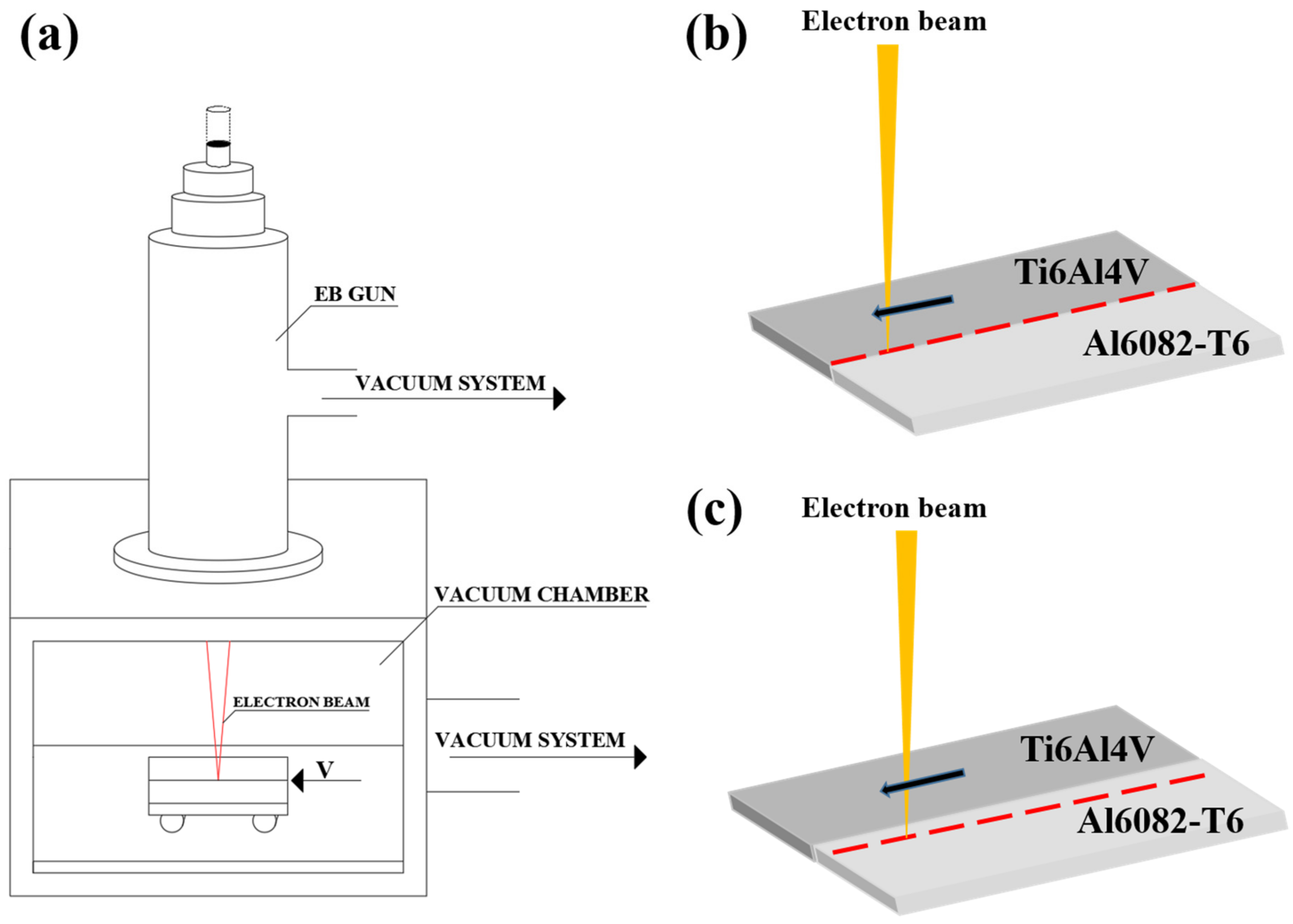
The technological conditions of the electron-beam welding process are summarized in
Table 1. A scheme of the electron-beam welding process is shown in
Figure 1a. The performed welding strategies are shown in
Figure 1b and
Figure 1c, respectively.
Figure 1b shows the no-offset strategy, and
Figure 1c shows the weld process being performed using an offset towards the aluminum plate. During all experiments, the accelerating voltage U
b was kept constant at 60 kV, and all plates were preheated to a temperature T
p of 300 °C in order to reduce the thermal gradient formed during the heating stage and thus reduce the residual stresses. This also improved the miscibility of the materials by artificially exciting the atoms in their crystal lattices. Subsequent to the welding process, the samples were cooled in a high-vacuum environment for 30 min. For the first experiment, similar technological conditions of electron-beam welding of Ti6Al4V and Al6082-T6 to those in a previous work [
22] were employed. No offset was used in this case. The current of the electron beam I
b was set to 35 mA, and the welding speed v
w was set to 10 mm/s. Due to the high welding speed, poor melting of the plates was noticed, accompanied by the formation of an uneven weld seam. Due to this, in the second experiment, the current of the electron beam was set to 20 mA, and the welding speed was reduced to 5 mm/s. The reduction in the current was mandatory due to the utilization of the much lower welding speed. During the previous research, it was established that an offset towards the aluminum plate led to the formation of a strong joint between the aluminum and the titanium alloy, albeit brittle [
22]. Due to this, an attempt to weld the two plates with a 0.5 mm offset towards the aluminum side was made. The heat input achieved during the welding process was calculated using the heat input formula described by the authors of [
24]. Of course, a different coefficient of efficiency k was used in the present case for electron-beam welding.
In order to study the microstructure of the joints, micrographic samples were prepared by cutting a piece of the cross-section of the joints. The formed samples were ground using abrasive paper up to a grit size of P2500. The Al6082-T6 side of the samples was etched using Keller’s reagent with the following composition: 2.5 mL HNO3, 1.5 mL HCl, 1.0 mL HF, and 95 mL dH2O. The Ti6Al4V side of the sample was etched using a reagent with the following chemical composition: 2.0 mL HNO3, 1.5 mL HF, and 10 mL dH2O. During the etching procedure, every sample was swabbed with each reagent for 30 s.
X-ray diffraction was used in order to assess the phase composition of the formed joints. The experiments were carried out on a Bruker D8 Advance diffractometer (Bruker Corp., Billerica, MA, USA). The diffractograms were prepared using a 25–85 degree range on the 2θ scale. CuKα radiation was used with a wavelength of 1.54 Å. All measurements were performed in the middle of the formed fusion zone.
Scanning electron microscopy was used in order to obtain detailed information regarding the microstructure of the weld joints. A Lyra I XMU Tescan (Czech Republic) unit was used in all cases. Each sample was scanned with an accelerating voltage of 20 kV.
The mechanical properties of the samples were determined by measuring their microhardness and their tensile properties. The microhardness was determined according to the Vickers hardness scale. For the purpose of this experiment, a Zwick Roell Indentec-ZHV μ-S microhardness tester (Zwick Roell GmbH, Ulm, Germany) was used. The values for the microhardness were obtained 1 mm below the surface of the plates (the weld seam) and 3 mm below the surface. A force of 0.05 N was used in all cases with a dwell time of 10 s. The measurements were performed following the ISO 6507-1 standard [
25] for performing microhardness tests.
The tensile properties were determined by a Zwick Roell Vibrophore 100 (Zwick Roell GmbH, Ulm, Germany) tensile tester. The measurements were performed at a static stress rate of 30 MPa/s following the ISO 6892-1 standard [
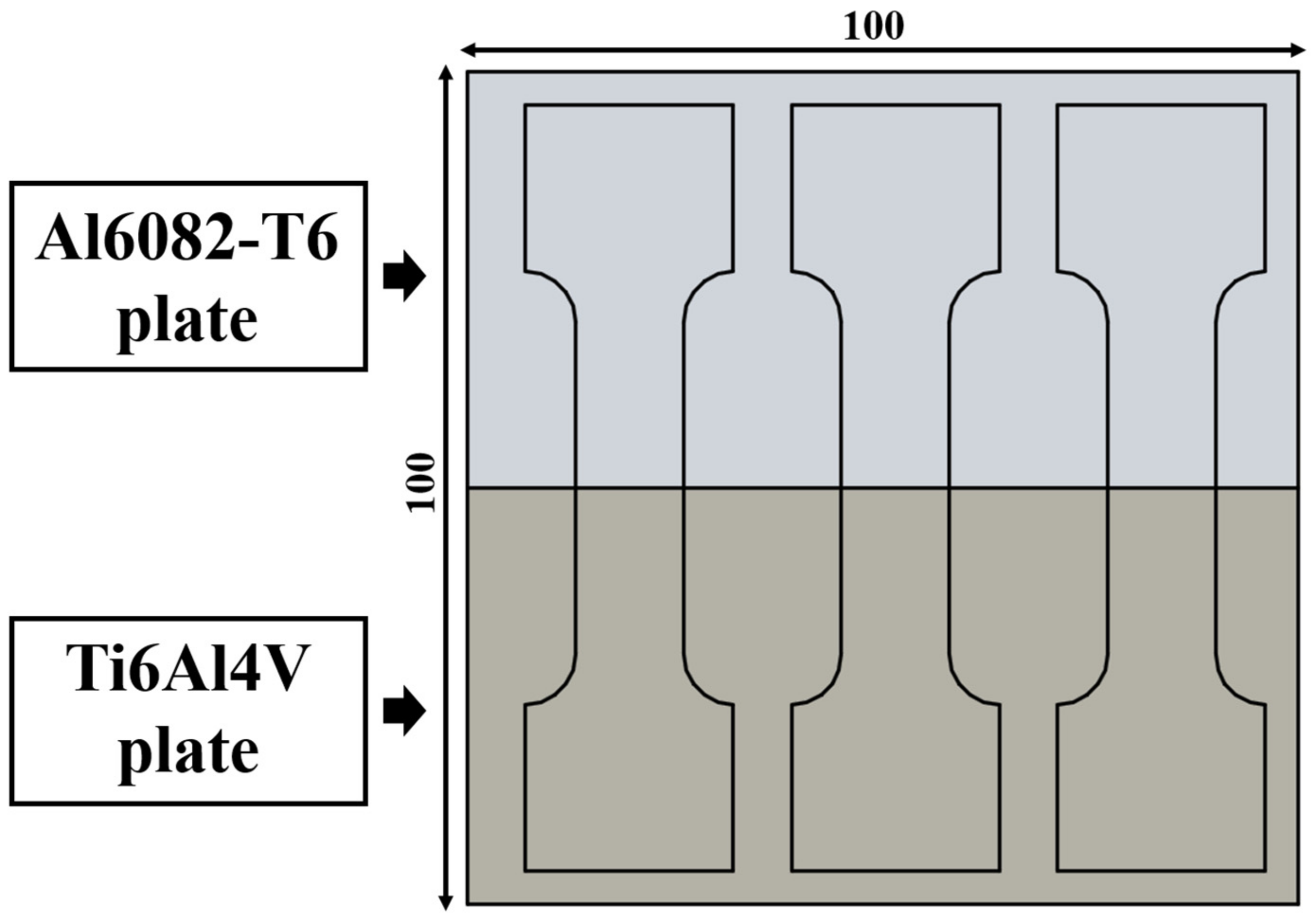
26]. The dimensions of the tensile test samples are depicted in
Figure 2a, and a 3D representation of the samples is shown in
Figure 2b. Due to the size limitations of the used plates, a maximum number of three samples was obtained for each iteration of the used technological conditions, as suggested in
Figure 3. The stress–strain curves obtained during the experiments indicate the engineering stress–strain values that correspond directly to each considered sample.
3. Results
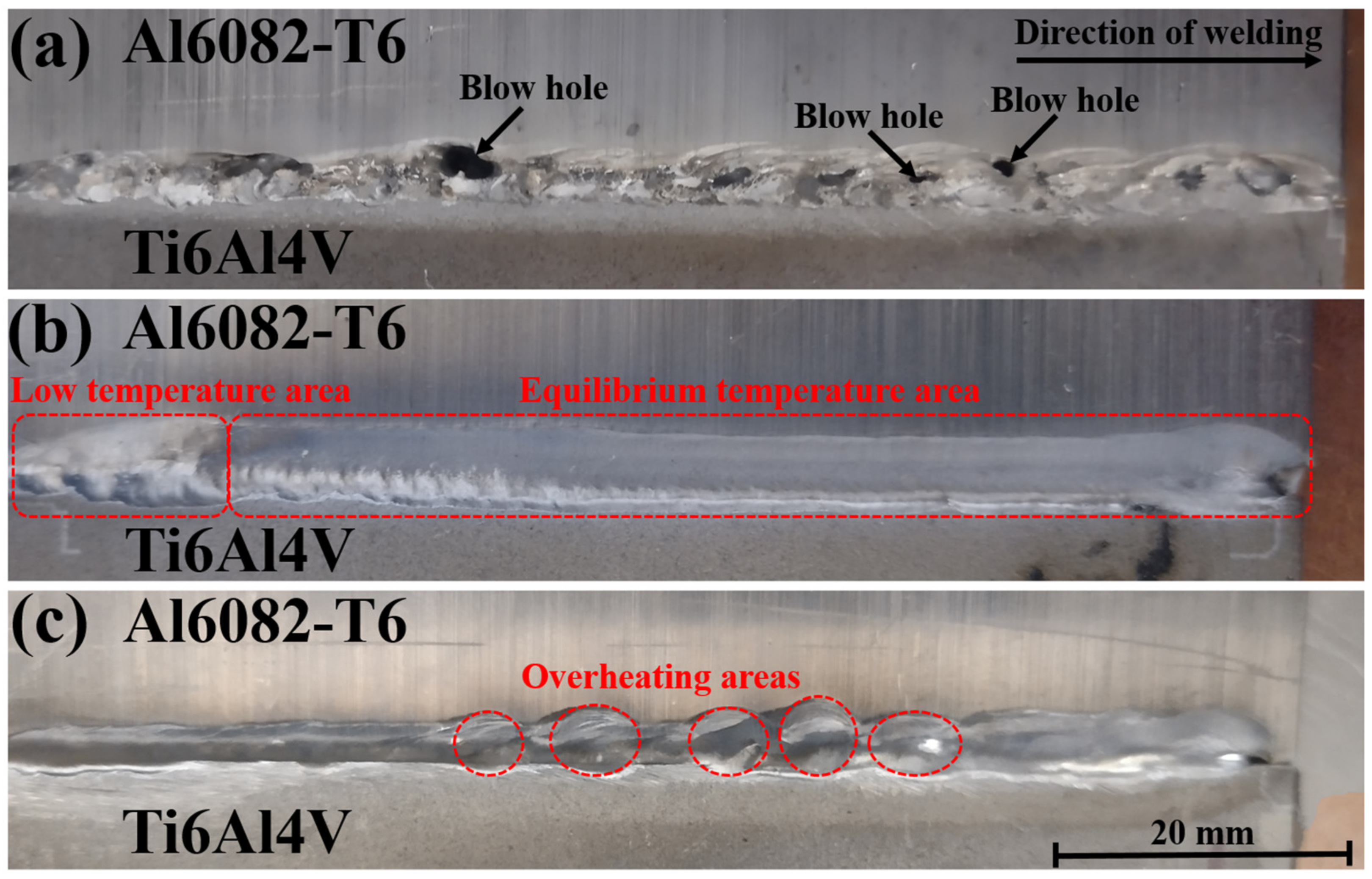
Figure 4 shows an over-the-top image of the formed welds using the different technological conditions formally named A, B, and C. Major defects in the form of blow holes are visible when studying sample A (
Figure 4a). The formed weld is highly inhomogeneous, suggesting low miscibility of the molten materials. When studying sample B (
Figure 4b), a low-temperature area is visible where the EBW process starts. This zone is formed due to the direct heating the plates are subjected to. Once an equilibrium temperature is reached, an even and homogeneous welding seam is formed. Sample C is shown in
Figure 4c. The EBW process begins by forming an even weld seam. Due to the offset towards the aluminum side, overheating of the aluminum occurs, and the weld seam’s width gradually increases.
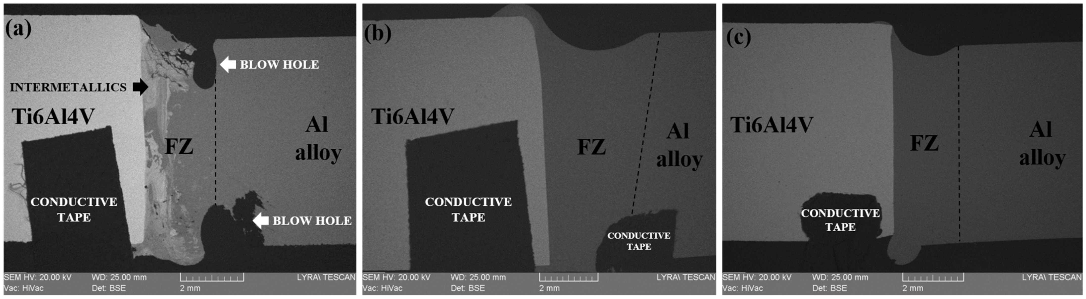
The macrostructures of the cross-sections of samples A, B, and C are shown in
Figure 5.
Figure 5a shows the fusion zone (FZ) between the Ti6Al4V and the Al alloy of sample A in the BSE mode. Large blow holes are observed both at the top and at the bottom of the weld seam. Defects such as pores are also noticeable at the bottom and top sections of the sample. Structures differing from the raw materials are also seen, which are most probably the result of the formation of Ti
xAl
x compounds. The fusion zone in this case due to the high electron-beam current has a rectangular-like shape. The macrostructure of the weld seam of sample B is also shown in
Figure 5b in the BSE mode as well. The joint in this case has a trapezoidal-like shape. A small quantity of aluminum has “leaked out” of the weld seam at its top and bottom sections surrounding the Ti6Al4V plate. No visible macro-defects such as blow holes, cracks, or gas pores can be observed.
Figure 5c shows the weld seam of sample C. Similar to the case of specimen B, no visible defects can be seen. Due to the offset towards the aluminum side, the formed weld seam had a rectangular-like shape like that of sample A. The high concentration of the heat input closer to the aluminum side also led to the melting of the aluminum and the formation of a droplet underneath the weld seam. In all considered cases, no distinguishable heat-affected zones (HAZs) are visible on either side of the weld seam.
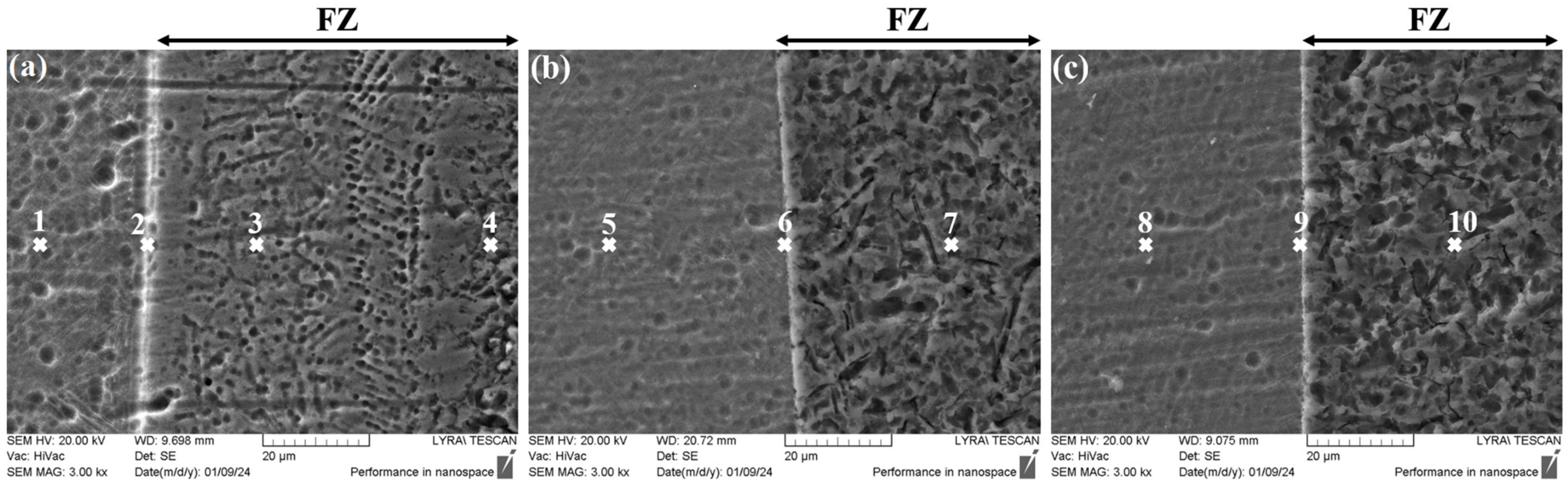
Figure 6a,
Figure 6b and
Figure 6c present high-magnification images of samples A, B, and C, respectively. The points studied using EDX are marked using an “ × ” and a consecutive number. The results of the analysis are summarized in
Table 2. It is important to mention that in the case of the titanium and aluminum alloys, for ease of interpretation, the alloying elements were excluded from the presented results. The percentile relative error of the given values is also indicated. As suggested by the macrostructure, a formation of intermetallic phases is present in the case of sample A at the border between the two alloys and also in the weld seam. The results of the EDX analysis suggest that it is possible that the Ti
2Al phase (according to the binary phase diagram [
27]) has formed at the border between the two materials and the TiAl phase has formed in the weld seam. Studying zones closer to the outer edges of the plates reveals the standard composition corresponding to the Ti6Al4V and the Al6082-T6 alloys. Samples B and C both show no signs of intermetallic compounds forming in the weld seam or at the border between the two materials.
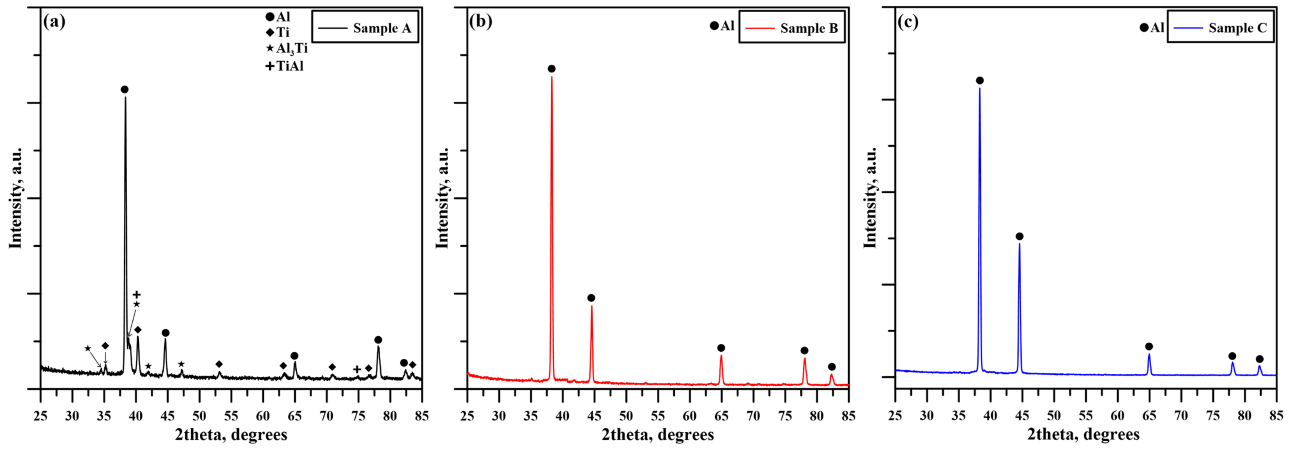
The results of the X-ray diffraction experiments are shown in
Figure 7. During all experiments, no amorphous-like halos were observed. No special preferential texture can be observed. All diffractograms shown in this study were obtained in the middle of the fusion zones of the corresponding samples.
Figure 7a presents the diffractogram obtained by studying sample A. The highest diffraction maxima correspond to the aluminum phase for two reasons—the high reflectivity coefficient of aluminum and its high content in the weld seam. Additionally, an α-Ti phase was detected along with a number of intermetallic compounds such as Al
3Ti and AlTi. Of course, the possible presence of other intermetallics that cannot be detected by the XRD method is not excluded. The results regarding the weld seams formed while preparing samples B and C both show no diffraction maxima other than those of the aluminum phase. In all cases, the aluminum phase had a face-centered cubic (fcc) structure, and the α-Ti phase had the characteristic of a hexagonal closed-packed (hcp) structure. The diffraction maxima were determined after comparing the obtained values to the ones presented by the International Center for Diffraction Data in power diffraction files (PDFs) #040787, #050678, #371449, and #441294.
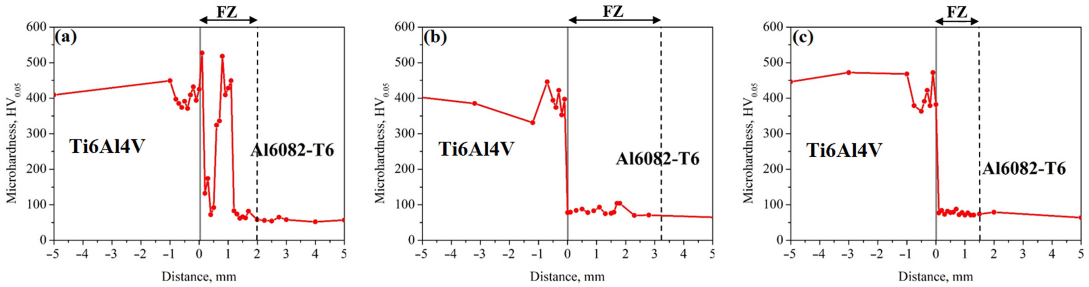
As mentioned, the microhardness of the samples obtained in this work was measured 1 mm and 3 mm below the surface of the samples. The microhardness of sample A 1 mm below the surface is shown in
Figure 8a. The highest microhardness value of this sample was 518 HV. Evidently, there are a number of drops in the microhardness values in the zone corresponding to the weld seam close to the 0 mm reference point. The microhardness values of samples B and C are shown in
Figure 8b and
Figure 8c. A slight increase in the microhardness is observed in the weld seam area; however, the values are highly comparable to the ones obtained for the Ti6Al4V plates. A rapid drop in the microhardness levels is observed, and the results obtained in that region correspond to the microhardness of the aluminum alloy.
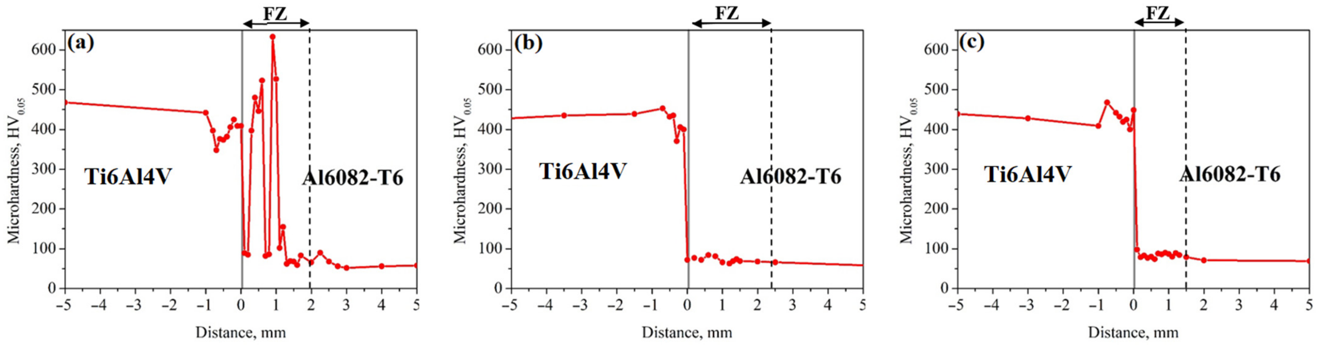
The microhardness taken 3 mm below the surface of the samples is shown in
Figure 9. Studying sample A (
Figure 9a) once again showed that in the fusion zone, the microhardness increases beyond that of the Ti6Al4V plate with a maximum value of 633 HV. Comparatively, samples B and C (
Figure 9b,c) showed the same trend as in the previous results, where the microhardness does not exceed significantly (or at all) that of the Ti6Al4V plate, and in the fusion zone, the microhardness corresponds to the microhardness of the Al6082-T6 alloy. Of course, an increase in the overall hardness is observed in all cases. The microhardness of as-delivered Ti6Al4V samples was measured and reported by Srivatsan et al. [
28] to be about 330 HV. Similarly, during their investigations, Jebraj et al. [
29] reported a microhardness of 95 HV for as-delivered Al6082-T6 aluminum alloy samples. In the present work, in all cases, a microhardness of over 400 HV was observed for the Ti6Al4V plate, and a microhardness in the range of 50–80 HV was observed for the Al6082-T6 plate side, in the fusion zone of course. Chai et al. [
30] surface-treated Ti6Al4V sheets using a pulsed laser device and reported an increase in the microhardness of the alloy in the treated zone. This is attributed to a change in the structure of the alloy due to a reduction in the size of its crystals, thus increasing its density and reducing the mobility of defects. These results are in agreement with the ones of this work, suggesting that both the preheating to 300 °C and the heat applied by the electron beam led to the increase in the microhardness of the Ti6Al4V plate. Comparatively, the microhardness of the aluminum plate was reduced significantly. The Al6082-T6 alloy is T6 heat-treated meaning, that the Al6082 alloy was solution-treated, heat-treated, and finally quenched in this specific pattern for different (predetermined) treatment times. During this process, a specific order of the structure of the aluminum alloy is formed which results in its strengthening. The application of any subsequent heat beyond 250 °C to heat-treated alloys as proven by Woelke et al. [
31] leads to a disruption of the order of the aluminum structure and a major reduction in its mechanical properties. Any heat treatment processes applied to the material prior to it being heated are reversed.
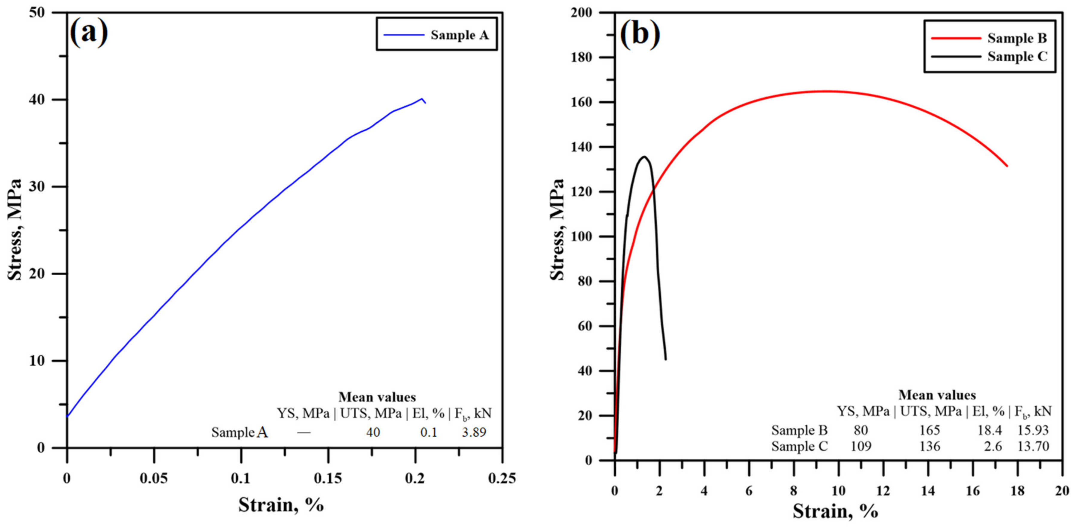
Following the microhardness experiments, tensile tests were performed in order to determine the mechanical strength of the formed joints. The results are summarized in
Table 3. The specimens corresponding to sample A broke nearly immediately. Due to this, a yield strength (YS) could not be determined as the stress–strain curve had a linear character. An average ultimate tensile strength (UTS) of 40 MPa was registered before the samples broke at an average breaking force F
b of 3.89 kN. Obviously, major defects were present in the weld seam of that sample in the longitudinal direction, resulting in a major decrease in the test area and thus the weakening of the joint. Furthermore, as proven by the EDX results for that case, intermetallics were detected, which possess high hardness [
32]. Their presence in the structure of a weld joint results in an increase in the joint’s brittleness [
33], which also leads to a worsening of the mechanical properties. The stress–strain curves of samples B and C are shown in
Figure 10a, and the obtained UTS values of the samples are compared in
Figure 10b. Sample B apparently had the best mechanical properties of the three. An average yield strength of 80 MPa was measured, along with an average UTS of 165 MPa. The elongation of those samples reached an average value of 18.4%, which indicates that those samples have good plasticity [
34]. It is important to note that when considering sample B, the fractures of the tensile test samples formed far from the weld seam, indicating that this sample has a strength surpassing that of the aluminum alloy. The formation of a brittle weld between similar and dissimilar metals using highly concentrated energy sources such as electron beams is a proven trend, and it results in a major reduction in the ductility of the output product, as proven by [
35]. Applying an offset to the electron beam towards the aluminum side has resulted in the formation of a more brittle joint. Despite this, the formed weld has satisfactory mechanical properties, and in some instances, low elongation and rapid breaking are preferred as opposed to a high affinity for plastic deformation.
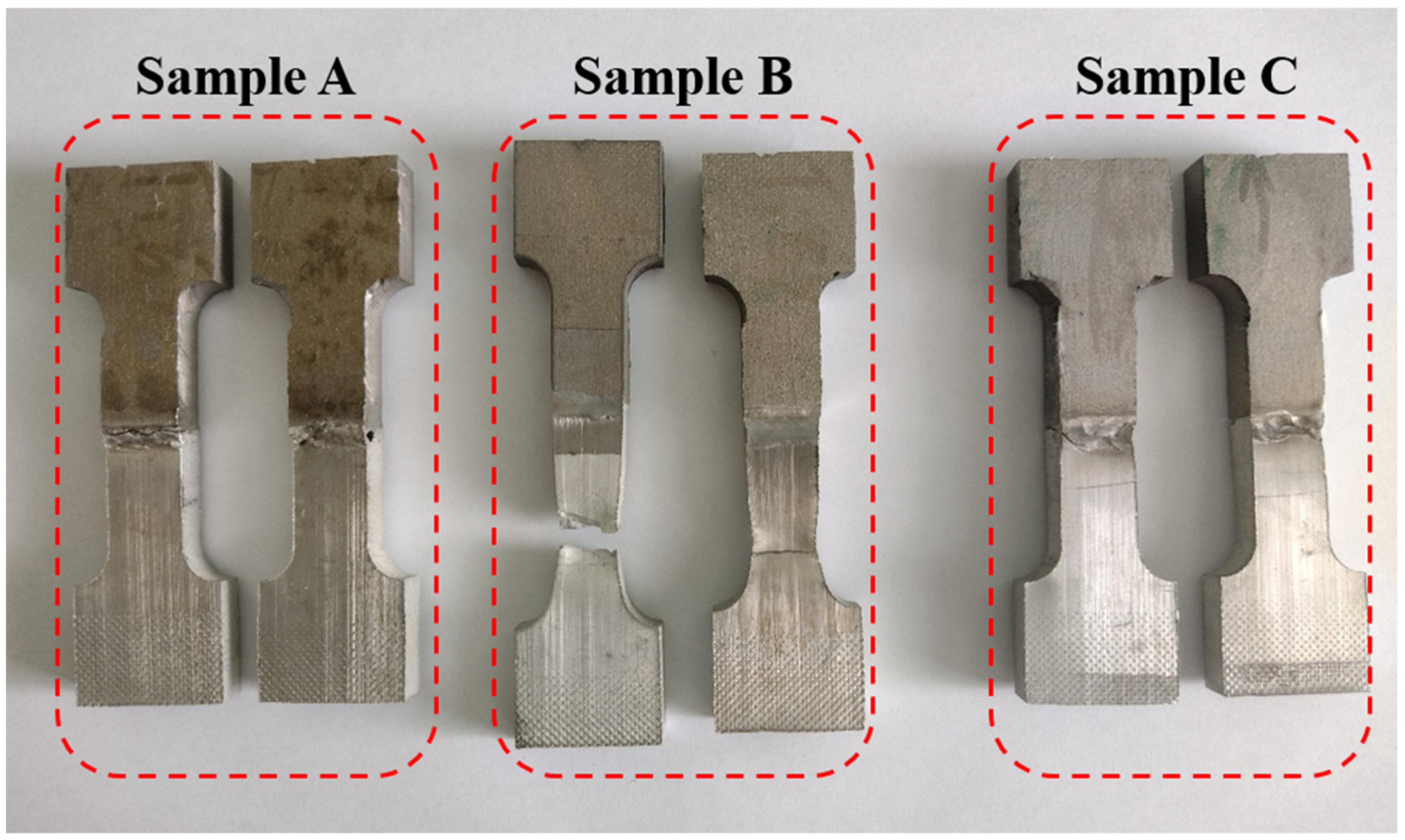
Figure 11 shows an image of the tensile test samples obtained during the present work. Evidently, in the case of sample A and sample C, the fracture of the samples occurred in the area corresponding to the weld seams. In the case of sample B though, the fracture occurred far from the weld seam in a zone belonging to the aluminum plate.
4. Discussion
As it is widely known, the physical process of electron-beam welding involves a highly focused flux of electrons that bombard the target material(s). During the interaction between the electrons and the target material, the energy of the electrons is dispersed in the volume of the target material. This is exactly the reason why the isotherms of the temperature fields are highly concentrated at the zone of contact between the material and the electron beam and dissipate along the depth of the contact zone. As a result, the “keyhole” weld seam typical for electron-beam welding is formed. There are instances, however, when the technological conditions during the welding process are such that the energy generated is too high, resulting in the full penetration of the electron beam (even distribution of the isotherms).
In the present case, concerning sample A, full penetration was achieved due to a number of reasons. Firstly, applying heat to all samples in advance excited the particles of the plates which facilitated the process of interaction between the electrons and the solid-state material. In addition, sample A was prepared using a high beam current. The results of this choice of technological conditions were as follows: Applying such a high current led to the rapid uncontrollable melting of both the aluminum and the titanium plates. As a result of this, a high quantity of intermetallic compounds formed in the fusion zone, reducing the ductility of the weld. Due to the high welding speed, the distribution of the formed molten pool was unstable, leading to uneven miscibility and cooling of the formed molten pool. Exactly during the cooling process, due to the unstable recrystallization of the molten pool, major defects in the form of blow holes formed, accompanied by large pores within the fusion zone itself. During the electron-beam irradiation of the plates, since aluminum is a much more thermally conductive material, the temperature was mostly dissipated through its volume. As a result, overheating of the aluminum plate occurred, and an accelerated process of aluminum vaporization was noticed. This also highly contributed to the formation of blow holes in the border between the aluminum plate and the fusion zone. It is important to notice that despite the unstable process, no cracks or gas pores were detected.
The process of EBW was significantly improved by the utilization of a slow welding speed and a low current of the electron beam. As previous authors have proven, the application of a lower welding speed results in the formation of a larger weld seam [
36]. Due to the applied preheating and the significantly lower melting temperature of the aluminum alloy, most of the energy of the electron beam was dissipated precisely in the aluminum plate. A minimal amount of the titanium plate (if any) was molten during the process. Due to this, no intermetallic compounds were formed. Evidently, this resulted in a major improvement in the ductility of the weld. Due to the controlled and equilibrated welding process, both physically and thermally, no defects were formed within the weld seam (such as pores or cracks) or at the edge between the two materials. Interestingly, no heat-affected zones were detected during any of the welding processes, indicating that the heat generated was most probably almost evenly dissipated through the materials (preferentially through the aluminum plate). This was assisted artificially by the preheating of the plates. The formed weld in the case of sample B showed the best mechanical properties compared to the others. The maximum UTS of this sample achieved in this work is slightly higher compared to that achieved in a previous investigation [
22], but the most important improvement was the increase in ductility, which compared to the most successful sample in the previous work was over 80%. This improvement is attributed to the excellent mechanical characteristics of the weld seam. As mentioned above, the fracture during the performed tensile tests in the case of sample B occurred far from the weld seam and closer to the outer edge of the aluminum plate. This indicates two things. First of all, the weld seam showed excellent strength and successfully withstood the performed tensile tests. Secondly, due to the uniform distribution of the thermal fields, aided by the performed preheating of the samples, no obvious heat-affected zones were noticed. Commonly, it is exactly within the heat-affected zones where fractures occur during tensile testing regardless of the applied welding method.
Typically, a common solution to issues such as poor miscibility, poor (or uncontrollable) weld pool formation, or high formation of intermetallics is the offsetting of the electron beam (laser beam) towards the aluminum side [
37]. In most cases, this indeed is a viable strategy that improves both the structure and the mechanical properties of the joint [
37]. In the present case, such a strategy was also investigated despite the successful formation of a strong weld without the offset. Initially, while the temperature of the plates was gradually increasing, the weld seam formation was highly uniform, and once the plates’ temperature started increasing, the temperature dissipation of the plates was reduced significantly, resulting in the formation of “overheating” zones. This broke the uniformity of the process and led to a change in the dimensions of the weld seam. Most importantly, due to the already heated plates, the power of the electron beam in this particular case was sufficient in order to fully penetrate the plates (particularly the aluminum one) and to form a weld seam with a rectangular-like shape as in the case of sample A. Due to the overheating of the aluminum plate, droplets of aluminum were found underneath the weld seam. Despite this, due to the theoretical reduction in the residual stresses achieved through the preheating of the plates, no major defects were detected in sample C (pores, cracks, or others). Regardless, due to the lower quantity of molten aluminum and due to the uneven process of weld seam formation, this sample achieved good mechanical strength in the form of UTS; however, similarly to other samples formed in previous experiments, it was proven to be brittle.
In summary, the results of the current work indicated that high-strength bonds between a Ti6Al4V alloy and an Al6082-T6 alloy can be formed by using two different approaches: either by carefully selecting an optimal offset towards the aluminum plate, which has proven to be a difficult task, or by preheating the plates. Weglowski et al. [
38] show that preheating of the plates can also be achieved using the electron beam in a high-vacuum environment. This could theoretically reduce any possible contaminants on the welding surfaces and thus in the fusion zone itself. In the present work, it was proven that external heating of the substrates can also be employed to reduce residual stresses (mostly in the form of thermal residual stresses) and also to reduce the possibility of the formation of cracks along the length of the weld. Preheating also negates the necessity of applying a beam offset in either direction. Of course, this is another technological step that needs to be organized and performed before each welding procedure, which could increase manufacturing costs. However, it must be mentioned that this would also lead to an improvement in the quality of the output product. Lastly, a future study could be useful indicating the influence (if any) of the preheating temperature on the resultant structure and mechanical properties of the formed weld seams.


 ,
, 


