Article

Effect of Corrosion and Post-Weld Treatment on the Fatigue Behavior of Multipass Robot GMAW Welds of S700MC Steel

by
Stefania Spyropoulou
,
Emmanouil Christofilis
and
Anna D. Zervaki
*
Shipbuilding Technology Laboratory, School of Naval Architecture and Marine Engineering, National Technical University of Athens, Zografou, 157 80 Athens, Greece
*
Author to whom correspondence should be addressed.
Crystals 2024, 14(7), 609; https://doi.org/10.3390/cryst14070609
Submission received: 10 June 2024 / Revised: 25 June 2024 / Accepted: 27 June 2024 / Published: 30 June 2024
(This article belongs to the Special Issue Corrosion Phenomena in Metals)

Abstract

:
High-strength steel is a candidate material for offshore structures, which are currently being constructed with regular-strength steel. These structures are constantly exposed to harsh environmental conditions and experience cyclic loadings, which can lead to premature failure due to the synergistic effects of corrosion and fatigue. In this regard, the current study aims to investigate the effects of corrosion and High-Frequency Mechanical Impact (HFMI) treatment on the fatigue behavior of welded joints made of S700MC steel. Multipass butt-welded joints were fabricated via the Robot GMAW method at an optimally selected heat input of 0.7405 kJ/mm. The microstructure of the weldments was studied using light optical microscopy. Tensile and Vickers microhardness tests were performed to evaluate the mechanical properties of the welded joints. To simulate marine environment corrosion in the laboratory, the as-welded samples were exposed to salt fog spray for 720 h. Subsequently, specimens were subjected to cyclic loading to evaluate their fatigue strength, while SEM and stereomicroscopy were used to analyze the fractured surfaces, providing a comprehensive understanding of the fracture mode. The findings suggest that although corrosion led to increased surface roughness and the formation of corrosion pits, its influence on the fatigue behavior of the weldments might be less significant compared to other geometrical factors, at least for the exposure time employed in the study.

1. Introduction

Over the past few decades, significant progress has been achieved through thermomechanically controlled processing (TMCP), which allows for the cost-effective manufacturing of high-strength low-alloy (HSLA) steels, eliminating the requirement for quenching and tempering or the use of high alloying contents. TMCP includes heating the steel slab between 1200 and 1300 °C, followed by controlled rolling at different temperature ranges, depending on the desired microstructures and mechanical properties [1,2]. These developments have resulted in the production of HSLA steels with a fine grain size, effectively combining high strength (up to 1000 MPa yield strength (YS)) with excellent toughness, improved weldability and corrosion resistance [3,4,5,6]. For the above reasons, HSLA steels are used in a wide variety of applications, in particular as structural components, pressure vessel materials, gas/oil transportation pipelines, shipbuilding materials, offshore constructions and automotive components [4,7].
HSLA steels are classified as low-carbon steels (C < 0.20 wt.%) [8] and achieve their high strength levels through very low concentrations (generally less than 0.1 wt.%) of grain refining alloying additions (mainly V, Nb, Ti) [1,4,8,9], leading to precipitation hardening or grain refinement strengthening mechanisms facilitated by TMCP. Grain refinement—combined with TMCP—leads to a notable increase in strength while also having a positive effect on toughness [10]. Their microstructure is mostly ferritic with a small amount of pearlite [8,9], while various morphological variations of ferrite, including acicular (αα), Widmanstätten (αw) and allotriomorphic (α), are observed in HSLA steels. Depending on the desired mechanical properties, there may be variations resulting in non-equilibrium phases in the microstructure, such as bainite or martensite [3,8,11]. The specific variant of ferrite is determined by factors such as the γ→α transformation temperature, the cooling rate and the size of the austenitic grains [1,12]. More specifically, the existence of acicular ferrite is consistently connected to the microstructure of welds, owing to the presence of non-metallic inclusions, which act as preferable nucleation sites [8,12], and it is generally considered a highly desirable microstructural constituent [13]. It is worth mentioning that in multipass steel weld deposits, each pass undergoes additional thermal cycles due to the deposition of subsequent layers, leading to phase transformations [1].
Welding stands out as a fundamental manufacturing process in the construction and manufacturing sectors; thus, the weldability of HSLA steels has become crucial in evaluating the viability of welded structures [5]. Conventional arc welding techniques, such as Gas Metal Arc Welding (GMAW), are the most common methods used in the industry for joining HSLA steels [7], involving the construction of ships, maritime structures and offshore platforms [14]. GMAW is a cost-effective and time-saving welding method, owing to its high deposition rate, while its flexibility allows for the connection of a wide range of metallic materials with varying dimensions. In GMAW, an electric arc is generated between a filler wire electrode and the workpiece metal. The electric arc generates heat between the two parts, resulting in their fusion and the formation of a joint. The molten metal pool is protected against atmospheric contamination and oxidation via shielding gas, which is fed through the welding gun [15]. However, GMAW involves high heat inputs, leading to low cooling rates of the weldment. This, in turn, can cause softening of the Heat-Affected Zone (HAZ), resulting in low strength of the welded joints, especially for TMCP fabricated steels [5,6,7,16,17]. Additionally, the HAZ can act as a nucleation site for cracking, due to the generation of residual stresses [16]. Amraei et al. [18] studied the effect of heat input on the mechanical properties of ultra-high-strength steel joints. Softening of the HAZ was observed, which was attributed to phase transformations that took place during the welding, leading to different microstructural constituents between the HAZ and base metal (BM). Similarly, Hochhauser et al. [17] noted a decrease in hardness within the HAZ in the case of TMCP steel. This reduction appears to be related to either the thickening of precipitates or the rearrangement of dislocations (recovery) in regions of the HAZ subjected to temperatures below A1. Nevertheless, the decrease in hardness within the HAZ is not necessarily an indication of an overall deterioration of the mechanical properties, as the width of the HAZ should also exceed a critical value [16,17].
For critical applications, such as offshore structures, there is great susceptibility to fatigue failure, as a result of components being subjected to cyclic loading during their operation. Fatigue is the most common failure mechanism in weldments, as the area around the toe of the weld is often the prime location of crack initiation, due to increased residual stresses introduced by geometrical variations of the weldment [5]. Understanding this failure mode seems to be even more critical in welded high-strength steels, as the fatigue life of welds does not proportionally increase with mechanical strength [6,19], and the effect of notches becomes more detrimental [20]. The fatigue strength is substantially influenced by key factors, including the geometry of the weldment, surface roughness, microstructure of HAZ and weld metal (WM), residual stresses introduced by the welding process and metallurgical flaws [5,21]. Costa et al. [6] noted a considerable enhancement in fatigue strength after the removal of weld reinforcement in high-strength steel butt welds with a YS of 670 MPa. Instead, in such cases, crack initiation sites can be discontinuities of the weld, such as pores, slag inclusions, the presence of undercut and areas with incomplete penetration [5,21]. Lahtinen et al. [5] reported that S700MC steel weldments subjected to varying heat inputs exhibited a decline in fatigue strength compared to BM. This reduction in fatigue strength is more profound at lower cooling rates, which was attributed to a wider HAZ with a lower average hardness, both consequences of the increased heat input. In their investigation of S460MC steel fillet welded joints, Moravec et al. [19] identified a trend towards improved fatigue resistance (up to 30%) in high-cycle-fatigue areas with lower heat input (8 kJ·cm−1). However, they claim that the weld’s geometric design remains the primary factor governing fatigue behavior.
In addition, corrosive environments have a negative impact on the mechanical properties of materials, including the reduction in fatigue strength, increasing surface roughness and contributing to the premature initiation of cracking under equivalent stresses. Welds typically exhibit lower corrosion resistance compared to the BM, a phenomenon influenced by various factors inherent to the weldments, including the microstructure, chemical composition and the existence of residual stresses [22]. Metallurgical factors play a significant role in influencing corrosion behavior, as referenced in [23]. Welds are particularly prone to galvanic corrosion, pitting corrosion, stress corrosion cracking, intergranular corrosion, hydrogen embrittlement cracking and corrosion fatigue [24]. The existence of corrosion pits on the surface is known to act as a potential initiation site for fatigue failure [25]. Preferred sites for pit formation are microstructural imperfections, including non-metallic inclusions and grain boundaries. Ahn et al. [26] conducted fatigue tests on cold-rolled and pre-corroded HSLA steel specimens. They observed that in the case of pre-corroded samples, fatigue cracking was initiated on corrosion pits, which act as stress concentration notches, while a reduction in fatigue life was also noticed. In their investigation, Gkatzogiannis et al. [25] revealed that even a short exposure period (10 days) of welded S355J2+N structural steel in a simulated saltwater environment (salt fog spray test) resulted in a significant deterioration of surface characteristics and a subsequent reduction in fatigue resistance. The study emphasizes that corrosion not only causes material loss but also alters the weld’s geometrical characteristics, ultimately leading to a detrimental effect on its ability to withstand cyclic loading. Furthermore, the presence of corrosion pits on the surface introduces potential initiation points for cracks, further reducing the fatigue strength of the weldment. Knysh et al. [27] observed an 11% reduction in fatigue strength in pre-corroded (1200 h exposure in salt spray) weld specimens made of steel with a YS of 400 MPa. Similarly, Gkatzogiannis et al. [28] conducted fatigue tests on S355NL steel weld specimens pre-corroded via salt spray (60 days) and observed an 18% reduction in fatigue strength, attributed to the acceleration of the crack initiation stage.
Post-treatment methods enhance the fatigue strength of welded high-strength steel joints significantly. In 2010, Commission XIII introduced the term High-Frequency Mechanical Impact (HFMI) as a generic term to describe several related technologies for improving the fatigue strength of welded structures by locally modifying the residual stress state using ultrasonic, pneumatic or other technology [29]. This method involves a hardened metal pin hammering onto the weld toe surface with high frequency and causing local plastic deformation in this area. The weld toe geometry is rounded out; this reduces the notch stress concentration, beneficial local compressive residual stresses are induced, the top surface layer is hardened due to the local cold forming and small welding-induced cracks on the surface are closed [30]. Studies show that crack propagation velocity is affected as cracks up to a depth of 1 to 2 mm grow much slower in HFMI-treated welds [31]. The magnitude of improvement in fatigue strength of variable amplitude loading may differ from that of constant amplitude [32]. The reason for this is that under spectrum loading, higher load levels lead to a more severe reduction in compressive residual stresses than under constant amplitude loading.
S700MC is a high-strength steel, characterized by low carbon and low alloy content. It is produced through TMCP, with a nominal yield strength of 700 MPa, and is commonly used in the manufacturing of heavy lifting equipment and the transportation industry (particularly in structural components of vehicles such as car and truck chassis frames and wagon parts) [7,33,34]. In the present work, the influence of pre-corrosion and the enhancement of HFMI on the fatigue behavior of multipass automatic (Robot) GMAW welding is investigated. The experimental procedure involved testing sixteen welded joint specimens of S700MC under cyclic loading, with six in the as-welded (AW) condition, five in the pre-corroded (C) and five in the HFMI-treated condition. Corroded weldments were exposed to a simulated saltwater environment (salt fog spray test) for 720 h. Additionally, fractographic examination of the cracked region was carried out for chosen fatigue-cracked specimens, providing valuable insights into the initiation and propagation of fractures.

2. Materials and Methods

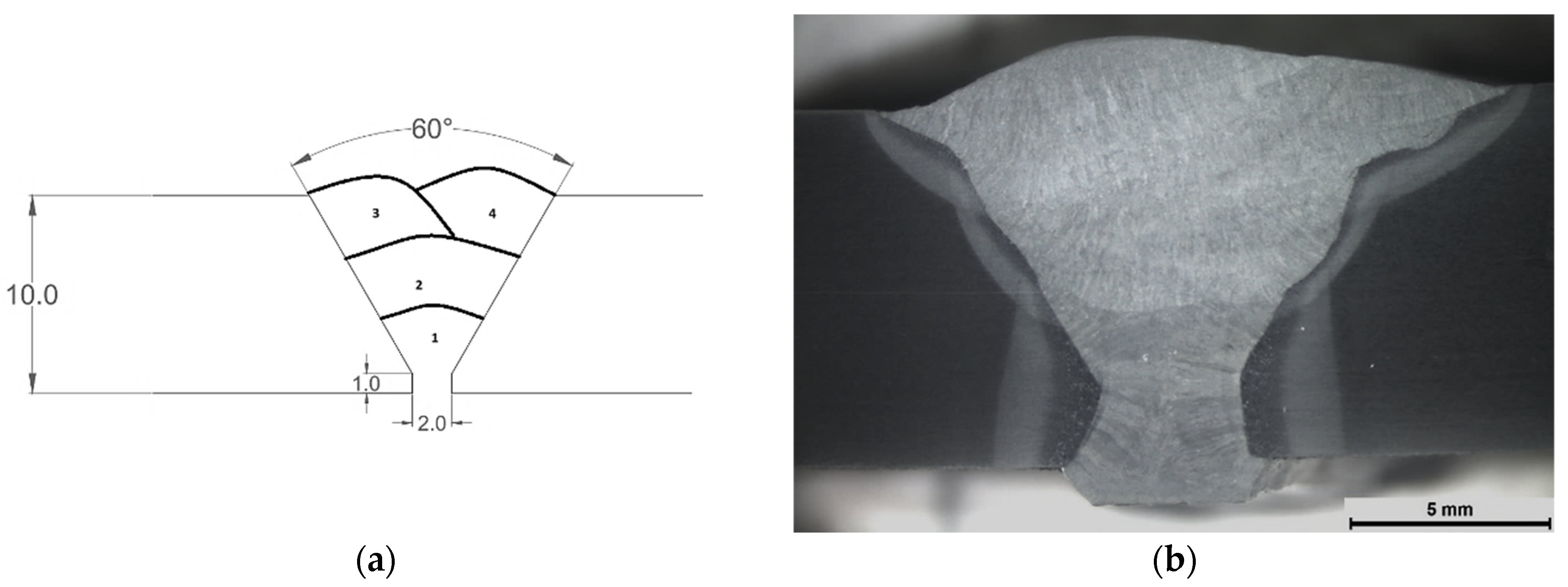
2.1. Materials and Welding Procedure

S700MC was provided by SSAB EMEA AB (Stockholm, Sweden), and butt joints were formed via an automated GMAW welding process by the use of a “KAWASAKI” robotic arm, coupled with a “FRONIUS” welding machine (model FK 4000-R) provided by VETA S.A. (Acharnes, Attiki, Greece) with M21 shielding gas (18% CO2 + Ar). OK AristoROD 69 (EN ISO 16834-A: G Mn3Ni1CrMo) [35] solid wire with a 1.2 mm diameter was used as filler metal. The nominal chemical compositions for the BM and the filler metal are given in Table 1. The YS, ultimate tensile strength (UTS) and elongation (A%) in the transverse direction of S700MC steel, as provided by the manufacturer, are σy (min.) = 700 MPa, σUTS = 750–950 MPa and A% (min.) = 12%.
Prior to welding, a V-shaped groove with a 60° angle and a root face with a thickness equal to 1.0 mm were machined on the steel plates, followed by a thorough cleaning of end surfaces using acetone to eliminate any organic contamination, dirt residues or grease. Each plate was measured to be 340 mm × 120 mm, with a thickness of 10 mm. Four passes were conducted for each weldment, while each pass was performed with the same heat input, which was defined by the standard EN 1011-1 [37]. Three welds were fabricated under controlled, identical conditions following the welding process parameters outlined in Table 2, as established by N. Daskalopoulos’ diploma thesis [38]. In addition, a ceramic backing strip was used during the welding process and a distance of 2 mm (root opening) was sustained between specimens. The dimensions and configurations of butt welds, along with the welding sequence, are illustrated in Figure 1. Three welds were fabricated under controlled identical conditions.
Weldment inspection was conducted to verify the absence of porosity or other metallurgical flaws (cracks, inclusions) in the welded joints. For this purpose, several non-destructive tests (NDTs), such as visual inspection, liquid penetrant testing, magnetic particle inspection and ultrasonic testing, were performed on the as-welded plates. Weld quality verification (geometrical evaluation of joint) was carried out according to EN ISO 5817 [39] and EN ISO 6520-1 [40].

2.2. Metallographic Observations

Microstructural and macrostructural analyses were conducted on cross-sections that were cut, ground, polished down to 1 μm particle size and etched using 3% Nital solution for 10–15 s using the “Leica DM ILM” light optical microscope (LOM) and “LeicaMZ6” stereomicroscope (Leica Microsystem, Wetzlar, Germany). Metallographic characterization was carried out on the BM, HAZ and welded zone, and their microstructural features were observed.
Microhardness measurements were performed using a digital Vickers microhardness tester (Wolpert-Wilson 402 MVD, Wolpert Wilson Instrument, MA, USA) with an applied force of 300 gf (HV0.3) and a dwell time of 10 s. The distance between adjacent points in microhardness measurement was 0.1 mm, along three longitudinal directions, on the centerline of the specimens, as well as distanced 2 mm from their upper and lower surfaces, in accordance with ISO 6507-1 [41]. This approach enables the identification of different zones (HAZ, BM, WM), along with the sub-zones within the HAZ, i.e., coarse-grain HAZ (CGHAZ) and fine-grain HAZ (FGHAZ), for microstructural analysis.

2.3. Corrosion Tests

Prior to corrosion tests, the surface of the specimens was prepared in a process that included degreasing in an ultrasonic bath containing ethanol. The samples were subsequently weighed using an electronic analytical balance [42]. Corrosion tests were performed by exposing the welded joints in a salt fog spray chamber according to ASTM B117 [43], using a Q FOG CCT 1100 salt spray testing machine (Q-Lab Corporation, Westlake, OH, USA) The salt spray tests were conducted under the following conditions: 50 g/L concentration of NaCl (5% NaCl) and temperature at 35 °C ± 2 °C. The samples were placed at an angle of 20° from the vertical axis inside the chamber and subjected to the aforementioned corrosion conditions for 720 h. The corrosion resistance was evaluated using the weight loss method following EN ISO 7539-1 [44], a standard procedure. The corrosion rate (CR) (in mm/year) of the steel samples exposed to a 5% NaCl solution for specific periods of exposure was determined using the weight loss method (Equation (1)).
C R m m y e a r = K × W A × T × D
where K is the conversion factor (equal to 8.76 × 10⁴), W is the mass loss of the steel specimen (in g), A is the exposure area of the specimen (in cm2), T is the exposure time (in hours) and D is the density of the metal (equal to 7.86 g/cm3). The exposure area of each specimen was determined using Equation (2).
A = 2 [ L W + L H + W H ]
where L is the length of the specimen (in cm), W is the width of the specimen (in cm) and H is the thickness of the specimen (in cm).

2.4. HFMI Treatment Procedure

Prior to HFMI treatment, the weld cap and adjacent parent material were fully de-slagged and wire brushed or ground to remove all traces of oxide, scale, spatter and other foreign material [29]. Commonly, HFMI is applied on the weld’s toe. For the purpose of this experiment, V groove welds were used. In order to avoid fracture near the root due to unwanted residual stresses, the HFMI device (Figure 2) was applied both on the weld’s toe and root. The parameters of the test are exhibited in Table 3.

2.5. Tensile and Fatigue Tests

Tensile and fatigue tests were conducted at room temperature using the MTS 647 hydraulic (MTS system, Eden Prairie, MN, USA) wedge grip tensile test machine. For each of the experiments, the standards EN ISO 6892-1 [45] and ASTM E468-18 [46] were used. The tensile specimens were dimensioned according to recommendations in ASTM E 8M-04 [47], while fatigue specimens were machined based on the ASTM E466-96 standard [48]. For both tests, the weld was located in the middle of the specimen gauge length.
Tensile tests were carried out with a strain rate equal to 2 mm/min, while an extensometer was fixed on the gauge length of each specimen (value of gauge length equal to 50 mm) to measure the axial strain during the experiment. The tests were conducted in order to determine the YS and UTS of the weldment, in the AW condition, along with the position of the fracture. Fatigue testing was conducted under constant amplitude load control in tension with stress ratio R = 0.1 and at a loading frequency of 5 Hz on pre-corroded (C), AW and HFMI specimens for comparison. Prior to tensile and fatigue tests, the welded specimens underwent surface finishing (grinding) to smooth out any irregularities that resulted from the cutting process and therefore to reduce the influence of the notch effect [33]. Specimens were subjected to various stress levels corresponding to different percentages of the yield strength: 85%, 50%, 40%, 30%, 25% and 20%. In this respect, specimens were labeled according to the condition, followed by the stress they were subjected to (e.g., AW85—as-welded specimen, tested for fatigue at 85% of the YS).

2.6. Characterization of Fractured Surfaces

An analysis of fractured surfaces was conducted to obtain a comprehensive understanding of the fracture. This analysis aimed to determine the fracture sequence, identify the fracture origin and detect any macroscopic features relevant to fracture initiation or propagation. Initially, the fracture surfaces were visually examined. Subsequently, the surfaces underwent further examination at higher magnification using a “LeicaMZ6” stereomicroscope and a JSM 6390 scanning electron microscope (JEOL Ltd., Tokyo, Japan).

3. Results and Discussion

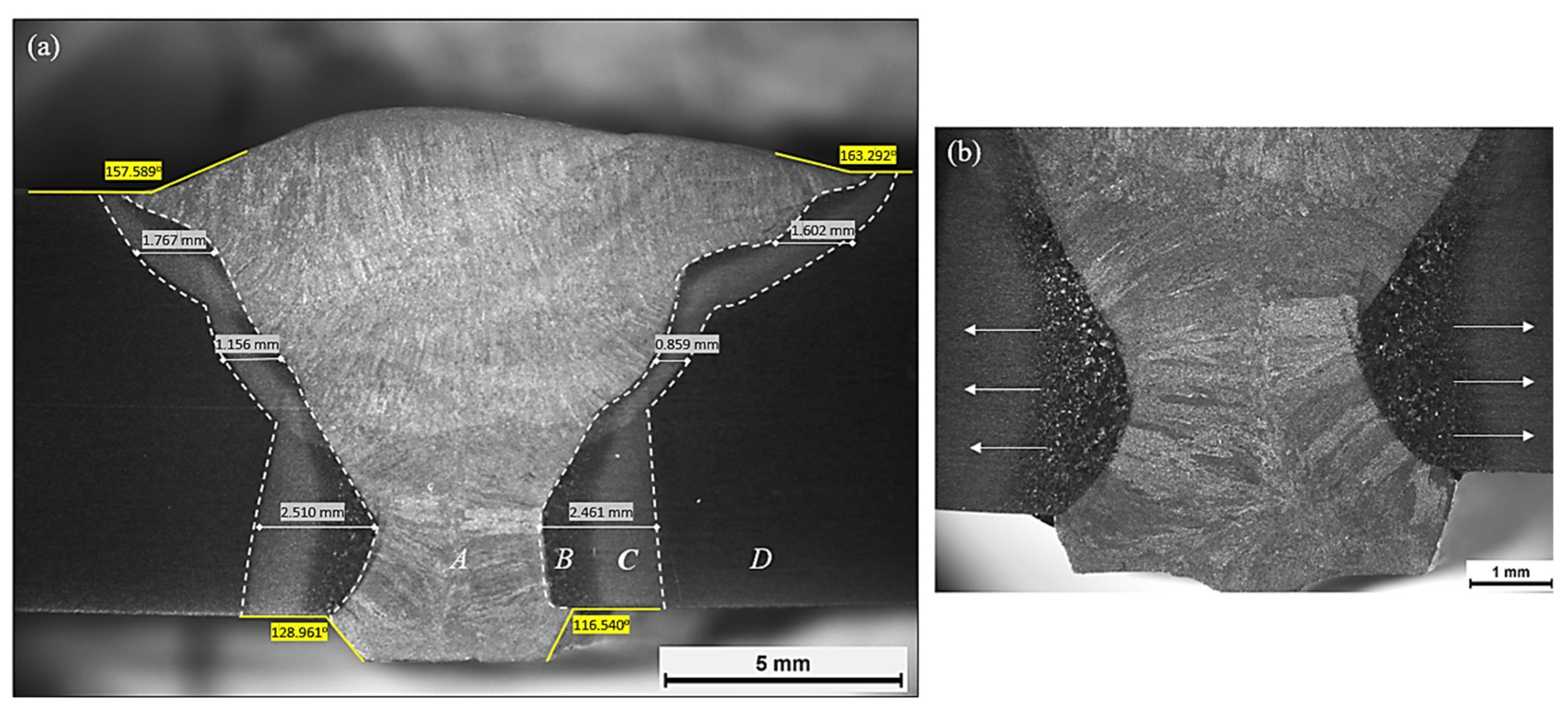
3.1. Macrostructural Examination

No cracks or other surface deformities were observed through visual examination. Furthermore, liquid penetrant inspection and magnetic particle inspection yielded no additional information regarding subsurface discontinuities. Despite the above-mentioned observations, ultrasonic testing revealed the presence of pores in certain regions of the weldments. Consequently, these areas were excluded, and machined specimens for tensile and fatigue tests were selected from the defect-free areas of the plates. The macrostructure of a typical weldment, which is depicted in Figure 3, indicates that a proper weld bead with complete penetration has been produced. An evaluation of geometric imperfections (such as excess weld metal, excessive penetration, incorrect weld toe, linear and angular misalignment) resulted in a level C quality assessment according to the EN 5817 standard [39].
The width of the HAZ decreases with each subsequent pass (Figure 3). Within the WM, a columnar microstructure is observed near the fusion line, and equiaxed grains can be seen at the center of the weld pool. The orientation of the dendrites aligns with the direction of heat flow. The first pass exhibits a considerably wider HAZ compared to subsequent passes, and excessive grain growth is observed within the CGHAZ as a result of the developing temperature field. After the deposition of the second pass, heat is conducted to the larger free surface, as well as towards the previous pass. This results in a reduction in both the width of the HAZ and the size of the CGHAZ grains in comparison to the first pass. Similar phenomena are observed with the deposition of the third and fourth passes. However, a slight increase in the HAZ width is noted. This can be explained by the shifted deposition location of these passes towards the edges of the plates, which results in a slightly higher proportion of heat flowing towards the BM compared to the second pass.

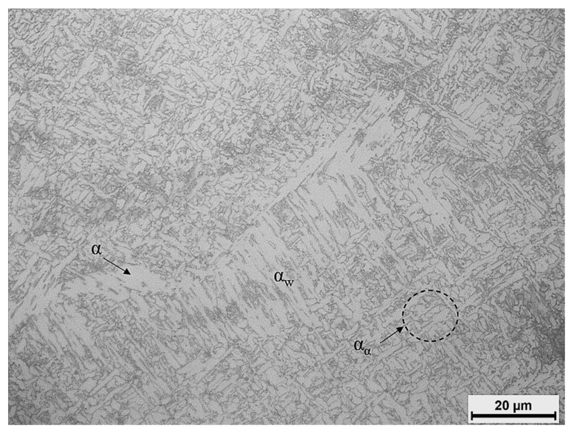
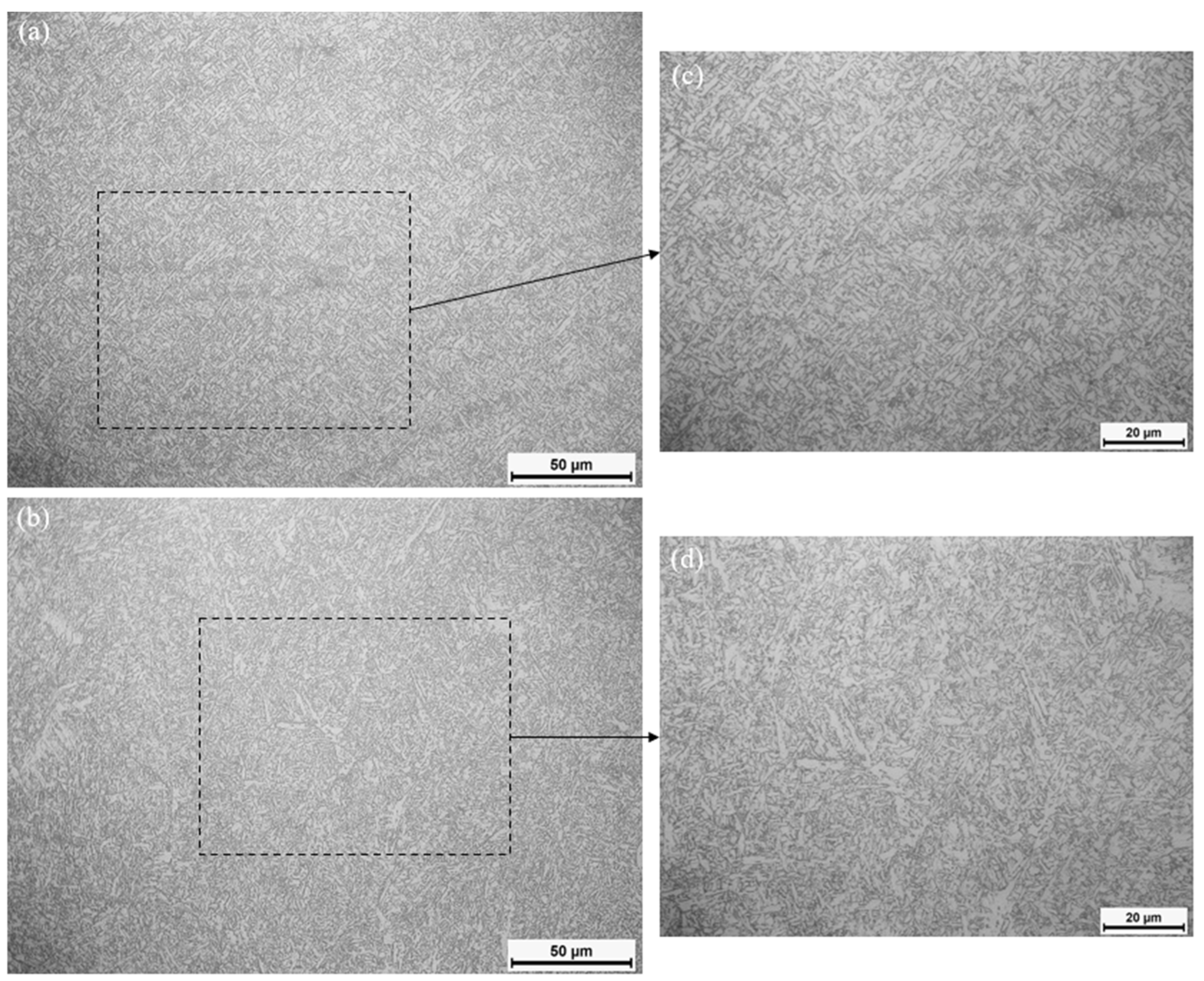
3.2. Microstructural Examination

Figure 4 shows the microstructure of the S700MC consisting of fine-grained ferritic grains, elongated following the rolling direction. In higher magnifications, equiaxed ferrite grains can also be seen. Despite the inhomogeneity observed in grain size, the mean grain size was measured to be 3.8 μm ± 0.9 μm, consistent with previous observations [33,49]. Various sources note the existence of small amounts of bainite in S700MC steel [50,51,52], although no bainitic structures were detected in the BM. The microstructure of the WM can be seen in Figure 5. Grain boundary ferrite (α) has formed on the prior austenite boundaries, as these regions are of higher energy, providing the driving force for nucleation. Widmanstätten ferrite (αw) nucleates from the grain boundary ferrite and develops towards the interior of the austenite grains in the form of elongated plates that grow in specific crystallographic directions. The interior of the austenite grains consists of a randomly oriented apolygonal ferrite microstructure, often referred to as acicular ferrite (αα). The formation of acicular ferrite inevitably results in the enrichment of neighboring austenite grains with carbon, leading to increased hardenability and regions of retained austenite, martensite or pearlite. Such areas can appear darker in micrographs, as they are affected more heavily by the etchant [53].
The plates of acicular ferrite appear fine-grained, which can be attributed to the low heat input (h = 0.7405 kJ/mm) employed during welding (Figure 6). This aligns with the principle that acicular ferrite growth depends on the diffusion of carbon atoms in austenite. The high cooling rate associated with low heat input restricts carbon atom diffusion, resulting in a finer-grained acicular ferrite distribution [54]. The width of the acicular ferrite plates changes from the first pass to the second, with the latter displaying coarser plates and a less uniform size distribution. This variation can be attributed to the different cooling rate for each pass. In the second pass, the lower cooling rate enhances carbon atom diffusion in the austenite, enabling the acicular ferrite plates to increase in width since their growth is governed by that factor. Additionally, the second pass shows a tendency for increased amounts of intergranular ferrite, likely due to the reduced cooling rate that enhances diffusion processes, such as the nucleation and growth of ferrite along the austenitic grain boundaries.
The HAZ consists of coarse ferrite grains and bainite close to the weld (CGHAZ) and finer ferrite grains with less bainite further away (FGHAZ). Figure 7 illustrates the microstructure of the GCHAZ. The size of the prior austenite grains reveals that grain growth has taken place within this zone. This grain growth reduces the austenite surface area per unit volume, consequently decreasing the number of available nucleation sites at the austenite boundaries. This reduction in nucleation sites contributes to increased hardenability of the steel, favoring the occurrence of non-equilibrium phase transformations. Within austenite grains, fine lath carbides/bainite have precipitated [55], as can be seen in Figure 7a. Nucleation of proeutectoid ferrite has occurred at grain boundaries, while at higher magnifications (Figure 7b), plates of acicular ferrite are found to nucleate intragranularly, presumably from non-metallic inclusions within the larger austenite grains. In contrast, the FGHAZ is characterized by a dominant presence of polygonal, near-equiaxed grains of proeutectoid ferrite (α) (Figure 8). This ferrite variant nucleates preferentially at prior austenite grain boundaries, and its growth proceeds via the diffusion of carbon. Dark etched regions observed at high magnifications may indicate the presence of bainite.

3.3. Mechanical Property Evaluation

The welding process of the S700MC steel results in a notable reduction in hardness (softening) inside the HAZ compared to the BM (Figure 9), consistent with previous findings [5,17,56]. Furthermore, a more pronounced decrease in hardness within the FGHAZ was observed, compared to the CGHAZ. While microhardness measurements across the weld appear symmetrical on either side of the centerline (x-axis = 0 mm), a deviation from this pattern is observed on the middle line. Notably, the microhardness of both the FGHAZ and CGHAZ is significantly higher on the side where the third weld pass is deposited. This phenomenon can be attributed to the shifted deposition—towards one plate side—technique commonly employed in multipass welds to fill the gap between the two plates. This results in a heterogeneous temperature distribution across the weldment, leading to variations in the metallurgical characteristics of the material, which can influence the mechanical properties of the weld. The BM shows an average hardness value of 288 HV0.3, which is consistent with the literature [5,51,52]. Although S700MC steel primarily features a ferritic matrix, its relatively high hardness can be attributed to several factors: (1) the reduction in grain size within the microstructure; (2) the presence of nanoscale precipitates, which enhance the hardness through precipitation hardening; and (3) the increase in dislocation density, as a result of rolling. Moreover, if any type of bainitic structure exists in the BM, then it may also contribute to the increased hardness. As for the WM, its average hardness value appears to be independent of the number of deposited passes, at approximately 278 HV0.3, which is slightly lower (by 3.6%) than that of the BM. Among the two HAZ sub-zones, the FGHAZ exhibits the lowest hardness value, regardless of the number of welding passes employed, owing to the presence of bainite in the CGHAZ, while the former consists mainly of ferrite. The reduction in hardness of the FGHAZ compared to BM is attributed to the elimination of the crystallographic texture and, consequently, the rearrangement of dislocations into lower energy configurations, rather than to phase transformations, even though recrystallization of the microstructure has occurred.
The microhardness evaluation at the HFMI weld is similar to the as-welded specimen. It is noted that on the upper line, there are some higher measurements, above 300 HV0.3, at the edge of the fusion zone. As a result, extra tests were provided in order to observe the microhardness closer to the notch created by the treatment. At a distance closer than 0.1 mm from the surface, the microhardness increased to 350–400 HV0.3. These results are compatible with other research. The increase is not that radical, due to the high-strength steel being tested. The surface hardness is expected to be increased even more in low-strength steels, as this phenomenon depends on the potential of the steel for strain hardening [31,57].
According to the tensile test results, σYS, σUTS and A were estimated at 767 MPa, 840.3 MPa and 12.2%, respectively (Figure 10). While a reduction in hardness is observed within the HAZ, this phenomenon does not appear to have a correspondingly detrimental effect on the weldment’s overall mechanical properties. Notably, the weld satisfies the minimum guaranteed properties established by the supplier. These observations are consistent with findings reported in prior research [18,58]. The current study revealed an unexpected failure mode during the uniaxial tensile test of the as-welded steel specimen. Contrary to previous research [5,17,58,59], the failure did not occur within the HAZ, but within the BM, in a failure angle of approximately 30° and not 45° (Figure 11), as was also observed by Amraei et al. [18]. Interestingly, the BM fracture resembled delamination failure mode, where the material separates along a plane parallel to the rolling direction. This type of failure is often linked to the anisotropy of mechanical properties, a characteristic potentially induced by the TMCP process.

3.4. Corrosion Testing Evaluation

Figure 12 depicts the surfaces of the pre-corroded specimens after exposure to the salt spray for various durations. Changes in color, thickness and the distribution of corrosion products are evident. With prolonged exposure times, a more uniform and denser layer of corroded products is deposited. After 720 h of exposure, irregularly distributed pits of varying sizes across different zones are observed (Figure 13). The WM appears to be more cathodic than the BM, resulting in a more extensive presence of microscopic pits on the surface of the latter. The enhanced corrosion resistance of the WM, compared to the BM, may stem from its chemical composition, which promotes the formation of a denser oxide layer [60,61], along with its microstructural constituents. The presence of acicular ferrite correlates with increased corrosion resistance [23], while phases of higher hardness, such as bainite and martensite, are characterized—due to their low transformation temperature—by high dislocation densities and residual stresses, making them more susceptible to corrosion [22]. The lower corrosion rate of acicular ferrite is believed to be associated with the homogeneity of the microstructure, so the anode and cathode are located very close to each other and the formation of a dense and non-porous scale layer on the surface acts as a barrier to further corrosion of the substrate [23].
Further investigation of the morphology and depth of the pits of the weldment after 720 h of exposure involved cross-sectioning the pre-corroded specimen and metallographic preparation for observation under a stereoscope and optical microscope. As shown in Figure 14a, pitting is observed at the WM, along with pits of significant size in the BM (Figure 14b). In Figure 14b(1,2), the widening and merging of neighboring pits, also referred to as ‘broad pits’, can be observed in some areas [62]. Figure 15 shows the corrosion rate curve as a function of exposure time. Generally, the corrosion rate decreases with longer exposure time, which can be attributed to the formation of more resilient corrosion products on the specimen surface over time. These products act as a protective barrier, hindering further corrosion of the substrate. However, for short exposure times, the deposited corrosion products may not fully cover the surface (non-uniform distribution), as confirmed by macroscopic observations, leading to a higher initial corrosion rate. The rate exhibits a steeper decrease within the first 10 days of exposure (from 1.603 mm/year at 48 h to 1.138 mm/year at 240 h), followed by a slower decline afterward (reaching 0.934 mm/year at 720 h). This is equal to a calculated thickness loss of around 76 μm, which is significantly lower than the findings of Gkatzogiannis et al. [28] and Knysh et al. [27], who reported a thickness loss exceeding 100 μm after a 30-day exposure to salt spray. Taking into account the calculated corrosion rate, the relative corrosion resistance of the weldment was characterized as fair, according to Fontana [63].

3.5. Fatigue Test Evaluation

Figure 16 provides the results of the fatigue tests and the associated fatigue class (FAT-90) for butt welds, according to the IIW (International Institute of Welding) [64]. A slight decrease in fatigue strength was generally observed for the C40 and C30b specimens, compared to the AW condition. This decrease was negligible when the applied stress was at 40% of the YS, while for an applied stress of 30%, the fatigue strength decrease was more substantial (Table 4). However, there are two cases of pre-corroded specimens (C30a and C85) that exhibit significantly increased fatigue strength compared to the corresponding AW specimens, which is contrary to results found in the literature. Corrosion appears to have a greater effect in the high-cycle-fatigue region compared to the intermediate-cycle-fatigue region. Although there is no general downward trend in the fatigue strength of the pre-corroded specimens, the 720 h exposure time for the specimens in the salt spray test does not prove to be negligible, as it is capable of altering surface roughness according to the literature [25,28]. However, a possible explanation for the increased fatigue strength of some specimens is the influence of the geometric characteristics of the weldment. It appears that the angular deformation of the specimens that exhibited increased fatigue strength compared to the corresponding AW specimens was smaller, suggesting that the corrosion is a less significant factor in determining the behavior of the specimens under cyclic loading, at least for the exposure times employed in the present work. Indeed, angular deformation has been found to affect fatigue strength by Moravec et al. [19]. Ummenhofer et al. [65] observed enhancement in fatigue strength on pre-corroded specimens, which was attributed to two primary mechanisms: (1) the modification of the residual stress field due to material removal and (2) the alteration of geometric characteristics, specifically the reduction in notch severity. Thus, it becomes clear that the geometry of the weldment is of particular importance in determining fatigue strength.
Out of the eight specimens we tested in the same stress range, 40%, 30%, 25% of the yield strength, the HFMI-treated specimens present an average of 57% improvement in the fatigue strength in comparison to the as-welded ones. The two specimens tested at 20% of the yield strength display an even bigger difference, as the HF specimen did not break until 3,292,732 cycles, when the test was interrupted.
All specimens fractured at the weld toe, regardless of the applied stress range. This is consistent with findings for high-strength steels in other studies [5,6]. It is believed that a relaxation of residual stresses takes place in already deposited passes due to heating. Nevertheless, the weld toe is a region where these stresses are known to concentrate [21]. The microstructure of the AW40 specimen, where the cross-section of the fatigue crack initiation site is visible, is demonstrated in Figure 17. The initiation of fracture in the CGHAZ near the fusion zone is assumed to be a result of the coarse-grained microstructure, which in combination with the potentially increased fraction of harder phases (bainite) leads to a higher concentration of residual stresses in the wider area [66]. The initiation of fatigue fracture in the HAZ area has also been observed in similar studies in the literature, suggesting that it is the most vulnerable area in welded specimens subjected to cyclic loading [5,67].
The fracture surfaces exhibit the typical morphological characteristics of fatigue failure, as two characteristic regions can be distinguished: a relatively smooth and bright area—due to the friction developed between the two surfaces of the crack—and a sudden fracture area, which exhibits characteristics of brittle fracture. Macroscopic examination of the fracture surface reveals multiple initiation sites originating from the free surface of the specimens. Although the exact number of crack initiation sites is not easily determined in each specimen, the presence of characteristic ratchet marks in the initiation zone connecting adjacent areas where individual cracks have nucleated may provide an indication of the number of cracks. In general, an increase in the number of initiation points is observed with increasing applied stress. Crack initiation at multiple sites leads to a decrease in fatigue strength [68] as it is expected to accelerate the propagation rate of the main crack. Figure 18 presents selected fracture surfaces where the initiation, the propagation and the final rupture zone are observed. When the stress amplitude is low, the propagation zone tends to be larger, according to previous observations [5,69]. Fractured surfaces of the AW specimens show many crack initiation sites. These cracks propagate parallel to one another and join to form one complete elliptical crack. Crack propagation in the HF specimens differs, as there are fewer initiation positions and only one crack grows to final fracture [31].
In the crack propagation zone, the surface exhibits characteristics of brittle fracture, while in the final rupture zone, uniformly distributed dimples of different sizes and morphologies along with transgranular fracture areas are observed (Figure 19). Ductile fracture occurs with extensive plastic deformation, leading to the formation of microscopic voids. These voids gradually increase in size and eventually coalesce as the material continues to deform plastically, leading to the formation of cracks until final failure.

4. Conclusions

In the present research study, the effect of corrosion and HFMI treatment on the fatigue behavior of S700MC steel welded via multipass Robot GMAW was investigated. The following conclusions were drawn:
  • The macroscopic examination of the weldments verified the absence of metallurgical defects, while the intensity of surface imperfections and imperfections in joint geometry results in a level C quality assessment.
  • Regardless of the number of welding passes, the microstructure of WM was composed of an acicular ferritic matrix along with grain boundary and Widmanstätten ferrite. Increasing the number of passes led to an increase in grain boundary ferrite at the expense of acicular ferrite, due to the slower cooling rate. CGHAZ mainly consisted of bainite and proeutectoid ferrite, while the FGHAZ microstructure resembled that of the BM; however, the development of high temperatures during welding eliminated the rolling texture inherent to the latter.
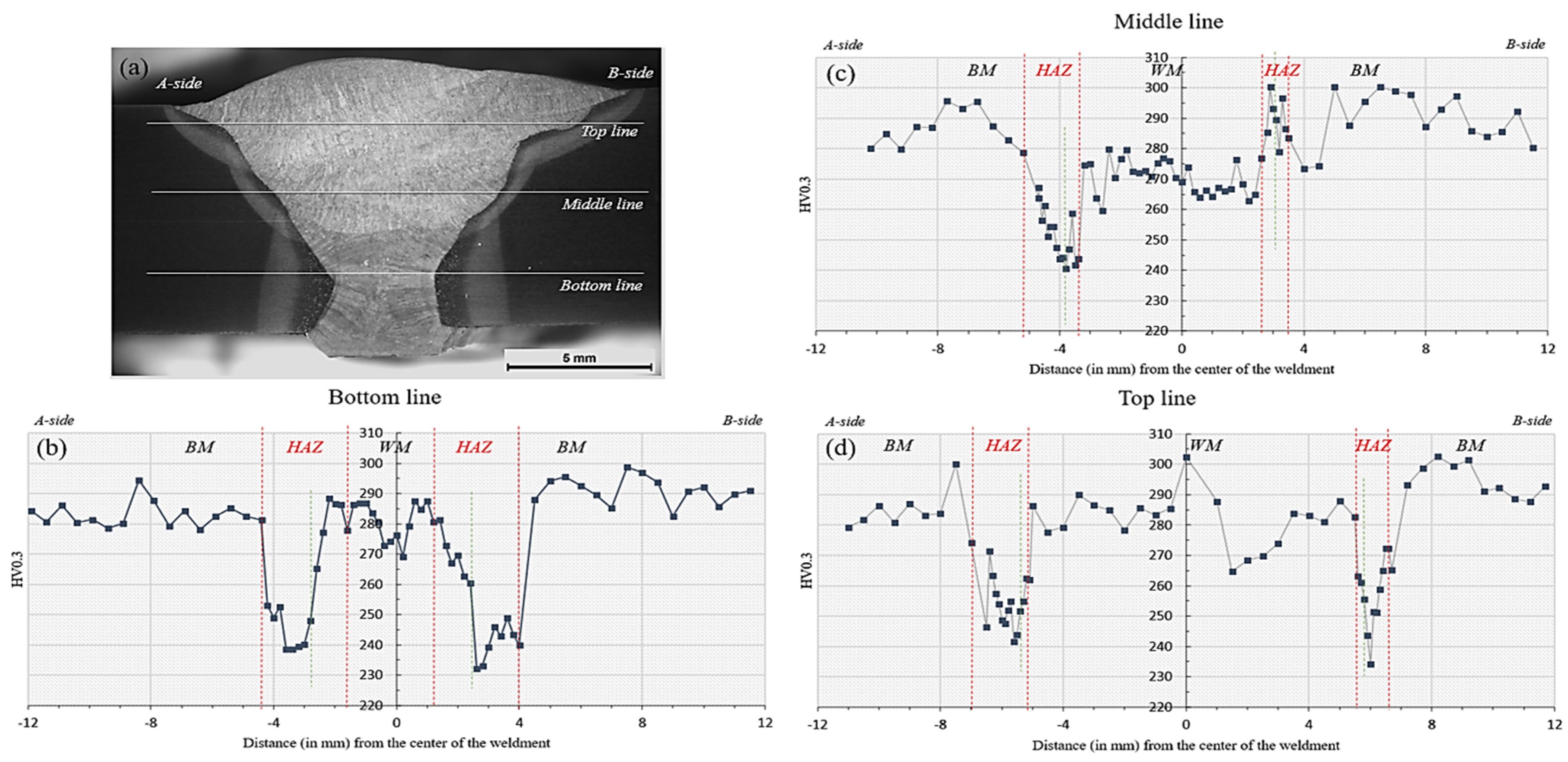
  • Microhardness evaluation confirmed a softening effect within the HAZ. Tensile testing revealed no degradation in the overall mechanical properties of the weldments. Notably, failure consistently occurred within the BM region, rather than the HAZ, in a failure mode often observed for hot-rolled steels, indicating a good weld quality.
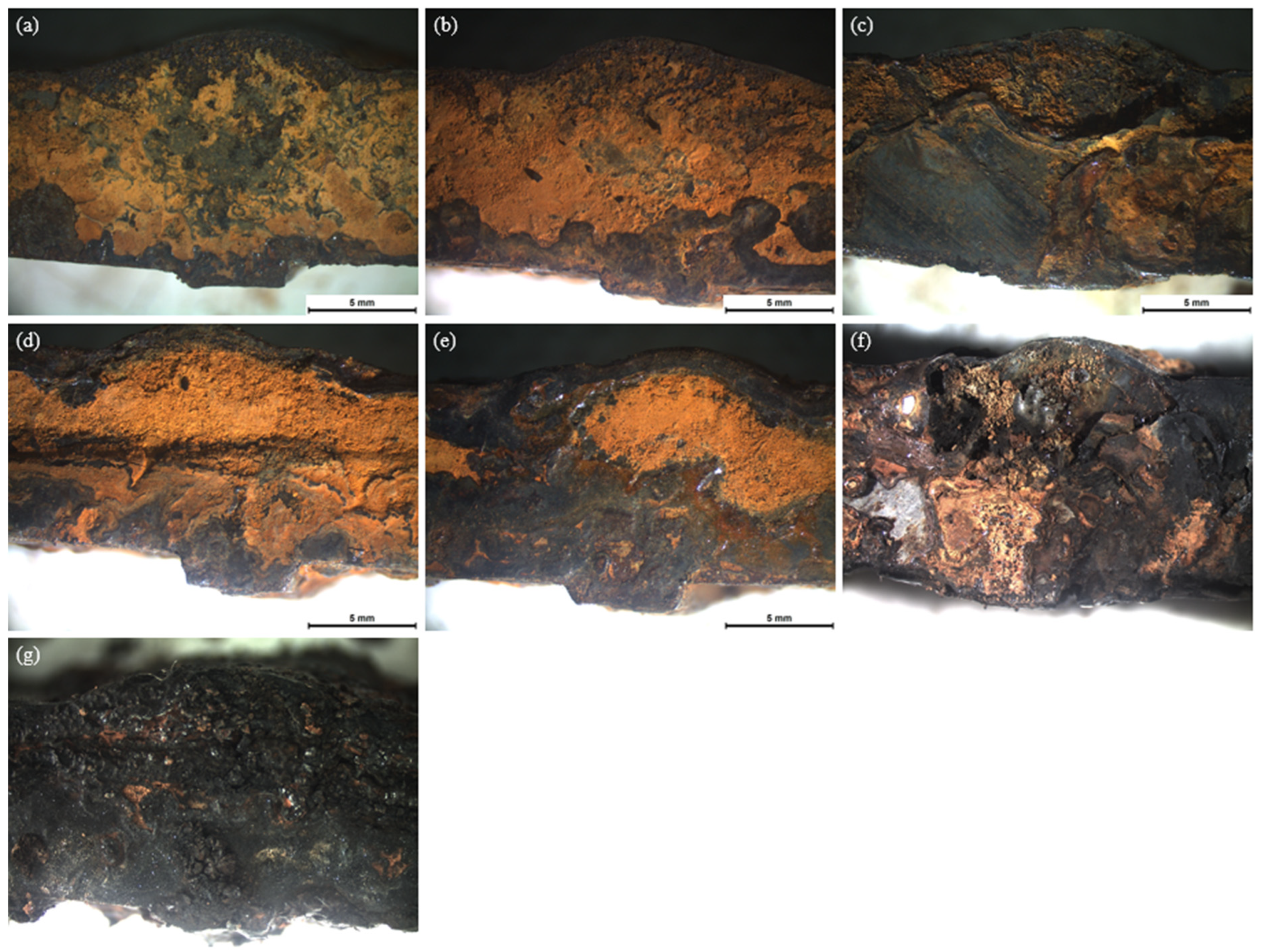
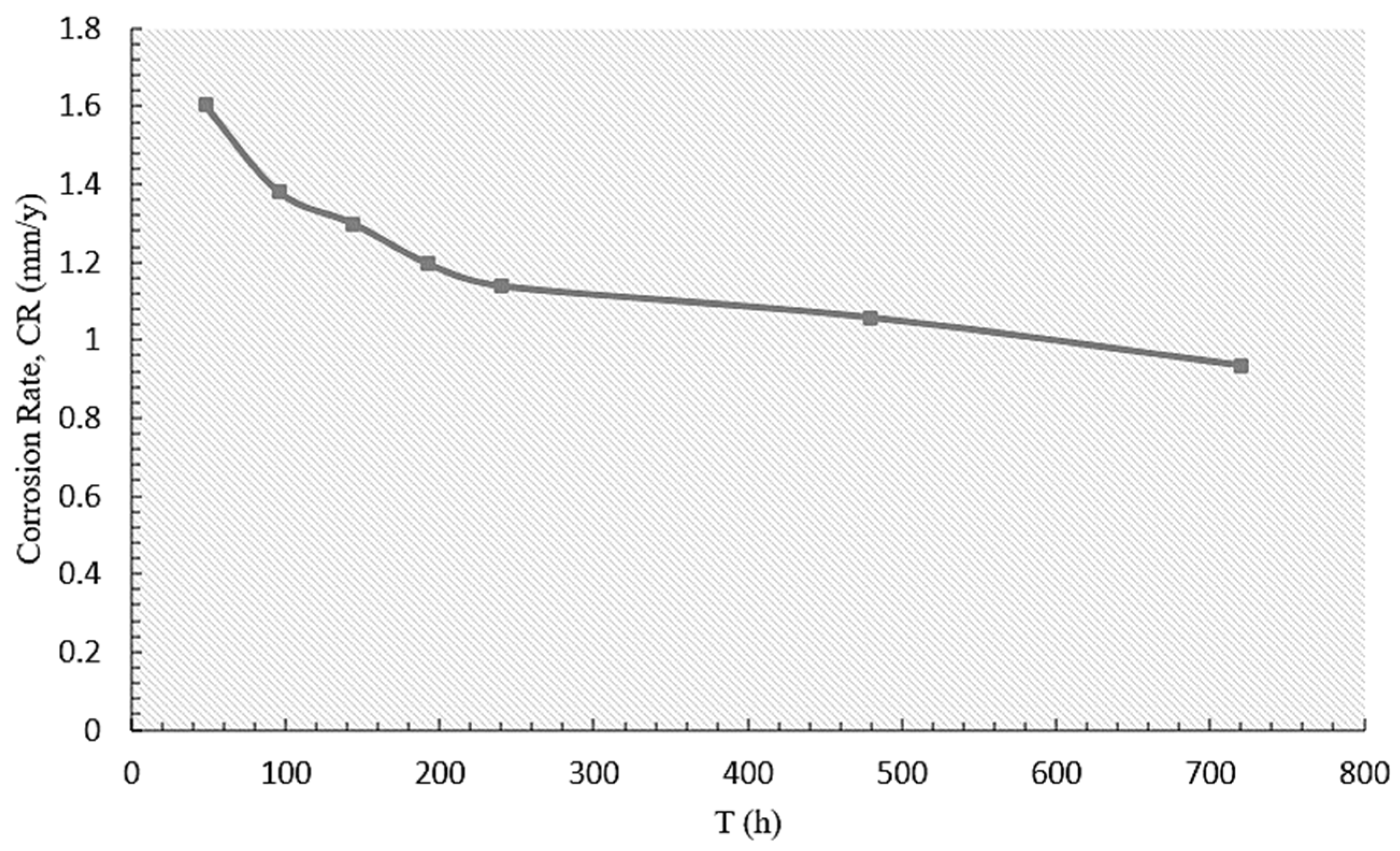
  • Short-term exposure of the welded joints to salt fog resulted in the formation of corrosion pits, primarily on the BM surface. Although prolonged exposure resulted in an increase in both the number and size of the pits on the BM, as well as the presence of microscopic pits on the WM and HAZ surface, the corrosion rate decreased with longer exposure times due to the formation of a protective layer.
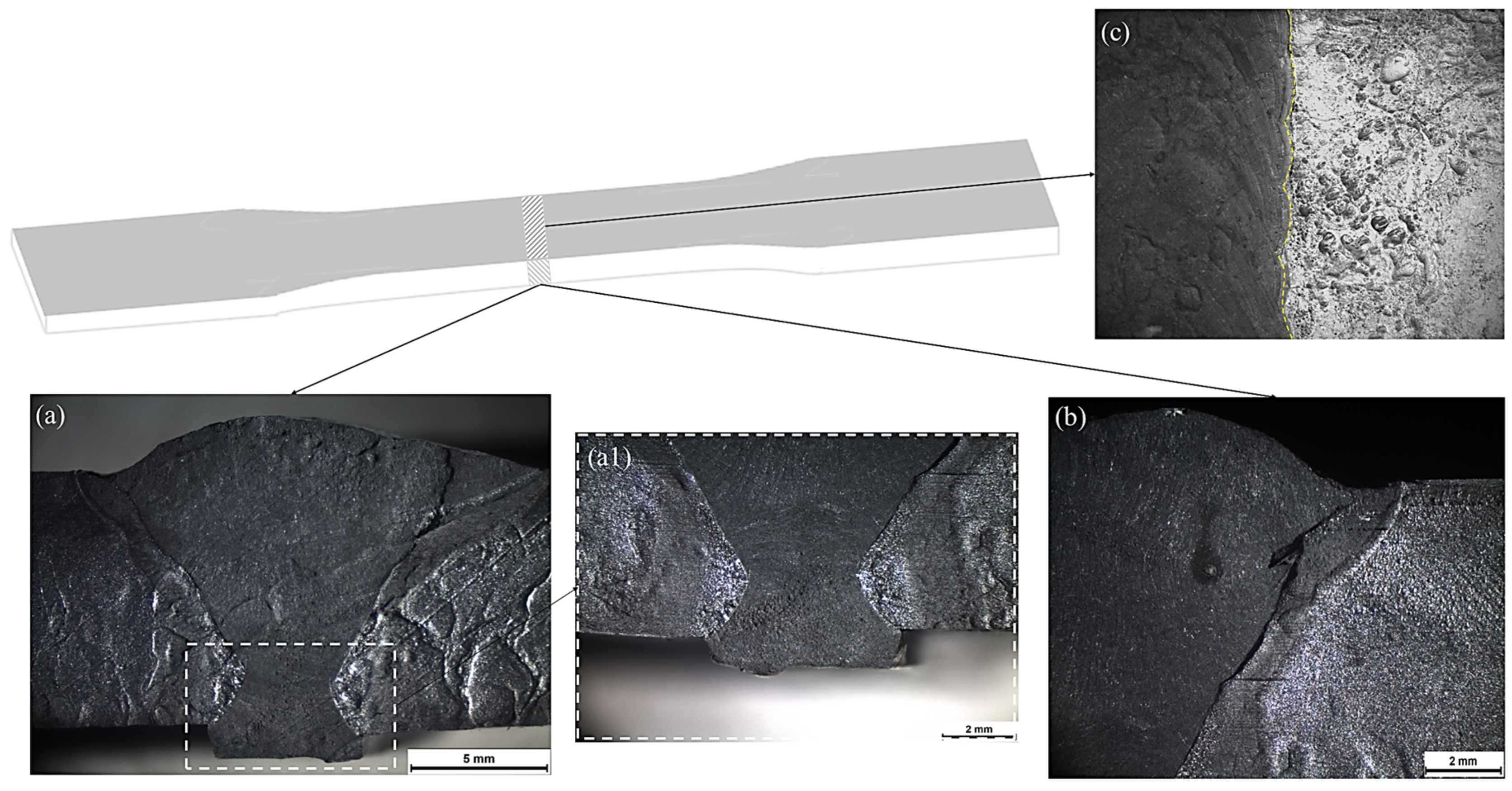
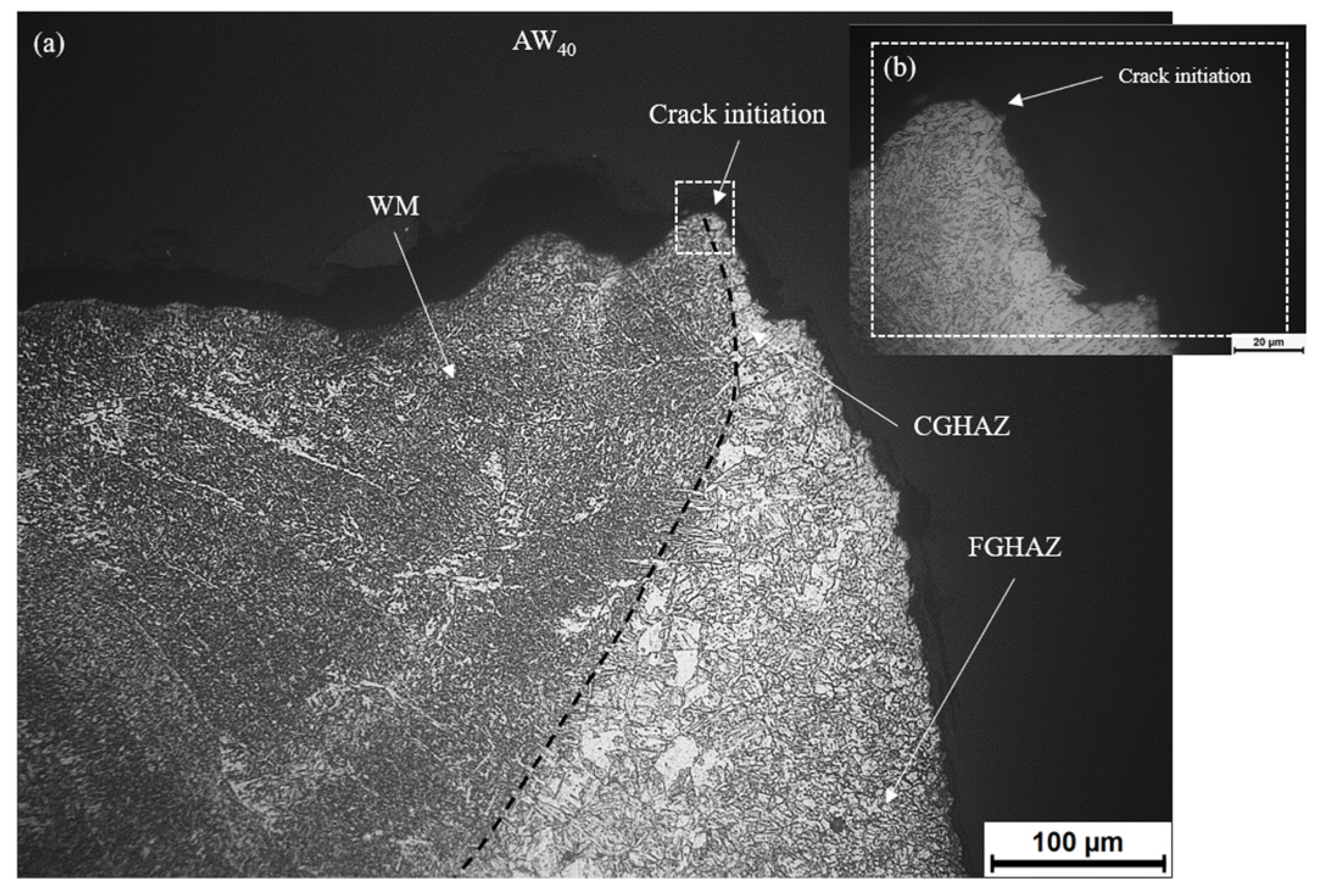
  • Fatigue cracks of the as-welded and pre-corroded specimens were initiated on the face side of the CGHAZ, mainly influenced by the geometry of the weldment and the presence of coarse-grained bainitic matrix. Although pre-corrosion generally reduces the fatigue strength of the welded joints, this is not the case for all specimens, indicating that corrosion may be a less significant factor in determining the specimens’ behavior under cyclic loading for the exposure times employed in this study. Instead, the impact of angular deformation, which induces additional bending stresses during cyclic loading, should also be considered.
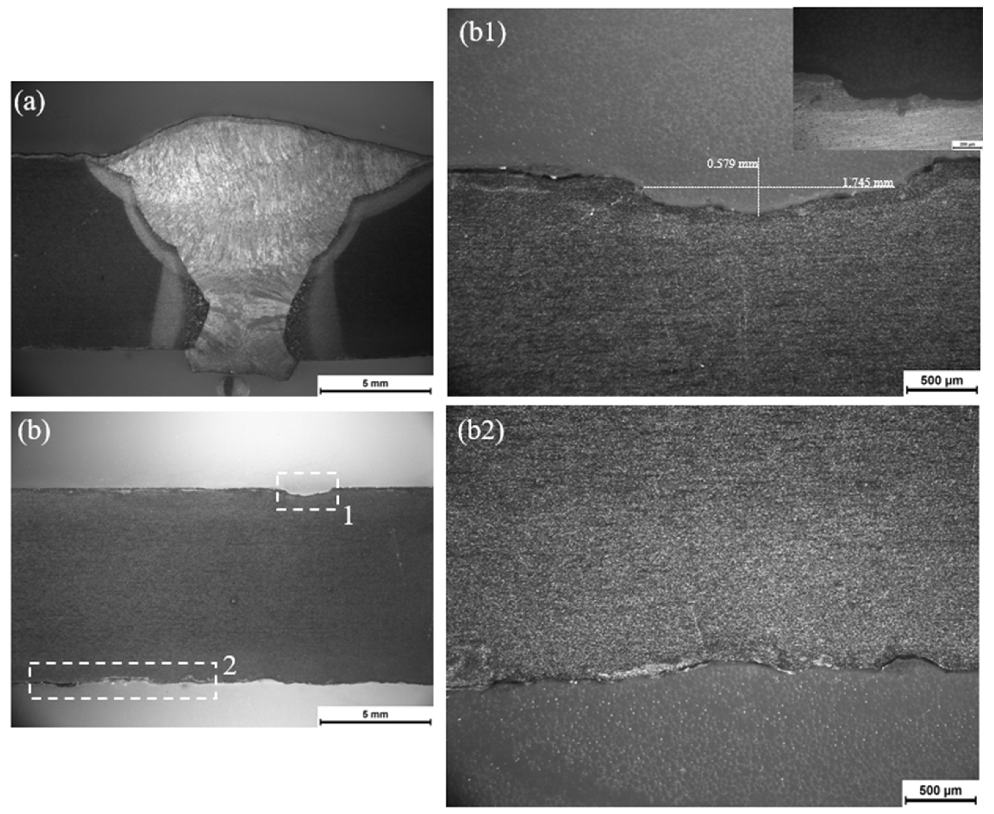
  • Regarding the HFMI treatment, a significant improvement in fatigue life under constant amplitude loading was observed. Plastic deformation caused an increase in microhardness near the surface of the specimens. Beyond a depth of 0.1 mm from the surface, the extent of this increase was reduced.

Author Contributions

S.S. and E.C., methodology, experimental investigation, validation, original draft preparation. A.D.Z., conceptualization, methodology, supervision, validation, review and editing. All authors have read and agreed to the published version of the manuscript.

Funding

This research received no external funding.

Data Availability Statement

The raw and processed data required to reproduce these findings cannot be shared at this time due to technical and time limitations. The data can be shared through direct contact with the corresponding author.

Conflicts of Interest

The authors declare no conflicts of interest.

References

  1. Bhadeshia, H.; Honeycombe, R. Steels: Microstructure and Properties, 4th ed.; Butterworth-Heinmann: Oxford, UK, 2017. [Google Scholar]
  2. Kim, N.J. The Physical Metallurgy of HSLA Linepipe Steels—A Review. J. Met. 1983, 35, 21–27. [Google Scholar] [CrossRef]
  3. Porter, L.; Repas, P. The Evolution of HSLA Steels. J. Met. 1982, 34, 14–21. [Google Scholar] [CrossRef]
  4. Skobir, D.A. High strength low-alloy (HSLA) steels. Mater. Technol. 2011, 45, 295–301. [Google Scholar]
  5. Lahtinen, T.; Vilaça, P.; Infante, V. Fatigue behavior of MAG welds of thermo-mechanically processed 700MC ultra high strength steel. Int. J. Fatigue 2019, 126, 62–71. [Google Scholar] [CrossRef]
  6. Costa, J.D.M.; Ferreira, J.A.M.; Abreu, L.P.M. Fatigue behaviour of butt welded joints in a high strength steel. Procedia Eng. 2010, 2, 697–705. [Google Scholar] [CrossRef]
  7. Guo, W.; Li, L.; Crowther, D.; Dong, S.; Francis, J.A.; Thompson, A. Laser welding of high strength steels (S960 and S700) with medium thickness. J. Laser Appl. 2016, 28, 022425. [Google Scholar] [CrossRef]
  8. Cochrane, R. Phase transformations in microalloyed high strength low alloy (HSLA) steels. In Part II: Phase Transformations in High Strength Steels; Woodhead Publishing: Sawston, UK, 2012; Volume 2, pp. 153–212. [Google Scholar]
  9. Rashid, M. High-Strength, Low-Alloy Steels. Science 1980, 208, 862–869. [Google Scholar] [CrossRef] [PubMed]
  10. Mohrbacher, H. Mohrbacher, H. Mo and Nb Alloying in Plate Steels for High-Performance Applications. In 2011 International Symposium on the Recent Developments in Plate Steels; Association for Iron & Steel Technology: Warrendale, PA, USA, 2011; pp. 169–179. [Google Scholar]
  11. DeArdo, A.J. Multi-phase microstructures and their properties in high strength low carbon steels. ISIJ Int. 1995, 35, 946–954. [Google Scholar] [CrossRef]
  12. Shao, Y.; Liu, C.; Yan, Z.; Li, H.; Liu, Y. Formation mechanism and control methods of acicular ferrite in HSLA steels: A review. J. Mater. Sci. Technol. 2018, 34, 737–744. [Google Scholar] [CrossRef]
  13. Jorge, J.C.F.; de Souza, L.F.G.; Mendes, M.C.; Bott, M.C.; Araújo, L.S.; Santos, V.R.D.; Rebello, J.M.A.; Evans, G.M. Microstructure characterization and its relationship with impact toughness of C–Mn and high strength low alloy steel weld metals—A Review. J. Mater. Res. Technol. 2021, 10, 471–501. [Google Scholar] [CrossRef]
  14. Vimalraj, C.; Kah, P.; Layus, P.; Belinga, E.M.; Parshin, S. High-strength steel S960QC welded with rare earth nanoparticle coated filler wire. Int. J. Adv. Manuf. Technol. 2018, 102, 105–119. [Google Scholar] [CrossRef]
  15. Kou, S. Welding Metallurgy, 2nd ed.; Wiley: Hoboken, NJ, USA, 2003. [Google Scholar]
  16. Tümer, M.; Schneider-Bröskamp, G.; Enzinger, N. Fusion welding of ultra-high strength structural steels—A review. J. Manuf. Process. 2022, 82, 203–229. [Google Scholar] [CrossRef]
  17. Hochhauser, F.; Ernst, W.; Rauch, R.; Vallant, R.; Enzinger, N. Influence of the soft zone on the strength of welded modern HSLA Steels. Weld. World 2012, 56, 77–85. [Google Scholar] [CrossRef]
  18. Amraei, M.; Ahola, A.; Afkhami, S.; Björk, T.; Heidarpour, A.; Zhao, X.-L. Effects of heat input on the mechanical properties of butt-welded high and ultra-high strength steels. Eng. Struct. 2019, 198, 109460. [Google Scholar] [CrossRef]
  19. Moravec, J.; Sobotka, J.; Solfronk, P.; Thakral, R. Heat Input Influence on the Fatigue Life of Welds from Steel S460MC. Metals 2020, 10, 1288. [Google Scholar] [CrossRef]
  20. Steimbreger, C.; Gubeljak, N.; Vuherer, T.; Enzinger, N.; Ernst, W.; Chapetti, M. Effect of welding processes on the fatigue behaviour of ultra-high strength steel butt-welded joints. Eng. Fract. Mech. 2022, 275, 108845. [Google Scholar] [CrossRef]
  21. Pollard, B.; Cover, R.J. Fatigue of Steel Weldments. Weld. Res. Suppl. 1972, 544–554. [Google Scholar]
  22. Pantelis, D.I.; Tsiourva, T.E. Corrosion of weldments. In Trends in Oil and Gas Corrosion Research and Technologies; Woodhead Publishing: Sawston, UK, 2017; pp. 249–270. [Google Scholar]
  23. Guo, Y.-B.; Li, C.; Liu, Y.-C.; Yu, L.-M.; Ma, Z.-Q.; Liu, C.-X.; Li, H.-J. Effect of microstructure variation on the corrosion behavior of high-strength low-alloy steel in 3.5wt% NaCl solution. Int. J. Miner. Metall. Mater. 2015, 22, 604–612. [Google Scholar] [CrossRef]
  24. ASM International. Corrosion of Weldments, Davis, J.R., Ed.; ASM International: Materials Park, OH, USA, 2006. [Google Scholar]
  25. Gkatzogiannis, S.; Weinert, J.; Engelhardt, I.; Khoedel, P.; Ummenhofer, T. Corrosion fatigue behaviour of HFMI-treated butt welds. Int. J. Fatigue 2021, 145, 106079. [Google Scholar] [CrossRef]
  26. Ahn, S.-H.; Jr, F.V.L.; Metzger, M.M. Corrosion fatigue of an HSLA steel. Fatigue Fract. Eng. Mater. Struct. 1992, 12, 625–642. [Google Scholar] [CrossRef]
  27. Knysh, V.; Solovei, S.; Motrunich, S.; Lyudmila, N.; Yildirim, H.C. Influence of the accelarated corrosion exposure on the fatigue behaviour of welded joints treated by high frequency mechanical impact. Int. J. Fatigue 2021, 149, 106272. [Google Scholar] [CrossRef]
  28. Gkatzogiannis, S.; Weinert, J.; Engelhardt, I.; Knoedel, P.; Ummenhofer, T. Correlation of laboratory and real marine corrosion for the investigation of corrosion fatigue behaviour of steel components. Int. J. Fatigue 2019, 126, 90–102. [Google Scholar] [CrossRef]
  29. Marquis, G.B.; Barsoum, Z. A Guideline for Fatigue Stength Improvement of High Strength Steel Welded Structures Using High Frequency Mechanical Impact Treatment. Procedia Eng. 2013, 66, 98–107. [Google Scholar] [CrossRef]
  30. Leitner, M.; Simunek, D.; Shah, S.F.; Stoschka, M. Numerical fatigue assessment of welded and HFMI-treated joints by notch stress/strain and fracture mechanical approaches. Adv. Eng. Softw. 2018, 120, 96–106. [Google Scholar] [CrossRef]
  31. Weich, I.; Ummenhofer, T.; Nitschke-Pagel, T.; Dilger, K.; Eslami, H. Fatigue Behaviour of Welded High-Strength Steels after High Frequency Mechanical Post-Weld Treatments. Weld. World 2009, 53, R322–R332. [Google Scholar] [CrossRef]
  32. Yıldırım, H.C.; Marquis, G.; Sonsino, C.M. Lightweight Potential of Welded High-Strength Steel Joints from S700 under Constant and Variable Amplitude Loading by HighFrequency Mechanical Impact (HFMI) Treatment. Procedia Eng. 2015, 101, 467–475. [Google Scholar] [CrossRef]
  33. Moravec, J.; Sobotka, J.; Novakova, I.; Bukovska, S. Assessment the Partial Welding Influences on Fatigue Life of S700MC Steel Fillet Welds. Metals 2021, 11, 334. [Google Scholar] [CrossRef]
  34. Nový, F.; Petrů, M.; Trško, L.; Jambor, M.; Bokůvka, O.; Lago, J. Fatigue properties of welded strenx 700 MC HSLA Steel after Ultrasonic Impact Treatment Application. Mater. Today Proc. 2020, 32, 174–178. [Google Scholar] [CrossRef]
  35. OK Aristorod 69. Available online: https://esab.com (accessed on 2 December 2023).
  36. DOCOL ® The Automotive Steel, “Docol S700MC,” 2021. Available online: https://www.ssab.com (accessed on 25 November 2023).
  37. EN 1011-1; Welding—Recommendations for Welding of Metallic Materials, Part 1: General Guidance for arc Welding. European Committee for Standardization: Brussels, Belgium, 2009.
  38. Daskalopoulos, N. Optimization of Robot Welding GMAW Procedure of S700MC Steel on a Heat Input Basis; National Technical University of Athens: Athens, Greece, 2022. (In Greek) [Google Scholar]
  39. EN ISO 5817; Welding—Fusion-Welded Joints in Steel, Titanium and Their Alloys (Beam Welding Excluded)—Quality Levels for Imperfections. European Committee for Standardization: Brussels, Belgium, 2007.
  40. EN ISO 6520-1; Welding and Allied Processes—Classification of Geometric Imperfections in Metallic Materials—Part 1: Fusion Welding. European Committee for Standardization: Brussels, Belgium, 2007.
  41. ISO 6507-1; Metallic Materials—Vickers Hardness Test—Part 1: Test Method. International Organization for Standardization: Geneva, Switzerland, 2018.
  42. Kumar, V.; Tiwari, S.K.; Sharma, N. Mechanical and surface characterization of interstitial-free steel corroded under wet-dry salt spray and immersion conditions: A comparative study. Mater. Corros. 2023, 74, 1289–1300. [Google Scholar] [CrossRef]
  43. ASTM B117; Standard Practice for Operating Salt Spray (Fog) Apparatus. ASTM International: West Conshohocken, PA, USA, 2011.
  44. EN ISO 7539-1; Corrosion of Metals and Alloys—Stress Corrosion Testing—Part 1: General Guidance on Testing Procedures. European Committee for Standardization: Brussels, Belgium, 2012.
  45. EN ISO 6892-1; Metallic Materials—Tensile testing—Part 1: Method of Test at Room Temperature. European Committee of Standardization: Brussels, Belgium, 2019.
  46. ASTM E468; Standard Practice for Presentation of Constant Amplitude Fatigue Test Results for Metallic Materials. ASTM International: West Conshohocken, PA, USA, 2018.
  47. ASTM E 8M-04; Standard Test Methods for Tension Testing of Metallic Materials. ASTM International: West Conshohocken, PA, USA, 2004.
  48. ASTM E466-96; Standard Practice for Conducting Force Controlled Constant Amplitude Axial Fatigue Tests of Metallic Materials. ASTM International: West Conshohocken, PA, USA, 1996.
  49. Bukovská, Š.; Moravec, J.; Solfronk, P.; Pekárek, M. Assessment of the Effect of Residual Stresses Arising in the HAZ of Welds on the Fatigue Life of S700MC Steel. Metals 2022, 12, 1890. [Google Scholar] [CrossRef]
  50. Baptista, R.; Santos, T.; Marques, J.; Guedes, M.; Infante, V. Fatigue behavior and microstructural characterization of a high strength. Int. J. Fatigue 2018, 117, 1–8. [Google Scholar] [CrossRef]
  51. Wang, P.; Gomes, F.M.; Warchomicka, F.G.; Ernst, W.; Vallant, R.; Poletti, M.C.; Enzinger, N. The effect of thermomechanical welding on the microstructure and mechanical properties of S700MC steel welds. Weld. World 2024, 68, 1053–1069. [Google Scholar] [CrossRef] [PubMed]
  52. Szymczak, T.; Makowska, K.; Kowalewski, Z.L. Influence of the Welding Process on the Mechanical Characteristics and Fracture of the S700MC High Strength Steel under Various Types of Loading. Materials 2020, 13, 5249. [Google Scholar] [CrossRef] [PubMed]
  53. Ricks, R.A.; Howell, P.R.; Barritte, G.S. The nature of acicular ferrite in HSLA steel weld metals. J. Materals Sci. 1982, 17, 732–740. [Google Scholar] [CrossRef]
  54. Lan, L.; Kong, X.; Qiu, C.; Zhao, D. Influence of microstructural aspects on impact toughness of multi-pass submerged arc welded HSLA steel joints. Mater. Des. 2016, 90, 488–498. [Google Scholar] [CrossRef]
  55. Duprez, L.; Leunis, E.; Güngör, Ö.E.; Claessens, S. Hydrogen embrittlement of high strength, low alloy (HSLA) steels and their welds. In Gaseous Hydrogen Embrittlement of Materials in Energy Technologies; Woodhead Publishing: Sawston, UK, 2016; Volume 2, pp. 562–591. [Google Scholar]
  56. Nový, F.; Medvecká, D.; Trško, L.; Bokůvka, O.; Drímalová, P. Effect of Welding Methods on the Mechanical Properties of Domex 700MC Steel. Mater. Res. Proc. 2023, 34, 1–5. [Google Scholar]
  57. Harati, E.; Svensson, L.-E.; Karlsson, L.; Widmark, M. Effect of High Frequency Mechanical Impact treatment on fatigue strength of welded 1300 MPa yield strength steel. Int. J. Fatigue 2016, 92, 96–106. [Google Scholar] [CrossRef]
  58. Kopas, P.; Sága, M.; Jambor, M.; Nový, F.; Trško, L.; Jakubovičová, L. Comparison of the mechanical properties and microstructural evolution in the HAZ of HSLA DOMEX 700MC welded by gas metal arc welding and electron beam welding. MATEC Web Conf. 2018, 244, 01009. [Google Scholar] [CrossRef]
  59. Mičian, M.; Frátrik, M.; Brůna, M. Softening effect in the heat affected zone of laser welded joints of high strength low alloyed steels. Weld. World 2024, 68, 1497–1514. [Google Scholar] [CrossRef]
  60. Zhou, Y.; Chen, J.; Xu, Y.; Liu, Z. Effects of Cr, Ni and Cu on the Corrosion Behavior of Low Carbon Microallying Steel in a Cl- Containing Environment. J. Mater. Sci. Technol. 2013, 29, 168–174. [Google Scholar] [CrossRef]
  61. Guo, J.; Yang, S.; Shang, C.; Wang, Y.; He, X. Influence of carbon content and microstructure on corrosion behaviour of low alloy steels in a Cl- containing environment. Corros. Sci. 2008, 51, 242–251. [Google Scholar] [CrossRef]
  62. Melchers, R.E. A review of Trends for Corrosion Loss and Pit Depth in Longer-Term Exposures. Corros. Mater. Degrad. 2018, 1, 42–58. [Google Scholar] [CrossRef]
  63. Fontana, M.G. Corrosion Engineering, 3rd ed.; McGraw-Hill: New York, NY, USA, 1987. [Google Scholar]
  64. Hobbacher, A. Recommendations for Fatigue Design of Welded Joints and Components, 2nd ed.; IIW Collection; Springer International Publishing: Cham, Switzerland, 2016. [Google Scholar]
  65. Ummenhofer, T.; Gkatzogiannis, S.; Weidner, P. Einfluss der Korrosion auf die Ermüdungsfestigkeit von Konstruktionen des Stahlwasserbaus. In Proceedings of the Kolloquium Korrosionsschutz und Tragfähigkeit bestehender Stahlwasserbauverschlüsse, Karlsruhe, Germany, 8–9 February 2017. [Google Scholar]
  66. Alipooramirabad, H.; Ghomashchi, R.; Paradowska, A.; Reid, M. Residual stress-microstructure-mechanical property interrelationships in multipass HSLA steel welds. J. Mater. Process. Technol. 2016, 231, 456–467. [Google Scholar] [CrossRef]
  67. Lago, J.; Trško, L.; Jambor, M.; Nový, F.; Bokůvka, O.; Mičian, M.; Pastorek, F. Fatigue life improvement of the high strength steel welded joints by ultrasonic impact peening. Metals 2019, 9, 619. [Google Scholar] [CrossRef]
  68. Bakkar, M.A.; Kanrar, B.; Das, D. Low Cycle Fatigue Behavior of a Microalloyed Steel. In Processing and Characterization of Materials; Springer: Singapore, 2021. [Google Scholar]
  69. Tomar, B. Fatigue Analyses of GMAW Welds of Thermo-Mechanically Processed 700MC Ultra High Strentgh Steel. Int. J. Res. Eng. Sci. Manag. 2020, 3, 220–225. [Google Scholar]
Figure 1. (a) Schematic representation of joint design and welding sequence (dimensions in mm); (b) weld macrostructure.
Crystals 14 00609 g001
Figure 2. Standard HFMI device.
Crystals 14 00609 g002
Figure 3. (a) Weldment macrostructure and (b) columnar structure of the weldment. Heat flow after the 1st pass is indicated by the arrows. A: WM, B: CGHAZ, C: FGHAZ, D: BM.
Crystals 14 00609 g003
Figure 4. Microstructure of the S700MC BM. (a) LOM and (b) SEM.
Crystals 14 00609 g004
Figure 5. Microstructure of the WM, consisting of different ferrite variants.
Crystals 14 00609 g005
Figure 6. WM microstructure of the (a,c) 1st and (b,d) 2nd pass.
Crystals 14 00609 g006
Figure 7. Microstructure within the CGHAZ of the welded S700MC. (a) Fine lath carbide/bainite within prior austenite grain boundaries (PAGBs) and (b) plates of acicular ferrite within austenite grains.
Crystals 14 00609 g007
Figure 8. Microstructure within the FGHAZ of the welded S700MC. (a) Fine-grained ferrite and (b) presence of bainite at ferritic grain boundaries. The circle indicates probable bainite presence.
Crystals 14 00609 g008
Figure 9. (a) Macrostructure of the weldment and microhardness variation along (b) the bottom, (c) the middle and (d) the top line of the weldment.
Crystals 14 00609 g009
Figure 10. Stress–strain curve of S700MC in the as-welded condition.
Crystals 14 00609 g010
Figure 11. (a) Uniaxial tensile test of as-welded S700MC steel and (b,c) delamination failure mode of the BM.
Crystals 14 00609 g011
Figure 12. Side surface of the pre-corroded specimens after exposure to the salt spray for various durations: (a) 48 h, (b) 96 h, (c) 144 h, (d) 192 h, (e) 240 h, (f) 480 h and (g) 720 h.
Crystals 14 00609 g012
Figure 13. Macroscopic examination of the pre-corroded (720 h) S700MC weldment after the removal of corrosion products: (a,a1,b) side and (c) upper surface (yellow line indicates the boundary between WM and HAZ).
Crystals 14 00609 g013
Figure 14. Cross-section of the pre-corroded S700MC weldment after 720 h of exposure to salt fog spray. (a) WM, (b) BM, (b1,b2) broad pits observed on the BM cross-section near the surface.
Crystals 14 00609 g014
Figure 15. Corrosion rate curve as a function of exposure time.
Crystals 14 00609 g015
Figure 16. S-N curves for the as-welded, pre-corroded and HFMI-treated S700MC specimens.
Crystals 14 00609 g016
Figure 17. (a,b) Cross-section of the fatigue crack initiation site.
Crystals 14 00609 g017
Figure 18. Macroscopic images of fractured surfaces of (a) AW30, (b) AW40, (c) C30 and (d) C40.
Crystals 14 00609 g018
Figure 19. (a) Macrostructure of the fracture surface. Microstructure of specimen AW30 observed through SEM, for selected areas of the (b) crack initiation site, (c) propagation zone, (d) final fracture zone.
Crystals 14 00609 g019
Table 1. Chemical compositions of S700MC steel and Ok Aristorod 69 (filler metal) [35,36].
wt. %CSiMnPSAlNb *V *Ti *NiCr Mo
S700MCmax 0.12max 0.21max 2.1max 0.02max 0.01min 0.015max 0.09max 0.2max 0.15---
Filler Metal0.0890.531.54------1.230.260.24
* sum of Nb, V and Ti = max 0.22% (Fe bal.).
Table 2. Parameters of welding process.
No. of PassCurrent (A)Voltage (V)Type of CurrentTravel Speed (cm/min)Heat Input (kJ/mm)
1–418030DC350.7405
Table 3. Parameters of HFMI process.
Travel SpeedDistanceSpeedIntensityAir PressureDepth of the Treatment
Toe: 64.5 s
Root: 63.5 s
35 cm5.5 mm/s2 Revolutions7 Bars0.20–0.25 mm
Table 4. Fatigue test results for the as-welded, pre-corroded and HFMI-treated specimens.
AW85AW40AW30aAW30bAW25AW20
Δσ (MPa)
Nf (Cycles)
535.5252189189157.5126
8842156,997705,017402,051773,9581,559,422
C85C50C40C30aC30b
535.5315252189189
16,87182,508150,0544,307,762263,365
HFMI 40HFMI30aHFMI30bHFMI25C20
252189189157.5126
263,741548,013589,6111,162,1143,292,732
Disclaimer/Publisher’s Note: The statements, opinions and data contained in all publications are solely those of the individual author(s) and contributor(s) and not of MDPI and/or the editor(s). MDPI and/or the editor(s) disclaim responsibility for any injury to people or property resulting from any ideas, methods, instructions or products referred to in the content.

