Article

Effect of Semi-Conductive Layer Modified by Magnetic Particle SrFe12O19 on Charge Injection Characteristics of HVDC Cable

Institute of Advanced Electrical Materials, Qingdao University of Science and Technology, Qingdao 266042, China
*
Author to whom correspondence should be addressed.
Polymers 2019, 11(8), 1309; https://doi.org/10.3390/polym11081309
Submission received: 22 June 2019 / Revised: 16 July 2019 / Accepted: 1 August 2019 / Published: 5 August 2019

Abstract

:
For high voltage direct current (HVDC) cable, a semi-conductive layer lies between the conductor and the insulation layer; as the charge migrates the path from the conductor to the insulation material, it will affect space charge injection. In this work, the research idea of changing the injection path of moving charges within semi-conductive layer by magnetic particles was proposed. Semi-conductive composites with different SrFe12O19 contents of 1 wt.%, 5 wt.%, 10 wt.%, 20 wt.%, and 30 wt.% were prepared, and the amount of injected charges in the insulation sample was characterized by space charge distribution, polarization current, and thermally-stimulated depolarization current. The experimental results show that a small amount of SrFe12O19 can significantly reduce charge injection in the insulation sample, owing to the deflection of the charge migration path, and only part of the electrons can enter the insulation sample. When the content is 5 wt.%, the insulation sample has the smallest charge amount, 0.89 × 10⁻⁷ C, decreasing by 37%, and the steady-state current is 6.01 × 10⁻¹⁰ A, decreasing by 22%. When SrFe12O19 content exceeds 10 wt.%, the charge suppression effect is not obvious and even leads to the increase of charge amount in the insulation sample, owing to the secondary injection of charges. Most moving charges will deflect towards the horizontal direction and cannot direct access to the insulation sample, resulting in a large number of charges accumulation in the semi-conductive layer. These charges will seriously enhance the interface electric field near the insulation sample, leading to the secondary injection of charges, which are easier to inject into the insulation sample.

1. Introduction

Space charge accumulation and suppression methods of high voltage direct current (HVDC) cable have been hot research topics with the development and application of higher voltage grade cable [1]. Space charge accumulation in an insulation layer will cause local electric field distortion, accelerating the degradation and aging of the insulation material [2,3,4,5]. A semi-conductive shielding layer as an essential component of HVDC cable plays an important role in uniform electric field and makes the conductor wire core and the insulation layer connect tightly [6,7,8,9,10,11,12]. Besides, it is also a direct path of charge injected from the conductor to the insulation layer, which has a great impact on charge injection and accumulation in the insulation layer [10,11,13].
As for the space charge problem of HVDC cables, there have many works focusing on the insulation materials low-density polyethylene (LDPE) and cross-linked polyethylene (XLPE) in past two decades, which mainly include the charge transport characteristics and the modification of insulating materials [14,15,16,17,18,19,20,21,22,23]. The most representative working was the study of nanocomposites, where the space charge can be effectively suppressed when a small amount of inorganic nano-particles are doped into the polymer matrix, while nanocomposite materials are still far from the application of higher voltage grade cable due to the limitation of the purity of insulation material.
In recent years, there also have some studies that pay attention to the semi-conductive layer of HVDC cable. A semi-conductive layer is a kind of composite, which is mainly composed of carbon black (CB), ethylene-vinyl acetate copolymer (EVA), polyethylene (PE). At present, the related researches mainly focused on the modification of the semi-conductive material by adjusting the filler ratio, type, or adding the second filler [24,25,26,27,28,29,30,31]. The objective was to improve surface finish or inhibit a positive temperature coefficient (PTC) effect, while the charge suppression effect was not obvious. If one can control the path of moving charges in the semi-conductive layer, the charges injected from the metal to the insulation layer can be effectively suppressed.
SrFe12O19, as an important magnetic particle, has been widely used in information recording, electronic communication and electronic equipment [32]. Some composite materials based on a polymer matrix, such as SrFe12O19/PA6, SrFe12O19/PP, and SrFe12O19/PVC, have been reported in study of the magnetic properties of composite materials [33,34,35,36,37]. However, the effect of Lorentz force generated by magnetic particles on moving charges in composites has never been studied. According to the electromagnetic field theory, the moving charges in the magnetic field are affected by Lorentz force, and their moving path will be changed. Therefore, the research idea of changing the injection path of moving charges within semi-conductive layer by magnetic particles was proposed, as shown in Figure 1.
In this paper, semi-conductive composites with different SrFe12O19 contents of 1 wt.%, 5 wt.%, 10 wt.%, 20 wt.%, and 30 wt.% were prepared. SrFe12O19/semi-conductive composites characterizations, including infrared spectrum analysis, the SEM and element analysis, hysteresis loops, and resistivity, are introduced in Section 2. A simplified cable structure ‘Metal electrode—Semi-conductive composite—Insulation sample—Metal electrode’ (M-S-I-M) was used to measure space charge distribution, polarization current, and thermally-stimulated depolarization current in the insulation sample, as shown in Section 3. The charge injection characteristics in the insulation sample under the action of semi-conductive layer with different SrFe12O19 contents was compared, and the mechanism was analyzed, which is shown in Section 4.

2. Sample Preparation and Characterization

2.1. Sample Preparation

The semi-conductive matrix (Borealis, Europe) used in the experiment is a semi-conductive composite for HVDC cable, which is composed of CB, EVA, PE. SrFe12O19 with a size of 800 nm produced by Aladdin Industrial Corporation (Shanghai, China) was used. In order to avoid agglomeration, improve the dispersion of SrFe12O19 particles in the semi-conductive matrix and lower the interface between the two-phase materials, surface modifications of SrFe12O19 particles were firstly implemented using silane coupling agent KH550 before mixing. The interaction between the surface of SrFe12O19 particles and the coupling agent was analyzed by infrared spectroscopy, as shown in Figure 2.
As can be seen from Figure 2, an absorption peak appears near 2392 cm−1, which is the characteristic absorption peak in stretch vibration of CH2 in the coupling agent. The C-N peak appears at 1333 cm−1, and the characteristic peak of the Si-O-Si long chain appears at 1082 cm−1. In addition, there are many peaks below 1000 cm−1, which are out-of-plane bending vibration peaks of C-H. The results show that the surface of SrFe12O19 particles were successfully modified by the KH550.
SrFe12O19/semi-conductive composites were prepared by the melt blending method. Prior to the preparation, the modified SrFe12O19 and semi-conductive composite were dried in a vacuum chamber. Firstly, the semi-conductive matrix was blended in the internal mixer at 135 °C for 5 min, and the desired amount of SrFe12O19 was added to the internal mixer and blended for 15 min. Five kinds of composites with different SrFe12O19 contents were obtained. Secondly, the films of SrFe12O19/semi-conductive composites were prepared by the vulcanizing press. After that, the samples was cooled for 10 min at 10 MPa. Finally, SrFe12O19/semi-conductive composites with five different contents of 1 wt.%, 5 wt.%, 10 wt.%, 20 wt.%, and 30 wt.% were obtained. Adopting the same method, the insulation sample, XLPE, with a thickness of 300 μm was prepared.

2.2. Characterization of SrFe12O19/Semi-Conductive Composites

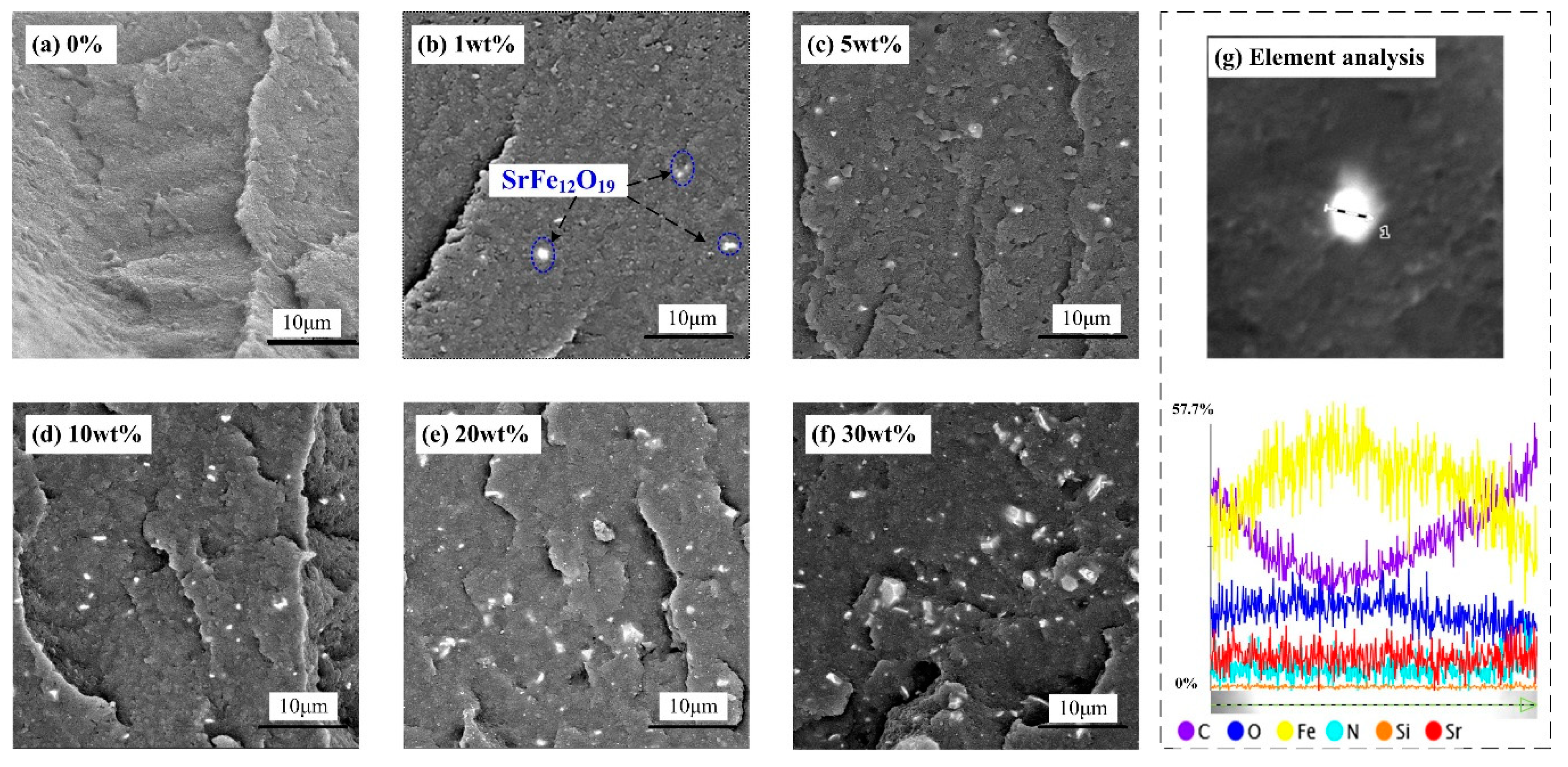
2.2.1. Micromorphology

The cross-section micromorphology of composites were observed. Figure 3 shows the SEM images and element analysis of SrFe12O19/semi-conductive composites.
Figure 3a–f show SEM images of cross sections of SrFe12O19/semi-conductive composites with the contents of 0%, 1 wt.%, 5 wt.%, 10 wt.%, 20 wt.%, and 30 wt.%, respectively. It can be observed that the SrFe12O19 particles are well-dispersed in the semi-conductive matrix, as shown in the blue region marker in Figure 3b. The highlighted particles in Figure 3a–f are analyzed by energy spectrum analysis. As shown in Figure 3g, the content of Fe element across the test line is the highest, about 57.7%, followed by the C and O element, and the content of C is the highest at both ends of the test line. The test results are consistent with the SEM observation of the test area in Figure 3g. It can be confirmed that SrFe12O19 particles were well blended with the semi-conductive matrix.

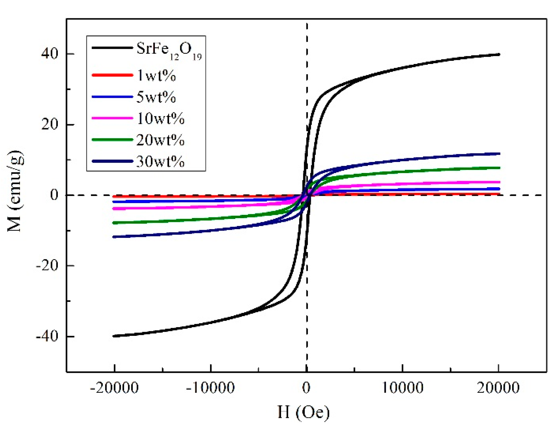
2.2.2. Hysteresis Loop of SrFe12O19/Semi-Conductive Composites

The hysteresis loops of SrFe12O19 particles and SrFe12O19/semi-conductive composites with different doping contents at room temperature were measured, as shown in Figure 4.
The measured results show that the residual magnetization of pure SrFe12O19 particles is 12.24 emu/g. The residual magnetization of SrFe12O19/semi-conductive composites are 0.078 emu/g (1 wt.%), 0.36 emu/g (5 wt.%), 0.73 emu/g (10 wt.%), 1.52 emu/g (20 wt.%), and 2.31 emu/g (30 wt.%).
Compared with pure SrFe12O19 particles, the residual magnetization intensity of SrFe12O19/semi-conductive composite decreases. At the same time, it can be found that the more doped SrFe12O19 particles are, the greater the residual magnetization intensity. Because magnetic particles are surrounded by the semi-conductive matrix, its surface energy is reduced, resulting in difficulty of the magnetization orientation process. Besides, the CB particles in semi-conductive matrix have some diamagnetism. Finally, the doping concentration of SrFe12O19 particles is proportional to the magnetization intensity.

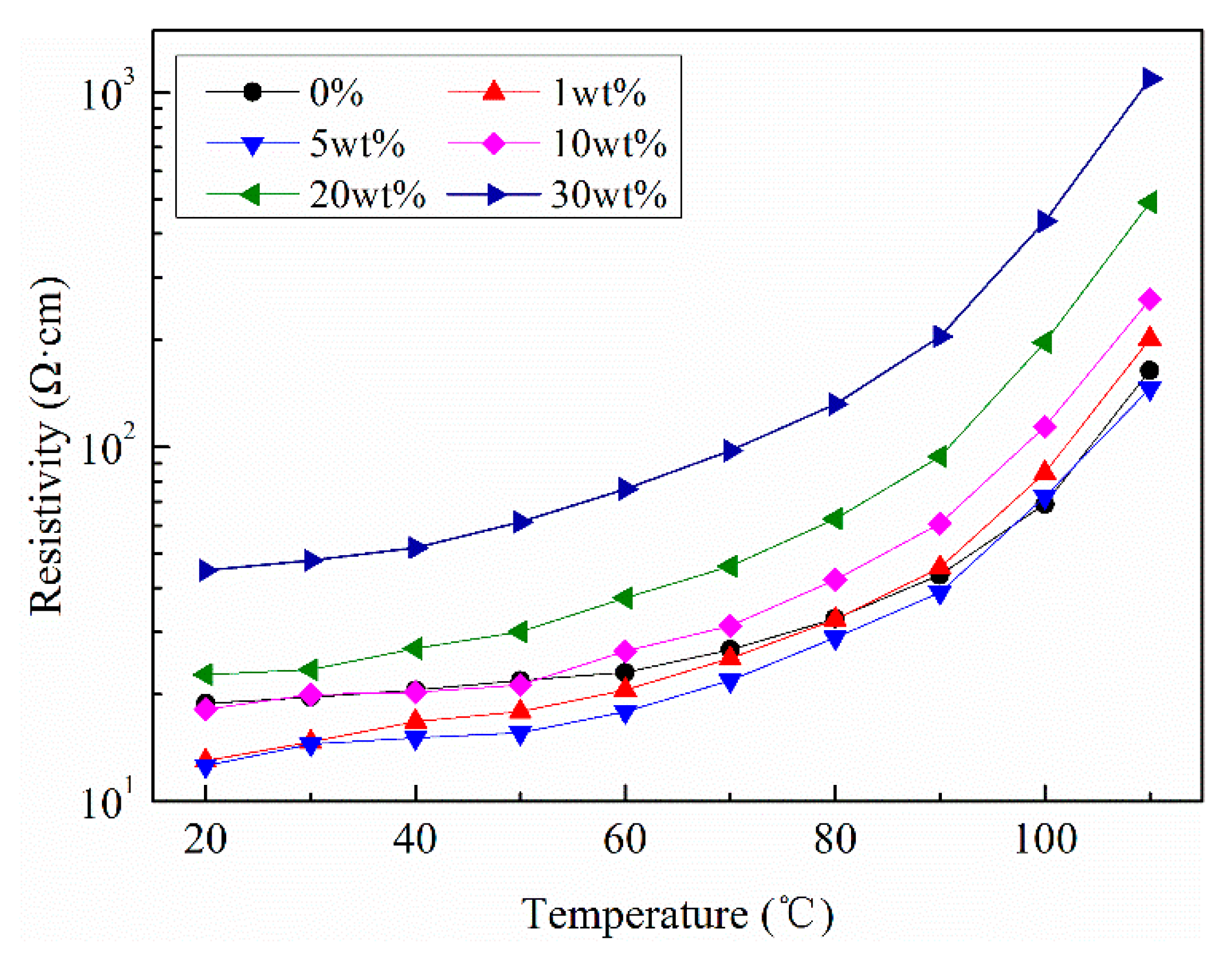
2.2.3. Resistivity of SrFe12O19/Semi-Conductive Composites

Resistivity of SrFe12O19/semi-conductive composites were measured at different temperatures by semi-conductvie resistance test device, as shown in Figure 5.
It can be seen that the resistivity of composites with contents of 0%, 1 wt.%, and 5 wt.% do not change obviously, showing a slightly decrease in partial enlarged drawing, while when SrFe12O19 particles exceeds 10 wt.%, the resistivity increases significantly. That is mainly due to the fact that the resistivity of SrFe12O19 particles is much higher than that of CB particles. In semi-conductive composite without SrFe12O19 particles, its resistivity mainly depends on CB particles. When SrFe12O19 particles are doped, the original conductive channel will be blocked and the resistivity will increase. Therefore, the higher the doping contents of SrFe12O19 particles, the greater the resistivity of composites. In addition, it can be found that the PTC effect becomes evident when the temperature exceeds 90 °C, while for low doping concentration of 1 wt.% and 5 wt.%, the change of resistivity slowly rises with the increasing temperature. This indicates that a small amount of magnetic particles doping cannot affect the PTC effect of the semi-conductive matrix.

3. Experimental Results and Analysis

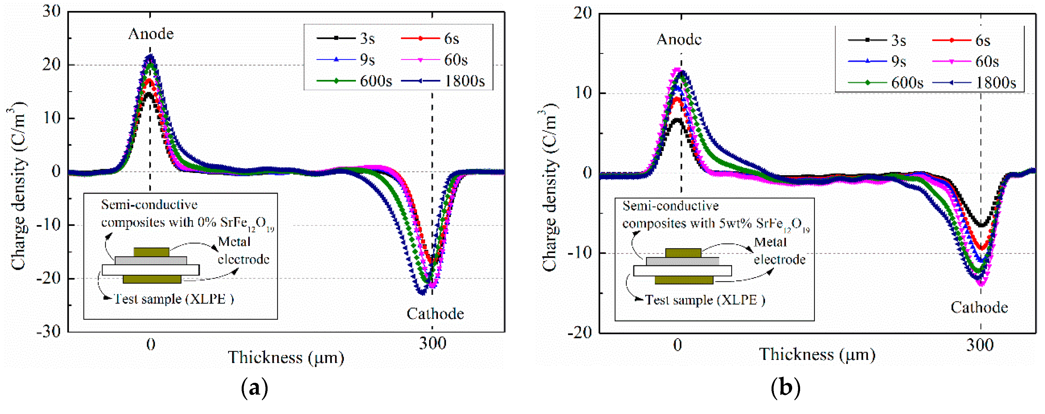
3.1. Space Charge Characteristics

Space charges in insulation material stressed by DC voltage mainly comes from two parts: homo-charges generated by the injection of electrode and the hetero-charges generated by the ionization of impurity particles [38]. For PE, when the electric field exceeds about 10 kV/mm, the injected charges from the electrodes are dominated, which are the main source of the accumulated charges in the insulation material.
The pulse electro-acoustic (PEA) method can be used to intuitively observe space charge distribution in the insulation material. For the method, the semi-conductive layer between the metal electrode and the insulation material plays the role of acoustic impedance matching, meanwhile it will affect the charge injection in the insulation material. In the experiments, semi-conductive composite materials with different SrFe12O19 contents were used as the semi-conductive layer in the PEA test, and XLPE films with the same conditions were used as the test samples. The applied electric field was 20 kV/mm, keeping time for 1800 s. The influence of SrFe12O19/semi-conductive composites on the space charge distribution of the same insulation layer were observed. Figure 6 shows space charge distribution in XLPE under semi-conductive composites with SrFe12O19 contents of 0% and 5 wt.%. Figure 7 shows space charge distributions at 1800 s in XLPE under semi-conductive composites with different SrFe12O19 concentrations.
As can be seen from Figure 6, the charges near interface between the electrode and the insulation sample are reduced under the action of the semi-conductive layer doped with a small amount of SrFe12O19. Generally, these charges near the electrode are mainly composed of the induced charge and the injected charge. Keeping the same applied electric field, the induced charges near the electrode will remain unchanged. Hence, the difference of the charges near the electrode mainly come from the injected charge from the electrode. Comparing Figure 6a,b, for the semi-conductive composites without SrFe12O19, the maximum charges near the two electrodes are 21.75 C/m3 and 22.77 C/m3, respectively. After doping by SrFe12O19 with 5 wt.%, the interface charges decrease to 13.11 C/m3 and 14.03 C/m3, respectively. This is because when the charges injected from the metal electrode to the insulating sample pass through the SrFe12O19/semi-conductive composites, the moving charges will be affected by the horizontal Lorentz force, leading to the deflection of the charge migration path. In addition, the moving charges are subjected to the electric field force in the vertical direction, and only some of the electrons enter the insulation sample.
Space charge distributions in the insulation sample at 1800 s were compared under the action of semi-conductive layer with different SrFe12O19 contents, as shown in Figure 7. It can be seen that the accumulated charges in the insulation samples firstly decreases and then increases with the increase of SrFe12O19 content. When the content is 5 wt.%, the insulation sample has the minimum charges, 0.89 × 10⁻⁷ C, reduced by about 37% than that without doping. When SrFe12O19 content is high, the charge amount in the insulation sample increases. It reaches 1.75 × 10⁻⁷ C at 30 wt.%, increased by about 24% than that without doping.
When SrFe12O19 content is high, a large Lorentz force will be generated in the SrFe12O19/semi-conductive composites, most moving charges will deflect towards the horizontal direction, and cannot direct access to the insulation sample, resulting in a large number of charges accumulation in the semi-conductive layer. These accumulated charges will cause local electric field distortion, which will enhance the interface electric field between the semi-conductive layer and the insulation sample, leading to the secondary injection of charges, which are easier to inject into the insulation sample.

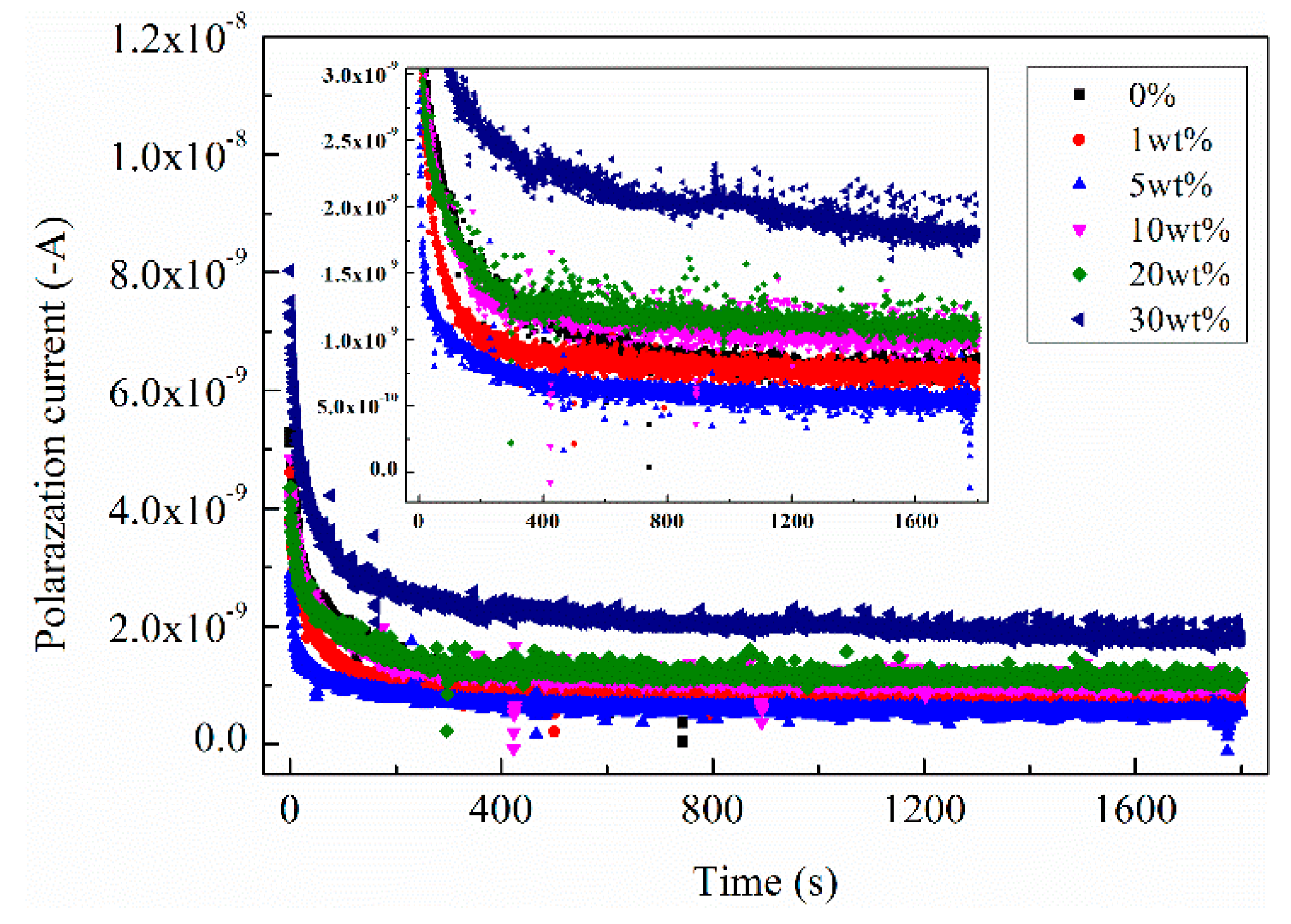
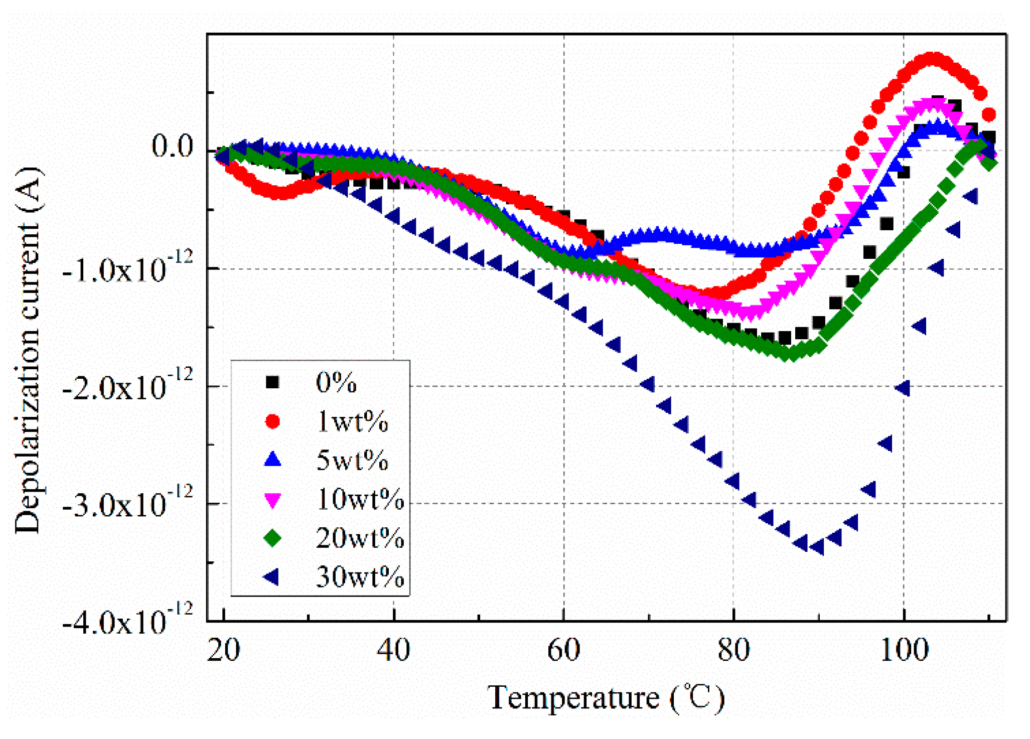
3.2. Polarization and Depolarization Current Characteristics

The polarization current can reflect the charge transport characteristics of the insulation sample during applying voltage [5,39]. The depolarization current can reflect the trapped charges in the insulation sample, which mainly come from the charge’s injection under the strong electric filed [5,39]. In the experiment, the semi-conductive layer modified with different SrFe12O19 was placed between the metal electrode and the insulating sample, forming the structure of ‘M-S-I-M’. The polarization current passing through the insulation sample under the action of the modified semi-conductive layer was measured by electrometer. After removing the voltage, the thermal stimulation depolarization current was measured by the Novocontrol system. Figure 8 shows polarization current of XLPE under semi-conductive composites with different SrFe12O19 concentrations.
It can be seen from Figure 8, when SrFe12O19 content is low, the current in the insulation sample decreases to some extent. It is 6.01 × 10⁻¹⁰ A for the content of 5 wt.%, which is about 22% lower than that without doping. When SrFe12O19 content exceeds 10 wt.%, the current gradually increases with the increase of the magnetic particle content. Especially when the content is high, the current increases significantly, reaching 1.80 × 10⁻⁹ A for 30 wt.%.
In order to further verify the influence of SrFe12O19 content on the charge injection of insulation sample, after removing the voltage, the thermal stimulation depolarization current of the insulation sample was measured. In the test, the heating rate was set to 1 °C/min, and the heating range changes from 20 °C to 100 °C. The test results are shown in Figure 9.
It can be seen that the depolarization current in the insulation sample is significantly different for different SrFe12O19 content. When SrFe12O19 content is low, the depolarization current is less than that without doping. The maximum current is 8.52 × 10⁻¹³ A for 5 wt.%. When SrFe12O19 content exceeds 20 wt.%, the current significantly increases, it reaches 3.4 × 10⁻¹² A for 30 wt.%, which is consistent with the trend of polarization current.

4. Discussion

The experimental results (space charge distribution, polarization current, and depolarization current) indicate that the semi-conductive composites containing a small amount of SrFe12O19 will inhibit the charge injection from the metal electrode into the insulation sample to some extent. Because the moving charges in the semi-conductive layer are affected by electric field and magnetic field, the result is the deflection of the charge motion path. Figure 10 shows a schematic diagram of charge movement path in the SrFe12O19/semi-conductive composites under the combined action of electric field and magnetic field.
Under the strong electric field, the free charges in the metal electrode will hop through the interface barrier and migrate towards the insulation sample. The moving charges are affected by the electric field force F1, and most of them will be injected into the insulation sample along the direction of electric field, and their movement trajectory is approximately straight, as shown in Figure 10a.
When a small amount of SrFe12O19 is doped into the semi-conductive layer, the experimental results show that the charges in the insulation sample are suppressed to some extent. When the content is 5 wt.%, the insulator sample has the smallest charge amount, 0.89 × 10⁻⁷ C, decreasing by about 37%, and the steady-state current is 6.01 × 10⁻¹⁰ A, decreasing by about 22%. Because the moving charges are deflected by Lorentz force when they pass through the semi-conductive composites. The schematic diagram of electron movement is shown in Figure 10b. When movement charges pass through the semi-conductive layer doped with the SrFe12O19, they are affected by both the electric field force F1 and the magnetic field force F2. Assume that the electrons in the metal are incident perpendicular to the insulation sample, and the initial rate is V0. When the movement electrons pass through the SrFe12O19/semi-conductive composites, they are subjected to the horizontal Lorentz force F2h’ and the vertical downward electric field force F1 at the initial position ①. The direction of electron movement will be deflected under the resultant forces, arriving at the position ②. At the position, the direction of Lorentz force F2 changes, correspondingly, due to the change of electron movement direction, and the direction and magnitude of the applied electric field F1 remain unchanged. The component of the Lorentz force F2′ along the vertical direction F2v’ will offset part of the vertical downward electric field force F1, resulting in the electrons moving towards the insulation sample being blocked and some electrons unable to enter the insulation sample.
The movement electrons suffer resistance along the vertical direction and deflect along the horizontal direction, which is related to the magnetic particle content. The experimental results show that when SrFe12O19 content is high, the effect of the SrFe12O19/semi-conductive composites on inhibiting electron injection is not obvious and even leads to the increase of electron in the insulation sample. The polarization current and depolarization current in the insulation sample for SrFe12O19 content of 30 wt.% are significantly higher than those without doping SrFe12O19. Because the addition of many magnetic particles will produce a larger magnetic induction intensity, and then generate a larger Lorentz force, leading to a large deflection along the horizontal direction. Most movement electrons cannot enter into the insulation sample and will accumulate in the SrFe12O19/semi-conductive composites, resulting in electric field distortion and the secondary injection of electrons, as shown in Figure 10c. Most of movement electrons are subjected to great resistance and cannot move directly downward but experience a long deflection along the horizontal direction. A large number of electrons will stay in the SrFe12O19/semi-conductive composites, resulting in space charge accumulation, because the SrFe12O19/semi-conductive composites is not grounded. Although these electrons cannot be injected directly into the insulation sample, the large number of electrons accumulation will cause local electric field distortions. Especially for the interface between the semi-conductive layer and the insulation sample, the electric field created by the accumulated charge Ee has the same direction with the applied electric field E0. The interface electric field will be enhanced and result in the secondary injection of electrons.

5. Conclusions

In the work, the research idea of changing the injection path of moving charges within a semi-conductive layer by magnetic particles was proposed. The influence of semi-conductive matrix modified by SrFe12O19 on charge injection characteristics in the insulation sample were studied. The experimental results show that a small amount of SrFe12O19 can significantly reduce charge injection in the insulation sample. The conclusions are drawn as follows:
(1)
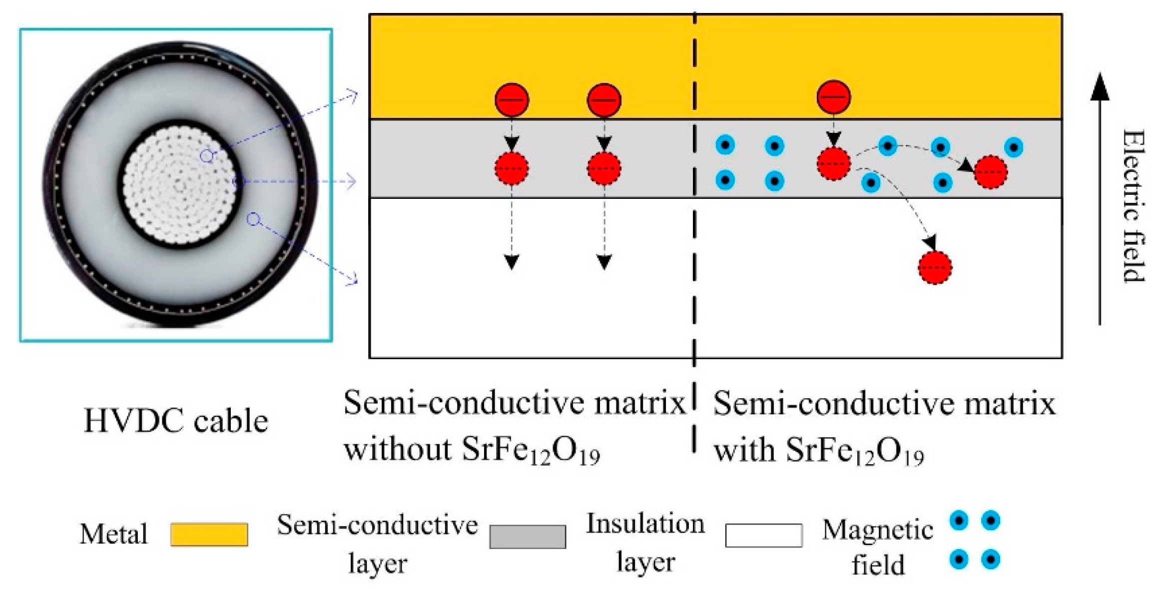
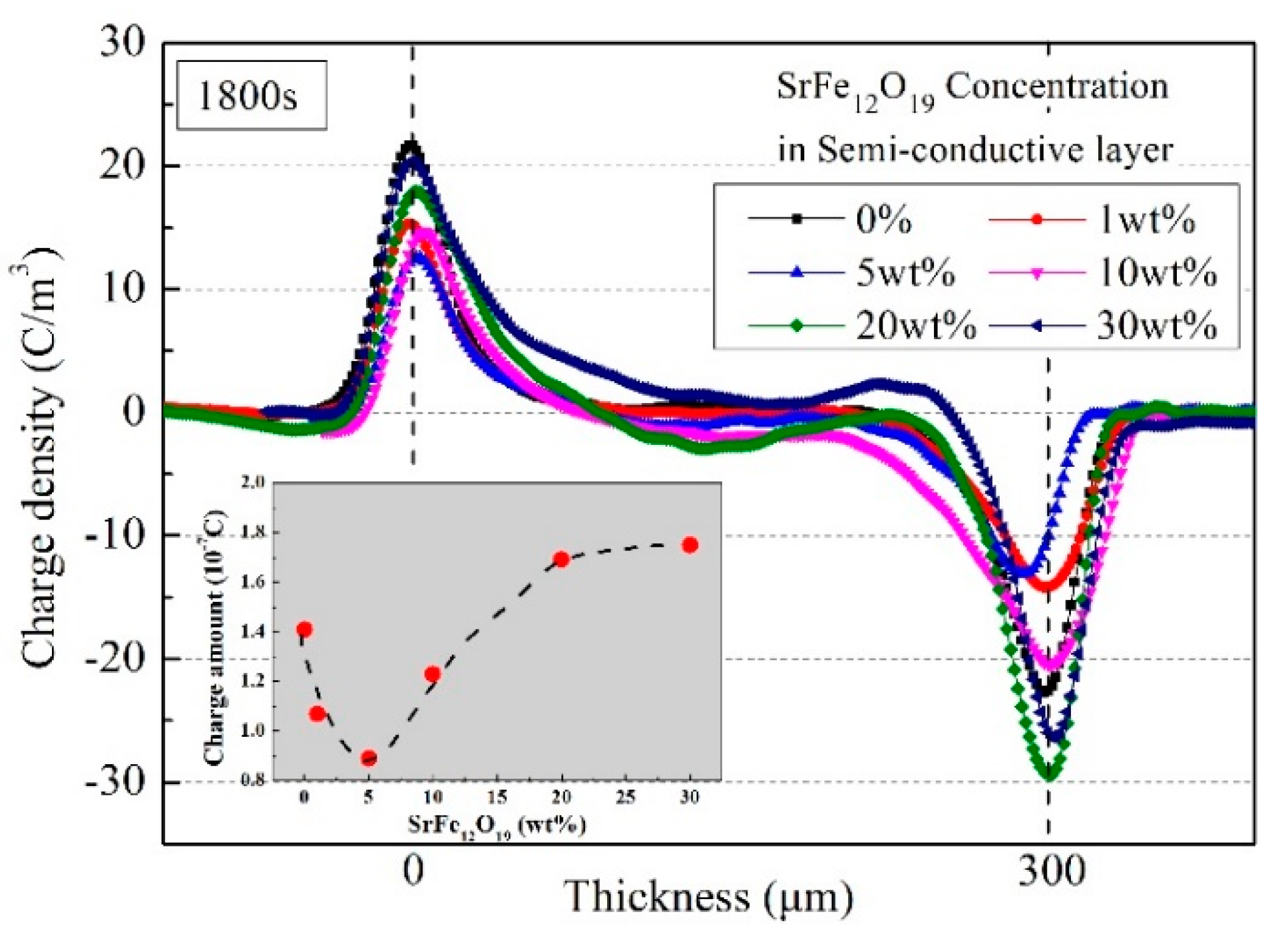
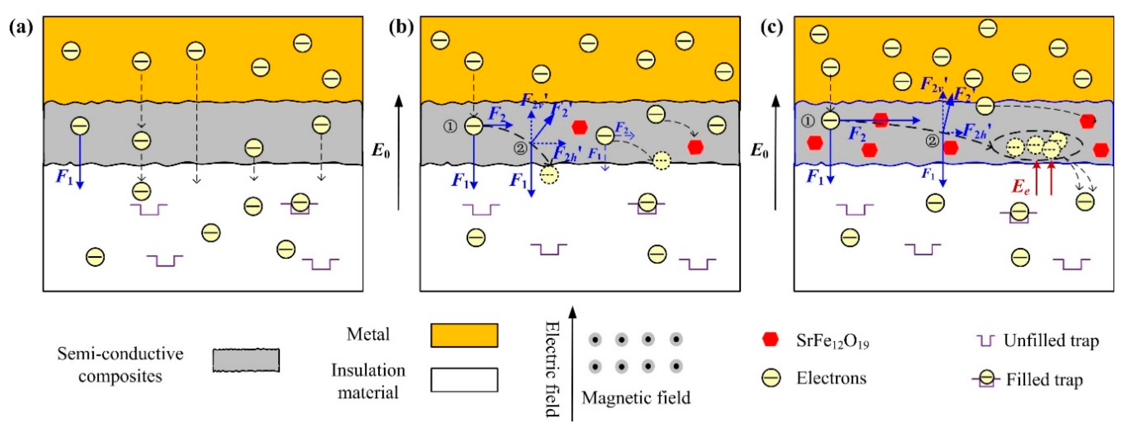
When SrFe12O19 content is low (1 wt.% and 5 wt.%), the experimental results show that the charges in the insulation sample are significantly inhibited. For SrFe12O19 content with 5 wt.%, the insulation sample has the smallest charge amount, 0.89 × 10⁻⁷ C, decreasing by 37%, and the steady-state current is 6.01 × 10⁻¹⁰ A, decreasing by 22%. This is because the moving charges will be affected by the horizontal Lorentz force, leading to the deflection of the charge migration path in SrFe12O19/semi-conductive composites. In addition, the moving charges are subjected to the electric field force in the vertical direction, and only some of the electrons enter the insulation sample.
(2)
When SrFe12O19 content exceeds 10 wt.%, the charge suppression effect is not obvious and even leads to the increase of charge amount in the insulation sample, owing to the secondary injection of charges. For high doping content, a large Lorentz force will be generated in the SrFe12O19/semi-conductive composites, and most moving charges will deflect towards the horizontal direction and cannot directly access the insulation sample, resulting in a large number of charges accumulating in the SrFe12O19/semi-conductive composites. Consequently, the interface electric field between the semi-conductive layer and the insulation sample was enhanced, leading to the secondary injection of charges.

Author Contributions

Y.W., G.L. and Q.L. put forward the idea and designed the experiments; Y.W., M.L. and J.W. implemented the experiments; G.L. and C.H. provided support for the analysis of the experimental results.

Funding

This work was funded by Shandong Provincial Natural Science Foundation, China (Grant No. ZR2019BEE036), China Postdoctoral Science Foundation (Grant No. 2018M642627), National Engineering Laboratory for Ultra High Voltage Engineering Technology (Grant No. NEL201802).

Conflicts of Interest

The authors declare no conflict of interest.

References

  1. Mazzanti, A.G.; Marzinotto, M. Extruded Cables for High-Voltage Direct-Current Transmission: Advances in Research and Development; John Wiley & Sons, Inc.: Piscataway, NJ, USA, 2013. [Google Scholar]
  2. Pleşa, I.; Noţingher, P.V.; Schlögl, S.; Sumereder, C.; Muhr, M. Properties of polymer composites used in high-voltage applications. Polymers 2016, 8, 173. [Google Scholar] [CrossRef] [PubMed]
  3. Chao, Z.; Mizutani, T.; Kaneko, K.; Tatsuo, M.; Mitsugu, I. Space charge behaviors of low-density polyethylene blended with polypropylene copolymer. Polymer 2002, 43, 2261–2266. [Google Scholar]
  4. Hoang, A.; Pallon, L.; Liu, D.; Serdyuk, Y.; Gubanski, S. Charge transport in LDPE nanocomposites Part I—experimental approach. Polymers 2016, 8, 87. [Google Scholar] [CrossRef] [PubMed]
  5. Li, G.; Wang, J.; Han, W.; Wei, Y.; Li, S. Influence of temperature on charge accumulation in low-density polyethylene based on depolarization current and space charge decay. Polymers 2019, 11, 587. [Google Scholar] [CrossRef] [PubMed]
  6. Rogti, F.; Mekhaldi, A.; Laurent, C. Space charge behavior at physical interfaces in cross-linked polyethylene under DC field. IEEE Trans. Dielectr. Electr. Insul. 2008, 15, 1478–1485. [Google Scholar] [CrossRef]
  7. Wei, Y.; Liu, M.; Han, W.; Li, G.; Hao, C.; Lei, Q. Charge injection characteristics of semi-conductive composites with carbon black-polymer for HVDC cable. Polymers 2019, 11, 1134. [Google Scholar] [CrossRef]
  8. Tanaka, T.; Okamoto, T.; Hozumi, N.; Suzuki, K. Interfacial improvement of XLPE cable insulation at reduced thickness. IEEE Trans. Dielectr. Electr. Insul. 1996, 3, 345–350. [Google Scholar] [CrossRef]
  9. Zhang, Z.; Assala, P.D.S.; Wu, L.H. Residual life assessment of 110 kV XLPE cable. Electr. Power Syst. Res. 2018, 163, 572–580. [Google Scholar] [CrossRef]
  10. Okamoto, T.; Ishida, M.; Hozumi, N. Dielectric breakdown strength affected by the lamellar configuration in XLPE insulation at a semiconducting interface. IEEE Trans. Dielectr. Electr. Insul. 1989, 24, 599–607. [Google Scholar] [CrossRef]
  11. Li, L.; Han, B.; Song, W.; Wang, X.; Lei, Q. The effect of the semiconductive screen on space charge suppression in cross-Linked polyethylene. Chin. Phys. Lett. 2014, 31, 112–115. [Google Scholar] [CrossRef]
  12. Vissouvanadin, B.; Roy, S.L.; Teyssedre, G.; Laurent, C.; Denizet, I.; Mammeri, M.; Poisson, B. Impact of concentration gradient of polarizable species on the electric field distribution in polymeric insulating material for HVDC cable. IEEE Trans. Dielectr. Electr. Insul. 2011, 18, 833–839. [Google Scholar] [CrossRef]
  13. Carstensen, P.; Farkas, A.A.; Campus, A.; Nilsson, U.H. The effect of the thermal history on the space charge accumulation in HVDC crosslinked polyethylene cables. In Proceedings of the 2005 Annual Report Conference on Electrical Insulation and Dielectric Phenomena, Nashville, TN, USA, 16–19 October 2005; pp. 381–388. [Google Scholar]
  14. Takada, T.; Hayase, Y.; Tanaka, Y.; Okamoto, T. Space charge trapping in electrical potential well caused by permanent and induced dipoles for LDPE/MgO nanocomposite. IEEE Trans. Dielectr. Electr. Insul. 2008, 15, 152–160. [Google Scholar] [CrossRef]
  15. Nelson, J.K.; Fothergill, J.C. Internal charge behaviour of nanocomposites. Nanotechnology 2004, 15, 586–595. [Google Scholar] [CrossRef] [Green Version]
  16. Lewis, T.J. Charge transport in polyethylene nanodielectrics. IEEE Trans. Dielectr. Electr. Insul. 2014, 21, 479–502. [Google Scholar] [CrossRef]
  17. Lau, K.Y.; Vaughan, A.S.; Chen, G.; Hosier, I.L.; Holt, A.F.; Ching, K.Y. On the space charge and DC breakdown behavior of Polyethylene/Silica nanocomposites. IEEE Trans. Dielectr. Electr. Insul. 2014, 21, 340–351. [Google Scholar] [CrossRef]
  18. Lau, K.; Vaughan, A.; Chen, G. Nanodielectrics: Opportunities and challenges. IEEE Trans. Dielectr. Electr. Insul. 2015, 31, 45–54. [Google Scholar] [CrossRef]
  19. Hozumi, N.; Suzuki, H.; Okamoto, T.; Watanabe, K.; Watanabe, A. Direct observation of time-dependent space charge profiles in XLPE cable under high electric fields. IEEE Trans. Dielectr. Electr. Insul. 1994, 1, 1068–1076. [Google Scholar] [CrossRef]
  20. Wang, W.; Min, D.; Li, S. Understanding the conduction and breakdown properties of polyethylene nanodielectrics: Effect of deep traps. IEEE Trans. Dielectr. Electr. Insul. 2016, 23, 564–572. [Google Scholar] [CrossRef]
  21. Wang, S. DC Insulation Performance of XLPE and Its Nano-Composites. Ph.D. Thesis, Xi’an Jiaotong University, Xi’an, China, 2017. [Google Scholar]
  22. Matsui, K.; Tanaka, Y.; Takada, T.; Fukao, T.; Fukunaga, K.; Maeno, T.; Alison, J.M. Space charge behavior in low density polyethylene at pre-breakdown. IEEE Trans. Dielectr. Electr. Insul. 2005, 12, 406–415. [Google Scholar] [CrossRef]
  23. Wang, X.; Lv, Z.; Wu, K.; Chen, X.; Tu, D.; Dissado, L.A. Study of the factors that suppress space charge accumulation in LDPE nanocomposites. IEEE Trans. Dielectr. Electr. Insul. 2014, 21, 1670–1679. [Google Scholar] [CrossRef]
  24. Delpino, S.; Fabiani, D.; Montanari, G.C.; Laurent, C.; Teyssedre, G.; Morshuis, P.H.F.; Bodega, R.; Dissado, L.A. Polymeric HVDC cable design and space charge accumulation. Part 2: Insulation interfaces. IEEE Electr. Insul. Mag. 2008, 24, 14–24. [Google Scholar] [CrossRef]
  25. Fabiani, D.; Montanari, G.C.; Laurent, C.; Teyssedre, G.; Morshuis, P.H.F.; Bodega, R.; Dissado, L.A. Polymeric HVDC cable design and space charge accumulation. Part 1: Insulation/semicon interface. IEEE Electr. Insul. Mag. 2007, 23, 11–19. [Google Scholar] [CrossRef]
  26. Roy, M.; Nelson, J.K.; Maccrone, R.K.; Schadler, L.S.; Reed, C.W.; Keefe, R.; Zenger, W. Polymer nanocomposite dielectrics-the role of the interface. IEEE Trans. Dielectr. Electr. Insul. 2005, 12, 629–643. [Google Scholar] [CrossRef]
  27. Li, Z.; Du, B.; Han, C.; Xu, H. Trap modulated charge carrier transport in polyethylene/graphene nanocomposites. Sci. Rep. 2017, 7, 4015. [Google Scholar] [CrossRef]
  28. Nilsson, U.H.; Boström, J.-O. Influence of the semi-conductive material on space charge build-up in extruded HVDC cables. In Proceedings of the 2010 IEEE International Symposium on Electrical Insulation, San Diego, CA, USA, 6–9 June 2010; pp. 1–4. [Google Scholar]
  29. Van der Born, D.; Tsekmes, A.; Person, T.J. Evaluation of space charge accumulation processes in small size polymeric cable models. In Proceedings of the 2012 Annual Report Conference on Electrical Insulation and Dielectric Phenomena, Montreal, QC, Canada, 14–17 October 2012; pp. 669–672. [Google Scholar]
  30. Han, S.J.; Wasserman, S.H. Agglomeration and percolation network behavior of semi-conductive polymer composites with carbon nanotubes. In Proceedings of the 2010 IEEE International Symposium on Electrical Insulation, San Diego, CA, USA, 6–9 June 2010; pp. 1–4. [Google Scholar]
  31. Zhang, Z.; Niu, F.; An, Z.; Zheng, F.; Ma, P.; Lei, Q. Space charge injection in LDPE by semi-conductive electrode with different carbon black filling rates. High Volt. Eng. 2011, 37, 1904–1909. [Google Scholar]
  32. Zhou, Z. Ferrite Magnetic Material. Science Press: Beijing, China, 1981. [Google Scholar]
  33. Chen, T. Study on Polyamide 6/Strontium Ferrite Composites. Master’s Thesis, South China University of Technology, Guangzhou, China, 2012. [Google Scholar]
  34. Korshak, Y.V.; Medvedeva, T.V.; Ovchinnikov, A.A.; Spector, V.N. Organic polymer ferromagnet. Am. Inst. Phys. 1987, 43, 399–402. [Google Scholar] [CrossRef]
  35. Wen, D.; Wan, Y. Technology of Preparing Isotropical Polymer-NdFeB Magnetic Composite. Actamateriae Compos. Sin. 1997, 14, 6–9. [Google Scholar]
  36. Lv, G. Influence of the Properties of the Compounding Technology on Plastics Magnet. China Synth. Resin Plast. 1990, 2, 33–36. [Google Scholar]
  37. Shashanka, H.M.; Anantharamaiah, P.N.; Joy, P.A. Magnetic parameters of SrFe12O19 sintered from a mixture of nanocrystalline and micron-sized powders. Ceram. Int. 2019, 45, 13592–13596. [Google Scholar] [CrossRef]
  38. Chen, G.; Li, S.T.; Zhong, L.S. Space charge in nanodielectrics and its impact on electrical performance. In Proceedings of the IEEE 11th International Conference on the Properties and Applications of Dielectric Materials (ICPADM), Sydney, Australia, 19–22 July 2015; pp. 36–39. [Google Scholar]
  39. Li, G.; Zhou, X.; Hao, C.; Lei, Q.; Wei, Y. Temperature and electric field dependence of charge conduction and accumulation in XLPE based on polarization and depolarization current. AIP Adv. 2019, 9, 015109. [Google Scholar] [CrossRef] [Green Version]
Figure 1. Schematic diagram of research idea. HDVC = high voltage direct current.
Polymers 11 01309 g001
Figure 2. Infrared spectrum analysis of SrFe12O19 particles before and after modification with KH550.
Polymers 11 01309 g002
Figure 3. The SEM images and element analysis of SrFe12O19/semi-conductive composites. (a) 0%; (b) 1 wt.%; (c) 5 wt.%; (d) 10 wt.%; (e) 20 wt.%; (f) 30 wt.%; (g) element analysis.
Polymers 11 01309 g003
Figure 4. Hysteresis loops of SrFe12O19/semi-conductive composites.
Polymers 11 01309 g004
Figure 5. Resistivity of SrFe12O19/semi-conductive composites versus temperature.
Polymers 11 01309 g005
Figure 6. Space charge distribution in insulation sample under the action of semi-conductive composites with different SrFe12O19 contents (a) 0%; (b) 5 wt.%.
Polymers 11 01309 g006
Figure 7. Comparison of space charge distributions at 1800 s in in insulation sample under semi-conductive composites with different SrFe12O19 contents.
Polymers 11 01309 g007
Figure 8. Polarization current in insulation sample under semi-conductive composites with different SrFe12O19 contents.
Polymers 11 01309 g008
Figure 9. Depolarization current in insulation sample under semi-conductive composites with different SrFe12O19 contents.
Polymers 11 01309 g009
Figure 10. Schematic diagram of electron moving path in the semi-conductive layer under the combined action of electric field and magnetic field. (a) Without SrFe12O19 in the semi-conductive layer; (b) low SrFe12O19 content in the semi-conductive layer; and (c) high SrFe12O19 content in the semi-conductive layer.
Polymers 11 01309 g010

