
Experimental Study on the Interlaminar Fracture Properties of Carbon Fibre Reinforced Polymer Composites with a Single Embedded Toughened Film

 ,
,  ,
,  ,
,  ,
,  and
and
Abstract
:1. Introduction
2. Materials and Methods
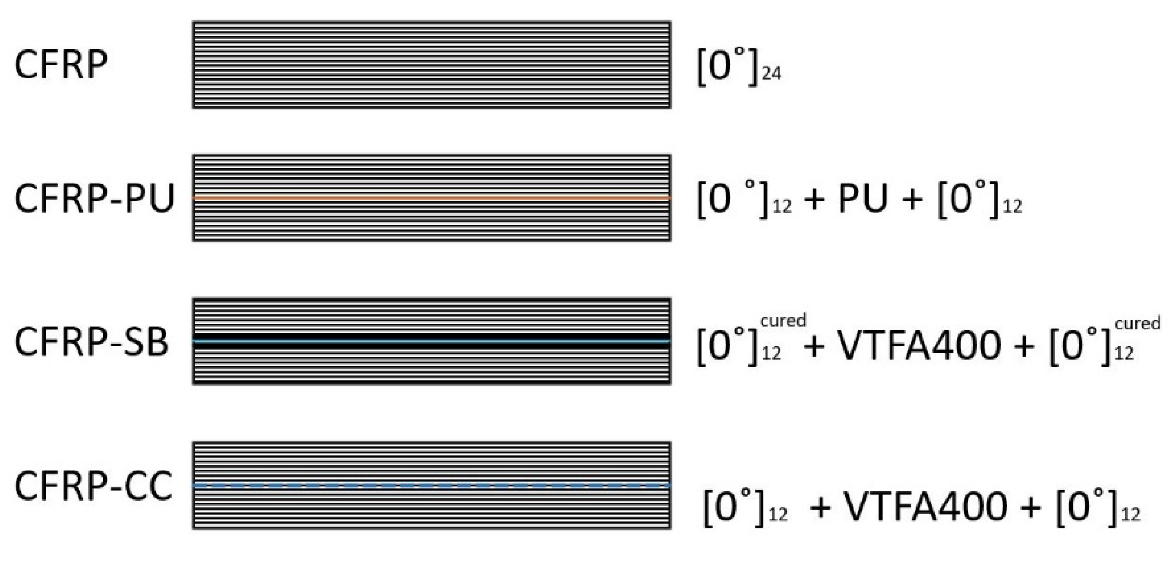
2.1. Processing and Preparation
2.1.1. Materials and Manufacturing Processes
2.1.2. Sample Preparation
2.1.3. Reliability, Accuracy and Validity
2.2. Testing
2.2.1. Double Cantilever Beam Test (DCB)
2.2.2. End Notch Flexure Test (ENF)
2.2.3. Scanning Electron Microscopy (SEM)
3. Results
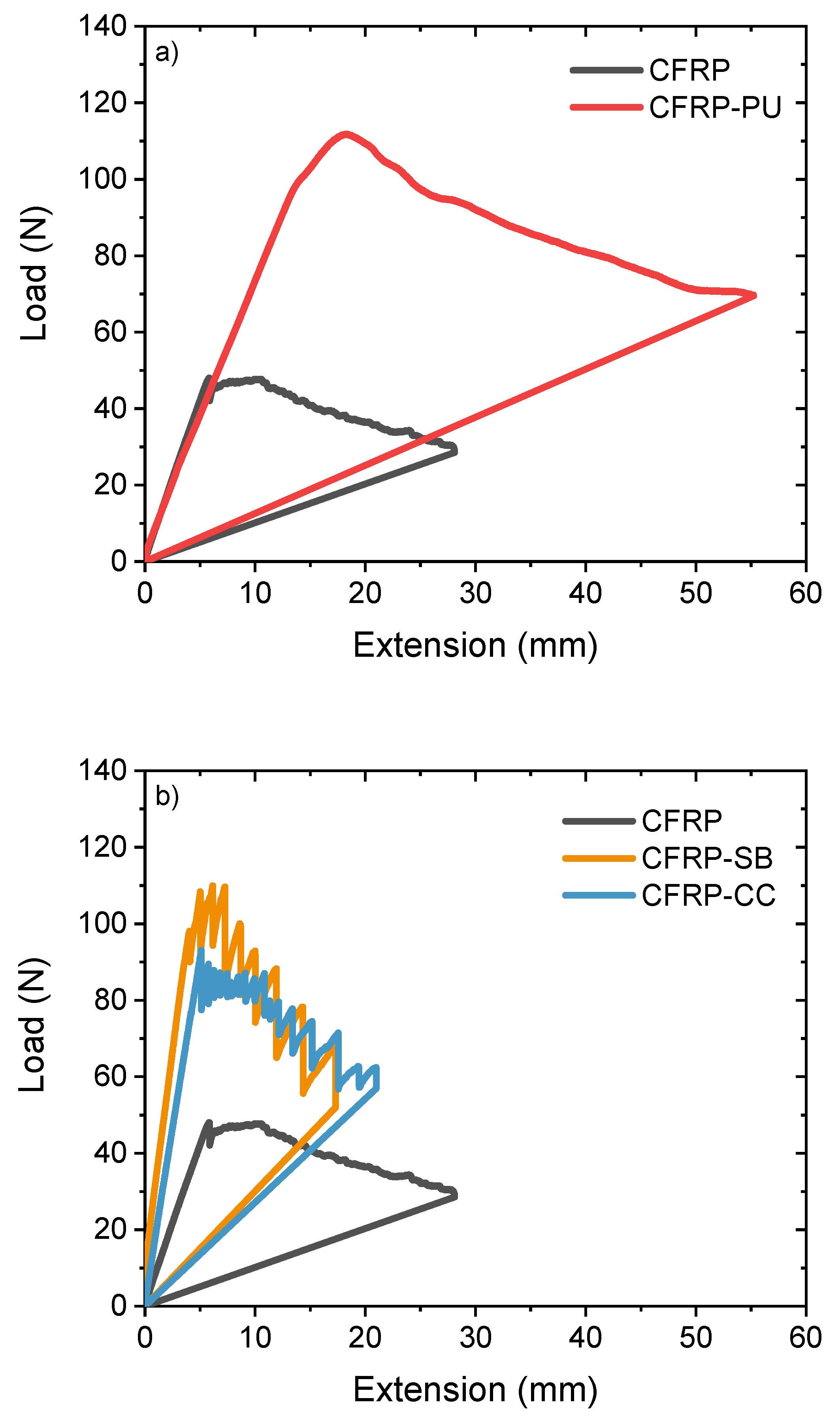
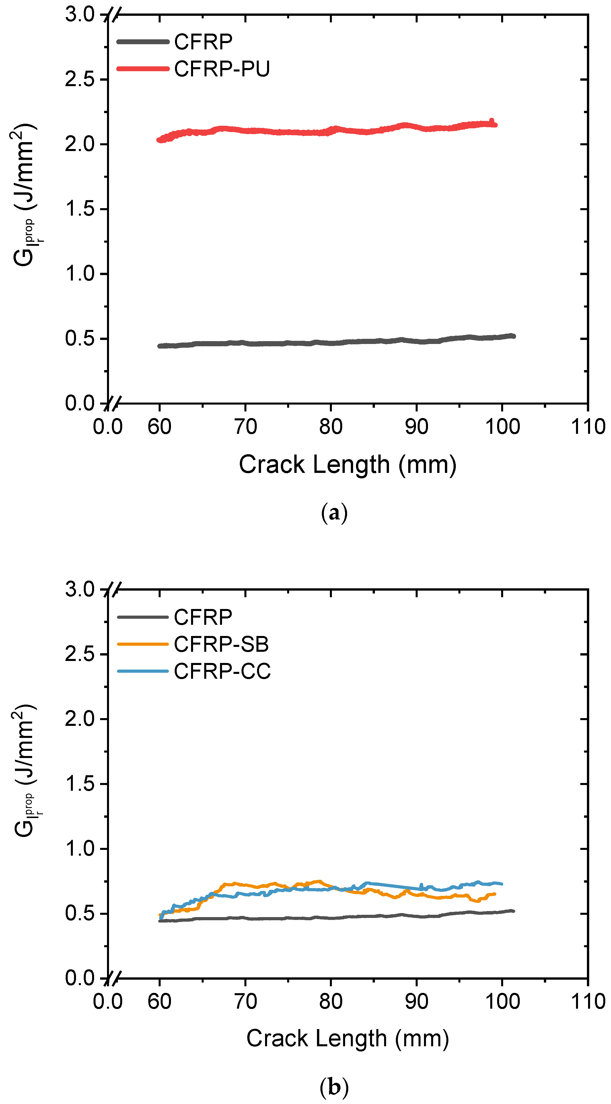
3.1. DCB Results
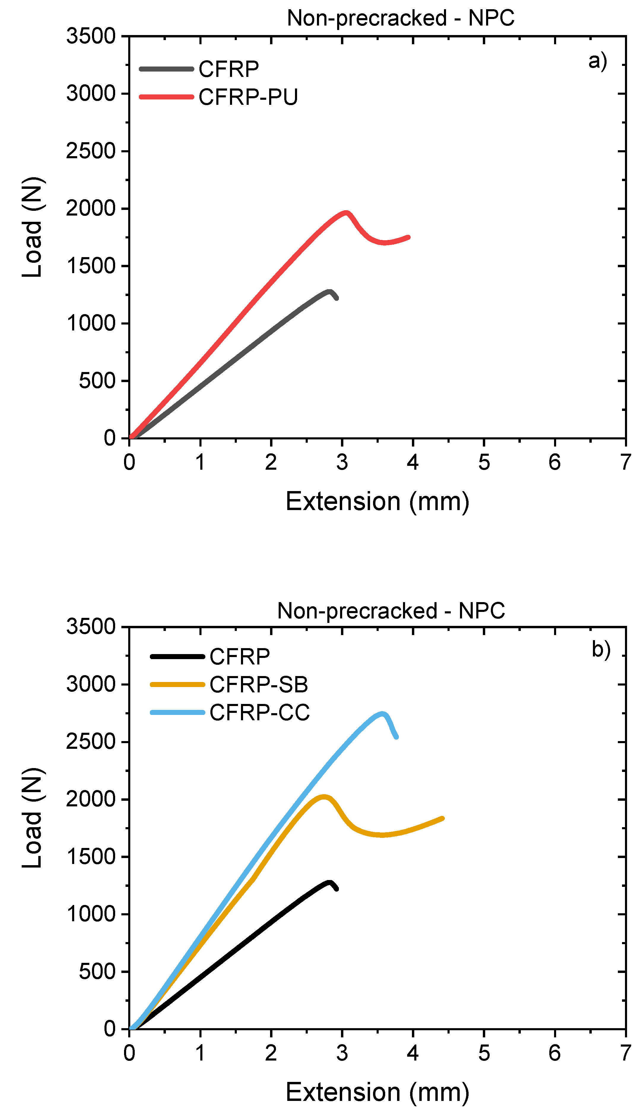
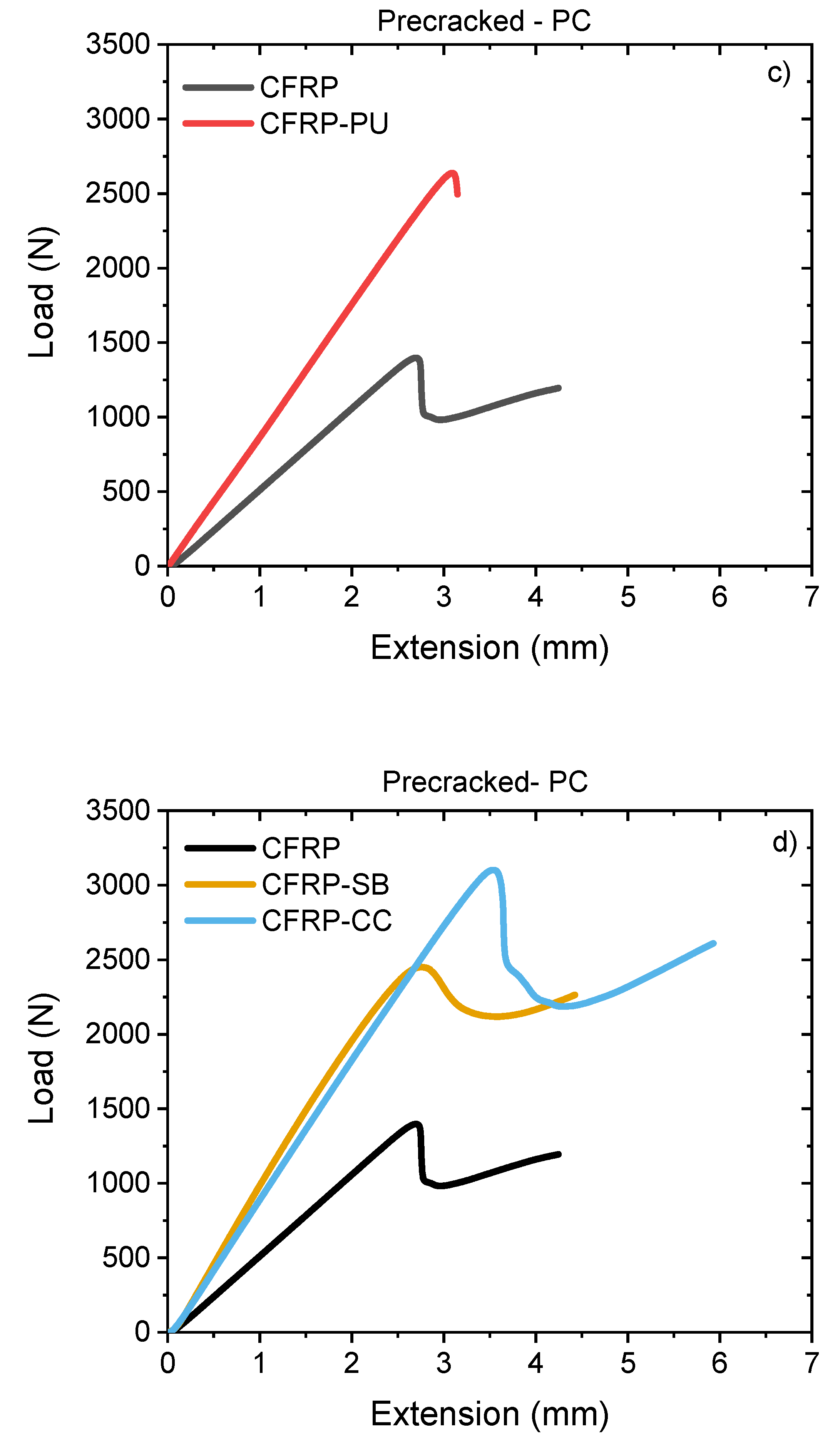
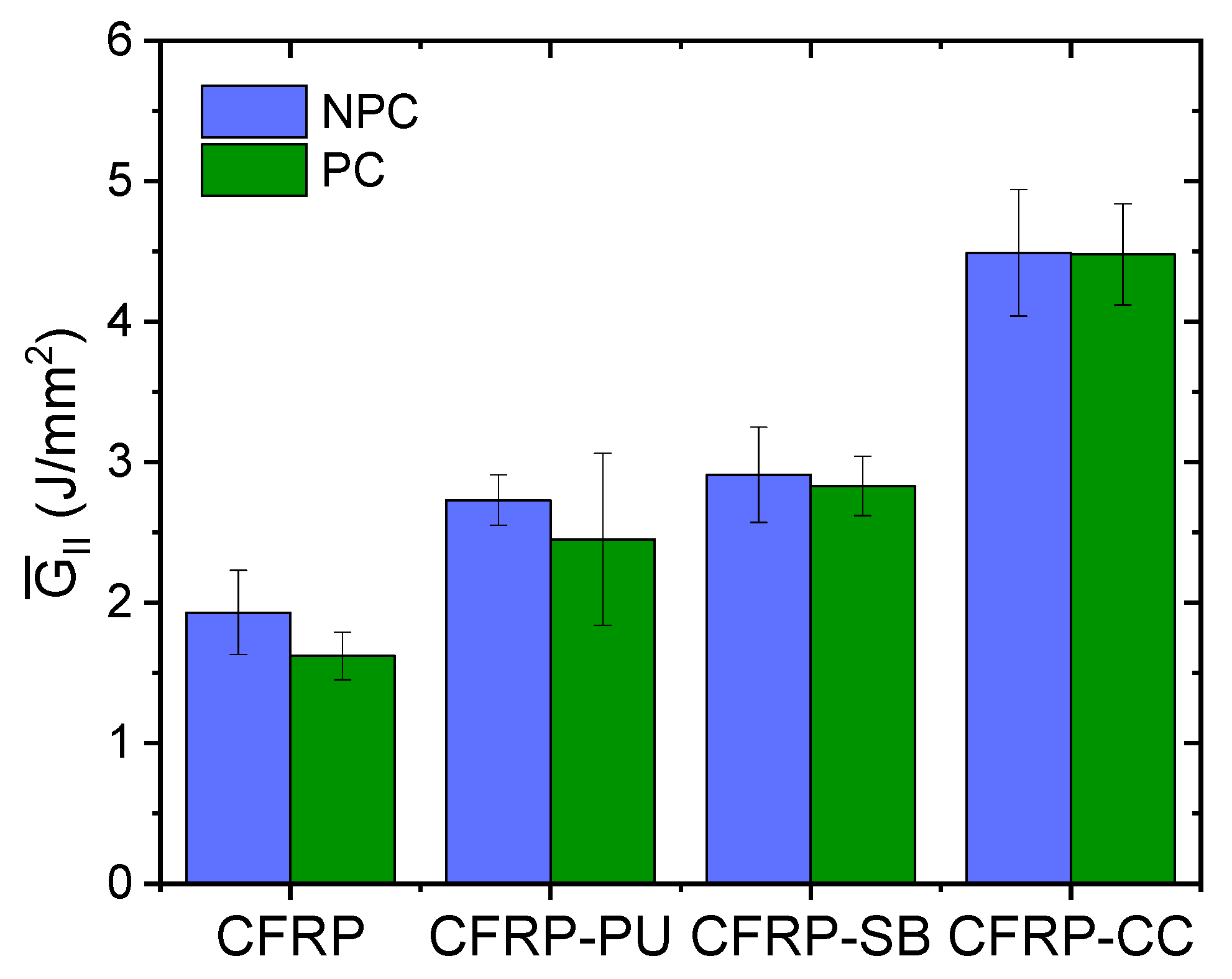
3.2. End Notch Flexure (ENF)
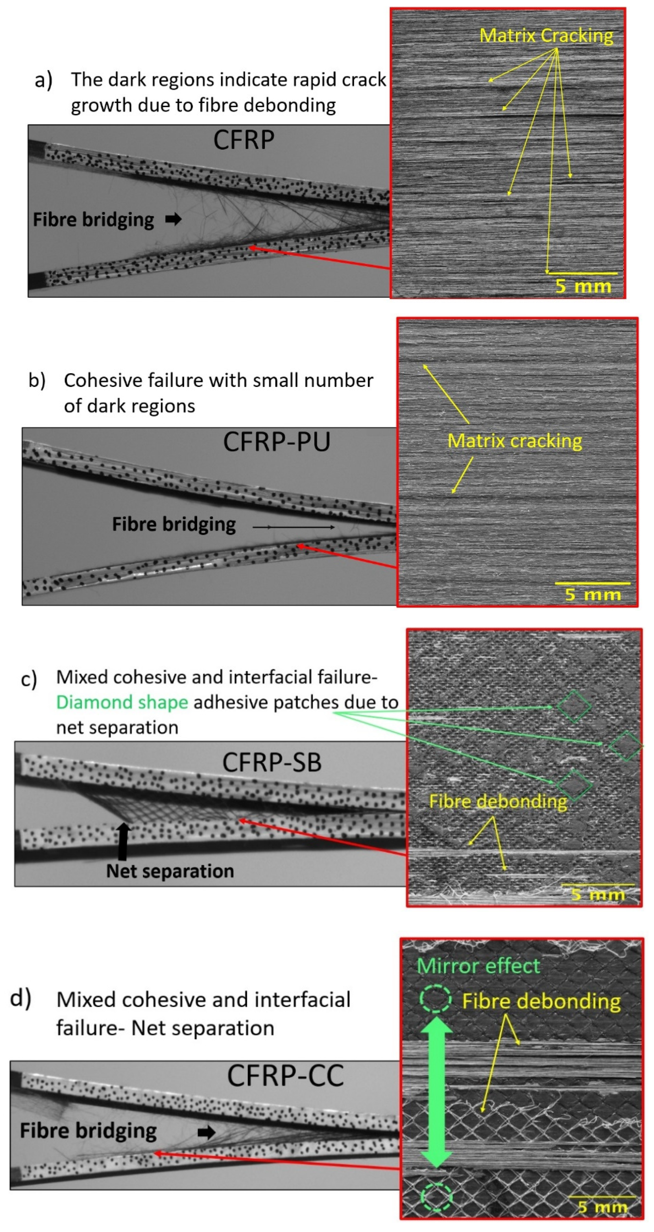
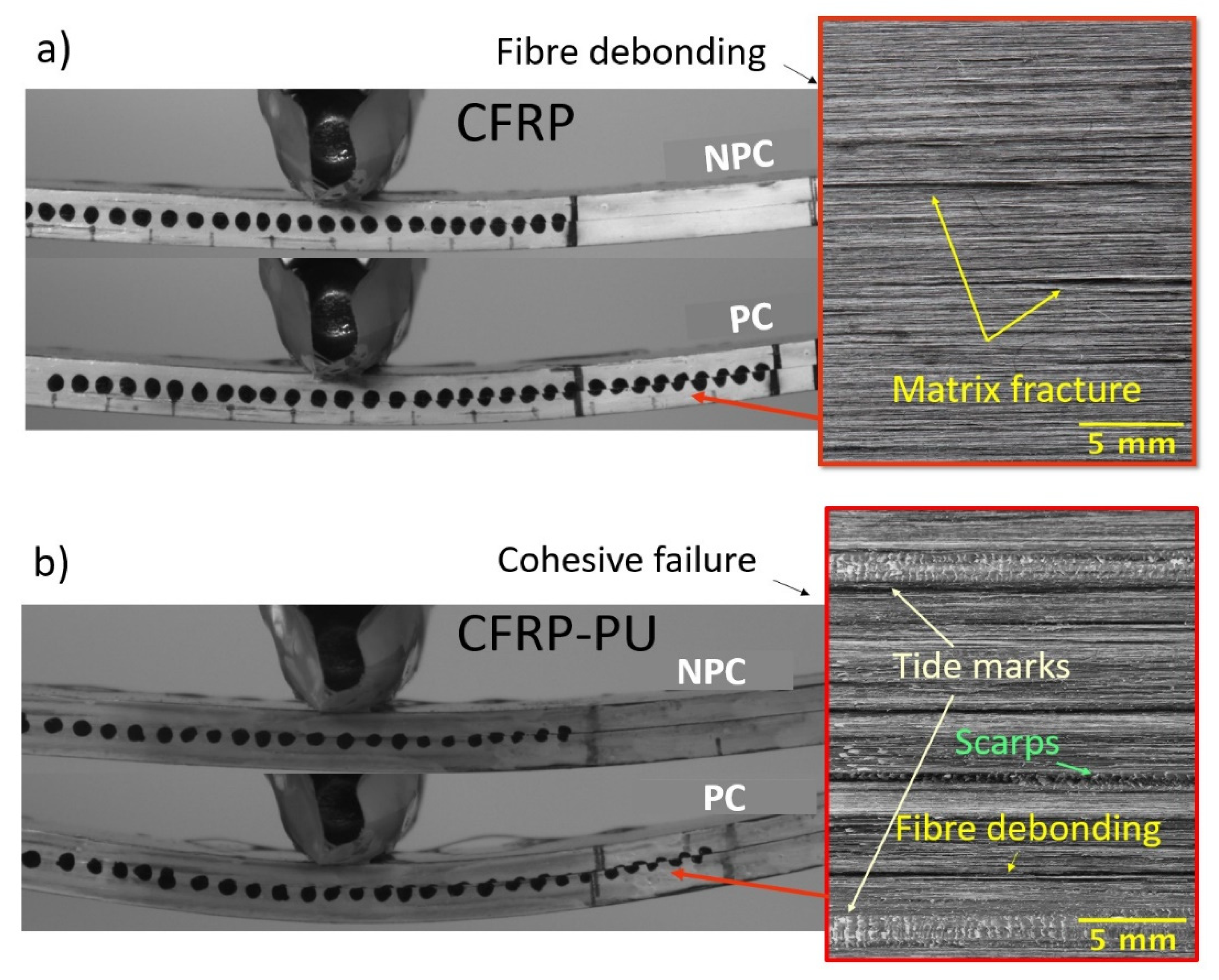
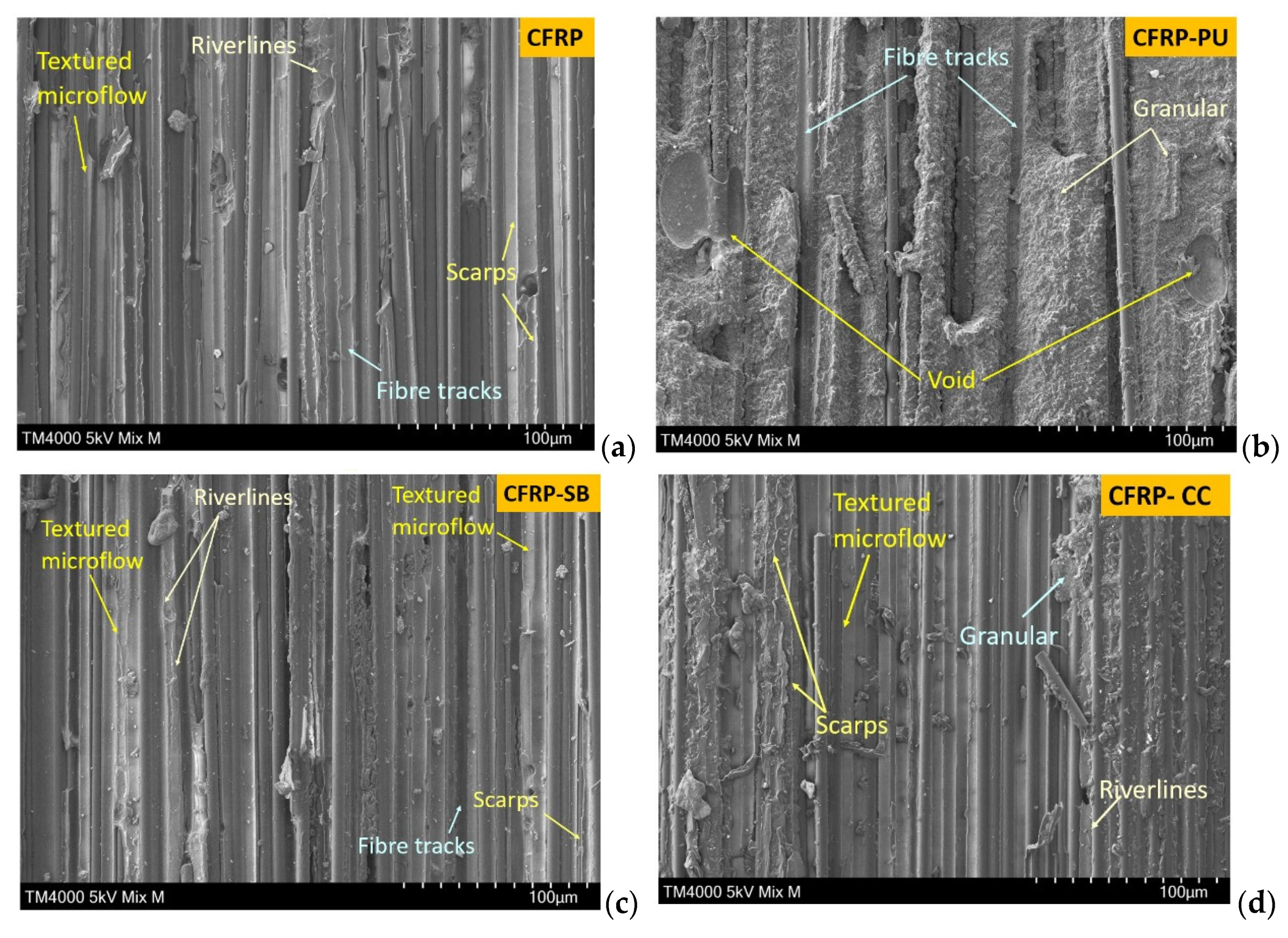
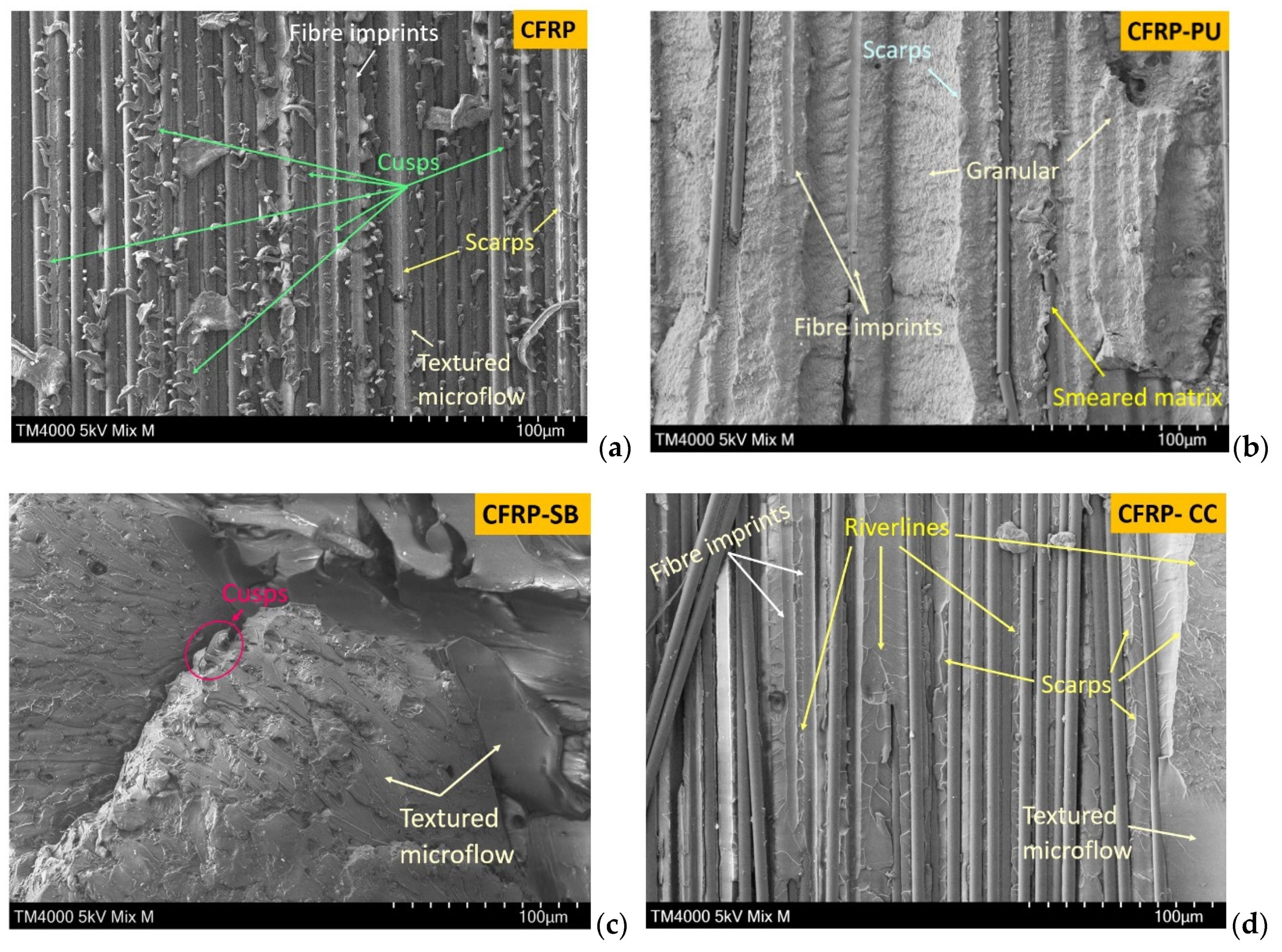
3.3. Scanning Electron Microscopy (SEM)
4. Discussion
4.1. Mode I Performance
4.2. Mode II Performance
4.3. Comparison of Co-Curing and Secondary Bonding of the Epoxy Adhesive Film
4.4. Hold and Release Mechanism of the Epoxy Film Due to the Net
5. Conclusions
Author Contributions
Funding
Institutional Review Board Statement
Informed Consent Statement
Data Availability Statement
Conflicts of Interest
References
- Graham-Jones, J.; Summerscales, J. Marine Applications of Advanced Fibre-Reinforced Composites; Woodhead Publishing: Sawston, UK, 2015. [Google Scholar] [CrossRef]
- Barbero, E.J. Introduction to Composite Materials Design, 3rd ed.; CRC Press: Boca Raton, FL, USA, 2017. [Google Scholar] [CrossRef]
- Mamalis, D.; Murray, J.J.; McClements, J.; Tsikritsis, D.; Koutsos, V.; McCarthy, E.D.; Ó Brádaigh, C.M. Novel carbon-fibre powder-epoxy composites: Interface phenomena and interlaminar fracture behaviour. Compos. Part B Eng. 2019, 174, 107012. [Google Scholar] [CrossRef]
- Clyne, T.W.; Hull, D. An Introduction to Composite Materials; Cambridge University Press: Cambridge, UK, 2019. [Google Scholar]
- Campbell, F. Structural Composite Materials; ASM International: Novelty, OH, USA, 2010. [Google Scholar]
- Staab, G.H. Laminar Composites, 2nd ed.; Butterworth-Heinemann: Oxford, UK, 2015. [Google Scholar]
- Ogin, S.L.; Brøndsted, P.; Zangenberg, J. Composite materials: Constituents, architecture, and generic damage. In Modeling Damage, Fatigue and Failure of Composite Materials, 1st ed.; Woodhead Publishing: Sawston, UK, 2016. [Google Scholar] [CrossRef]
- Camanho, P.P.; Hallett, S.R. Numerical Modelling of Failure in Advanced Composite Materials; Woodhead Publishing: Sawston, UK, 2015. [Google Scholar] [CrossRef]
- Murray, J.J.; Allen, T.; Bickerton, S.; Bajpai, A.; Gleich, K.; McCarthy, E.D.; Ó Brádaigh, C.M. Thermoplastic RTM: Impact Properties of Anionically Polymerised Polyamide 6 Composites for Structural Automotive Parts. Energies 2021, 14, 5790. [Google Scholar] [CrossRef]
- Ou, Y.; González, C.; Vilatela, J.J. Interlaminar toughening in structural carbon fiber/epoxy composites interleaved with carbon nanotube veils. Compos. Part A Appl. Sci. Manuf. 2019, 124, 105477. [Google Scholar] [CrossRef] [Green Version]
- Quan, D.; Bologna, F.; Scarselli, G.; Ivankovic, A.; Murphy, N. Interlaminar fracture toughness of aerospace-grade carbon fibre reinforced plastics interleaved with thermoplastic veils. Compos. Part A Appl. Sci. Manuf. 2020, 128, 105642. [Google Scholar] [CrossRef]
- Quan, D.; Mischo, C.; Li, X.; Scarselli, G.; Ivanković, A.; Murphy, N. Improving the electrical conductivity and fracture toughness of carbon fibre/epoxy composites by interleaving MWCNT-doped thermoplastic veils. Compos. Sci. Technol. 2019, 182, 107775. [Google Scholar] [CrossRef]
- Hamer, S.; Leibovich, H.; Green, A.; Intrater, R.; Avrahami, R.; Zussman, E.; Siegmann, A.; Sherman, D. Mode I interlaminar fracture toughness of Nylon 66 nanofibrilmat interleaved carbon/epoxy laminates. Polym. Compos. 2011, 32, 1781–1789. [Google Scholar] [CrossRef]
- Beckermann, G.W.; Pickering, K.L. Mode I and Mode II interlaminar fracture toughness of composite laminates interleaved with electrospun nanofibre veils. Compos. Part A Appl. Sci. Manuf. 2015, 72, 11–21. [Google Scholar] [CrossRef]
- Ognibene, G.; Latteri, A.; Mannino, S.; Saitta, L.; Recca, G.; Scarpa, F.; Cicala, G. Interlaminar toughening of epoxy carbon fiber reinforced laminates: Soluble versus non-soluble veils. Polymers 2019, 11, 1029. [Google Scholar] [CrossRef] [Green Version]
- Shin, Y.C.; Lee, W., II; Kim, H.S. Mode II interlaminar fracture toughness of carbon nanotubes/epoxy film-interleaved carbon fiber composites. Compos. Struct. 2020, 236, 111808. [Google Scholar] [CrossRef]
- Ning, H.; Li, Y.; Li, J.; Hu, N.; Liu, Y.; Wu, L.; Liu, F. Toughening effect of CB-epoxy interleaf on the interlaminar mechanical properties of CFRP laminates. Compos. Part A Appl. Sci. Manuf. 2015, 68, 226–234. [Google Scholar] [CrossRef]
- Cheng, C.; Zhang, C.; Zhou, J.; Jiang, M.; Sun, Z.; Zhou, S.; Liu, Y.; Chen, Z.; Xu, L.; Zhang, H.; et al. Improving the interlaminar toughness of the carbon fiber/epoxy composites via interleaved with polyethersulfone porous films. Compos. Sci. Technol. 2019, 183, 107827. [Google Scholar] [CrossRef]
- Aljarrah, M.T.; Abdelal, N.R. Improvement of the mode I interlaminar fracture toughness of carbon fiber composite reinforced with electrospun nylon nanofiber. Compos. Part B Eng. 2019, 165, 379–385. [Google Scholar] [CrossRef]
- Zheng, N.; Huang, Y.; Liu, H.Y.; Gao, J.; Mai, Y.W. Improvement of interlaminar fracture toughness in carbon fiber/epoxy composites with carbon nanotubes/polysulfone interleaves. Compos. Sci. Technol. 2017, 140, 8–15. [Google Scholar] [CrossRef] [Green Version]
- Arai, M.; Hirokawa, J.I.; Hanamura, Y.; Ito, H.; Hojo, M.; Quaresimin, M. Characteristic of mode I fatigue crack propagation of CFRP laminates toughened with CNF interlayer. Compos. Part B Eng. 2014, 65, 26–33. [Google Scholar] [CrossRef]
- Oshima, S.; Yoshimura, A.; Hirano, Y.; Ogasawara, T.; Tan, K.T. In-situ observation of microscopic damage in adhesively bonded CFRP joints under mode I and mode II loading. Compos. Struct. 2019, 227, 111330. [Google Scholar] [CrossRef]
- Ma, Y.; Yang, Y.; Sugahara, T.; Hamada, H. A study on the failure behavior and mechanical properties of unidirectional fiber reinforced thermosetting and thermoplastic composites. Compos. Part B Eng. 2016, 99, 162–172. [Google Scholar] [CrossRef]
- Arai, M.; Sasaki, T.; Hirota, S.; Ito, H.; Hu, N.; Quaresimin, M. Mixed modes interlaminar fracture toughness of cfrp laminates toughened with CNF interlayer. Acta Mech. Solida Sin. 2012, 25, 321–330. [Google Scholar] [CrossRef] [Green Version]
- Lee, S.H.; Kim, H.; Hang, S.; Cheong, S.K. Interlaminar fracture toughness of composite laminates with CNT-enhanced nonwoven carbon tissue interleave. Compos. Sci. Technol. 2012, 73, 1–8. [Google Scholar] [CrossRef]
- Moroni, F.; Pirondi, A.; Pernechele, C.; Gaita, A.; Vescovi, L. Comparative investigation of mode i and II fracture toughness of directly cured CFRP and co-cured bonded CFRP joints. Procedia Struct. Integr. 2018, 9, 86–91. [Google Scholar] [CrossRef]
- Morgado, M.A.; Carbas, R.J.C.; dos Santos, D.G.; da Silva, L.F.M. Strength of CFRP joints reinforced with adhesive layers. Int. J. Adhes. Adhes. 2020, 97, 102475. [Google Scholar] [CrossRef]
- Liu, L.; Zhang, H.; Zhou, Y. Quasi-static mechanical response and corresponding analytical model of laminates incorporating with nanoweb interlayers. Compos. Struct. 2014, 111, 436–445. [Google Scholar] [CrossRef]
- Kempf, M.; Schwägele, S.; Ferencz, A.; Altstädt, V. Effect of impact damage on the compression fatigue performance of glass and carbon fibre reinforced composites. In Proceedings of the 18th International Conferences on Composite Materials, Jeju, Korea, 21–26 August 2011. [Google Scholar]
- Kempf, M.; Skrabala, O.; Altstädt, V. Acoustic emission analysis for characterisation of damage mechanisms in fibre reinforced thermosetting polyurethane and epoxy. Compos. Part B Eng. 2014, 56, 477–483. [Google Scholar] [CrossRef]
- Kishi, H.; Kuwata, M.; Matsuda, S.; Asami, T.; Murakami, A. Damping properties of thermoplastic-elastomer interleaved carbon fiber-reinforced epoxy composites. Compos. Sci. Technol. 2004, 64, 2517–2523. [Google Scholar] [CrossRef]
- Rizzo, F.; Cuomo, S.; Pinto, F.; Pucillo, G.; Meo, M. Thermoplastic polyurethane composites for railway applications: Experimental and numerical study of hybrid laminates with improved impact resistance. J. Thermoplast. Compos. Mater. 2021, 34, 1009–1036. [Google Scholar] [CrossRef]
- Mohan, J.; Ivanković, A.; Murphy, N. Mode I fracture toughness of co-cured and secondary bonded composite joints. Int. J. Adhes. Adhes. 2014, 51, 13–22. [Google Scholar] [CrossRef] [Green Version]
- Balzani, C.; Wagner, W.; Wilckens, D.; Degenhardt, R.; Büsing, S.; Reimerdes, H.G. Adhesive joints in composite laminates—A combined numerical/experimental estimate of critical energy release rates. Int. J. Adhes. Adhes. 2012, 32, 23–38. [Google Scholar] [CrossRef] [Green Version]
- Távara, L.; Mantič, V.; Graciani, E.; Cañas, J.; París, F. Analysis of a crack in a thin adhesive layer between orthotropic materials: An application to composite interlaminar fracture toughness test. C. Comput. Model. Eng. Sci. 2010, 58, 247–270. [Google Scholar] [CrossRef]
- de Moura, M.F.S.F.; Campilho, R.D.S.G.; Gonçalves, J.P.M. Crack equivalent concept applied to the fracture characterization of bonded joints under pure mode I loading. Compos. Sci. Technol. 2008, 68, 2224–2230. [Google Scholar] [CrossRef] [Green Version]
- Mendonça Sales, R.d.C.; Brito, C.B.G.; Silveira, N.N.A.; de Souza Sena, J.L.; Arbelo, M.A.; Donadon, M.V. Hygrothermal effects on mode II interlaminar fracture toughness of co-bonded and secondary bonded composites joints. Polym. Compos. 2019, 40, 3220–3232. [Google Scholar] [CrossRef]
- Brito, C.B.G.; De Cássia Mendonça Sales Contini, R.; Gouvêa, R.F.; De Oliveira, A.S.; Arbelo, M.A.; Donadon, M.V. Mode I interlaminar fracture toughness analysis of Co-bonded and secondary bonded carbon fiber reinforced composites joints. Mater. Res. 2018, 20, 873–882. [Google Scholar] [CrossRef] [Green Version]
- Chaves, F.J.P.; Da Silva, L.F.M.; De Moura, M.F.S.F.; Dillard, D.A.; Esteves, V.H.C. Fracture mechanics tests in adhesively bonded joints: A literature review. J. Adhes. 2014, 90, 955–992. [Google Scholar] [CrossRef]
- Sarrado, C.; Turon, A.; Costa, J.; Renart, J. An experimental analysis of the fracture behavior of composite bonded joints in terms of cohesive laws. Compos. Part A Appl. Sci. Manuf. 2016, 90, 234–242. [Google Scholar] [CrossRef]
- Costa, M.; Carbas, R.; Marques, E.; Viana, G.; da Silva, L.F.M. An apparatus for mixed-mode fracture characterization of adhesive joints. Theor. Appl. Fract. Mech. 2017, 91, 94–102. [Google Scholar] [CrossRef]
- Jiang, W.; Tjong, S.C.; Chu, P.K.; Li, R.K.Y.; Kim, J.K.; Mai, Y.W. Interlaminar fracture properties of carbon fibre/epoxy matrix composites interleaved with polyethylene terephthalate (PET) films. Polym. Polym. Compos. 2001, 9, 141–145. [Google Scholar] [CrossRef]
- Vasiliev, V.V.; Morozov, E.V. Advanced Mechanics of Composite Materials and Structures, 4th ed.; Elsevier: Amsterdam, The Netherlands, 2018. [Google Scholar] [CrossRef]
- Talreja, R.; Singh, C. Review of mechanics of composite materials. In Damage and Failure of Composite Materials; Cambridge University Press: Cambridge, UK, 2012. [Google Scholar] [CrossRef]
- Zhao, L.; Wang, Y.; Zhang, J.; Gong, Y.; Lu, Z.; Hu, N.; Xu, J. An interface-dependent model of plateau fracture toughness in multidirectional CFRP laminates under mode I loading. Compos. Part B Eng. 2017, 131, 196–208. [Google Scholar] [CrossRef]
- Heu, R.; Shahbazmohamadi, S.; Yorston, J.; Capeder, P. Target Material Selection for Sputter Coating of SEM Samples. Micros. Today 2019, 27, 32–36. [Google Scholar] [CrossRef] [Green Version]
- Khan, R. Fiber bridging in composite laminates: A literature review. Compos. Struct. 2019, 229, 111418. [Google Scholar] [CrossRef]
- Kausar, A. Polyurethane/Epoxy Interpenetrating Polymer Network. In Aspects of Polyurethanes; IntechOpen: London, UK, 2017. [Google Scholar] [CrossRef] [Green Version]
- Huang, S.; Kong, X.; Xiong, Y.; Zhang, X.; Chen, H.; Jiang, W.; Niu, Y.; Xu, W.; Ren, C. An overview of dynamic covalent bonds in polymer material and their applications. Eur. Polym. J. 2020, 141, 110094. [Google Scholar] [CrossRef]
- Deng, S.; Djukic, L.; Paton, R.; Ye, L. Thermoplastic-epoxy interactions and their potential applications in joining composite structures—A review. Compos. Part A Appl. Sci. Manuf. 2015, 68, 121–132. [Google Scholar] [CrossRef]
- Matsuzaki, R.; Tsukamoto, N.; Taniguchi, J. Mechanical interlocking by imprinting of undercut micropatterns for improving adhesive strength of polypropylene. Int. J. Adhes. Adhes. 2016, 68, 124–132. [Google Scholar] [CrossRef]
- Nezhad, H.Y.; Stratakis, D.; Ayre, D.; Addepalli, S.; Zhao, Y. Mechanical performance of composite bonded joints in the presence of localised process-induced zero-thickness defects. Procedia Manuf. 2018, 16, 91–98. [Google Scholar] [CrossRef]
- Greenhalgh, E.S. Delamination-Dominated Failures in Polymer Composites; Woodhead Publishing: Sawston, UK, 2009; pp. 164–237. [Google Scholar] [CrossRef]
- Campilho, R.D.S.G.; Moura, D.C.; Banea, M.D.; Da Silva, L.F.M. Adherend thickness effect on the tensile fracture toughness of a structural adhesive using an optical data acquisition method. Int. J. Adhes. Adhes. 2014, 53, 15–22. [Google Scholar] [CrossRef] [Green Version]
- Srinivasan, K.; Jackson, W.C.; Smith, B.T.; Hinkley, J.A. Characterization of Damage Modes in Impacted Thermoset and Thermoplastic Composites. J. Reinf. Plast. Compos. 1992, 11, 1111–1126. [Google Scholar] [CrossRef]
- Boria, S.; Scattina, A. Energy absorption capability of laminated plates made of fully thermoplastic composite. Proc. Inst. Mech. Eng. Part C J. Mech. Eng. Sci. 2018, 232, 1389–1401. [Google Scholar] [CrossRef]
- Da Silva, L.F.M.; Adams, R.D. Measurement of the mechanical properties of structural adhesives in tension and shear over a wide range of temperatures. J. Adhes. Sci. Technol. 2005, 19, 109–141. [Google Scholar] [CrossRef]
- Budhe, S.; Banea, M.D.; de Barros, S.; da Silva, L.F.M. An updated review of adhesively bonded joints in composite materials. Int. J. Adhes. Adhes. 2017, 72, 30–42. [Google Scholar] [CrossRef]
- Mohan, J.; Ivanković, A.; Murphy, N. Mixed-mode fracture toughness of co-cured and secondary bonded composite joints. Eng. Fract. Mech. 2015, 134, 148–167. [Google Scholar] [CrossRef]
- Soltani, S.A.; Keshavanarayana, S.; Krishnamaraja, M.T.; Bhasin, A.; Sriyarathne, A. Effect of post-curing temperature variation on mechanical properties of adhesively bonded composite laminates. In Proceedings of the International SAMPE Technical Conference, Wichita, KS, USA, 21–24 October 2013. [Google Scholar]
- Carbas, R.J.C.; Da Silva, L.F.M.; Marques, E.A.S.; Lopes, A.M. Effect of post-cure on the glass transition temperature and mechanical properties of epoxy adhesives. J. Adhes. Sci. Technol. 2013, 27, 2542–2557. [Google Scholar] [CrossRef]
- Parvatareddy, H.; Dillard, D.A. Effect of mode-mixity on the fracture toughness of Ti-6Al-4V/FM-5 adhesive joints. Int. J. Fract. 1999, 96, 215–228. [Google Scholar] [CrossRef]


| Cases | Thickness (mm) | Density (g/cm3) | Fibre Volume Fraction (%) |
|---|---|---|---|
| CFRP | 4.02 ± 0.11 | 1.49 ± 0.01 | 51 |
| CFRP-PU | 4.03 ± 0.04 | 1.49 ± 0.02 | 50 |
| CFRP-SB | 5.00 ± 0.25 | 1.48 ± 0.02 | 51 |
| CFRP-CC | 4.66 ± 0.10 | 1.51 ± 0.01 | 54 |
| Cases | ||
|---|---|---|
| CFRP | 0.36 ± 0.08 | 1.62 ± 0.17 |
| CFRP-PU | 1.42 ± 0.15 | 2.45 ± 0.62 |
| CFRP-SB | 0.43 ± 0.11 | 2.83 ± 0.21 |
| CFRP-CC | 0.37 ± 0.07 | 4.48 ± 0.36 |
Publisher’s Note: MDPI stays neutral with regard to jurisdictional claims in published maps and institutional affiliations. |
© 2021 by the authors. Licensee MDPI, Basel, Switzerland. This article is an open access article distributed under the terms and conditions of the Creative Commons Attribution (CC BY) license (https://creativecommons.org/licenses/by/4.0/).
Share and Cite
Pappa, E.J.; Quinn, J.A.; Murray, J.J.; Davidson, J.R.; Ó Brádaigh, C.M.; McCarthy, E.D. Experimental Study on the Interlaminar Fracture Properties of Carbon Fibre Reinforced Polymer Composites with a Single Embedded Toughened Film. Polymers 2021, 13, 4103. https://doi.org/10.3390/polym13234103
Pappa EJ, Quinn JA, Murray JJ, Davidson JR, Ó Brádaigh CM, McCarthy ED. Experimental Study on the Interlaminar Fracture Properties of Carbon Fibre Reinforced Polymer Composites with a Single Embedded Toughened Film. Polymers. 2021; 13(23):4103. https://doi.org/10.3390/polym13234103
Chicago/Turabian StylePappa, Evanthia J., James A. Quinn, James J. Murray, James R. Davidson, Conchúr M. Ó Brádaigh, and Edward D. McCarthy. 2021. "Experimental Study on the Interlaminar Fracture Properties of Carbon Fibre Reinforced Polymer Composites with a Single Embedded Toughened Film" Polymers 13, no. 23: 4103. https://doi.org/10.3390/polym13234103