1. Introduction
The development of lightweight composites with high tensile strength is gaining increasing attention by the industry in several sectors due to their versatility for numerous applications. As far as the construction industry is concerned, many composites, such as unreinforced concrete, have good compressive strength and poor tensile strength. However, by adding a reinforcing component, the tensile and flexural properties can be expected to improve. Textile reinforced concrete (TRC) has several advantages: tensile strength, good flexibility, low weight, low thickness, and corrosion resistance [
1,
2]. These advantages make them very appealing to the market for construction materials. However, their potentialities and limitations have not been fully explored yet, especially when the textile reinforcement is used in combination with special types of cements such as low-emission calcium aluminate cements. For this reason, this study aims to contribute to deepening the knowledge on these types of cementitious composites, on their tensile properties and on the factors that may affect them.
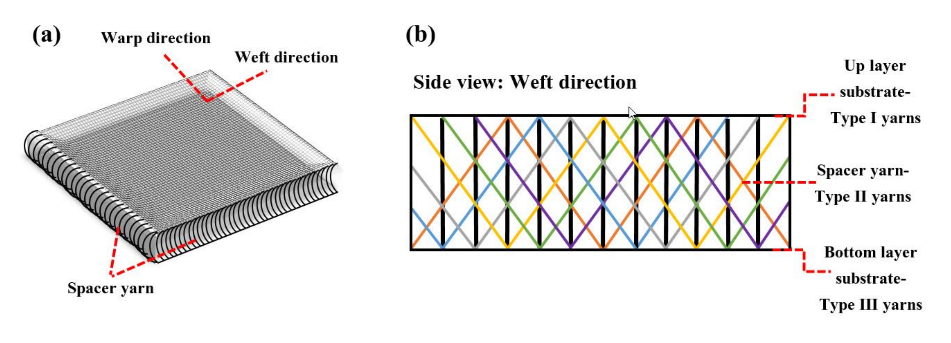
Reinforced cementitious composite with 3D fabric consists of spacer fabric and cementitious material. Spacer fabrics consist of two parallel fabrics connected by spacer yarns. The use of 3D fabrics, due to low weight and high volume, entailed the occupation of a large proportion of the overall cementitious composites, reduced the material consumption and, as a result, significantly reduced the weight of the composites. Reducing the consumption of materials is economical. On the other hand, usually, if too much bending or tensile load is applied, TRC composites will break but will not separate due to the bridging effect of fibers or fabric.
Previous studies have shown that a variety of textiles have effectively reinforced concrete matrices. The use of fibers [
3,
4], yarns, and fabrics (2D [
5,
6], 3D [
7,
8]) are among the most commonly used cementitious mortar reinforcements. Armakan and Roye [
9] investigated the use of 3D fabrics to reinforce concrete and the compressive behavior of reinforced concrete. They found that the compressive strength decreased by reducing the angle of placement of the spacer yarns and when reducing the number of these yarns. Munck et al. [
10] investigated similar specimens made from a combination of special materials using premix mortar with multiple layers of alkali-resistant (AR) fiberglass fabrics. The obtained results by [
10] showed that cracks formed at lower stress levels after being subjected to environmental loading. CC reinforced with 3D fabric with a high strain rate was also investigated [
7]. Some studies used an outer reinforcement layer by a fiber-reinforced polymer (FRP) to improve cementitious composites’ tensile and flexural strengths. The high tensile and shear strengths of FRP-reinforced CC compared with the shotcrete offered greater protection against the risk of landslides in complex situations and emergencies. FRP-reinforced CC significantly improved the safety factor due to its high tensile strength [
11]. The tensile and flexural behaviors of reinforced CCs were investigated by uniaxial tensile and four-point bending tests in two directions of weft and warp. Experimental results showed that tensile and flexural properties, in particular flexural strength, were significantly improved in reinforced CC samples [
12]. Haik et al. [
13] investigated the effect of 3D fabric orientation on the flexural properties of CC. They found that the flexural strength of 3D fabric-reinforced composites is more significant in the weft direction. Amzaleg et al. [
14] investigated the flexural strength of four-point CC reinforced with 3D warp knitted fabrics and found that the flexural strength and elongation at break of 3D fabric consisting of aramid yarns was greater than 3D polyester fabric. Hui Li et al. [
15] investigated the mechanical properties of reinforced cementitious composites with 3D warp knitted fabric. To improve the tensile strength of the composites, they used a modified ultra-high molecular weight polyethylene layer containing carbon nanotubes (CNT). Michael et al. [
16] studied the tensile and flexural properties of CC reinforced with 3D fabrics. They found that the spacer yarns did not significantly affect the tensile behavior of TRC and the number of cracks caused by bending.
With regard to the types of cement, most researchers use Portland cement because of its low cost and greater availability. Still, recently, calcium aluminate cement (CAC) has been widespread. CAC is a particular type of cement considered in CC due to its unique properties [
15]. In these composites, CAC is used as an adhesive in the mortar instead of ordinary Portland cement (OPC) [
17,
18]. Research on CAC has increased significantly over the past decades. This interest is due to the many applications of calcium aluminate cement composite (CACC) in various structures such as industrial sidewalks, wastewater treatment plants, tunnels, and oil rigs, the durability of which is of great importance [
18,
19]. CACC has several apparent advantages over ordinary Portland cement composite (OPCC), including the higher rate of compressive strength development during the setting and curing process, increased wear resistance, resistance to sulfate attacks, and alkaline-silicate reactions [
20]. In addition, CAC production results in less CO
2 emissions than OPC production [
20]. At present, CACs are mainly used in refractory cement and building chemical applications, such as quick-setting mortars [
21]. According to the results obtained by previous researchers, during the process of setting and curing of CAC mortar, when the “inversion” occurs, the strength of the CAC mortar gradually drops after it initial increased is observed [
22,
23]. The duration and speed of this process depend on the amount and constitution of the hydrated phase, environment temperature (i.e., curing age and humidity), and the existence of such a phenomenon goes back to the CAC hydration compositions [
24,
25,
26]. However, to balance the benefits of CAC, when the “inversion” phenomenon happens, denser stable hydrates in mortar media are formed with the release of water and consequent formation of porosity, which significantly reduces the mechanical strength [
27,
28]. CAC releases a lot of heat in the first 24 h of hydration, which can have a significant exothermic effect [
29]. The hydration product at low-temperature values (below 29 °C) is CAH
10 (where C = CaO, A = Al
2O
3 and H = H
2O, according to the notation chemistry of cements), which is thermodynamically unstable. With increasing temperature (between 30 to 70 °C), the product C
2AH
8 is semi-stable. At a temperature of more than 70 °C, the product C
3AH
6 is stable. Changing the phase from the unstable to the stable one reduces the volume and increases the porosity, thus reducing the strength [
21]. In various studies, temperature ranges for phase stability were different; some studies report temperature values below 10 °C for the unstable state, between 10 and 20 °C for the semi-stable one, and temperature values above 30 °C set to the stable phase [
23]. In other studies, values below 15 °C led to an unstable phase, between 15 and 30 °C to a semi-stable one, and above 45 °C to a stable one [
9,
10,
11].
Due to the effect of the water-to-cement ratio on the hydration rate [
30] and cracking ability [
31], many studies have investigated this ratio. The majority of researchers agree that the optimal ratio of water to cement is around 0.4 [
30,
31,
32,
33]. Phillips and Zhang [
34] found that the compressive strength decreases with increasing water-to-cement ratio because the evaporation of water not used in the hydration process with time leads to porosities in the concrete microstructure. It can ultimately reduce the ultimate compressive strength of concrete [
35,
36].
As mentioned, cement mortar has low tensile strength and fracture strain; therefore, TRC technology is used to reinforce cement mortar. Due to the spacer yarns, the reinforcement of cement mortar by knitted 3D fabrics has received much attention in the fabric structure. The role of using knitted 3D fabrics with spacer yarns on a smaller scale is similar to the position of using reinforcement to reinforce a concrete structure. Three-dimensional fabric acts as a reinforcing component that significantly improves the tensile strength. In addition to the type of fibers, the structure of the textiles, including yarn density, loop structures [
37], 3D fabric thickness, density [
38], and the placement angle of monofilament spacer yarns [
9,
39], count and Young’s modulus of yarns [
40] can significantly affect the reinforcement. Hesami et al. [
41] found that some energy is absorbed if the loops are easily displaced and deformed by any applied force. According to previous studies, to improve the tensile properties of cementitious composites, it was found that 3D fabrics with CAC mortar help to increase the tensile strength and decrease the setting time. Moreover, it will make the CC usable in less time.
Based on the considerations reported above regarding the potential benefits and possible influencing factors of 3D fabric-reinforced cementitious composites using calcium aluminate cement, the calcium aluminate cement was considered because of its higher strength at an early age. Because the inversion effect is important and unavoidable in calcium aluminate cement, the simultaneous effects of temperature and curing age in CAC mortar are investigated. In this regard, since 3D weft-knitted fabric machines are cheaper and easier to access than 3D warp-knitted fabric machines, therefore, in this study, the 3D weft-knitted fabric was used instead of a warp-knitted one, in addition to the effect of three different hole patterns (stitch structures) of the upper layer of the 3D fabrics in warp and weft directions on the tensile properties of the composite.
3. Results and Discussion
In this section, the results are discussed in four different parts. The first part is focused on the tensile properties of different yarns, and the second investigates the tensile strength of the fabrics of the bottom and the top layer of the 3D fabric. Part 3 investigates the cement mortar properties under tension, and in the final section, the textile-reinforced cementitious composites obtained from the 3D fabric filled with CAC mortar, after curing at different ages, were tested to investigate the effect of temperature and curing ages on the tensile properties of the CCs.
3.1. Tensile Properties of Yarn
The results of the different yarn’s (i.e., warp/weft and spacer yarns) tensile tests are summarized in
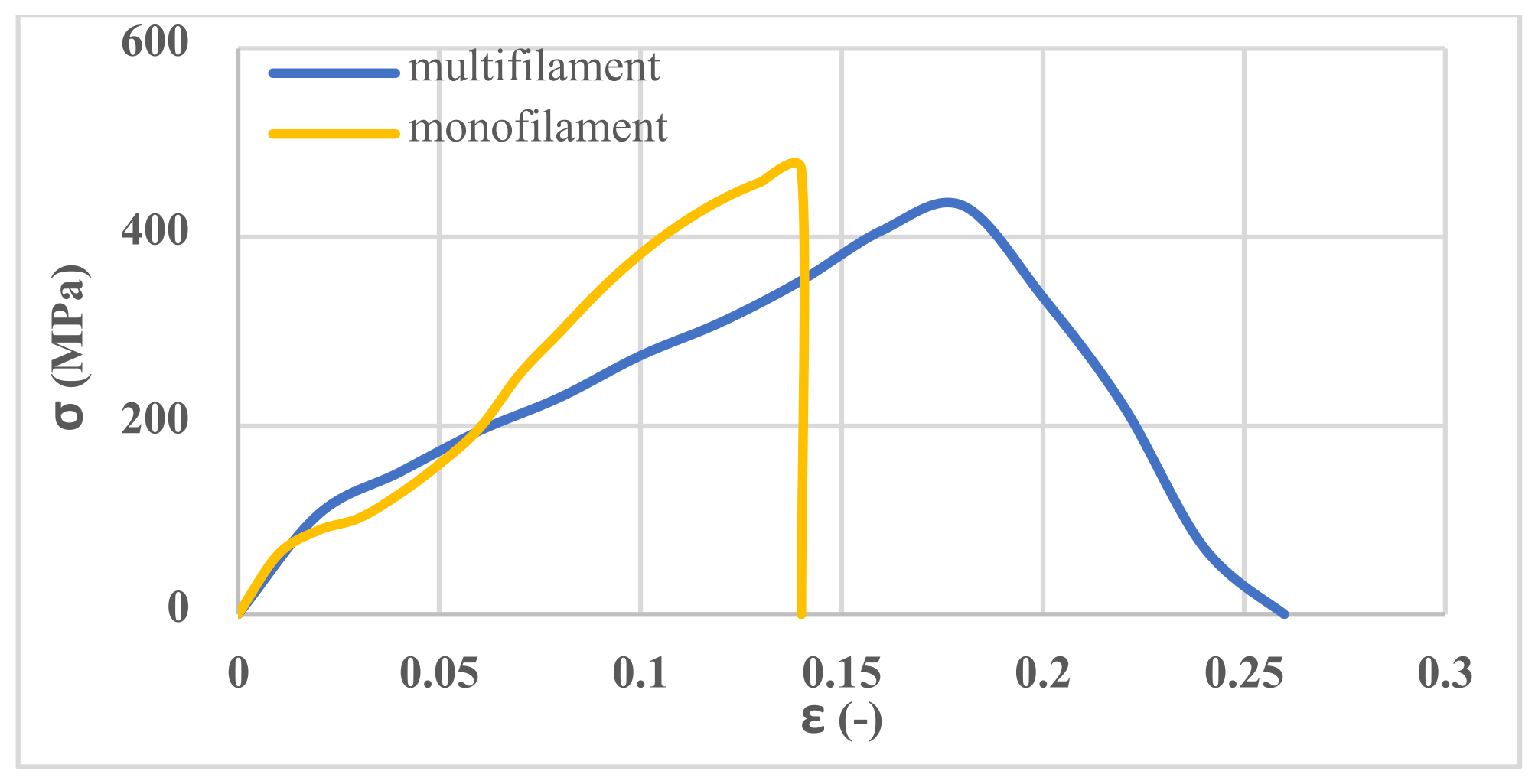
Table 4. The results showed that the tensile strength of the monofilament yarns is the same in all three types of 3D fabrics. In addition, the tensile strength of multifilament yarns forming the top layers of the outer substrate of 3D fabric are the same in all three-fabric types.
The spacer yarns provide a high stiffness to the 3D fabric. Therefore, by adding cementitious material into the 3D fabric from bottom-layer holes, despite the high weight of cementitious materials, the 3D fabric is not compressed, and its thickness does not decrease. Therefore, there is no space between the cementitious material and the layers of fabric. During the tensile test, the interaction of the tensile capacity of the spacer yarns and the upper/bottom layers of fabric are considered together. Therefore, the difference between the stiffness of the spacer yarns and the upper and bottom layers yarns should not be significant so as not to tear the stitches. Thus, the tensile Young’s modulus of the spacer yarn was about twice that of the yarn of the upper and bottom layers.
The stress–strain curve for monofilament and multifilament yarns is shown in
Figure 5.
3.2. Tensile Properties of 3D Fabrics
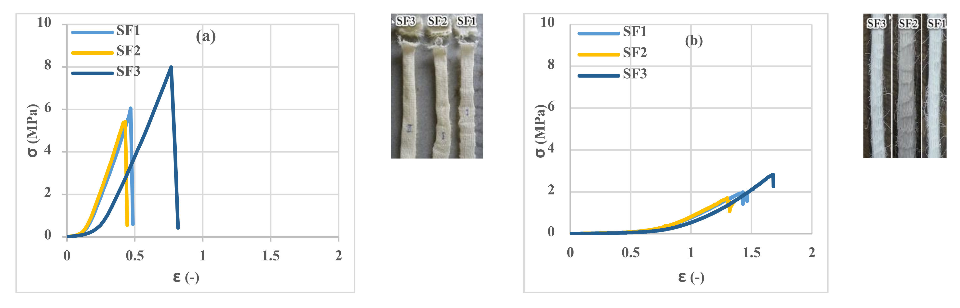
The tensile results of 3D fabrics in terms of warp and weft directions are shown in
Figure 6. At the beginning of the tensile test, due to the deformation of the loops in the fabric structure and the elongation of the loops, a considerable strain under the pre-load is observed in the fabric stress–strain curves. As the stretching process continued and sustained tensile force by yarns, the width of the fabric samples in the direction perpendicular to the tensile axis decreased, and the force increased. The results showed that the tensile strength of the three types of 3D fabrics is different due to the different stitch structures of the fabrics. As shown in
Figure 6, the tensile strength of the SF2 in the warp and weft directions is the lowest, and the SF3 is the highest with an approximately 50% higher value than the SF2. In addition, the fracture and ultimate strain of the SF2 are less than the SF1 and SF3, and therefore, this type of fabric has less energy absorbance than the others. By applying tension force to the fabric in the weft direction and according to the type of connection of the monofilament spacer yarns, these yarns provide less freedom of movement to the fabric, so in a relatively low strain, much stress is applied to the fabric. The fabric is torn from a specific point, usually from the beginning or end of the fabric, and near the tensile test setup clamps. However, a considerable strain was observed by applying tension to the fabric at the warp direction due to the greater freedom for the movement of the monofilament spacer yarns. In the tensile test of the fabric in the warp direction, several weft yarns usually come together, and tear occurs along with the sample. By comparing the first and second parts of
Figure 6, it can be concluded that the tensile strength of 3D fabrics in the weft direction is higher than the warp direction. In addition, the fracture and the ultimate strain of 3D fabrics in the warp direction are higher than in the weft direction. Therefore, it can be concluded that the different stitch structures of the fabric influenced the tensile strength of the 3D fabric.
3.3. Investigation of Cement Phase Properties in Tension
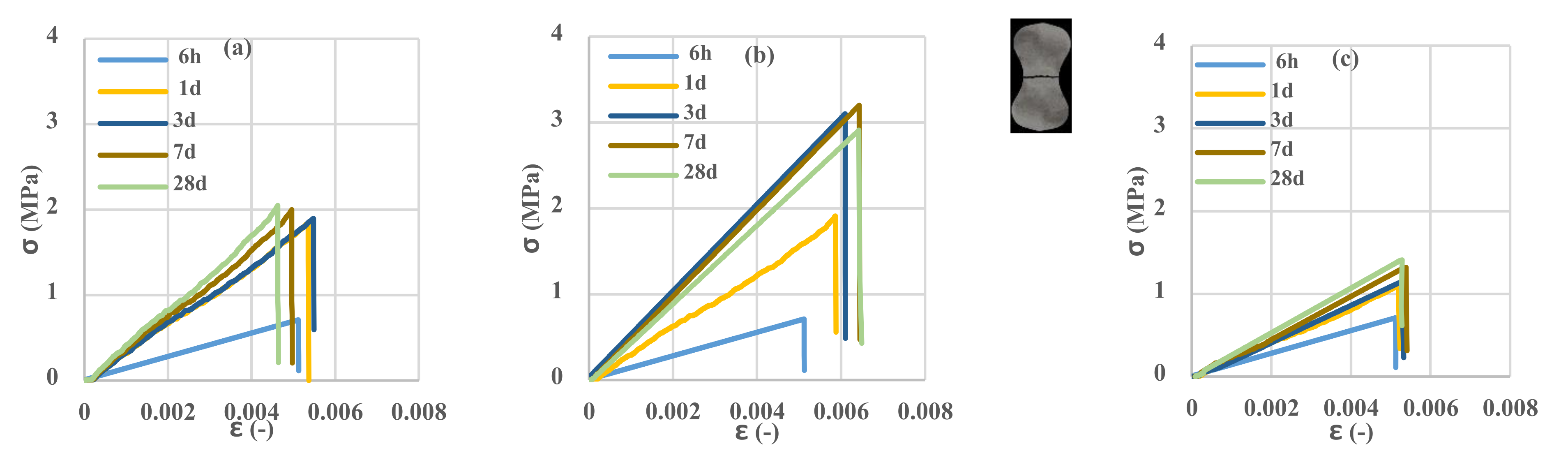
To evaluate the influence of the temperature and curing age of cement mortar specimens on the tensile strength, cement mortar samples in standard molds were prepared and tested. The results in
Figure 7 show that the specimens are entirely broken with just one crack. It is observed that the trend of changes in the strength of cement mortar at a specific temperature is different so that at 7 and 50 °C, with increasing the age of the samples, tensile strength increases; however, at 23 °C, after 7 days, the process of reaching strength is reversed to 28 days. The phenomenon of inversion is visible at this temperature. According to Juenger’s research [
21], at 7 °C, the probability of inversion is much higher than at 23 °C, but due to the decrease in hydration speed, this effect is expected to be visible after 28 days. However, according to various researchers [
9,
11,
23], the increase in temperature is so effective in reducing this phenomenon that this effect was not observed at 50 °C. As shown in the results, the behavior of the cement mortar in terms of maximum tensile strength and fracture strain at 50 °C is lower than the behavior of the mortar at low and medium temperature values. Changing the material structure at high temperature from the unstable phase of CAH
10 to the stable phase of C
3AH
6 has weakened the molecular structure and thus reduced the hardness of the material and the ultimate tensile strength. This result is consistent with the result of Juenger’s research [
21].
3.4. Tensile Behavior of Reinforced Cementitious Composites
In this section, the tensile performance of reinforced cementitious composite is presented in
Figure 8.
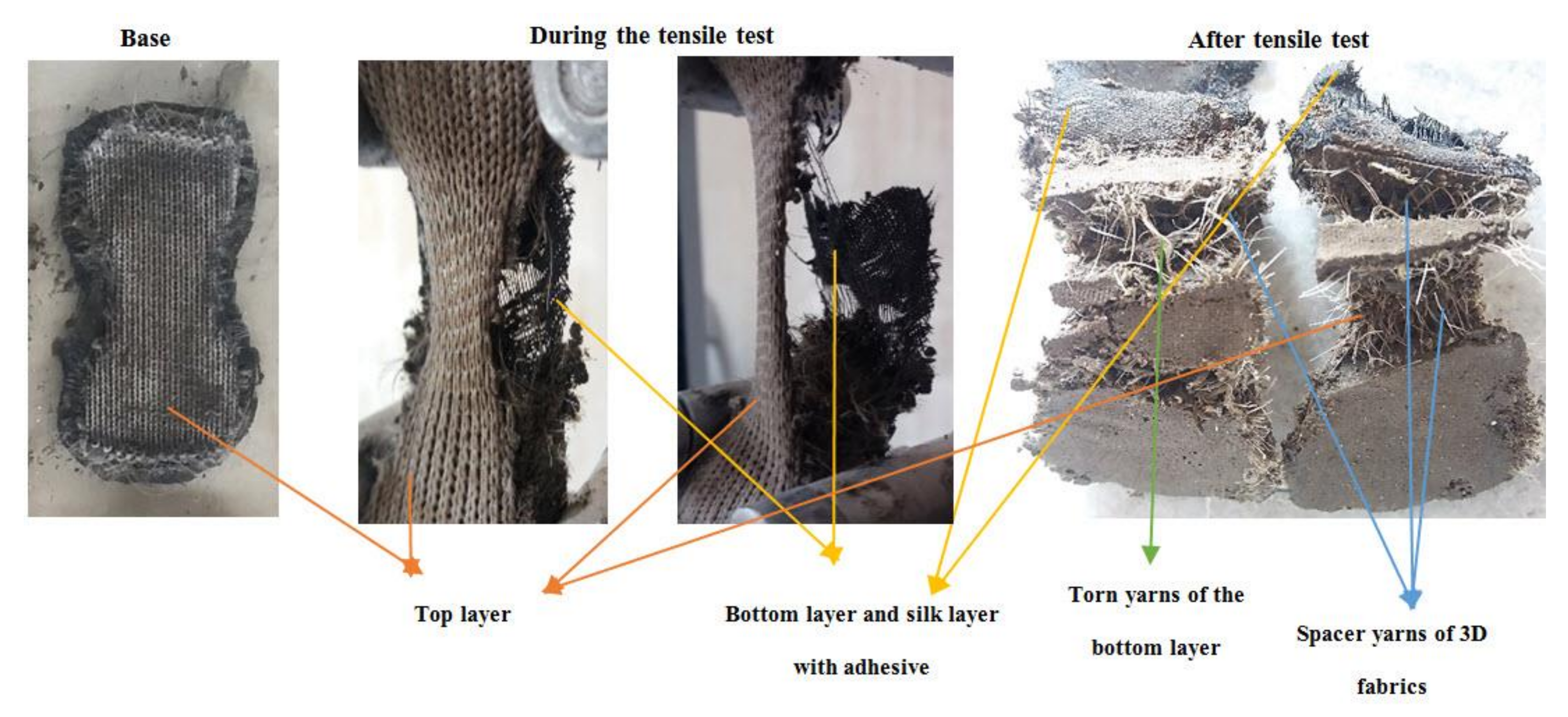
Figure 8 shows the CC components reinforced with 3D fabric before, after, and during the tensile test. All the CC parts were stretched at the beginning of the test, and after the test, the top layer of 3D fabric was not torn, but the bottom layer was also torn along with the layer impregnated with the adhesive and the spacer yarns of 3D fabric; this behavior was observed for all reinforced cementitious composites. CCs’ shape changes during the tensile test, depending on the type of stitch structures and the warp or weft direction of the fabric. As a consequence, with respect to unreinforced samples (
Figure 7), a strain-hardening behavior was observed in all reinforced samples due to multiple cracking formations.
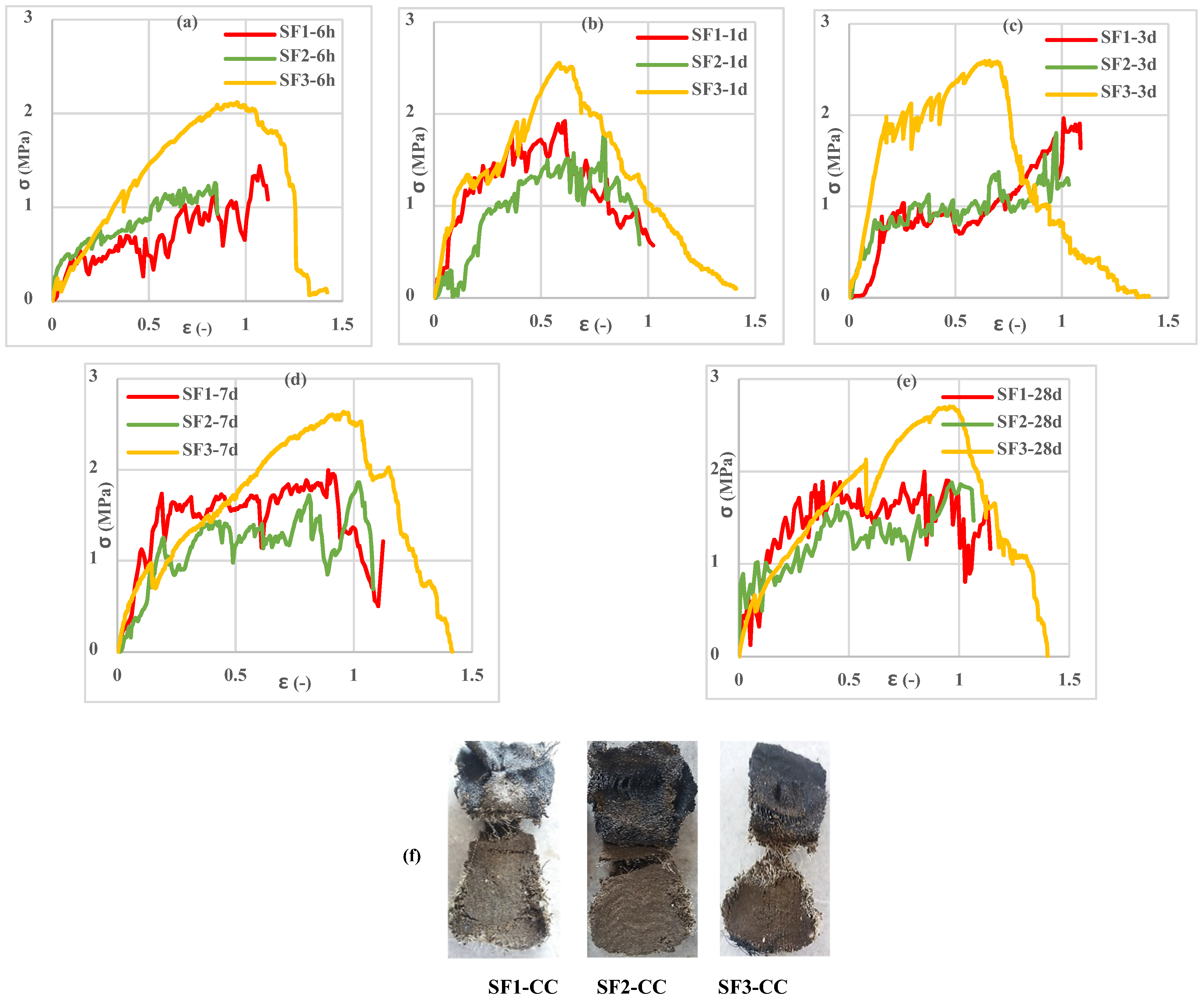
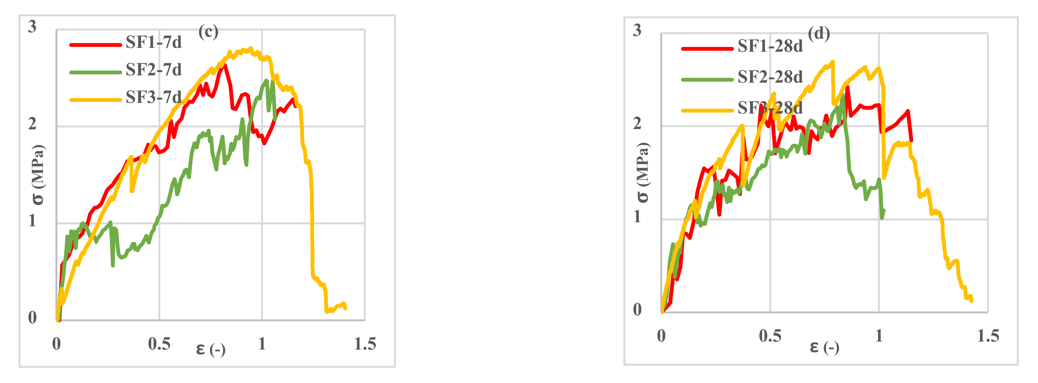
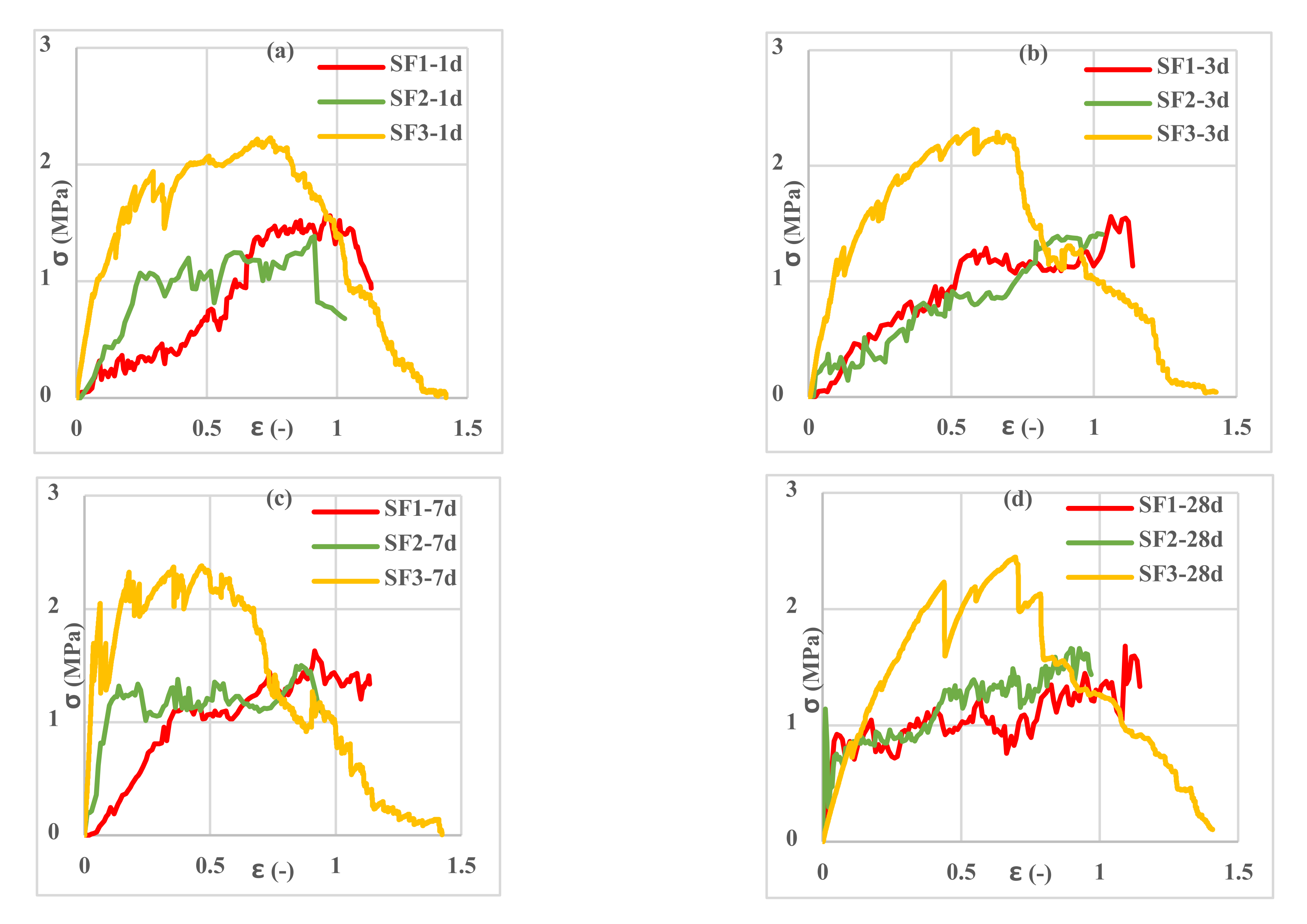
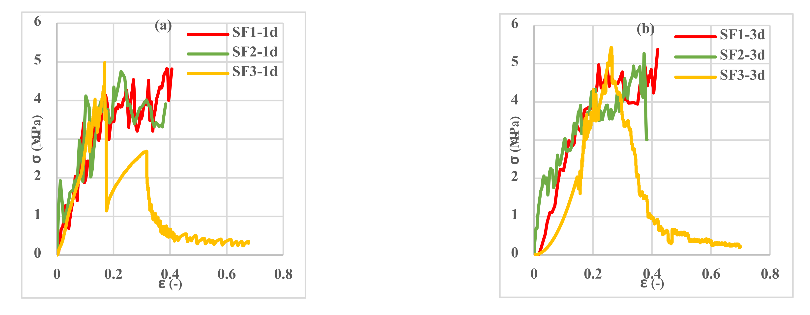
Investigation of the different spacemen results in
Figure 9,
Figure 10,
Figure 11,
Figure 12,
Figure 13 and
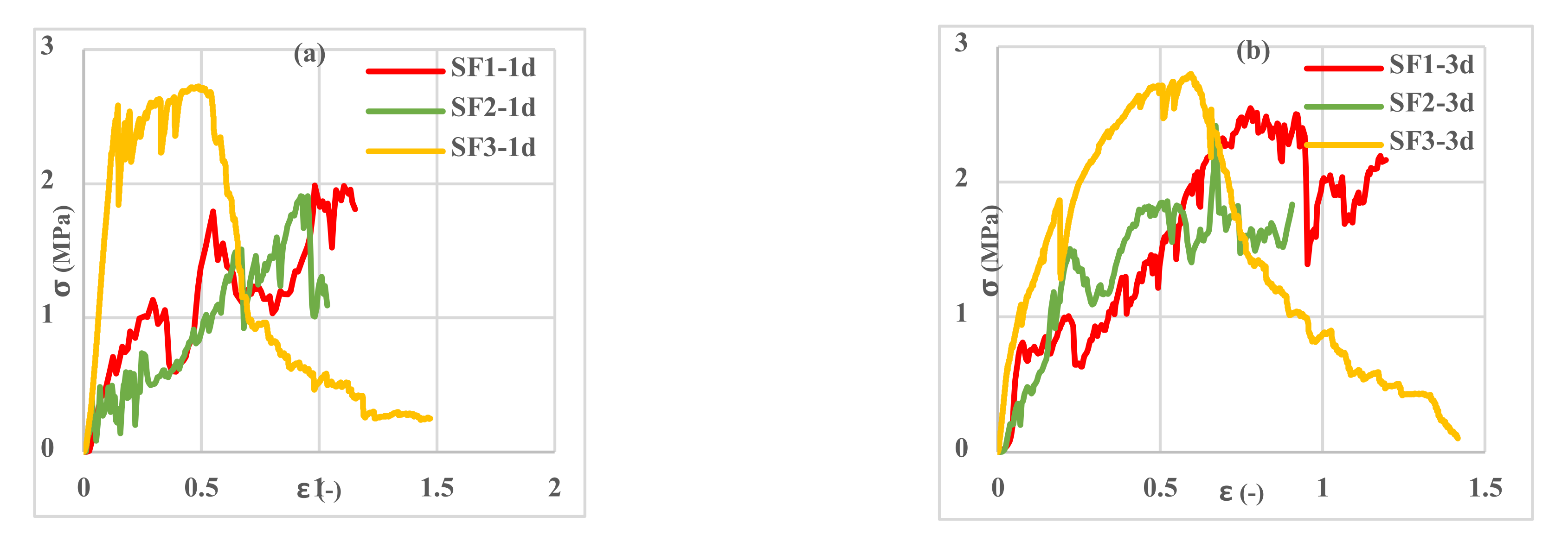
Figure 14 reveals two different fracture types in CC specimens under pure tensile force. First, the mortar initially sustains the applied tensile load up to thorough cracking, and after the mortar breaks, all the applied force will be transferred to the 3D fabric. In this type, only one crack was observed in the middle of the specimens, and in the weft direction, several cracks were observed as a significant fall was observed in the tensile stress–strain graphs. In the second fracture type, the reinforced cementitious composite cracks in both directions, and the specimens’ failure was observed with several cracks. The cracking pattern during the test demonstrated that the tensile force was applied to the stitches of 3D fabric and then it was applied to the yarns. It means that, due to the proper connection between the 3D fabric and the mortar in reinforced cementitious composites, at the same time as the fabric resists the tensile load, the mortar is cracked at different points, and several cracks are observed in the CC. The reinforced cementitious composite is gradually stretched and broken, and in the next steps, the load is then redistributed within the sample and the remaining intact parts are stretched and broken in turn. The fluctuations observed in the different curves of
Figure 9,
Figure 10,
Figure 11,
Figure 12,
Figure 13 and
Figure 14 confirm this multiple crack formation. In addition, As the results in
Table 5, the difference between the maximum amount of ultimate stress and fracture stress in most tensile tests of reinforced cementitious composites was precisely related to the stitch type of the bottom layer of the fabric. The results presented that the tensile stresses of the CCs reinforced with SF2 in the warp direction are less than other samples. Furthermore, it can be concluded that multiple cracks patterns are related to the stitch pattern, the mortar, 3D fabric tensile stress, and their effects on each other in the CC.
The results of the tensile test of the fabrics show that they are similar not only in the warp direction but also in the weft direction. In addition, the tensile behavior of reinforced cementitious composites with these fabrics was similar too. By comparing the mortar and CCs test results with each other, it can be concluded that the mortar had a lower tensile strength than the reinforced cementitious composite (i.e., near the 70% more) due to reinforcement caused by the spacer yarns embedded within the mortar.
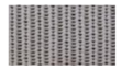
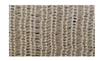
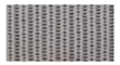
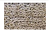
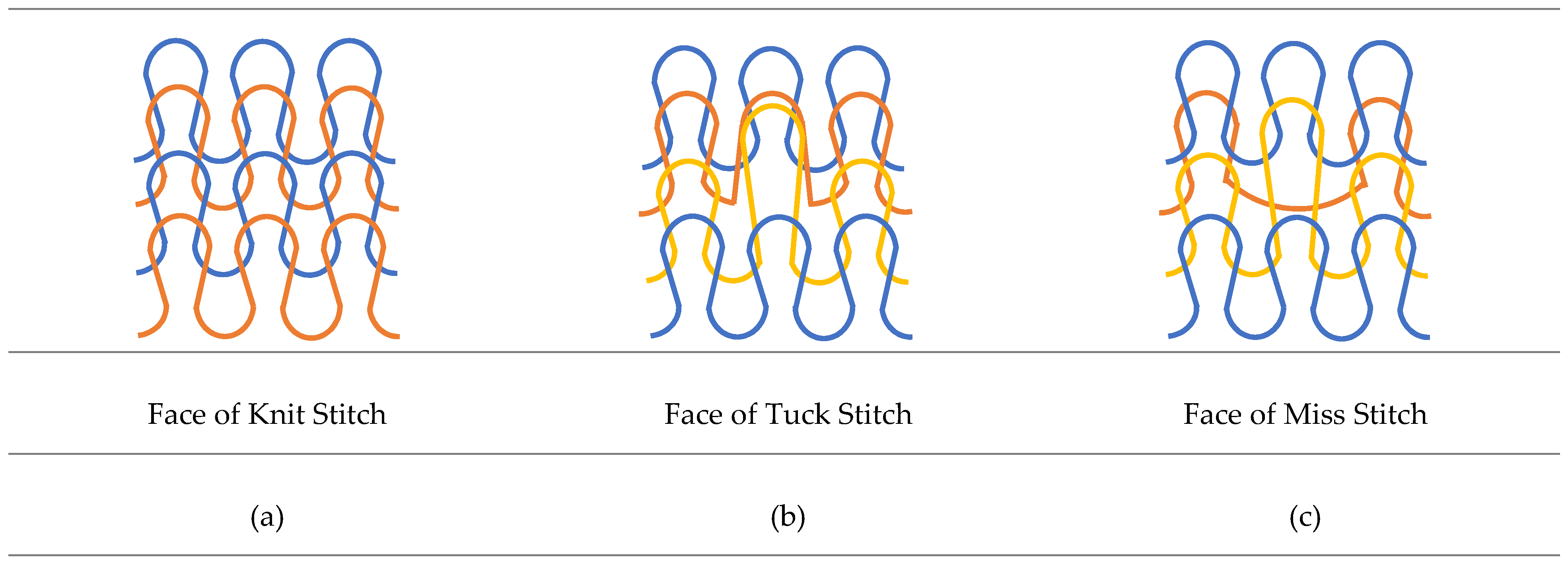
According to the types of spacer fabric presented in
Figure 2, it can be said that there are no floating yarns in the structure of the “tuck stitch” fabric (SF3), but the middle loop is involved with both the next loop and the upper loop. According to the stitch’s structures, this type of tangled involvement of the yarns increased the tensile strength, the maximum of which is found in the “tuck stitch” fabric structure. In addition, in the weft-knitted fabric with a “tuck stitch” structure, the width of the fabric increases and its elasticity decreases [
50], so it can be concluded that the structure of the “tuck stitch” created the maximum tensile strength and maximum elongation. Then, the structure of the “knit stitch” (SF1), due to the homogeneous and uniform distribution of the loops and the homogeneous involvement of the yarns, has the average tensile strength. The “miss stitch” structure (SF2) was due to less involvement and entanglement of the yarns, a floating yarn, and the lowest elasticity [
50], which had the lowest tensile strength. In addition, by comparing the tensile strength and strain until failure, it can be said that the CCs reinforced with SF3 had the highest, and then SF1 and finally SF2 had the lowest tensile strength. Thus, it can be concluded that the choice of the “tuck stitch” structure had the highest, then “knit stitch” and finally “miss stitch” had the lowest tensile strength.
By comparing the curves in
Figure 9,
Figure 10,
Figure 11,
Figure 12,
Figure 13 and
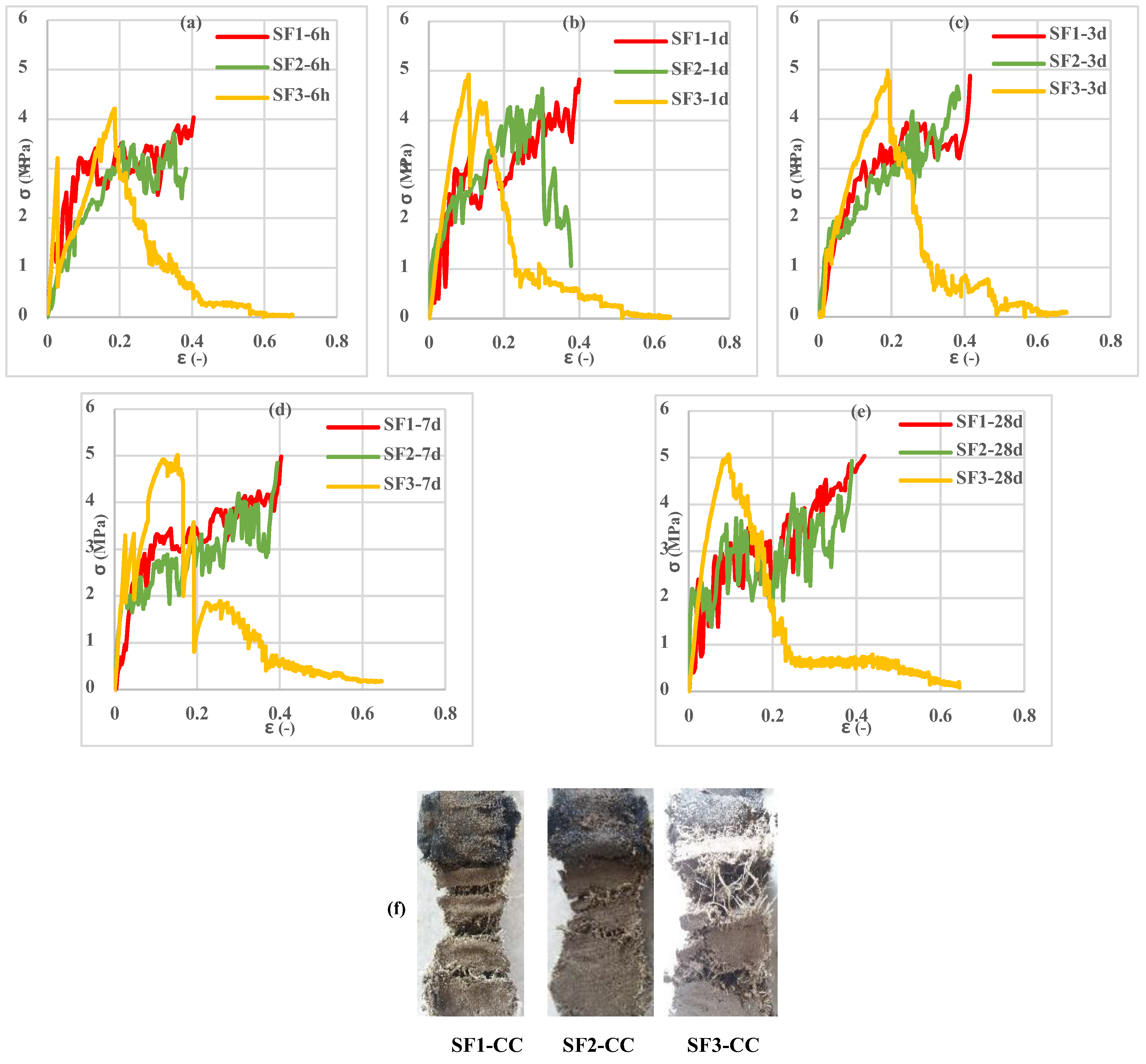
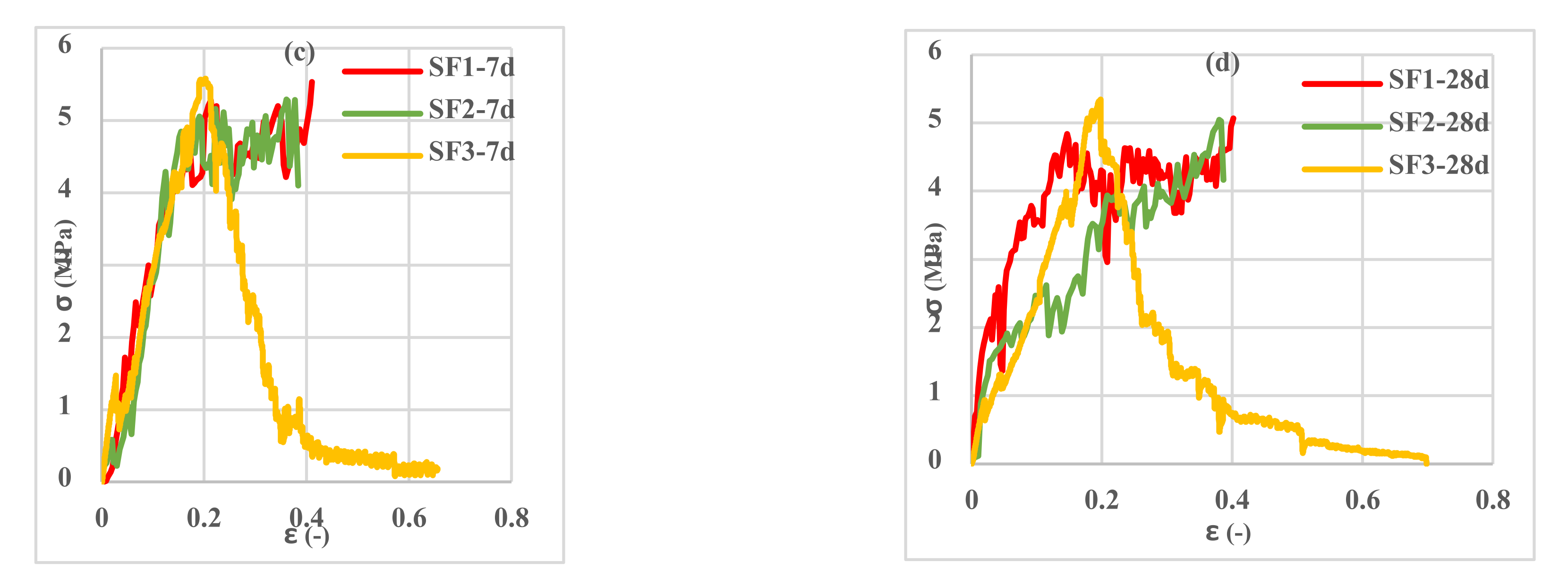
Figure 14, it can be concluded that the maximum tensile stress was observed at 23 °C, then at 7 °C, and 50 °C had the lowest tensile stress. This behavior is due to chemical changes in the structure of the CAC mortar and the inversion of the unstable phase to the stable one.
In all three temperature conditions, it was observed that tensile stress was increased when increasing the curing age of the samples. However, at 23 °C, the tensile stress decreased at 28 days probably due to the inversion phenomenon. In all diagrams, the tensile behavior of CCs reinforced with fabrics SF1 and SF2 has almost the same performance.
According to the results obtained from the effect of fabric tensile direction (warp or weft) on the tensile stress of the different CCs, the highest tensile strain was observed in the CC tensile in the warp direction due to greater freedom of movement in monofilament yarns.
According to the results presented in
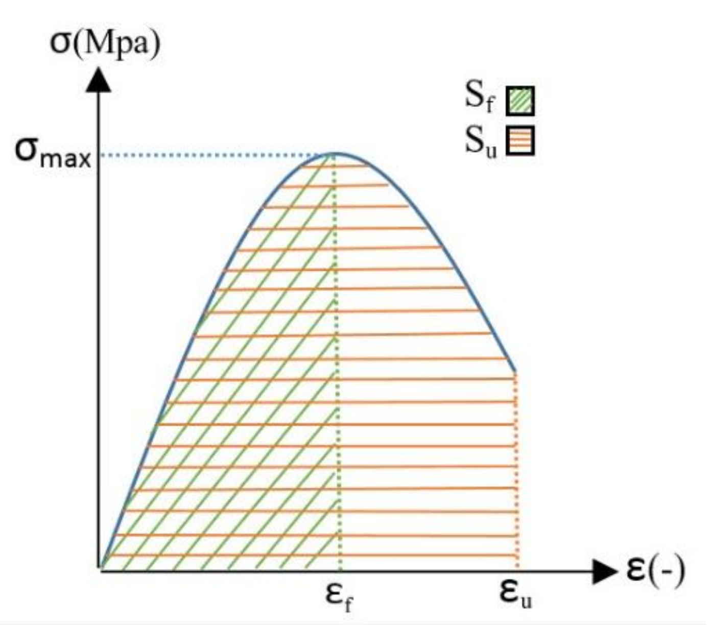
Figure 6, SF1 and SF2 fabrics bore lower stress and strain than the SF3 fabric, so when SF1 and SF2 fabrics were used to reinforce the CC, the related specimens failed during the tensile test. In CCs reinforced with SF3, because the bottom layer of fabric and the middle spacer yarns do not tear simultaneously, the stress–strain curve gradually decreases and continues to a minimum at the end of the test. Therefore, the endpoint of the test in the tensile stress–strain curve of SF1 and SF2-reinforced cementitious composites appears in the region with higher stress and lower strain than for SF3-reinforced cementitious composites. According to
Figure 15, the strain at the maximum stress is referred to as the “fracture” strain (
εf). The strain at the end of the test is denoted as “ultimate” strain (
εu), and the ratio of fracture strain to ultimate strain is denoted as cross-sectional strain capacity. The above-defined quantities are reported in
Table 6.
The force–displacement curve integral was used to calculate the fracture energy of reinforced cementitious composites. The absorbed energy per unit area was calculated by integrating the area below the curve [
51,
52].
Figure 15 shows a schematic of a stress–strain curve, with indication of the fracture strain, the ultimate strain, and the subtended area. The energy absorbed per unit area in tensile tests of reinforced cementitious composites at the different temperature values and ages are reported in
Table 6. The samples examined in
Table 6 are denoted with an abbreviation code in the form of “fabric type—fabric direction—storage age—storage temperature”. For example, the abbreviation code “7 °C-6 h-w SF1” indicates a CC reinforced with SF1 fabric in the direction of width and age of 6 h, stored at 7 °C.
According to
Table 6, it was observed that the CC reinforced with SF3 had the highest final strain (ε
u), then SF1 and finally SF2 had the lowest final strain regardless of the ages, curing temperature values, and different directions of the fabric. These results are also consistent with the fabric tension results (presented in
Figure 6). The table above also examines the cross-sectional strain capacity (ε
f/ε
u) in different fabric directions. The cross-sectional strain capacity in the weft direction (for all ages and temperature values) for CCs reinforced with different fabrics is as follows: SF1 = 1, 0.59 < SF2 < 1 and 0.11 < SF3 < 0.37. It can be mentioned that the cross-sectional strain capacity was the highest for SF1 fabric-reinforced cementitious composites, followed by SF2 and finally SF3. On the other hand, the cross-sectional strain capacity in the warp direction (for all ages and temperature values) is highest for SF2 fabric-reinforced cementitious composites (0.7 < ε
f/ε
u < 0.9), followed by SF1 (0.5 < ε
f/ε
u < 0.9), and SF3 (0.3 < ε
f/ε
u < 0.6) was the lowest value. The results related to the absorbed energy up to the fracture strain point (maximum tensile stress) are presented in
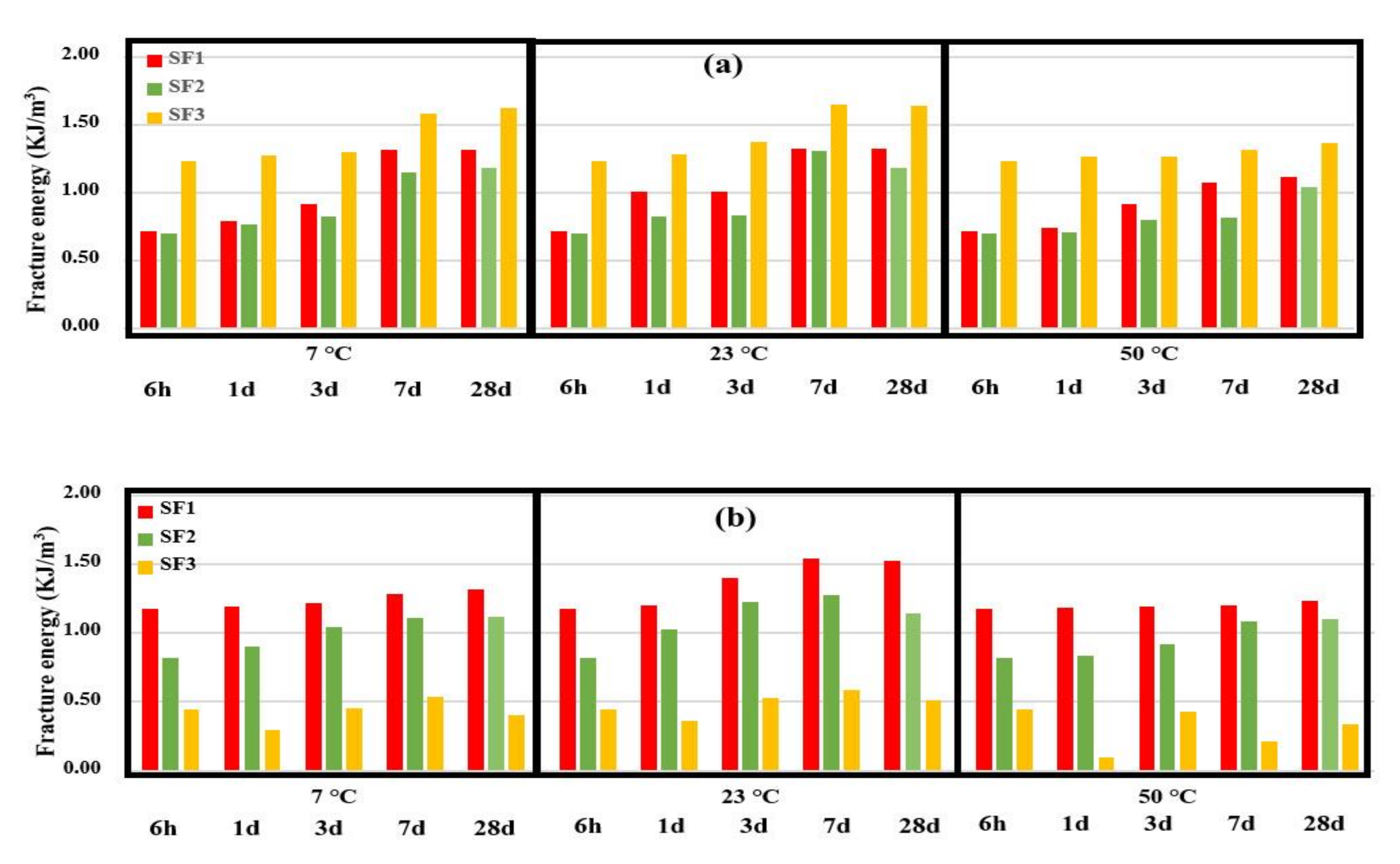
Figure 16.
According to
Figure 16, it can be seen that with increasing the curing age of 3D fabric-reinforced cementitious composites, the absorbed energy increased. At the age of 28 days and at 23 °C, due to the inversion phenomenon, tensile stress decreased and absorbed energy reduced. The increasing trend of energy absorption in the different CCs is due to the hardening of the cement phase and to the higher interaction of the cementitious mortar with the fabric. All CCs had this trend, but SF3-reinforced cementitious composites’ absorbed energy did not have a specific trend in the weft direction. The highest fracture energy was determined with the samples cured at 23 °C, then 7 °C, while the samples cured at 50 °C that had the lowest level fracture energy. In 3D fabric-reinforced cementitious composites in the warp direction, SF3 had the highest absorbed energy, and SF1 and SF2 had the lowest absorbed energy. These results are in line with the results of the values of tensile strength. The tensile test of reinforced cementitious composite in the weft direction showed that SF1 had the highest absorbed energy, and SF2 and SF3 had the lowest absorbed energy, which contrasts the results of CCs in the warp direction.
4. Conclusions
This research aims to study simultaneous effects of temperature and curing age in CAC mortar and the three different hole patterns (stitch structures) of the bottom layer of the 3D fabrics in warp and weft directions on the tensile properties of the composite. Tensile tests have been performed to obtain warp and weft tensile stress–strain curves, and the fracture energy of the CC has been presented. To investigate and analyze the tensile behavior of reinforced cementitious composite, each of its components, including yarns, 3D fabrics, cement phase, and finally, reinforced composites, were subjected to tensile tests, and the behavior of each was examined separately. Three 3D fabrics with different stitch structures use in the bottom layer, and their effect on the tensile behavior of the CC was investigated. The stress-strain curves of the CCs in different directions (warp and weft), ages, and curing conditions were obtained, and the experimental results were analyzed. The results are presented as follows:
Three types of 3D fabric (SF1-SF2-SF3) with three different types of loop textures in the bottom layer of the fabric in terms of length and width were stretched, and the SF3 fabric had the highest tensile capacity and ductility compared to the other 3D fabrics. The SF1 had the least amount of stress and strain.
By examining the amount of stress and strain in fabrics in both warp and weft directions, it was observed that reinforced CCs had higher tensile strength and lower strain in the weft direction than in the warp direction. This trend was observed in all three types of fabrics.
Reinforced cementitious composites with 3D fabrics were studied on the basis of two features: the maximum tensile stress and the maximum absorbed energy. Examination of the ultimate tensile stress of reinforced cementitious CCs showed that the composites reinforced with SF3 have the highest tensile stress; then, CC reinforced with SF1 and reinforced with SF2 fabric. This trend was similar in terms of warp and weft direction. By examining the absorbed energy of reinforced cementitious composites, it was observed that the CCs reinforced with SF3 had the highest absorbed energy in the warp direction. Then SF1 and SF2 had the lowest absorbed energy. CCs reinforced with SF1 had the highest absorbed energy in the weft direction, and then SF2 while SF3 had the lowest absorbed energy.
In this paper, the cement phase mixing design was considered fixed, and the method of achieving this mixing design is presented in a separate article. Different angles of spacer yarns in 3D fabric, yarn material, 3D fabric thickness, etc., could be influential factors that have not been studied in this article, and each can be examined separately in several articles. In this paper, reinforced cement composites were only tested for tensile strength. The results of composite bending tests along with their modeling and optimization by ABAQUS software will be present in future papers.


 ,
, 


