
Enhanced Defect Detection in Carbon Fiber Reinforced Polymer Composites via Generative Kernel Principal Component Thermography


Abstract
:
1. Introduction
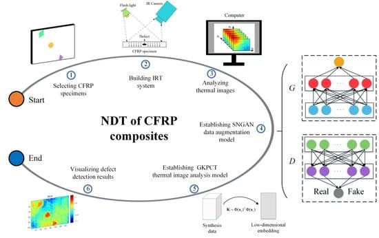
2. Methodology
2.1. KPCT–Nonlinear Thermographic Data Analysis Approach
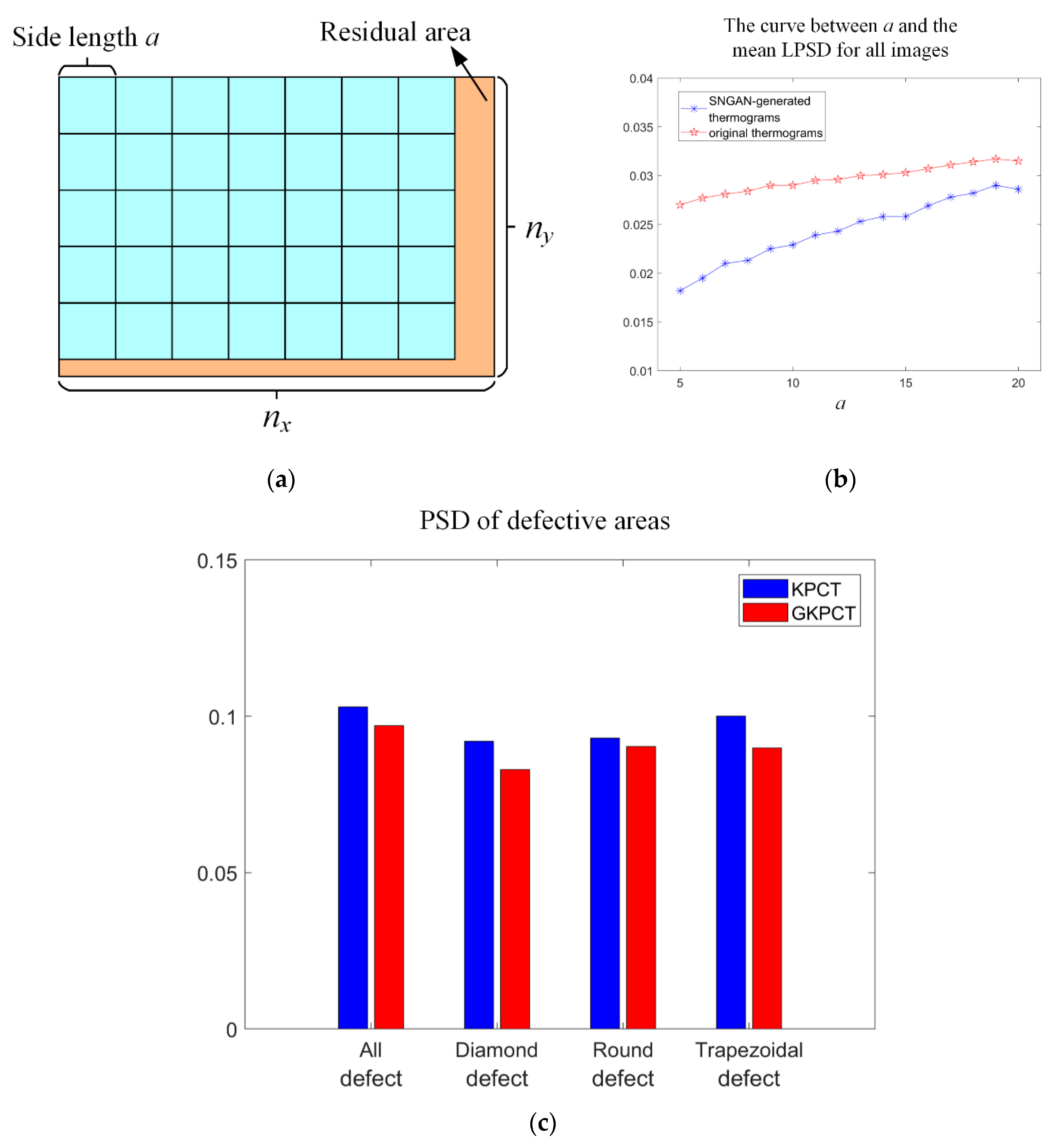
2.2. GKPCT-KPCT Approach Based on Image Augmentation
3. Experiments
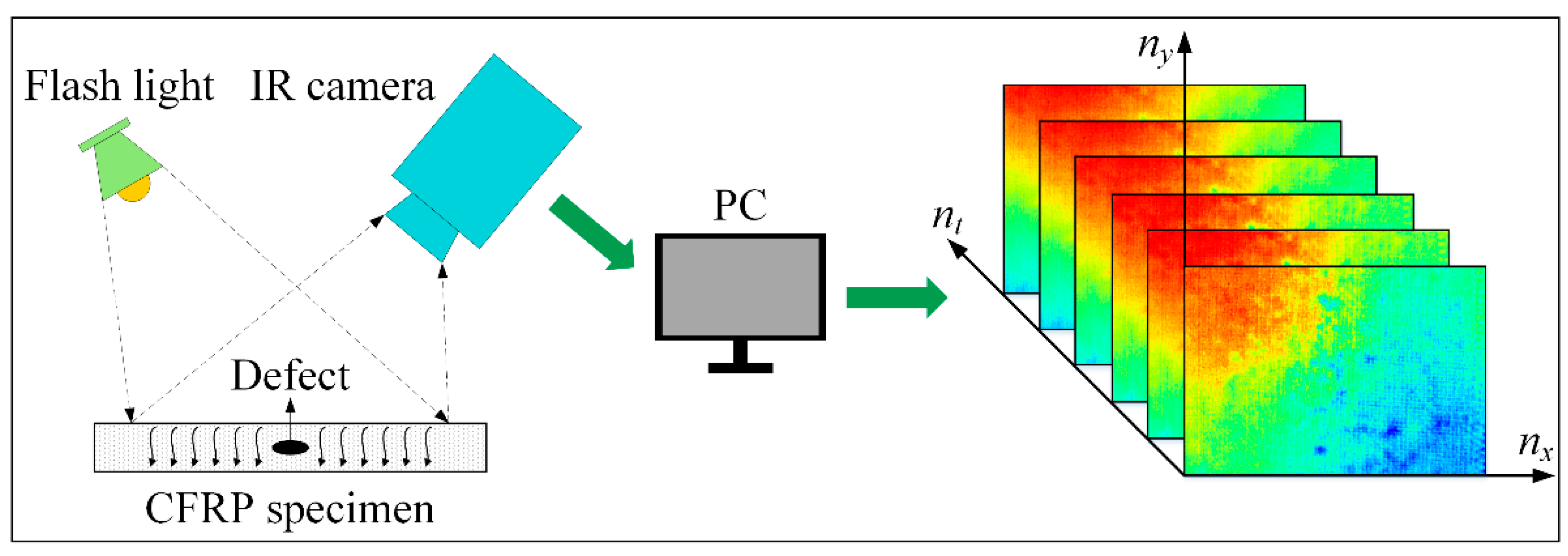
3.1. Manufacturing and Data Acquisition of CFRP Specimen 1
3.2. Manufacturing and Data Acquisition of CFRP Specimen 2
4. Results and Discussion
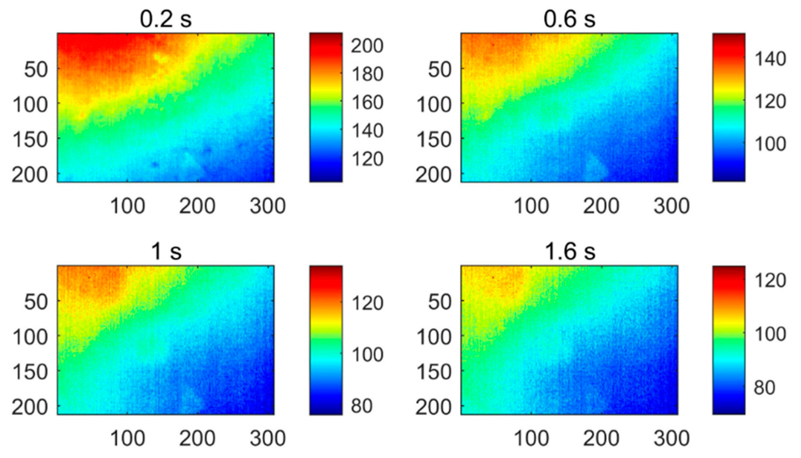
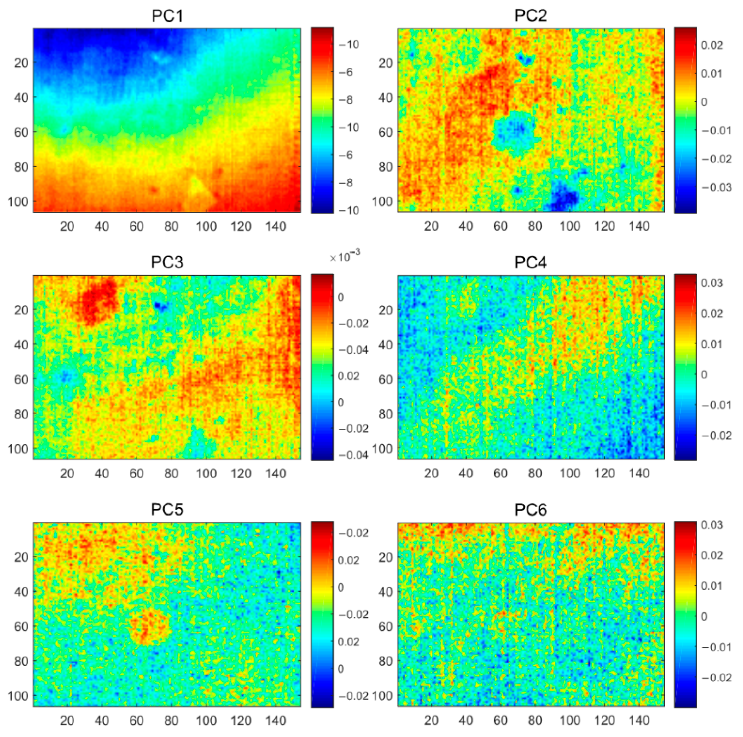
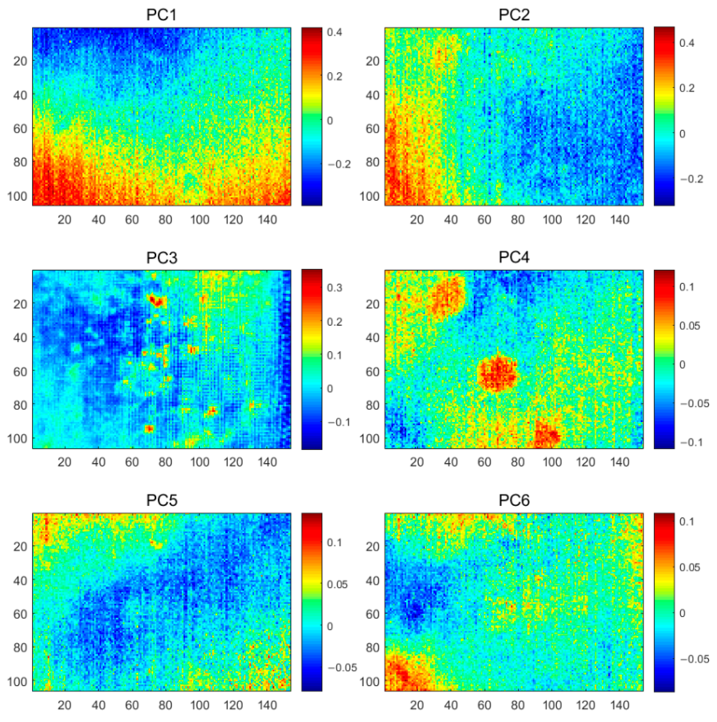
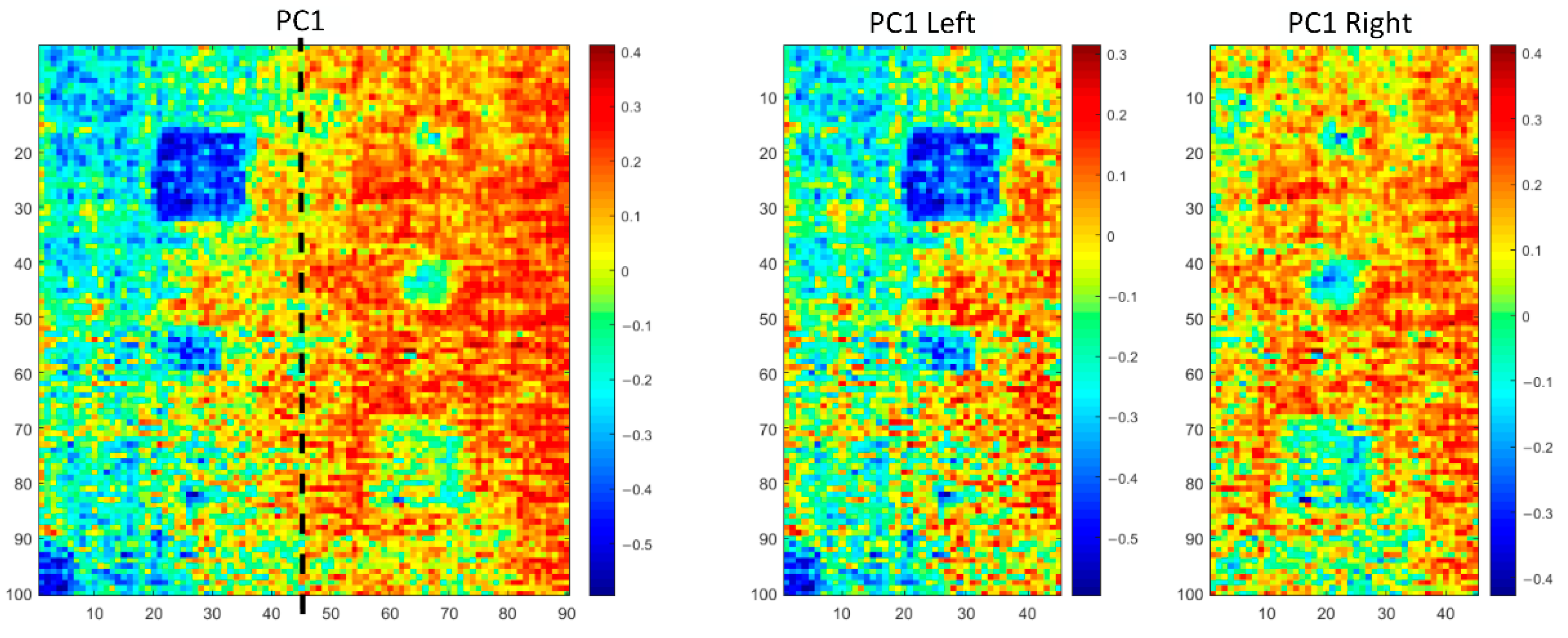
4.1. Thermal Image Data Analysis of Specimen 1
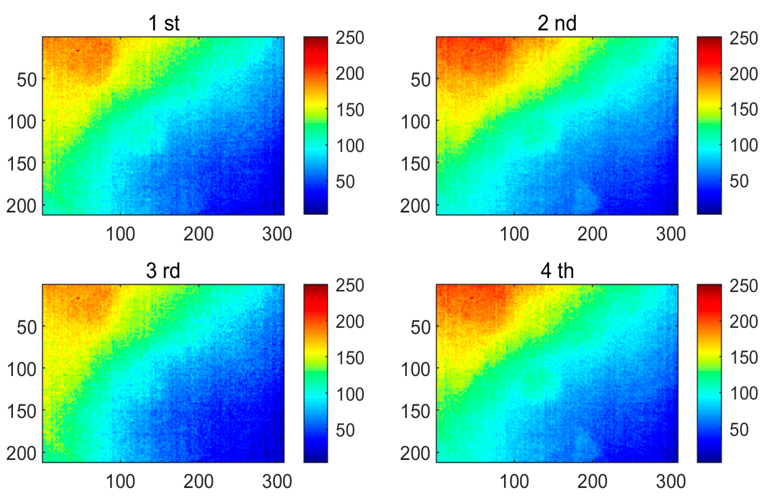
4.2. Performance Analysis of GKPCT Method on Specimen 1
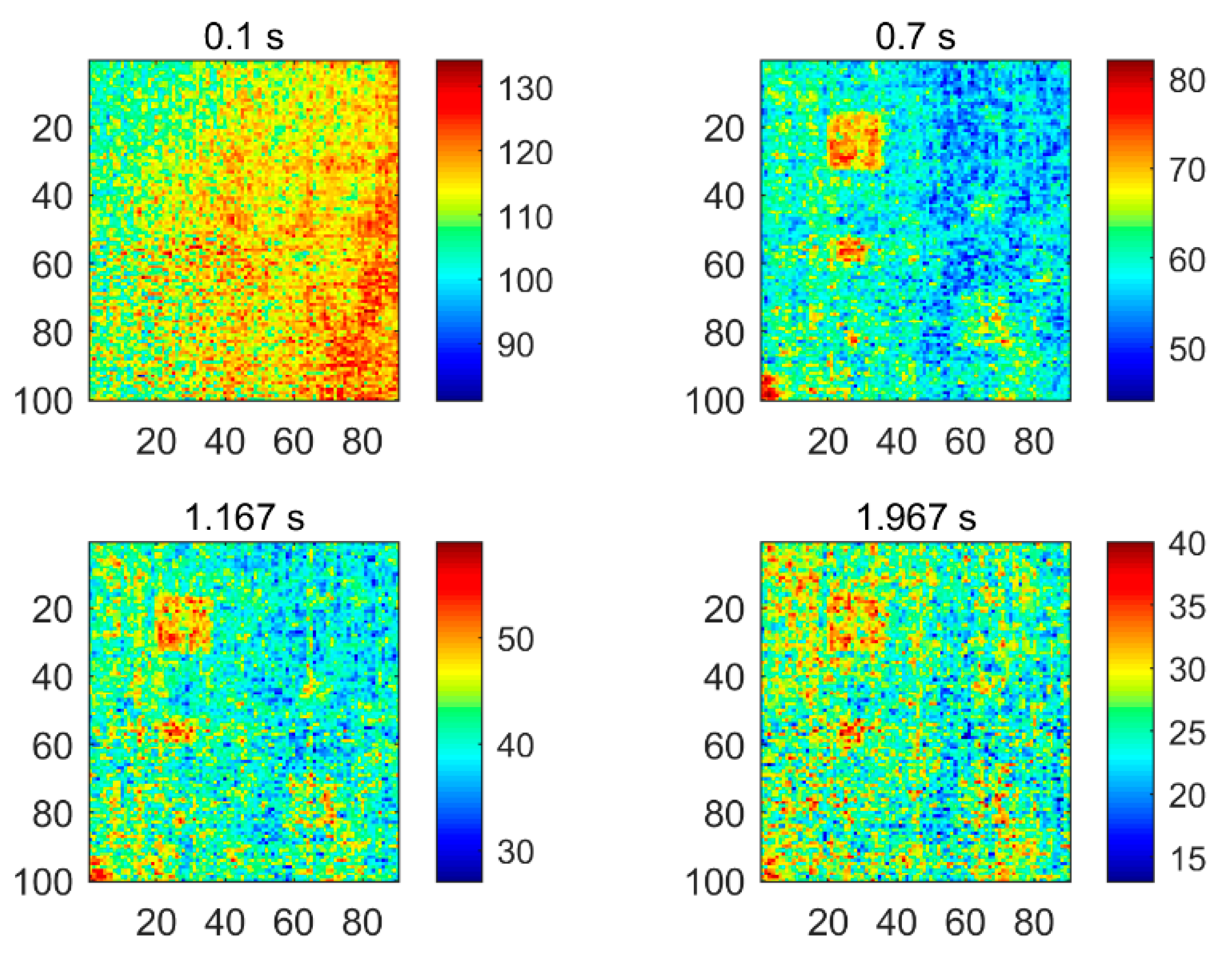
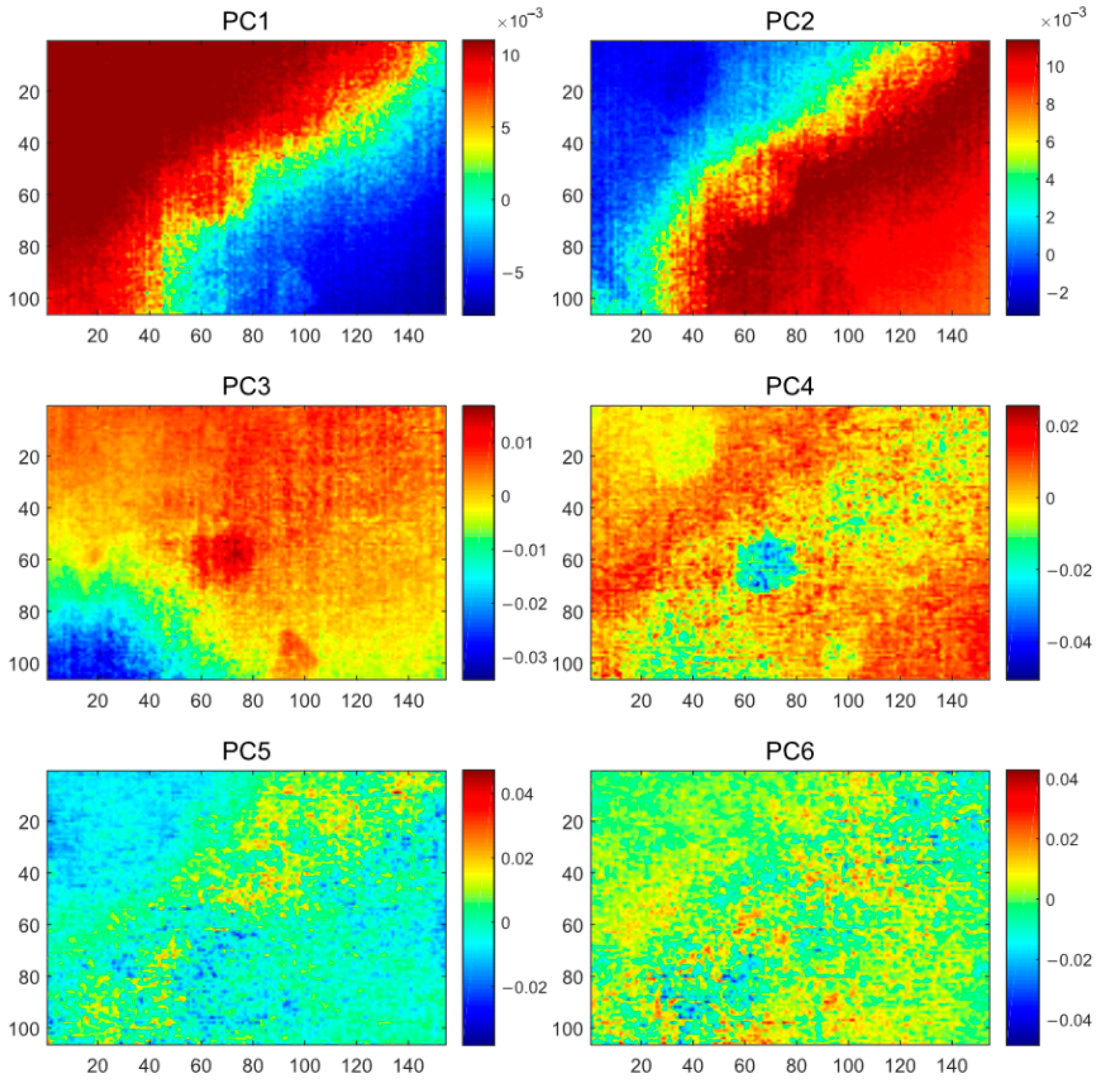
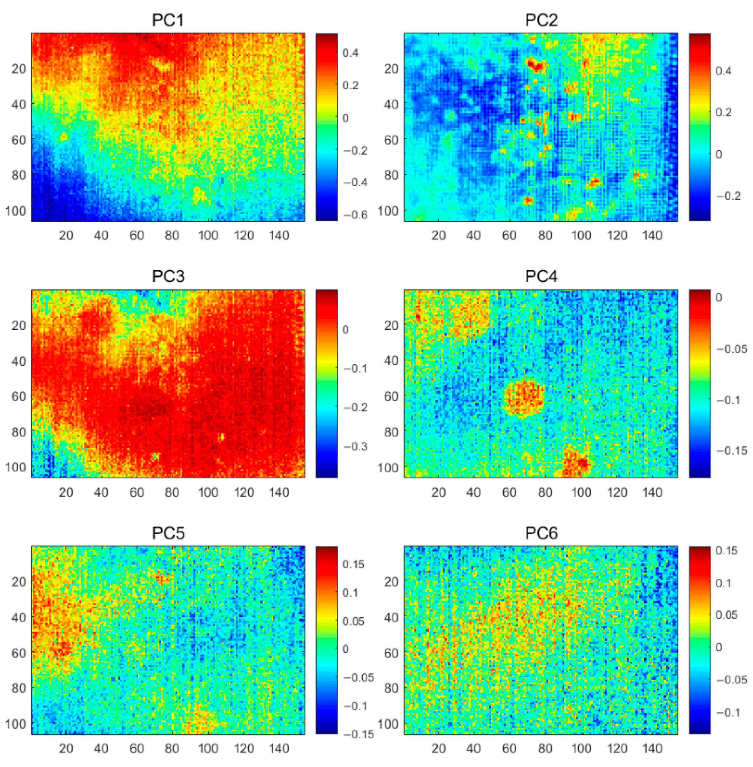
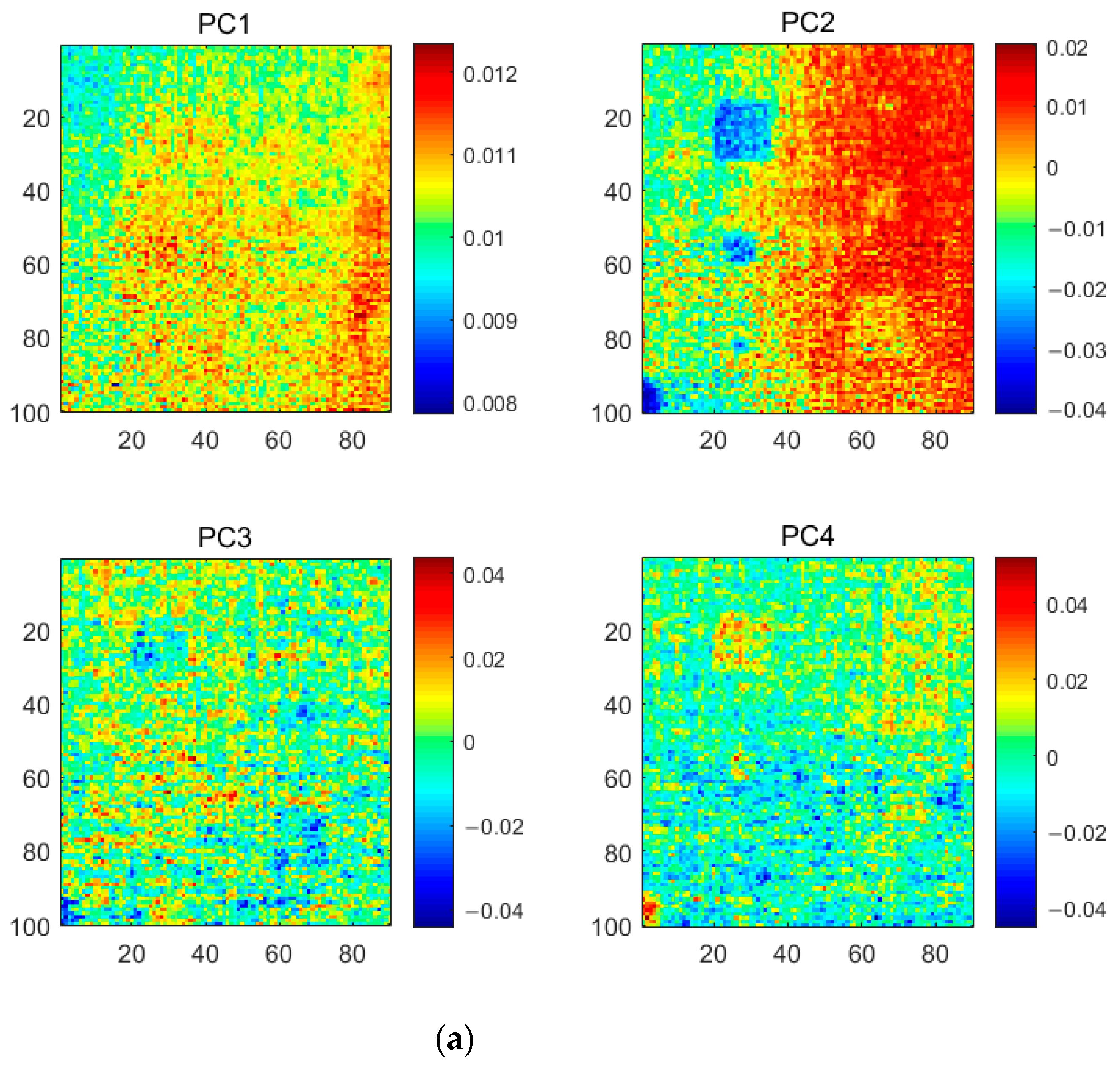
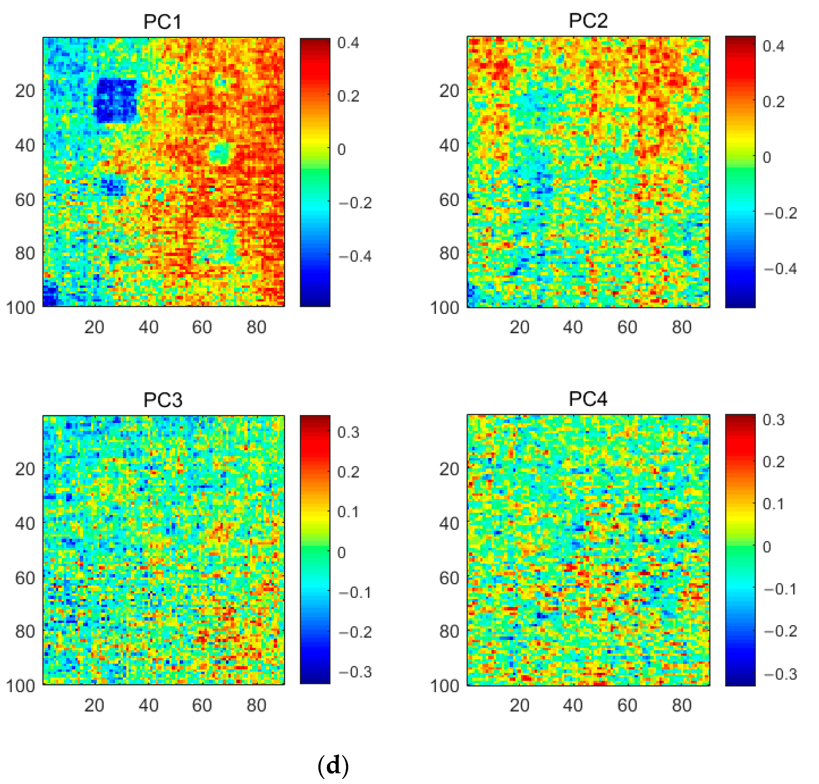
4.3. Thermal Image Data Analysis of Specimen 2
5. Conclusions
Author Contributions
Funding
Institutional Review Board Statement
Informed Consent Statement
Data Availability Statement
Conflicts of Interest
References
- Ibarra-Castanedo, C.; Tarpani, J.R.; Maldague, X.P.V. Nondestructive testing with thermography. Eur. J. Phys. 2013, 34, S91–S109. [Google Scholar] [CrossRef]
- Amer, S.; Al Zarkani, H.; Sfarra, S.; Omar, M. Infrared thermography approach for pipelines and cylindrical based geometries. Polym. 2020, 12, 1616. [Google Scholar] [CrossRef]
- Sun, S.; Han, Z.; Fu, H.; Jin, H.; Dhupia, J.S.; Wang, Y. Defect characteristics and online detection techniques during manufacturing of FRPs using automated fiber placement: A review. Polymer 2020, 12, 1337. [Google Scholar] [CrossRef]
- Titman, D. Applications of thermography in non-destructive testing of structures. NDT E Int. 2001, 34, 149–154. [Google Scholar] [CrossRef]
- Ibarra-Castanedo, C.; González, D.; Klein, M.; Pilla, M.; Vallerand, S.; Maldague, X. Infrared image processing and data analysis. Infrared Phys. Technol. 2004, 46, 75–83. [Google Scholar] [CrossRef]
- Yan, Z.; Chen, C.-Y.; Luo, L.; Yao, Y. Stable principal component pursuit-based thermographic data analysis for defect detection in polymer composites. J. Process. Control. 2017, 49, 36–44. [Google Scholar] [CrossRef]
- LeCun, Y.; Bengio, Y.; Hinton, G. Deep learning. Nature 2015, 521, 436–444. [Google Scholar] [CrossRef] [PubMed]
- Xuan, Q.; Chen, Z.; Liu, Y.; Huang, H.; Bao, G.; Zhang, D. Multiview generative adversarial network and its application in pearl classification. IEEE Trans. Ind. Electron. 2019, 66, 8244–8252. [Google Scholar] [CrossRef]
- Deng, H.; Yang, K.; Liu, Y.; Zhang, S.; Yao, Y. Actively exploring informative data for smart modeling of industrial multiphase flow processes. IEEE Trans. Ind. Inform. 2021, 1. [Google Scholar] [CrossRef]
- Rajic, N. Principal component thermography for flaw contrast enhancement and flaw depth characterisation in composite structures. Compos. Struct. 2002, 58, 521–528. [Google Scholar] [CrossRef]
- Wu, J.-Y.; Sfarra, S.; Yao, Y. Sparse principal component thermography for subsurface defect detection in composite products. IEEE Trans. Ind. Inform. 2018, 14, 5594–5600. [Google Scholar] [CrossRef]
- Yousefi, B.; Sfarra, S.; Castanedo, C.I.; Maldague, X.P. Comparative analysis on thermal non-destructive testing imagery applying candid covariance-free incremental principal component thermography (CCIPCT). Infrared Phys. Technol. 2017, 85, 163–169. [Google Scholar] [CrossRef]
- Liu, K.; Li, Y.; Yang, J.; Liu, Y.; Yao, Y. Generative principal component thermography for enhanced defect detection and analysis. IEEE Trans. Instrum. Meas. 2020, 69, 8261–8269. [Google Scholar] [CrossRef]
- Balageas, D.L.; Roche, J.-M.; Leroy, F.-H.; Liu, W.-M.; Gorbach, A.M. The thermographic signal reconstruction method: A powerful tool for the enhancement of transient thermographic images. Biocybern. Biomed. Eng. 2015, 35, 1–9. [Google Scholar] [CrossRef] [Green Version]
- Zheng, K.; Chang, Y.-S.; Yao, Y. Defect detection in CFRP structures using pulsed thermographic data enhanced by penalized least squares methods. Compos. Part B Eng. 2015, 79, 351–358. [Google Scholar] [CrossRef]
- Maldague, X.; Galmiche, F.; Ziadi, A. Advances in pulsed phase thermography. Infrared Phys. Technol. 2002, 43, 175–181. [Google Scholar] [CrossRef] [Green Version]
- Liu, Y.; Wu, J.Y.; Liu, K.; Wen, H.L.; Yao, Y.; Sfarra, S.; Zhao, C. Independent component thermography for non-destructive assessment of defects in polymer composites. Meas. Sci. Technol. 2019, 30, 044006. [Google Scholar] [CrossRef]
- Zhang, X.; He, Y.; Chady, T.; Tian, G.Y.; Gao, J.; Wang, H.; Chen, S. CFRP impact damage inspection based on manifold learning using ultrasonic induced thermography. IEEE Trans. Ind. Inform. 2018, 15, 2648–2659. [Google Scholar] [CrossRef]
- Liu, Y.; Liu, K.; Yang, J.; Yao, Y. Spatial-neighborhood manifold learning for nondestructive testing of defects in polymer composites. IEEE Trans. Ind. Inform. 2020, 16, 4639–4649. [Google Scholar] [CrossRef]
- Liu, Y.; Liu, K.; Gao, Z.; Yao, Y.; Sfarra, S.; Zhang, H.; Maldague, X.P. Non-destructive defect evaluation of polymer composites via thermographic data analysis: A manifold learning method. Infrared Phys. Technol. 2019, 97, 300–308. [Google Scholar] [CrossRef]
- Wu, H.; Zheng, K.; Sfarra, S.; Liu, Y.; Yao, Y. Multiview learning for subsurface defect detection in composite products: A challenge on thermographic data analysis. IEEE Trans. Ind. Inform. 2020, 16, 5996–6003. [Google Scholar] [CrossRef]
- Xu, C.; Xie, J.; Wu, C.; Gao, L.; Chen, G.; Song, G. Enhancing the visibility of delamination during pulsed thermography of carbon fiber-reinforced plates using a stacked autoencoder. Sensors 2018, 18, 2809. [Google Scholar] [CrossRef]
- Ramesh, V. A review on application of deep learning in thermography. Int. J. Eng. Manage. Res. 2017, 7, 489–493. [Google Scholar]
- Manduchi, G.; Marinetti, S.; Bison, P.; Grinzato, E. Application of neural network computing to thermal non-destructive evaluation. Neural Comput. Appl. 1997, 6, 148–157. [Google Scholar] [CrossRef]
- Bang, H.-T.; Park, S.; Jeon, H. Defect identification in composite materials via thermography and deep learning techniques. Compos. Struct. 2020, 246, 112405. [Google Scholar] [CrossRef]
- Kulis, B. Metric Learning: A Survey. Found. Trends Mach. Learn. 2013, 5, 287–364. [Google Scholar] [CrossRef]
- Miyato, T.; Kataoka, T.; Koyama, M.; Yoshida, Y. Spectral normalization for generative adversarial networks. arXiv 2018, arXiv:1802.05957. [Google Scholar]
- Kim, K.I.; Jung, K.; Kim, H.J. Face recognition using kernel principal component analysis. IEEE Signal Process. Lett. 2002, 9, 40–42. [Google Scholar] [CrossRef] [Green Version]
- Creswell, A.; White, T.; Dumoulin, V.; Arulkumaran, K.; Sengupta, B.; Bharath, A.A. Generative adversarial networks: An overview. IEEE Signal Process. Mag. 2018, 35, 53–65. [Google Scholar] [CrossRef] [Green Version]
- Guei, A.-C.; Akhloufi, M. Deep learning enhancement of infrared face images using generative adversarial networks. Appl. Opt. 2018, 57, D98–D107. [Google Scholar] [CrossRef]
- Wei, B.-J.; Chang, Y.-S.; Yao, Y.; Fang, J. Online estimation and monitoring of local permeability in resin transfer molding. Polym. Compos. 2016, 37, 1249–1258. [Google Scholar] [CrossRef]
- Ibarra-Castanedo, C.; Piau, J.-M.; Guilbert, S.; Avdelidis, N.P.; Genest, M.; Bendada, A.; Maldague, X.P.V. Comparative study of active thermography techniques for the nondestructive evaluation of honeycomb structures. Res. Nondestruct. Eval. 2009, 20, 1–31. [Google Scholar] [CrossRef]
- Meola, C.; Carlomagno, G.M. Recent advances in the use of infrared thermography. Meas. Sci. Technol. 2004, 15, R27–R58. [Google Scholar] [CrossRef]
- Shrestha, R.; Kim, W. Non-destructive testing and evaluation of materials using active thermography and enhancement of signal to noise ratio through data fusion. Infrared Phys. Technol. 2018, 94, 78–84. [Google Scholar] [CrossRef]
- Maaten, L.V.D.; Hinton, G. Visualizing data using t-sne. J. Mach. Learn. Res. 2008, 9, 2579–2605. [Google Scholar]


| SNR | ||||
|---|---|---|---|---|
| Diamond Defect | Circular Defect | Trapezoidal Defect | All Defects | |
| Original images | 1.50 | 0.48 | 1.14 | 0.72 |
| PCT [11] | 1.97 | 2.04 | 3.35 | 1.67 |
| GPCT [13] | 1.74 | 2.56 | 2.25 | 1.35 |
| KPCT | 1.85 | 2.22 | 2.33 | 2.00 |
| GKPCT | 1.91 | 2.61 | 3.64 | 2.25 |
| SNR | |||||||
|---|---|---|---|---|---|---|---|
| Defect A1 | Defect B1 | Defect C1 | Defect A2 | Defect B2 | Defect C2 | All Defects | |
| Original images | 0.83 | 0.93 | 1.09 | 0.84 | 0.90 | 1.06 | 0.17 |
| PCT [11] | 1.67 | 1.52 | 1.33 | 1.25 | 1.27 | 1.14 | 0.67 |
| GPCT [13] | 2.01 | 1.82 | 1.57 | 1.32 | 1.45 | 1.22 | 1.16 |
| KPCT | 2.17 | 1.86 | 1.46 | 1.40 | 1.53 | 1.19 | 1.22 |
| GKPCT | 1.94 | 1.78 | 1.54 | 1.43 | 1.56 | 1.21 | 1.27 |
| SNR | |||||||
|---|---|---|---|---|---|---|---|
| Defect A1 | Defect B1 | Defect C1 | Defect A2 | Defect B2 | Defect C2 | All Defects | |
| PCT [11] | 1.83 | 1.74 | 1.49 | 1.18 | 1.02 | 0.96 | 0.67 |
| GPCT [13] | 2.08 | 1.92 | 1.68 | 1.24 | 1.29 | 1.07 | 1.16 |
| KPCT | 2.25 | 1.99 | 1.57 | 1.35 | 1.47 | 1.13 | 1.22 |
| GKPCT | 2.54 | 2.18 | 1.71 | 1.46 | 1.60 | 1.28 | 1.27 |
| LPSD | |||||||
|---|---|---|---|---|---|---|---|
| Defect A1 | Defect B1 | Defect C1 | Defect A2 | Defect B2 | Defect C2 | All Defects | |
| PCT [11] | 0.0112 | 0.0131 | 0.0111 | 0.0122 | 0.0123 | 0.0123 | 0.0114 |
| KPCT | 0.1390 | 0.1716 | 0.1422 | 0.1011 | 0.0949 | 0.0891 | 0.1772 |
| GKPCT | 0.1561 | 0.2081 | 0.1731 | 0.1279 | 0.1324 | 0.1035 | 0.1973 |
Publisher’s Note: MDPI stays neutral with regard to jurisdictional claims in published maps and institutional affiliations. |
© 2021 by the authors. Licensee MDPI, Basel, Switzerland. This article is an open access article distributed under the terms and conditions of the Creative Commons Attribution (CC BY) license (http://creativecommons.org/licenses/by/4.0/).
Share and Cite
Liu, K.; Ma, Z.; Liu, Y.; Yang, J.; Yao, Y. Enhanced Defect Detection in Carbon Fiber Reinforced Polymer Composites via Generative Kernel Principal Component Thermography. Polymers 2021, 13, 825. https://doi.org/10.3390/polym13050825
Liu K, Ma Z, Liu Y, Yang J, Yao Y. Enhanced Defect Detection in Carbon Fiber Reinforced Polymer Composites via Generative Kernel Principal Component Thermography. Polymers. 2021; 13(5):825. https://doi.org/10.3390/polym13050825
Chicago/Turabian StyleLiu, Kaixin, Zhengyang Ma, Yi Liu, Jianguo Yang, and Yuan Yao. 2021. "Enhanced Defect Detection in Carbon Fiber Reinforced Polymer Composites via Generative Kernel Principal Component Thermography" Polymers 13, no. 5: 825. https://doi.org/10.3390/polym13050825