
Polymer Hybrid Nanocomposites Based on Homo and Copolymer Xlpe Containing Mineral Nanofillers with Improved Functional Properties Intended for Insulation of Submarine Cables

 , , , ,
  and
and
Abstract
:1. Introduction
2. Sample Preparation and Characterization Techniques
2.1. Materials
2.2. Sample Preparation
2.3. Characterization Techniques
3. Results and Discussion
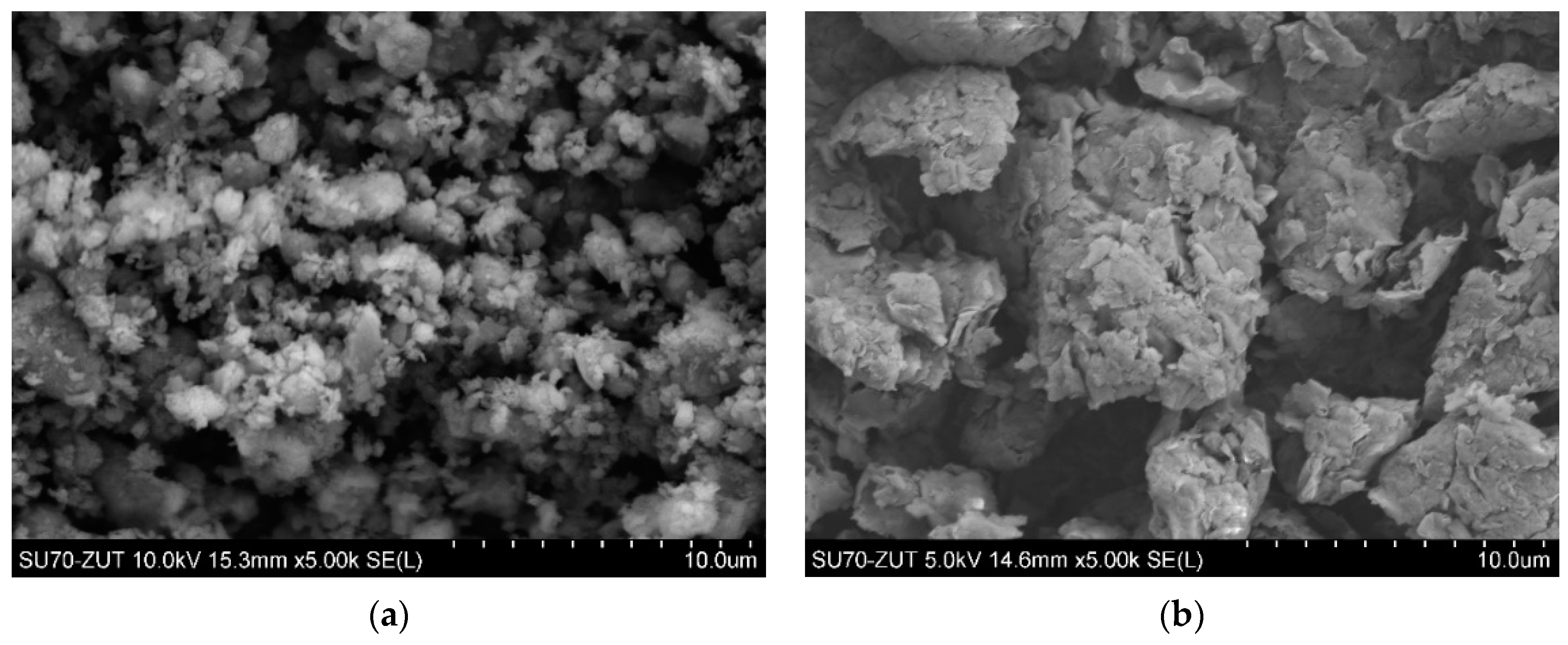
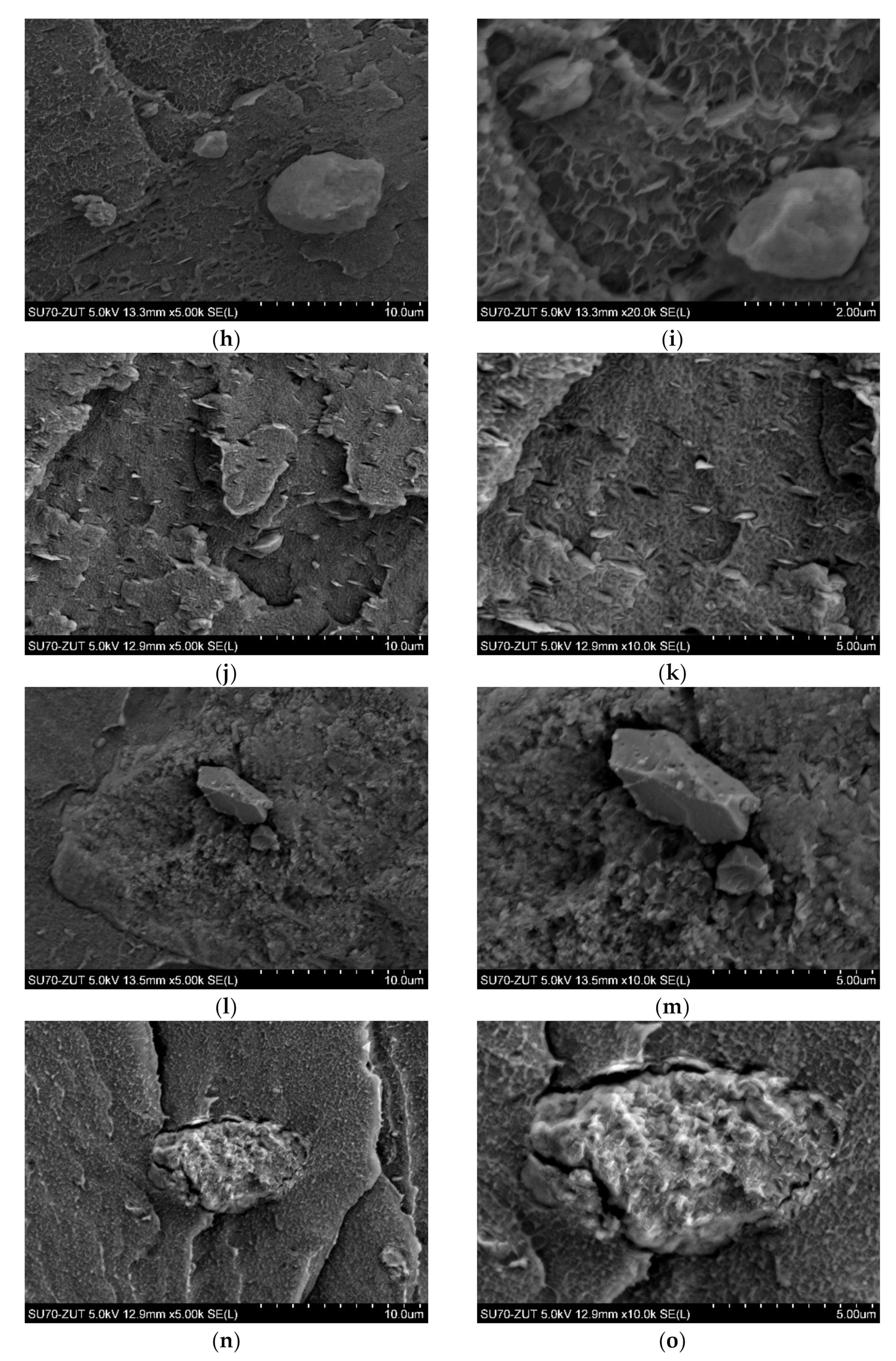
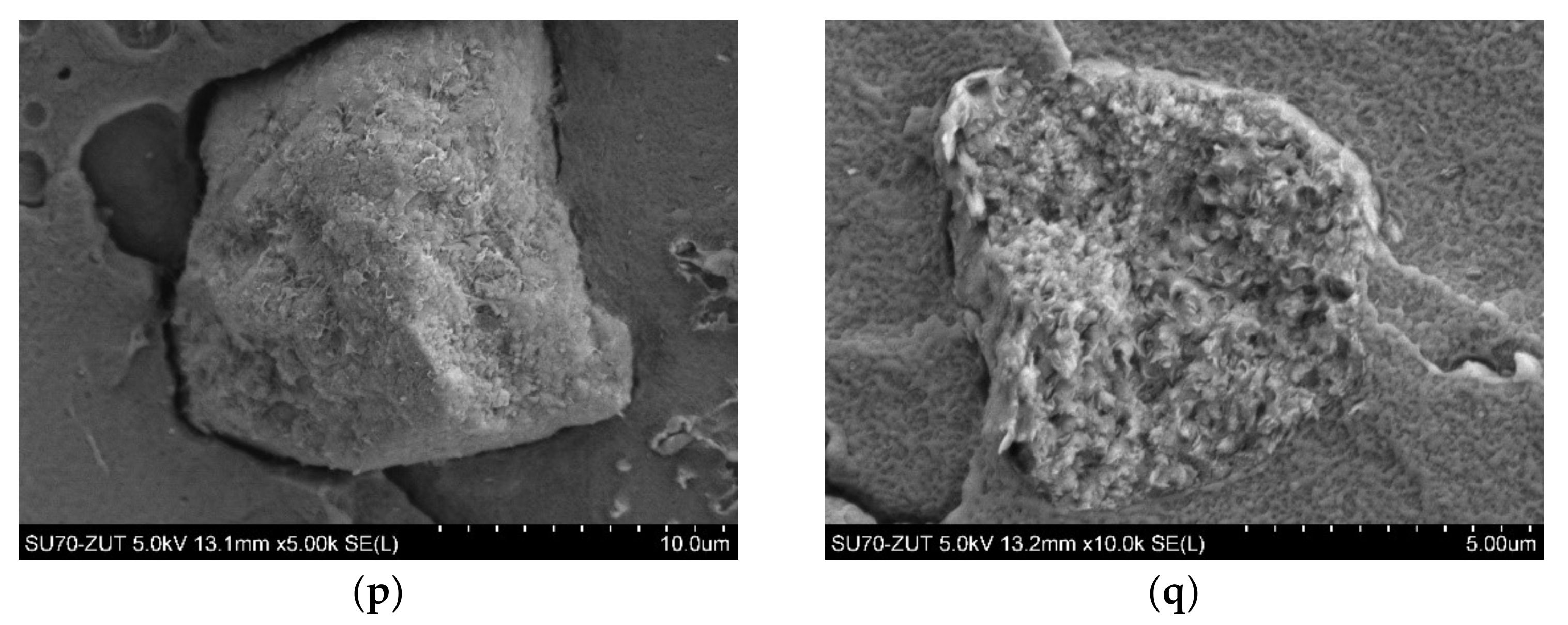
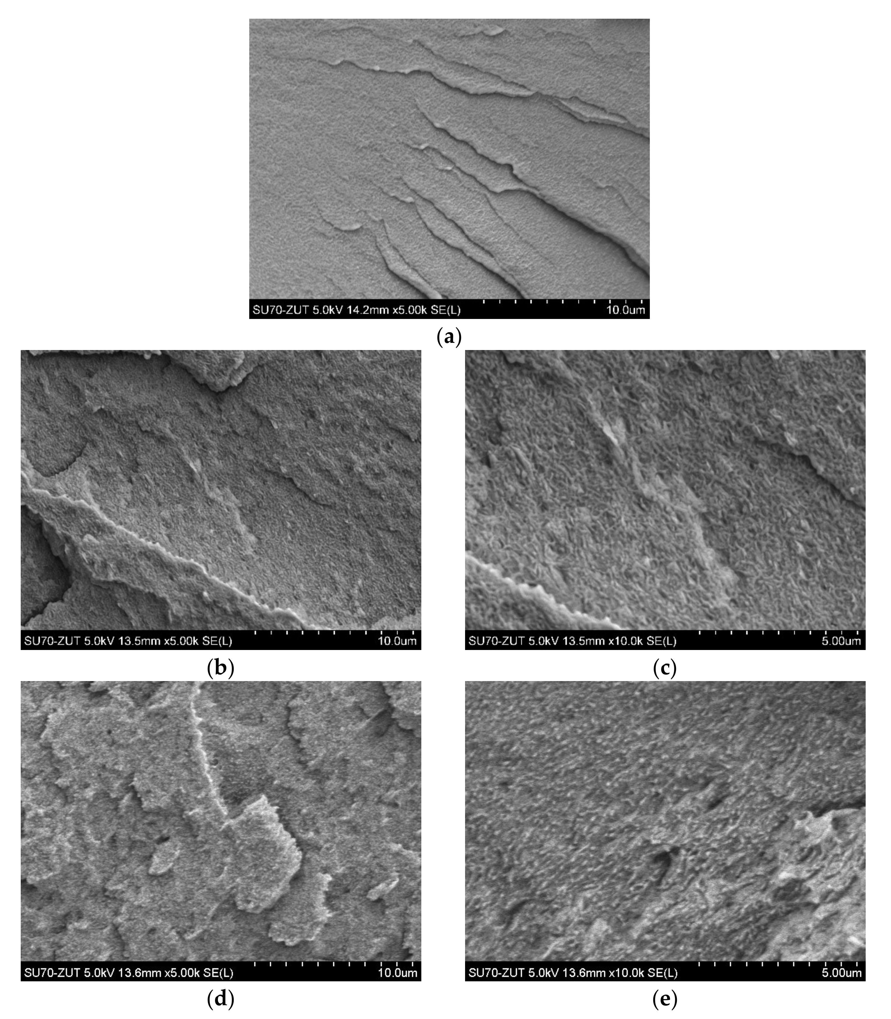
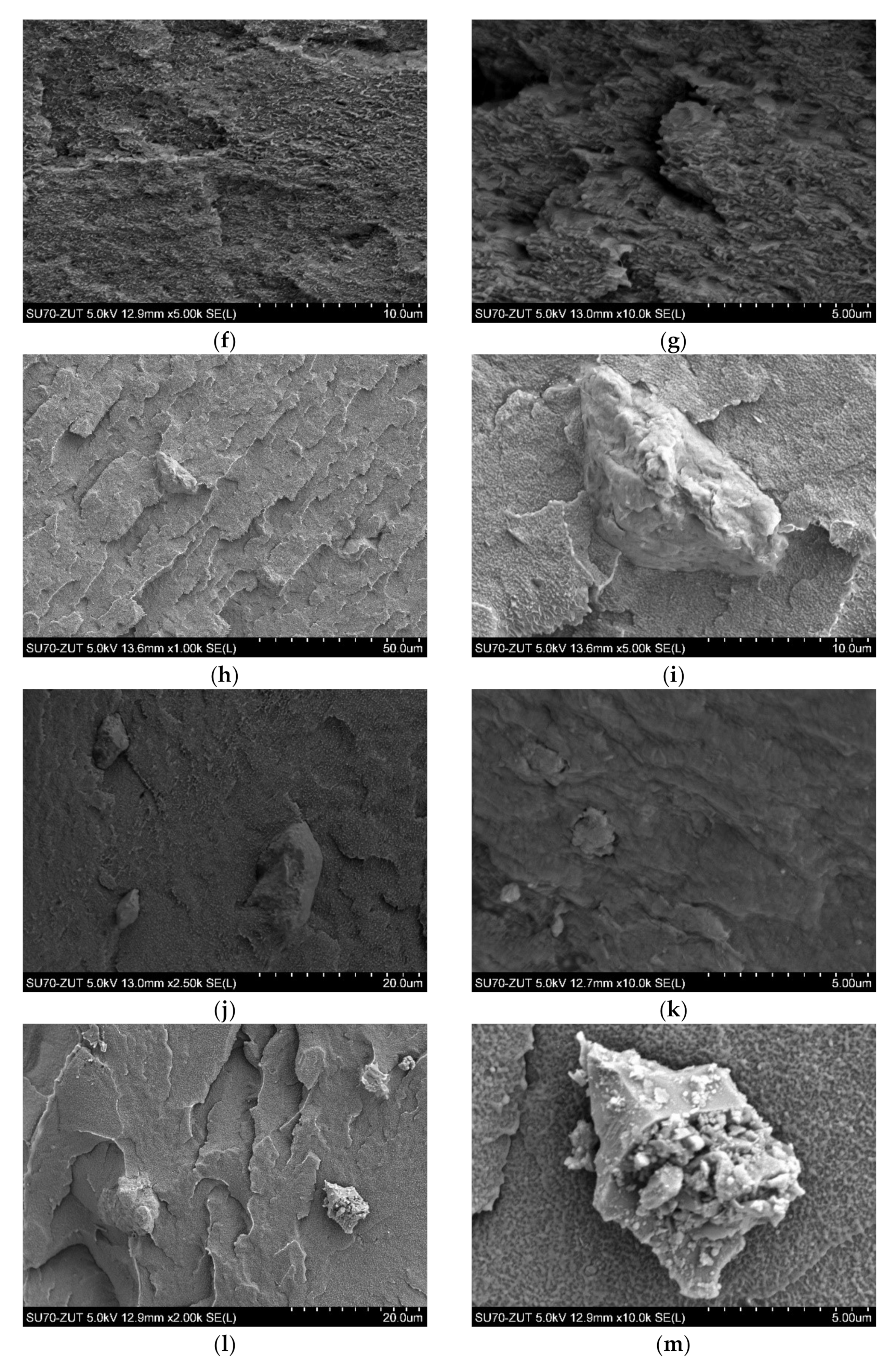
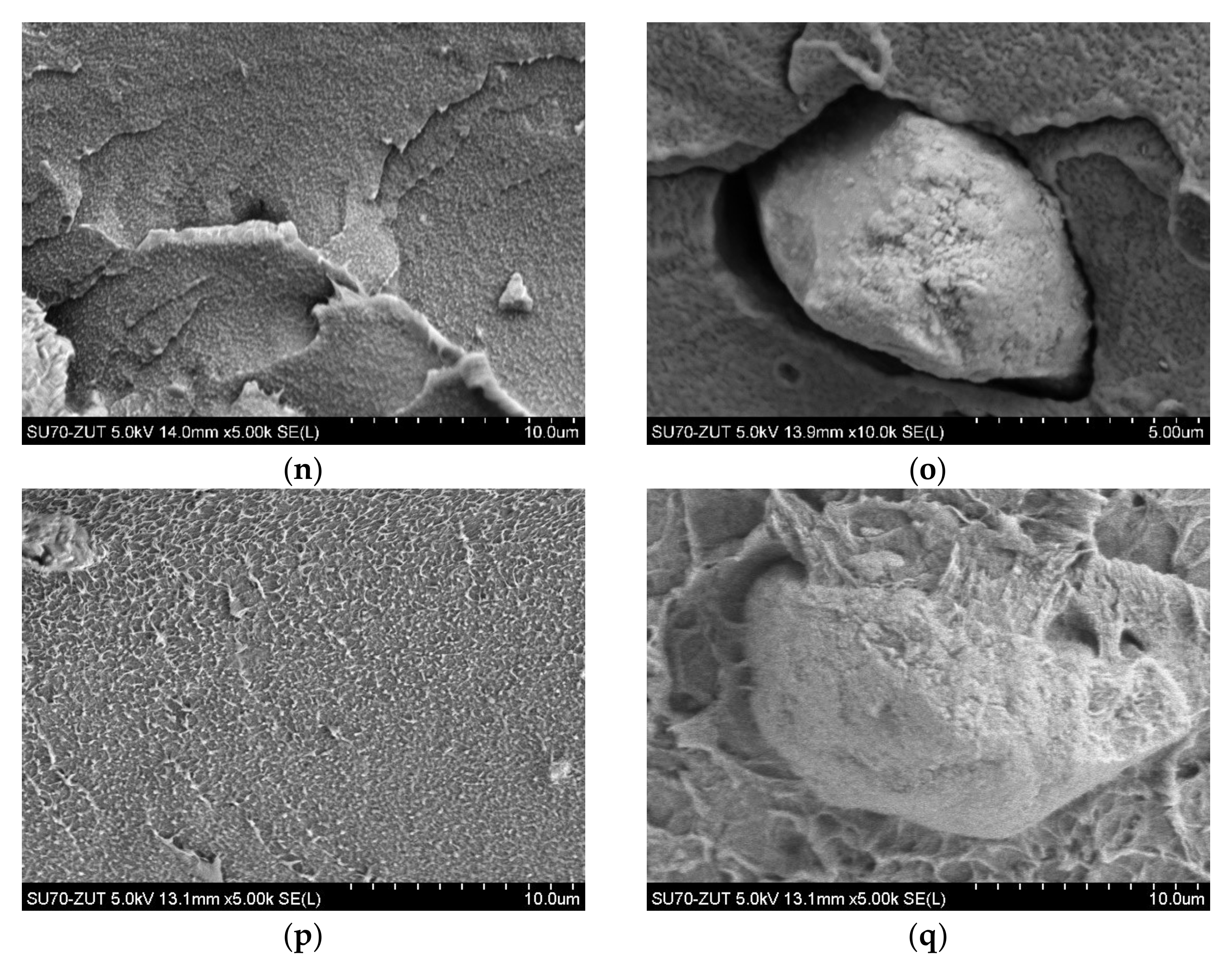
3.1. Morphology
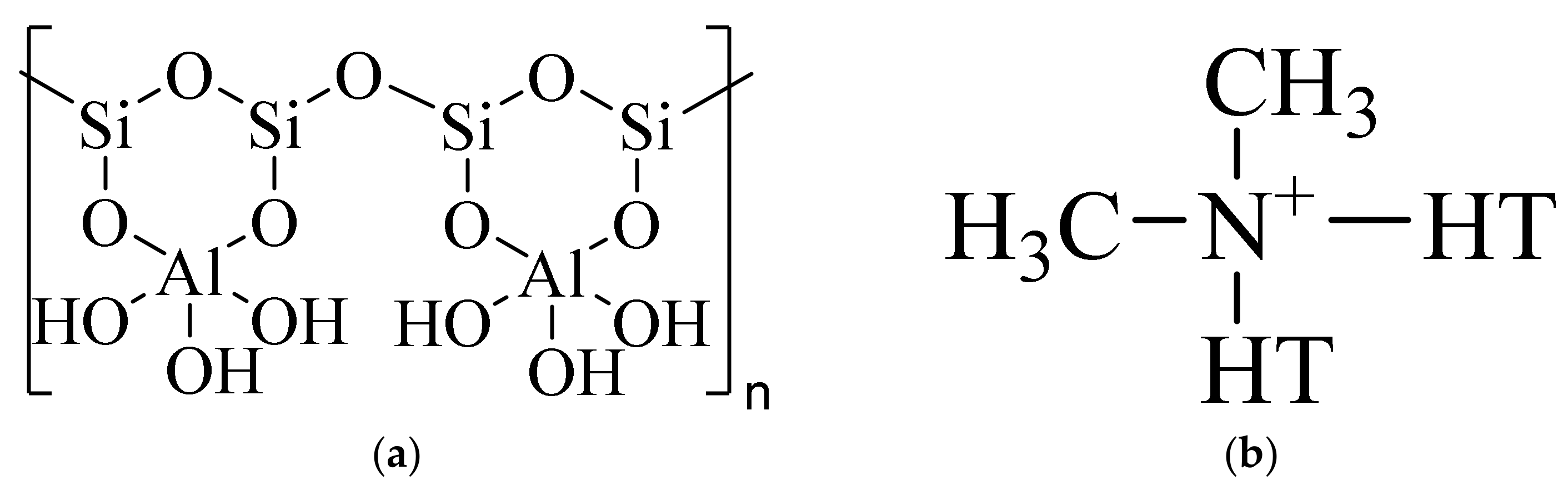
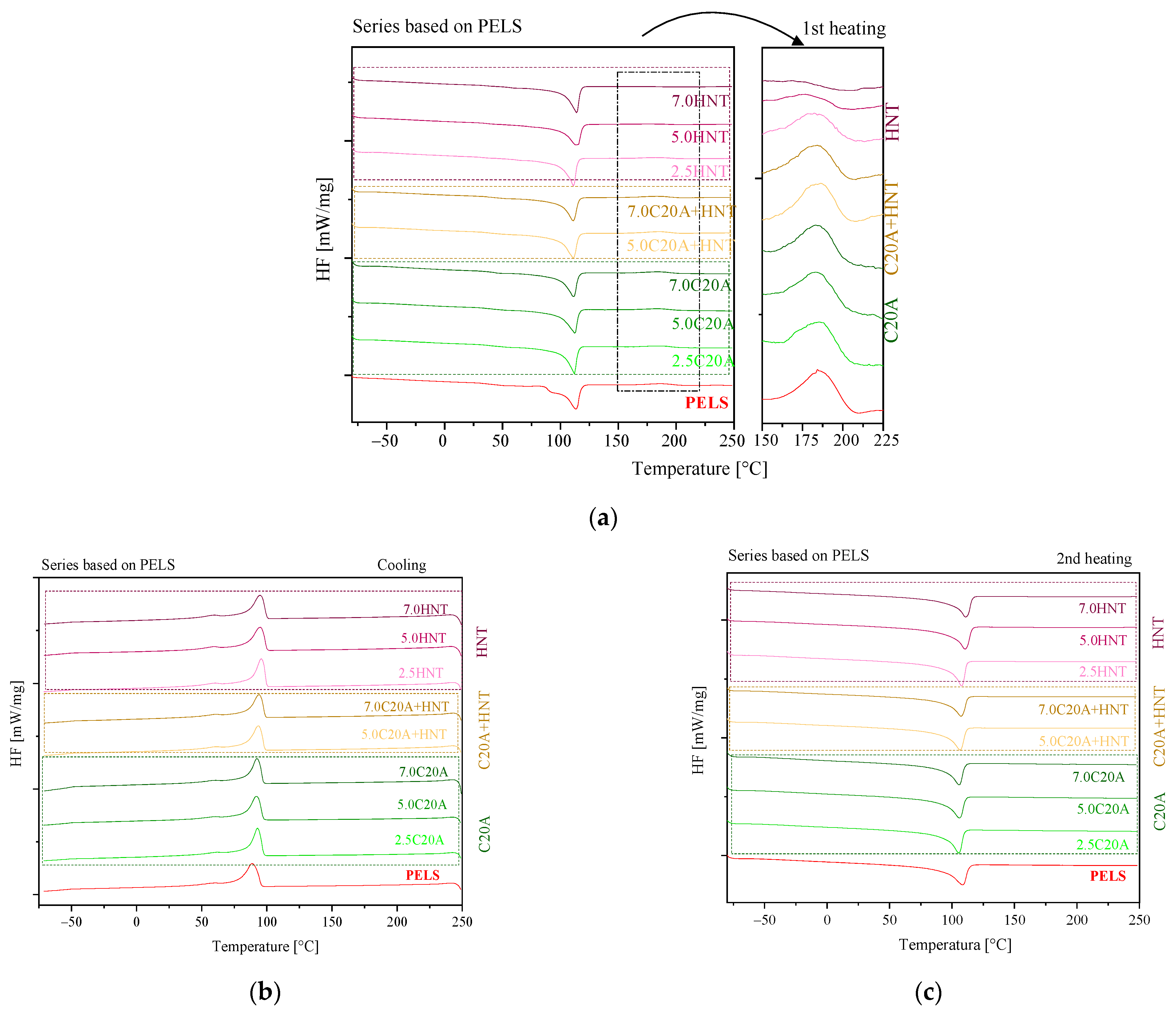
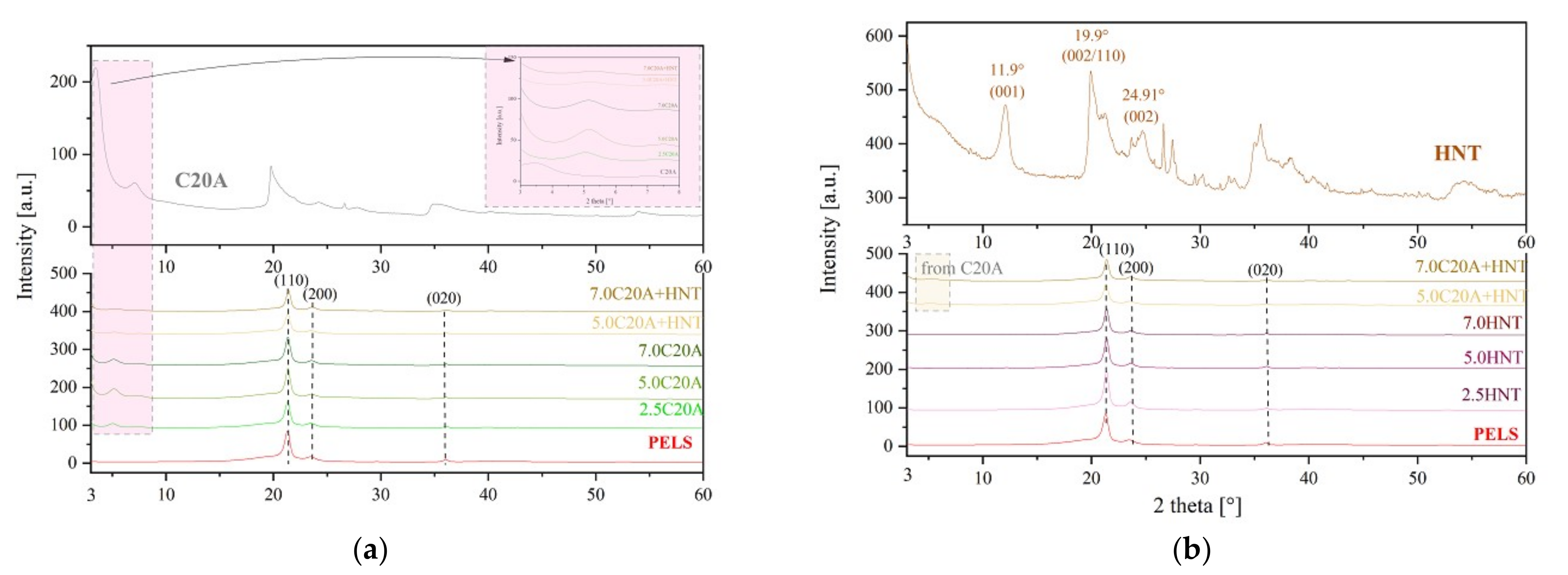
3.2. Structural Characterization of Polymer Nanocomposites
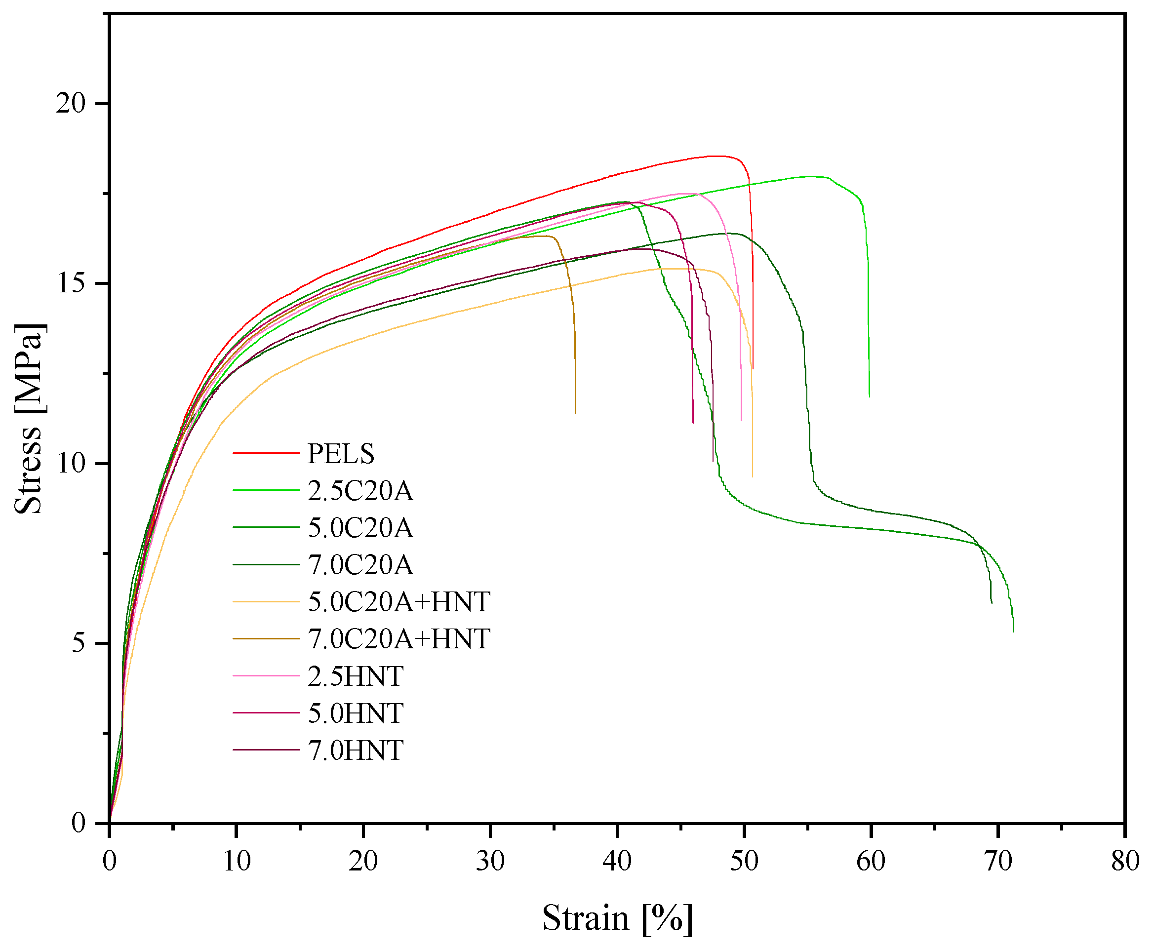
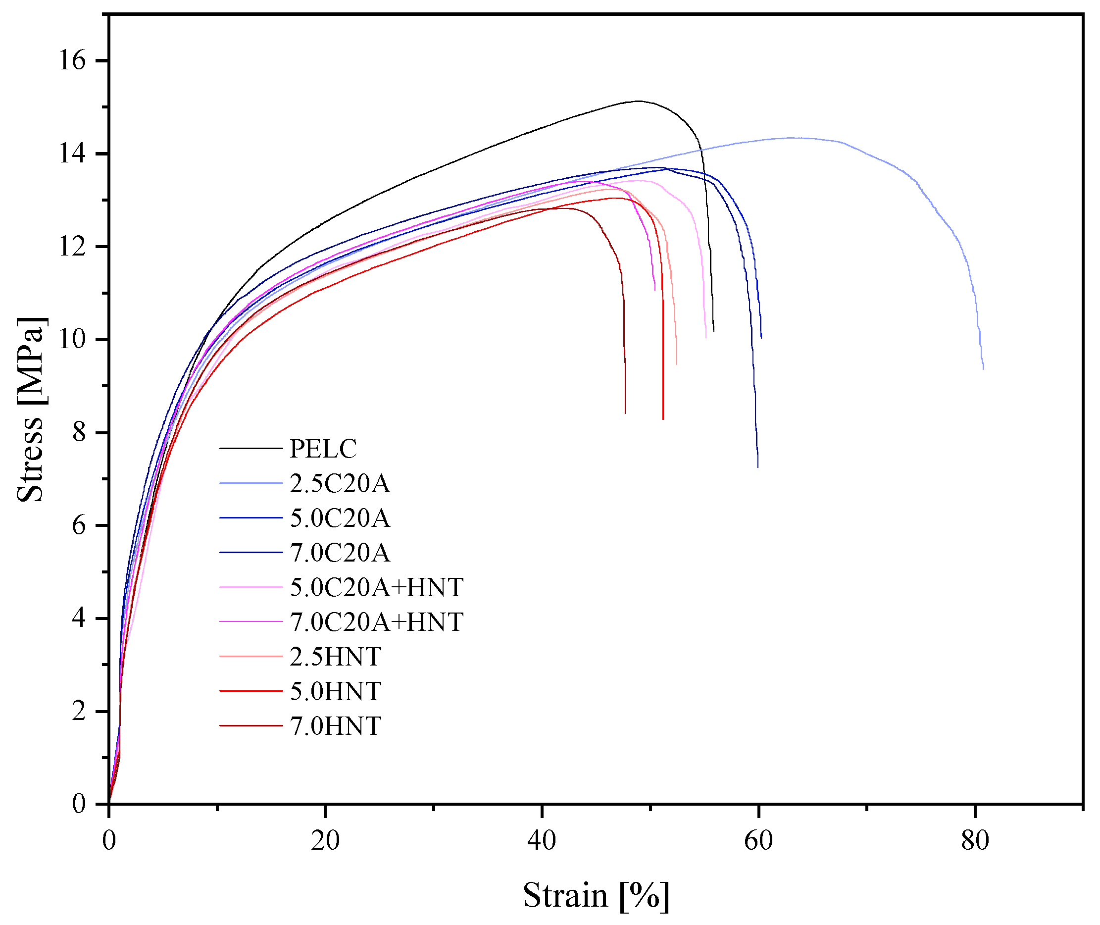
3.3. Mechanical Properties
3.4. Utilitarian Properties
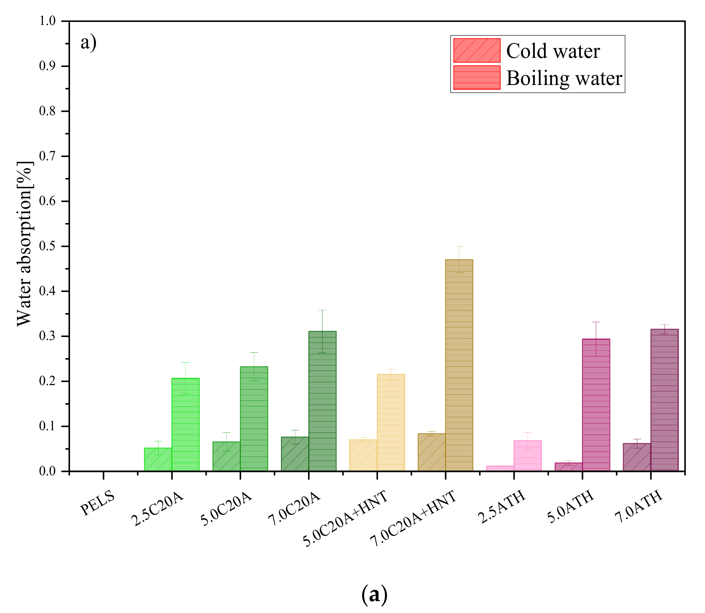
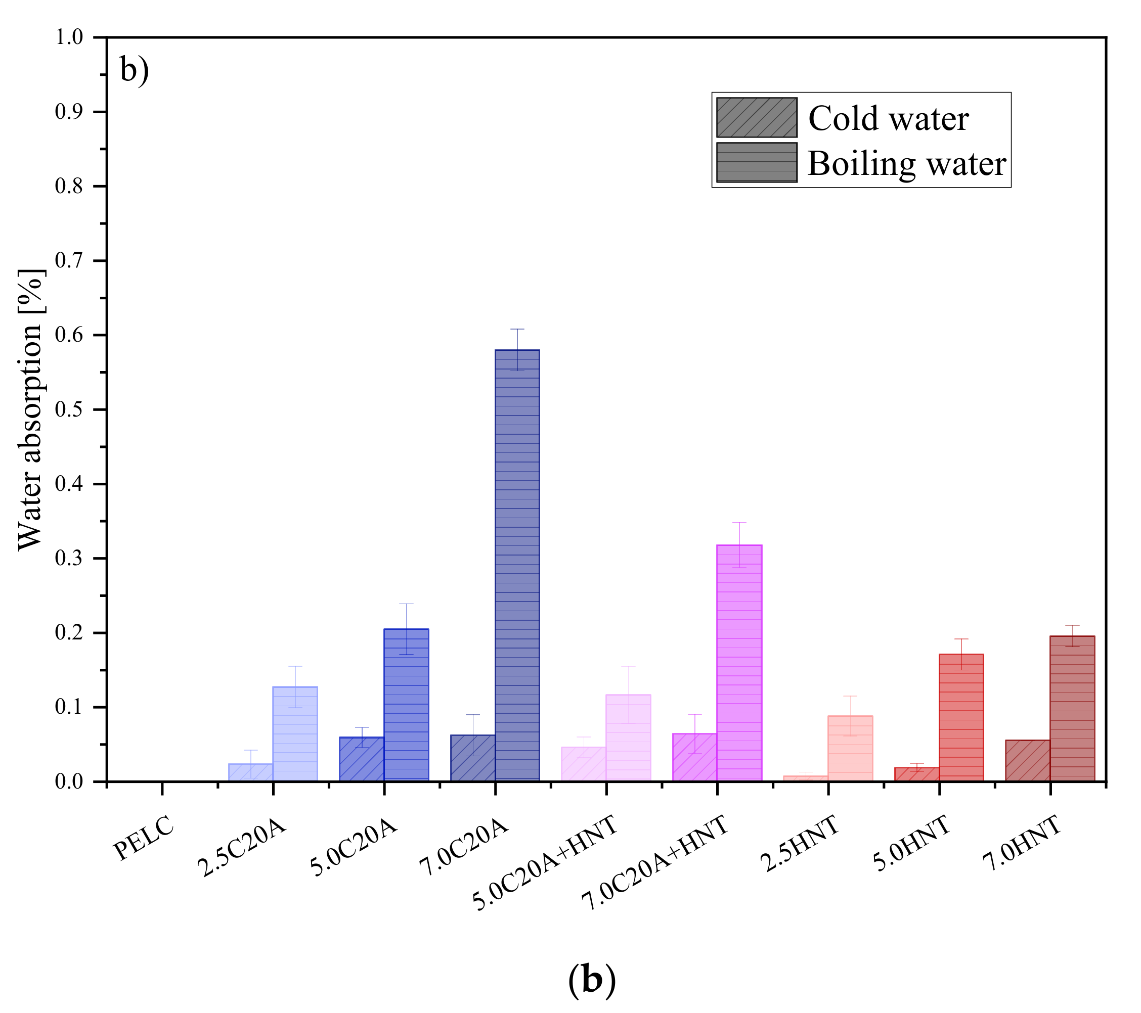
3.4.1. Water Absorption
3.4.2. TGA
3.4.3. Volume Resistivity
4. Conclusions
Author Contributions
Funding
Institutional Review Board Statement
Informed Consent Statement
Data Availability Statement
Conflicts of Interest
References
- Hampton, N.; Hartlein, R.; Lennartsson, H.; Orton, H.; Ramachandran, R. Long-Life XLPE Insulated Power Cable. In Proceedings of the 7th International Conference on Insulated Power Cables JICABLE, Paris, France, 24–28 June 2007; pp. 1–6. [Google Scholar]
- Orton, H. History of underground power cables. IEEE Electr. Insul. Mag. 2013, 29, 52–57. [Google Scholar] [CrossRef]
- Beyer, G. The Global Cable Industry; John Wiley and Sons: Hoboken, NJ, USA, 2021; ISBN 9783527346271. [Google Scholar]
- Ross, R.; Smit, J.J. Composition and Growth of Water Trees in XLPE. IEEE Trans. Electr. Insul. 1992, 27, 519–531. [Google Scholar] [CrossRef]
- Nikolajevic, S.V.; Drca, R. Effect of water on aging of XLPE cable insulation. Electr. Power Syst. Res. 2001, 60, 9–15. [Google Scholar] [CrossRef]
- Resner, L.; Paszkiewicz, S. Radial water barrier in submarine cables, current solutions and innovative development directions. Energies 2021, 14, 2761. [Google Scholar] [CrossRef]
- NNOSEA; JDR; RAMBOLL; IREC; COBRA; UL DEWI; WINDEUROPE; Lynch, M.; Wendt, F.; Schwarzkopf, M.-A. D3.1 Review of the State of the Art of Dynamic Cable System Design; Corewind: Barcelona, Spain, 2020. [Google Scholar]
- Gulski, E.; Anders, G.J.; Jongen, R.A.; Parciak, J.; Siemiński, J.; Piesowicz, E.; Paszkiewicz, S.; Irska, I. Discussion of electrical and thermal aspects of offshore wind farms’ power cables reliability. Renew. Sustain. Energy Rev. 2021, 151, 111580. [Google Scholar] [CrossRef]
- Andrews, T.; Pye, A.; Stevens, G.C.; German, I.; Rhodes, R.; Neumann, A.; Hoyle, D. Self-repair, water blocking materials for sub-sea power cables. In Proceedings of the CIRED 2021—The 26th International Conference and Exhibition on Electricity Distribution, Online Conference, 20–23 September 2021; pp. 187–192. [Google Scholar] [CrossRef]
- Worzyk, T. Submarine Power Cables; Springer: Berlin, Germany, 2009; p. 1377. ISBN 9783642012693. [Google Scholar]
- Sun, Y.; Xu, Y.; Yang, W.; Jin, J.; Cao, X. A Study of water trees in polymers under different conditions. In Proceedings of the 2009 IEEE 9th International Conference on the Properties and Applications of Dielectric Materials, Harbin, China, 19–23 July 2009; pp. 224–227. [Google Scholar] [CrossRef]
- Zhou, K.; Li, K.; He, Y.; Zhu, G. A new insight into the influence of mechanical orientation on water tree propagation in abnormal water tree shapes. IEEE Trans. Dielectr. Electr. Insul. 2017, 24, 3878–3886. [Google Scholar] [CrossRef]
- Ajili, S.H.; Ebrahimi, N.G.; Khorasani, M.T. Study on thermoplastic polyurethane/polypropylene (TPU/PP) blend as a blood bag material. J. Appl. Polym. Sci. 2003, 89, 2496–2501. [Google Scholar] [CrossRef]
- Franciszczak, P.; Taraghi, I.; Paszkiewicz, S.; Meljon, A.; Piesowicz, E.; Burzyński, M. Effect of halloysite nanotube on mechanical properties, thermal stability and morphology of polypropylene and polypropylene/short kenaf fibers hybrid biocomposites. Materials 2020, 13, 4459. [Google Scholar] [CrossRef]
- Al-Marri, M.J.; Masoud, M.S.; Nassar, A.M.G.; Zagho, M.M.; Khader, M.M. Synthesis and characterization of poly(vinyl alcohol): Cloisite® 20A nanocomposites. J. Vinyl Addit. Technol. 2017, 23, 181–187. [Google Scholar] [CrossRef]
- Paszkiewicz, S.; Irska, I.; Taraghi, I.; Piesowicz, E.; Sieminski, J.; Zawisza, K.; Pypeć, K.; Dobrzynska, R.; Terelak-Tymczyna, A.; Stateczny, K.; et al. Halloysite nanotubes and silane-treated alumina trihydrate hybrid flame retardant system for high-performance cable insulation. Polymers 2021, 13, 2134. [Google Scholar] [CrossRef] [PubMed]
- Mallayan, S.; Prabhu, R.R.; Desai, B.M.A.; Velmurugan, R.; Sarathi, R.; Rao, B.N. Understanding the electrical, thermal and mechanical properties of LDPE-clay nanocomposites. Micro Nano Lett. 2019, 14, 650–655. [Google Scholar] [CrossRef]
- Said, M.; Seif, S.; Challita, G. Development of blown film linear low-density polyethylene–clay nanocomposites: Part A: Manufacturing process and morphology. J. Appl. Polym. Sci. 2020, 137, 48589. [Google Scholar] [CrossRef]
- Beesetty, P.; Kale, A.; Patil, B.; Doddamani, M. Mechanical behavior of additively manufactured nanoclay/HDPE nanocomposites. Compos. Struct. 2020, 247, 112442. [Google Scholar] [CrossRef]
- Li, X.; Xu, M.; Zhang, K.; Xie, D.; Cao, X.; Liu, X. Influence of organic intercalants on the morphology and dielectric properties of XLPE/montmorillonite nanocomposite dielectrics. IEEE Trans. Dielectr. Electr. Insul. 2014, 21, 1705–1717. [Google Scholar] [CrossRef]
- Jose, J.P.; Thomas, S. Alumina-clay nanoscale hybrid filler assembling in cross-linked polyethylene based nanocomposites: Mechanics and thermal properties. Phys. Chem. Chem. Phys. 2014, 16, 14730–14740. [Google Scholar] [CrossRef]
- Jose, J.P.; Abraham, J.; Maria, H.J.; Varughese, K.T.; Thomas, S. Contact Angle Studies in XLPE Hybrid Nanocomposites with Inorganic Nanofillers. Macromol. Symp. 2016, 366, 66–78. [Google Scholar] [CrossRef]
- Ashish Sharad, P.; Kumar, K.S. Application of surface-modified XLPE nanocomposites for electrical insulation- partial discharge and morphological study. Nanocomposites 2017, 3, 30–41. [Google Scholar] [CrossRef]
- Kavitha, D.; Balachandran, M. XLPE–layered silicate nanocomposites for high voltage insulation applications: Dielectric characteristics, treeing behaviour and mechanical properties. IET Sci. Meas. Technol. 2019, 13, 1019–1025. [Google Scholar] [CrossRef]
- Bhattacharya, M. Polymer nanocomposites-A comparison between carbon nanotubes, graphene, and clay as nanofillers. Materials 2016, 9, 262. [Google Scholar] [CrossRef]
- Ravichandran, G.; Rathnakar, G.; Santhosh, N. Effect of heat treated HNT on physico-mechanical properties of epoxy nanocomposites. Compos. Commun. 2019, 13, 42–46. [Google Scholar] [CrossRef]
- Thomas, J.; Thomas, S.; Ahmad, Z. Materials Horizons: From Nature to Nanomaterials Crosslinkable Polyethylene; Springer: Singapore, 2021; ISBN 9789811605130. [Google Scholar]
- Liu, S.P. Flame retardant and mechanical properties of polyethylene/magnesium hydroxide/montmorillonite nanocomposites. J. Ind. Eng. Chem. 2014, 20, 2401–2408. [Google Scholar] [CrossRef]
- Pleşa, I.; Noţingher, P.V.; Schlögl, S.; Sumereder, C.; Muhr, M. Properties of polymer composites used in high-voltage applications. Polymers 2016, 8, 173. [Google Scholar] [CrossRef]
- Lim, K.S.; Mariatti, M.; Kamarol, M.; Ghani, A.B.A.; Shafi Halim, H.; Abu Bakar, A. Properties of nanofillers/crosslinked polyethylene composites for cable insulation. J. Vinyl Addit. Technol. 2019, 25, E147–E154. [Google Scholar] [CrossRef]
- Polanský, R.; Kadlec, P.; Slepička, P.; Kolská, Z.; Švorčík, V. Testing the applicability of LDPE/HNT composites for cable core insulation. Polym. Test. 2019, 78, 105993. [Google Scholar] [CrossRef]
- Perthué, A.; Bussière, P.O.; Baba, M.; Larche, J.F.; Gardette, J.L.; Therias, S. Correlation between water uptake and loss of the insulating properties of PE/ATH composites used in cables applications. Polym. Degrad. Stab. 2016, 127, 79–87. [Google Scholar] [CrossRef]
- Yu, Q.; Li, X.; Zhang, P.; Yang, P.; Chen, Y. Properties of water tree growing in XLPE and composites. In Proceedings of the 2019 2nd International Conference on Electrical Materials and Power Equipment (ICEMPE), Guangzhou, China, 7–10 April 2019; pp. 409–412. [Google Scholar] [CrossRef]
- Peila, R.; Lengvinaite, S.; Malucelli, G.; Priola, A.; Ronchetti, S. Modified organophilic montmorillonites/LDPE nanocomposites: Preparation and thermal characterization. J. Therm. Anal. Calorim. 2008, 91, 107–111. [Google Scholar] [CrossRef]


| Material | Tc [°C] | ΔHc [J/g] | Tm [°C] | ΔHm [J/g] | Tcl [°C] | ΔHcl [J/g] |
|---|---|---|---|---|---|---|
| PELS | 88.7 | 116.8 | 108.4 | 118.3 | 184.4 | 9.44 |
| PELS/2.5 C20A | 92.9 | 119.4 | 105.4 | 112.2 | 185.0 | 8.62 |
| PELS/5.0 C20A | 92.0 | 114 | 105.8 | 110.8 | 184.9 | 8.06 |
| PELS/7.0 C20A | 92.6 | 112.1 | 105.8 | 108.3 | 184.9 | 9.01 |
| PELS/5.0 C20A + HNT | 93.7 | 117.6 | 106.5 | 116.3 | 186.1 | 9.79 |
| PELS/7.0 C20A + HNT | 94.0 | 110.9 | 107.1 | 105.2 | 184.6 | 8.34 |
| PELS/2.5HNT | 95.8 | 123.0 | 107.9 | 119.7 | 184.4 | 6.38 |
| PELS/5.0HNT | 96.5 | 120.9 | 109.0 | 121.7 | 176.7 | 2.47 |
| PELS/7.0HNT | 96.8 | 120.1 | 109.7 | 114.3 | - | - |
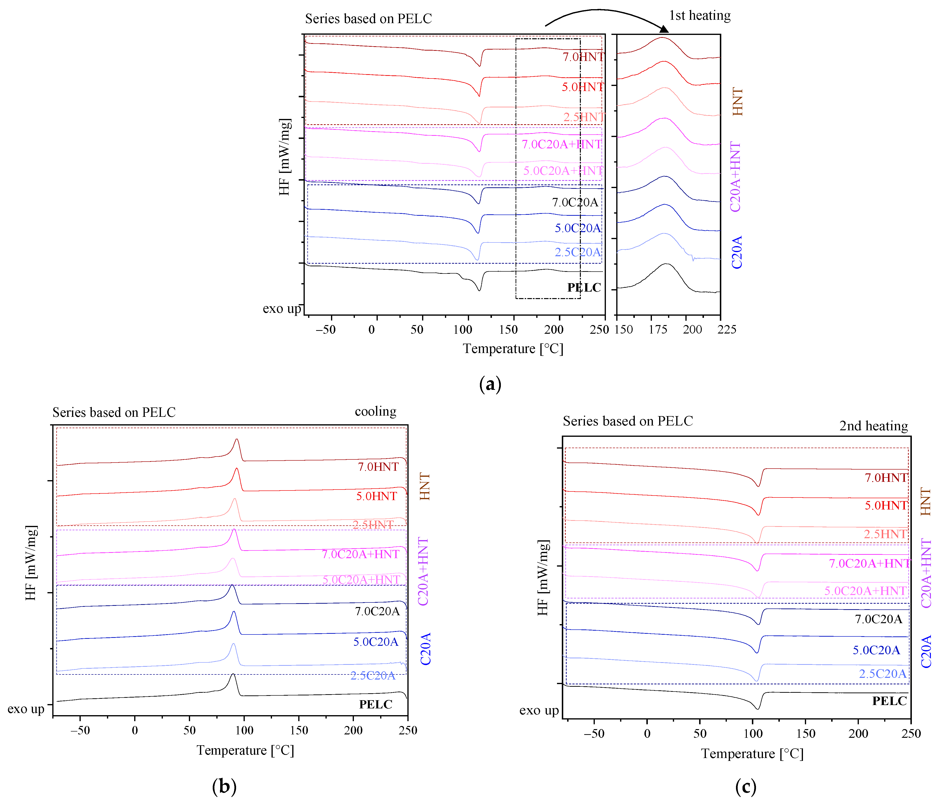
| Material | Tc [°C] | ΔHc [J/g] | Tm [°C] | ΔHm [J/g] | Tcl [°C] | ΔHcl [J/g] |
|---|---|---|---|---|---|---|
| PELC | 89.8 | 111.0 | 104.6 | 101.5 | 185.2 | 18.07 |
| PELC/2.5C20A | 90.3 | 106.0 | 103.8 | 103.8 | 184.2 | 13.55 |
| PELC/5.0 C20A | 90.6 | 114.3 | 104.0 | 99.57 | 184.2 | 14.01 |
| PELC/7.0 C20A | 89.1 | 101.9 | 105.4 | 101.3 | 184.1 | 12.87 |
| PELC/5.0 C20A + HNT | 89.6 | 105.9 | 105.3 | 122.5 | 185.2 | 14.59 |
| PELC/7.0 C20A + HNT | 91.0 | 104.7 | 104.3 | 99.86 | 184.5 | 14.47 |
| PELC/2.5HNT | 91.3 | 108.5 | 104.3 | 103.2 | 184.7 | 14.90 |
| PELC/5.0HNT | 93.2 | 107.0 | 105.6 | 122.9 | 183.9 | 12.41 |
| PELC/7.0HNT | 93.2 | 104.0 | 105.5 | 96.46 | 182.3 | 10.42 |
| Material | E [MPa] | [Mpa] | [%] | [Mpa] | [%] | Hardness [ShD] | Density |
|---|---|---|---|---|---|---|---|
| PELS | 199 ± 15.8 | 18.5 ± 0.2 | 48.3 ± 3.7 | 1.2 ± 0.1 | 50.6 ± 4.3 | 45.0 ± 0.3 | 0.929 ± 0.001 |
| PELS/2.5C20A | 223.3 ± 17.3 | 17.9 ± 1.4 | 55.0 ± 4.5 | 1.8 ± 0.1 | 59.8 ± 4.6 | 45.0 ± 0.2 | 0.943 ± 0.003 |
| PELS/5.0 C20A | 206.9 ± 16.9 | 17.2 ± 0.4 | 40.6 ± 2.8 | 2.7 ± 0.1 | 71.3 ± 6.5 | 45.0 ± 0.3 | 0.959 ± 0.002 |
| PELS/7.0 C20A | 335.6 ± 22.5 | 16.3 ± 0.5 | 49.0 ± 1.5 | 2.7 ± 0.2 | 69.6 ± 3.3 | 45.0 ± 0.3 | 0.960 ± 0.001 |
| PELS/5.0 C20A + HNT | 177.7 ±11.2 | 15.4 ± 0.6 | 44.0 ± 3.6 | 2.8 ± 0.1 | 50.7 ± 4.6 | 45.0 ± 0.5 | 0.956 ± 0.002 |
| PELS/7.0 C20A + HNT | 181.3 ± 10.4 | 16.2 ± 0.4 | 32.8 ± 1.9 | 1.9 ± 0.1 | 36.7 ± 2.8 | 45.0 ± 0.2 | 0.992 ± 0.006 |
| PELS/2.5HNT | 160.6 ± 12.6 | 17.5 ± 0.1 | 45.9 ± 2.5 | 3.3 ± 0.2 | 49.8 ± 2.2 | 46.0 ± 0.5 | 0.945 ± 0.002 |
| PELS/5.0HNT | 181.6 ± 13.3 | 17.2 ± 0.2 | 41.6 ± 2.8 | 2.8 ± 0.1 | 46.0 ± 3.8 | 47.0 + 0.5 | 0.963 ± 0.002 |
| PELS/7.0HNT | 213.9 ± 15.2 | 16.0 ± 0.6 | 42.5 ± 3.3 | 2.8 ± 0.1 | 47.5 ± 4.3 | 47.0 + 0.3 | 0.986 ± 0.002 |
| Material | E [Mpa] | [Mpa] | [%] | [Mpa] | [%] | Hardness [ShD] | Density |
|---|---|---|---|---|---|---|---|
| PELC | 102.1 ± 9.8 | 15.1 ± 0.7 | 49.2 ± 3.9 | 2.3 ± 0.1 | 56.1 ± 4.4 | 39.0 ± 0.5 | 0.934 ± 0.004 |
| PELC/2.5C20A | 155.0 ± 11.2 | 14.3 ± 0.1 | 63.4 ± 3.0 | 2.4 ± 0.2 | 81.4 ± 7.0 | 40.0 ± 0.5 | 0.951 ± 0.026 |
| PELC/5.0 C20A | 153.0 ± 12.4 | 13.6 ± 0.3 | 52.3 ± 4.4 | 2.7 ± 0.1 | 60.5 ± 3.7 | 43.0 ± 0.5 | 0.958 ± 0.011 |
| PELC/7.0 C20A | 152.1 ± 14.7 | 13.6 ± 0.2 | 48.5 ± 1.8 | 2.5 ± 0.2 | 60.2 ± 2.1 | 43.0 ± 0.5 | 0.963 ± 0.003 |
| PELC/5.0 C20A + HNT | 127.8 ± 8.7 | 13.1 ± 0.3 | 49.2 ± 3.6 | 2.3 ± 0.1 | 55.2 ± 4.8 | 43.0 ± 0.3 | 0.953 ± 0.004 |
| PELC/7.0 C20A + HNT | 149.7 ± 10.3 | 13.4 ± 0.2 | 44.2 ± 2.1 | 1.9 ± 0.1 | 50.5 ± 3.6 | 43.0 ± 0.3 | 0.968 ± 0.005 |
| PELC/2.5HNT | 79.5 ± 6.5 | 13.2 ± 0.4 | 47.3 ± 4.2 | 1.3 ± 0.1 | 52.5 ± 4.1 | 43.0 ± 0.4 | 0.948 ± 0.002 |
| PELC/5.0HNT | 116 ± 10.7 | 13.0 ± 0.4 | 49.1 ± 3.5 | 2.3 ± 0.2 | 56.7 ± 5.1 | 43.0 + 0.5 | 0.955 ± 0.026 |
| PELC/7.0HNT | 99.4 ± 7.2 | 12.8 ± 0.4 | 42.1 ± 2.7 | 2.8 ± 0.2 | 62.8 ± 5.3 | 44.0 + 0.3 | 0.961 ± 0.008 |
| Material | T5% [°C] | T10% [°C] | T50% [°C] | T90% [°C] | R (700 °C) [%] | TDTG2 * [°C] | TDTG1 [°C] | TDTG2 [°C] |
|---|---|---|---|---|---|---|---|---|
| PELS | 336 | 408 | 434 | 453 | 0.69 | - | 434 | 533 |
| PELS/2.5 C20A | 311 | 385 | 434 | 477 | 3.48 | 308 | 441 | 525 |
| PELS/5.0 C20A | 298 | 392 | 460 | 482 | 4.97 | 302 | 472 | - |
| PELS/7.0 C20A | 315 | 408 | 455 | 481 | 4.68 | 306 | 462 | - |
| PELS/5.0 C20A + HNT | 289 | 375 | 448 | 486 | 3.89 | 292 | 410/469 | - |
| PELS/7.0 C20A + HNT | 305 | 377 | 448 | 495 | 7.38 | - | 398/468 | - |
| PELS/2.5HNT | 311 | 401 | 456 | 482 | 3.37 | 295 | 412/466 | - |
| PELS/5.0HNT | 312 | 415 | 449 | 482 | 4.89 | 304 | 448 | - |
| PELS/7.0HNT | 336 | 408 | 434 | 453 | 6.09 | - | 434 | 533 |
| PELC | 315 | 403 | 434 | 452 | 0.65 | - | 435 | 530 |
| PELC/2.5 C20A | 333 | 420 | 477 | 495 | 5.98 | - | 479 | - |
| PELC/5.0 C20A | 348 | 418 | 474 | 491 | 6.01 | - | 479 | - |
| PELC/7.0 C20A | 365 | 407 | 479 | 501 | 8.02 | - | 484 | - |
| PELC/5.0 C20A + HNT | 388 | 416 | 464 | 491 | 6.79 | 309 | 471 | - |
| PELC/7.0 C20A + HNT | 364 | 414 | 472 | 484 | 7.85 | - | 478 | - |
| PELC/2.5HNT | 322 | 397 | 443 | 486 | 3.95 | 305 | 445 | - |
| PELC/5.0HNT | 315 | 397 | 453 | 494 | 5.77 | 303 | 460 | - |
| PELC/7.0HNT | 311 | 397 | 452 | 498 | 7.80 | 297 | 457 | - |
| Material | Volume Resistivity ρs [Ω m] |
|---|---|
| PELS | 336 |
| PELS/2.5C20A | 311 |
| PELS/5.0C20A | 298 |
| PELS/7.0C20A | 315 |
| PELS/5.0C20A + HNT | 289 |
| PELS/7.0C20A + HNT | 305 |
| PELS/2.5HNT | 311 |
| PELS/5.0HNT | 312 |
| PELS/7.0HNT | 336 |
| PELC | 315 |
| PELC/2.5C20A | 333 |
| PELC/5.0C20A | 348 |
| PELC/7.0C20A | 365 |
| PELC/5.0C20A + HNT | 388 |
| PELC/7.0C20A + HNT | 364 |
| PELC/2.5HNT | 322 |
| PELC/5.0HNT | 315 |
| PELC/7.0HNT | 311 |
Publisher’s Note: MDPI stays neutral with regard to jurisdictional claims in published maps and institutional affiliations. |
© 2022 by the authors. Licensee MDPI, Basel, Switzerland. This article is an open access article distributed under the terms and conditions of the Creative Commons Attribution (CC BY) license (https://creativecommons.org/licenses/by/4.0/).
Share and Cite
Resner, L.; Lesiak, P.; Taraghi, I.; Kochmanska, A.; Figiel, P.; Piesowicz, E.; Zenker, M.; Paszkiewicz, S. Polymer Hybrid Nanocomposites Based on Homo and Copolymer Xlpe Containing Mineral Nanofillers with Improved Functional Properties Intended for Insulation of Submarine Cables. Polymers 2022, 14, 3444. https://doi.org/10.3390/polym14173444
Resner L, Lesiak P, Taraghi I, Kochmanska A, Figiel P, Piesowicz E, Zenker M, Paszkiewicz S. Polymer Hybrid Nanocomposites Based on Homo and Copolymer Xlpe Containing Mineral Nanofillers with Improved Functional Properties Intended for Insulation of Submarine Cables. Polymers. 2022; 14(17):3444. https://doi.org/10.3390/polym14173444
Chicago/Turabian StyleResner, Leszek, Pawel Lesiak, Iman Taraghi, Agnieszka Kochmanska, Pawel Figiel, Elzbieta Piesowicz, Marek Zenker, and Sandra Paszkiewicz. 2022. "Polymer Hybrid Nanocomposites Based on Homo and Copolymer Xlpe Containing Mineral Nanofillers with Improved Functional Properties Intended for Insulation of Submarine Cables" Polymers 14, no. 17: 3444. https://doi.org/10.3390/polym14173444