
Experimental and Theoretical Study on Flexural Behavior of GFRP- and CFRP-Reinforced Concrete Beams after High-Temperature Exposure


Abstract
:1. Introduction
2. Experimental Program
2.1. Test Specimens
2.2. Materials
2.2.1. Concrete
2.2.2. FRP Bars
2.3. Furnace Equipment and Instrumentation
2.4. Test Procedure
3. Results and Discussion
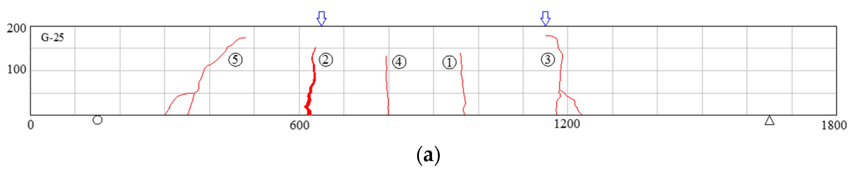
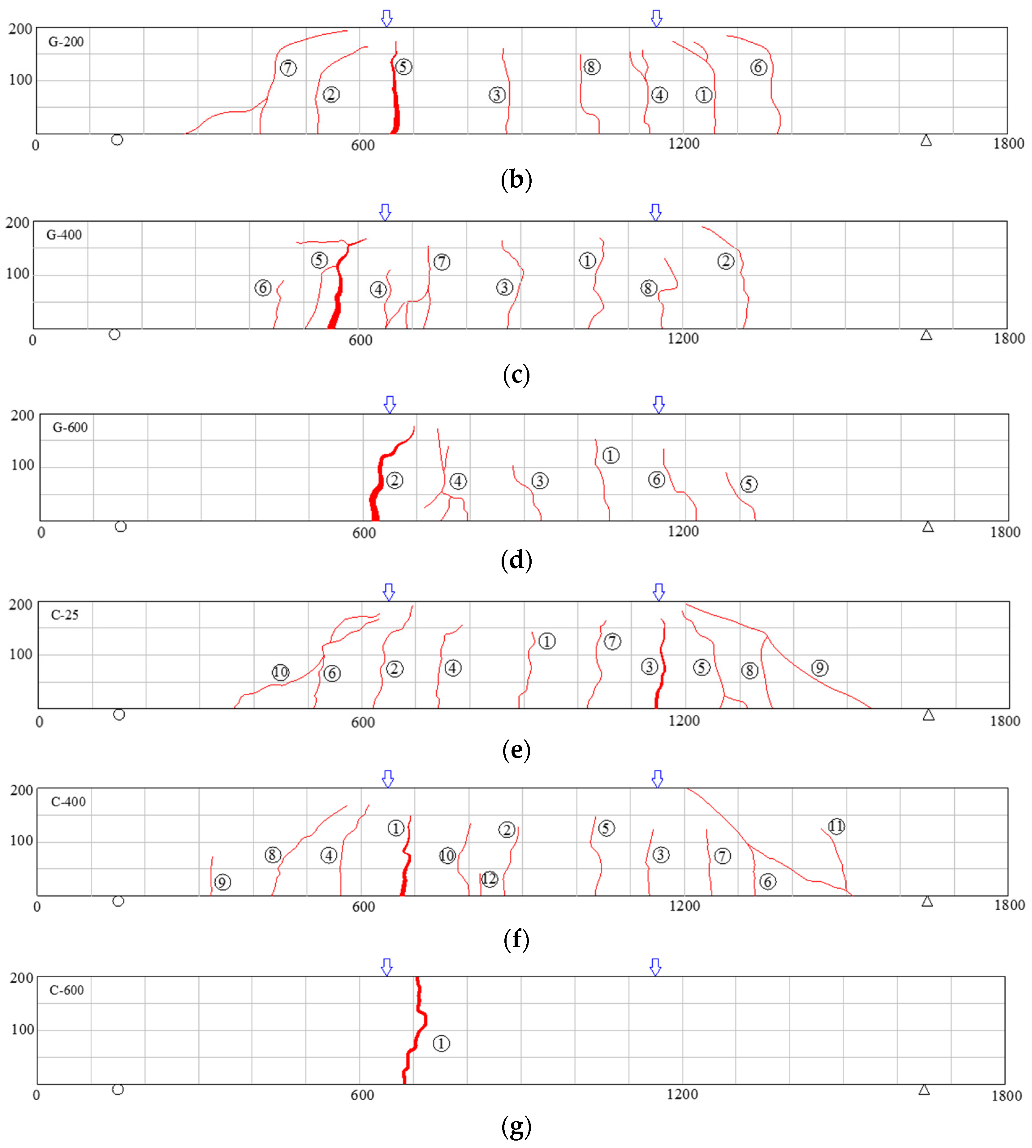
3.1. Cracking Behavior and Failure Modes
3.1.1. Crack Development Analysis
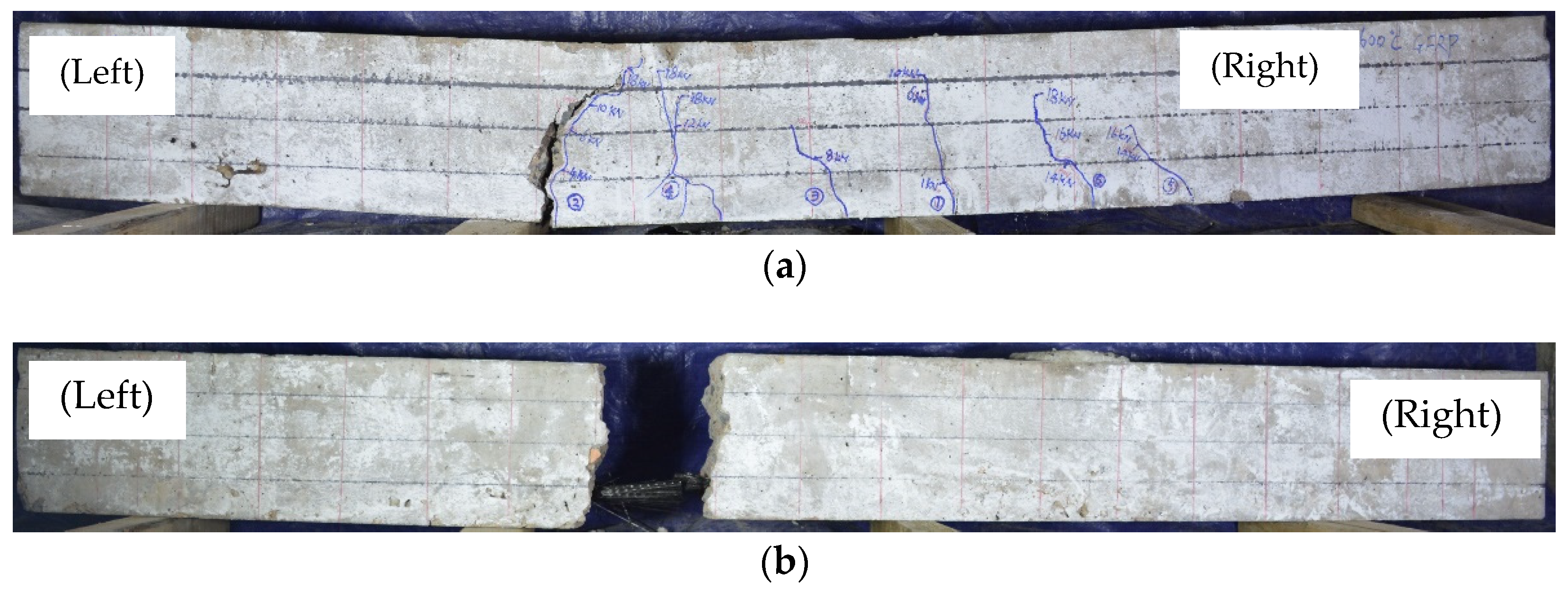
3.1.2. Failure Modes Analysis
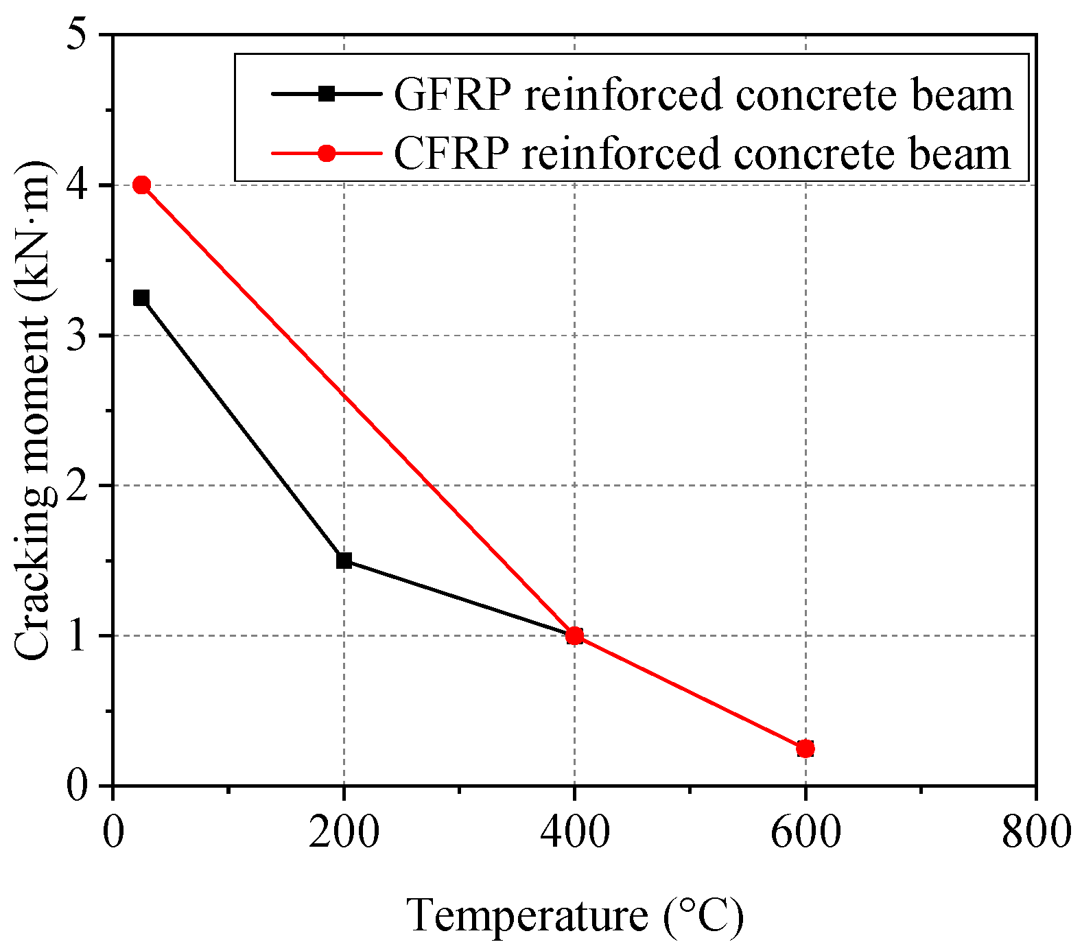
3.2. Cracking Load
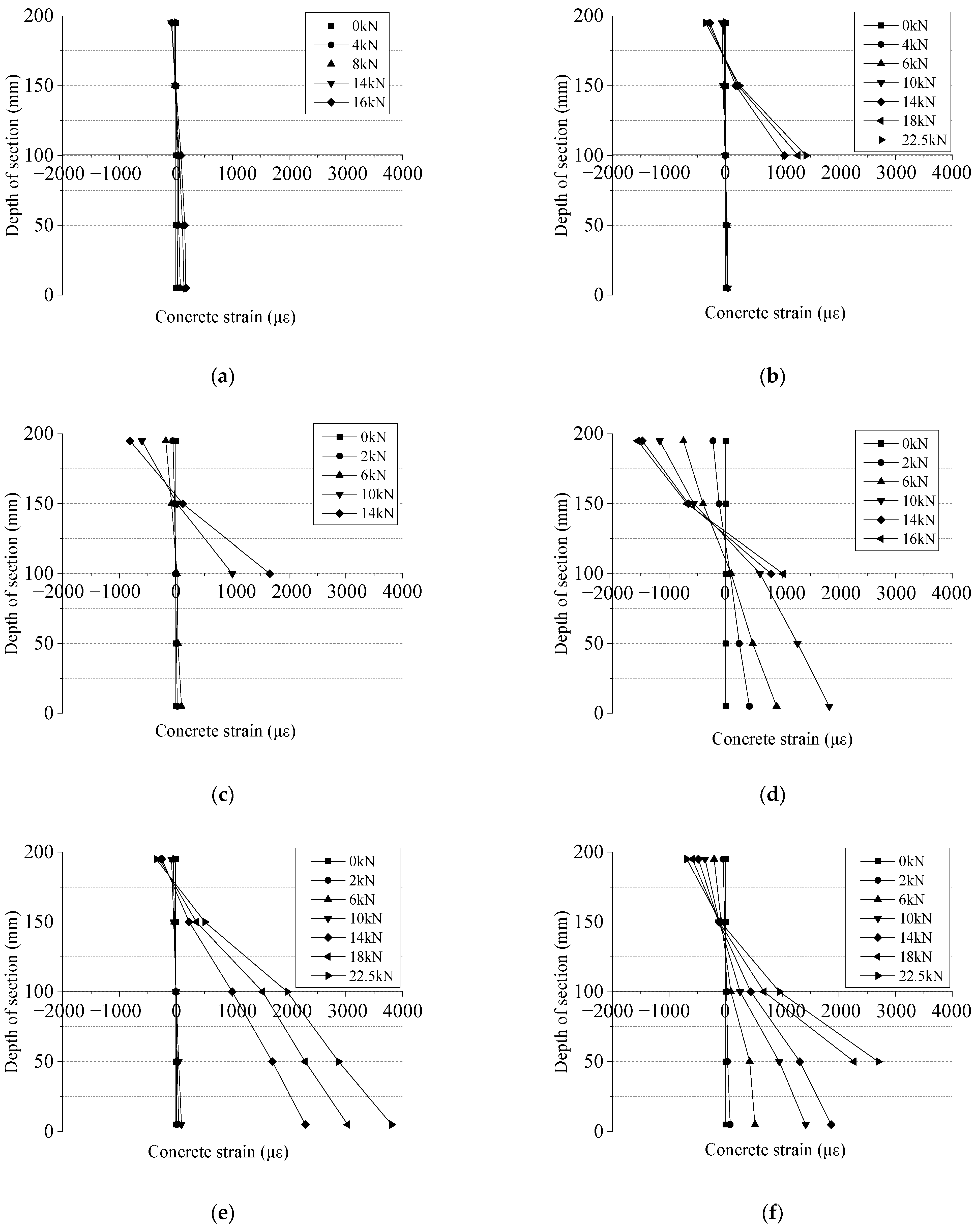
3.3. Concrete Strain
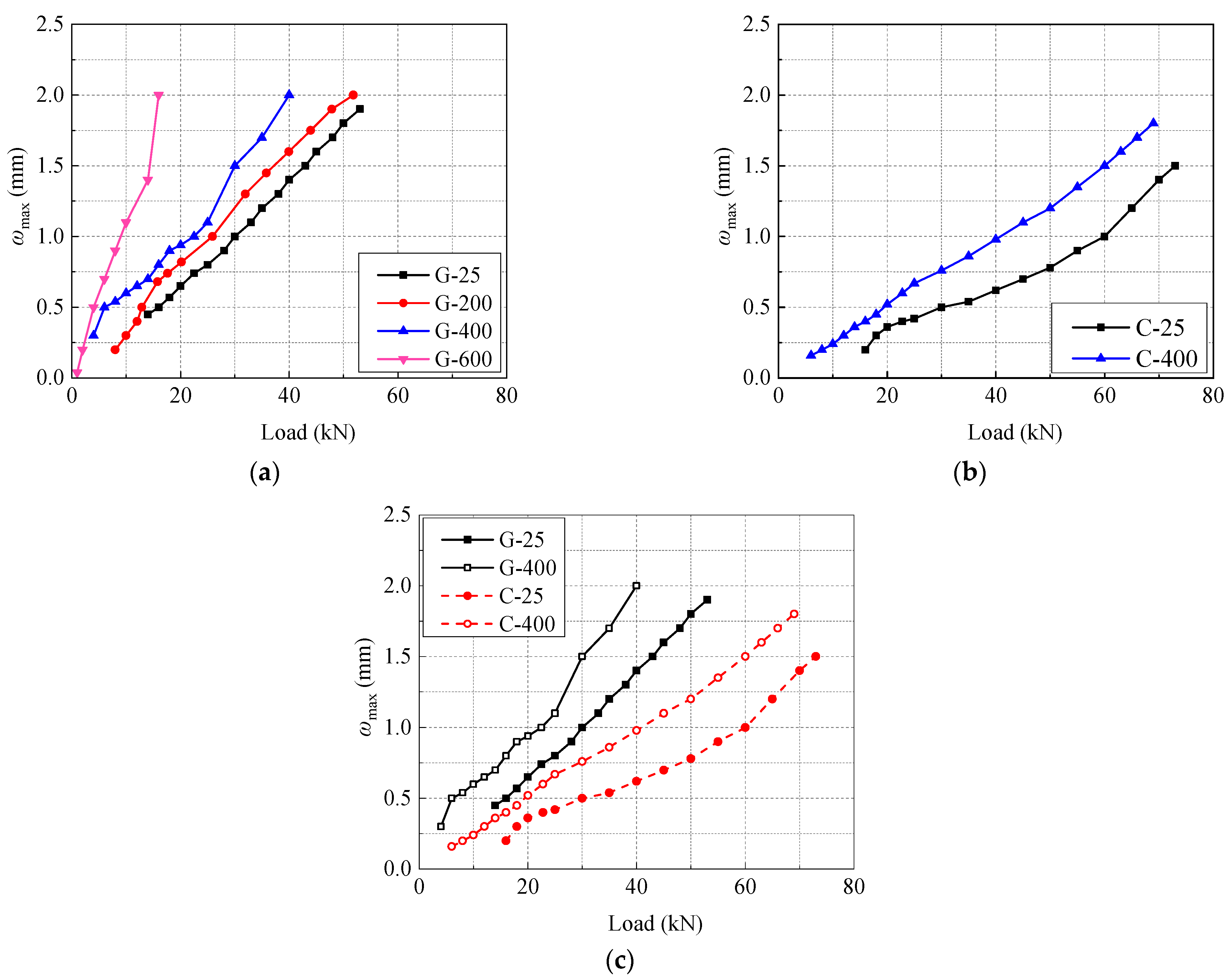
3.4. Maximum Crack Width Analysis
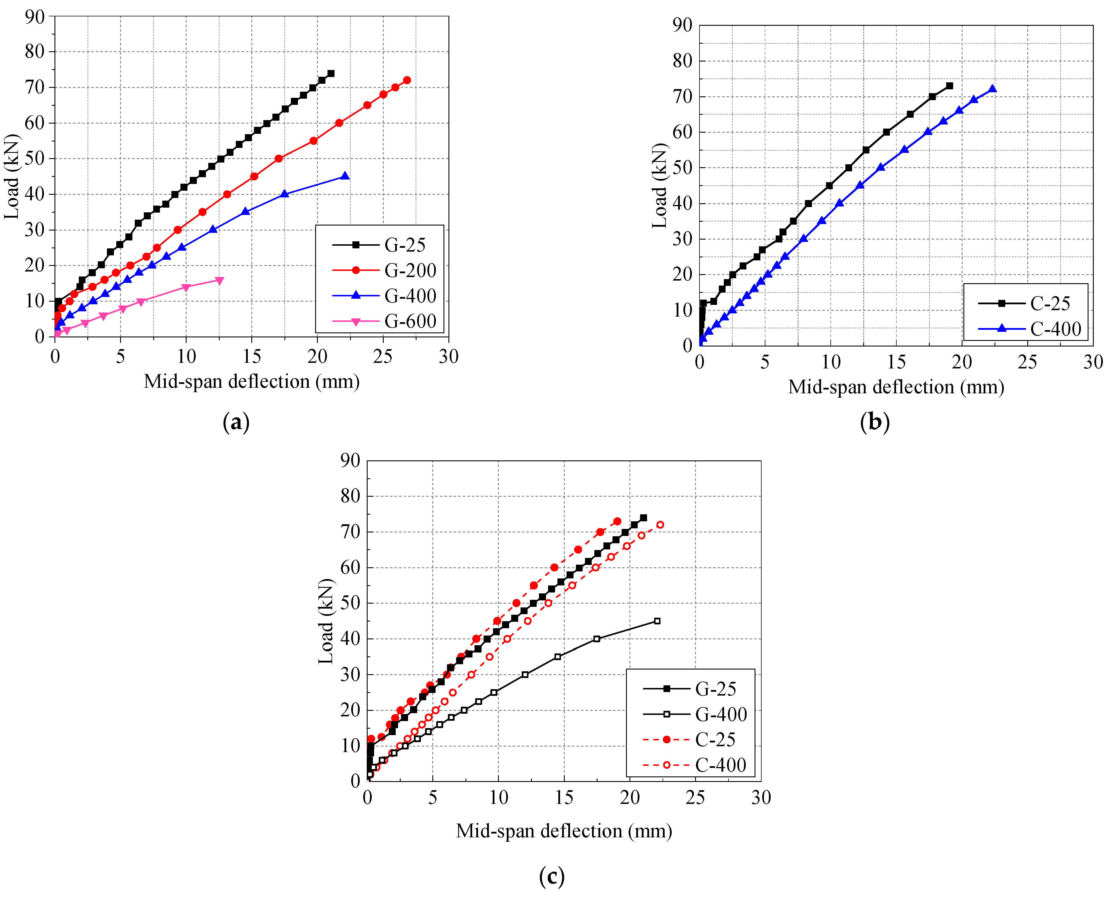
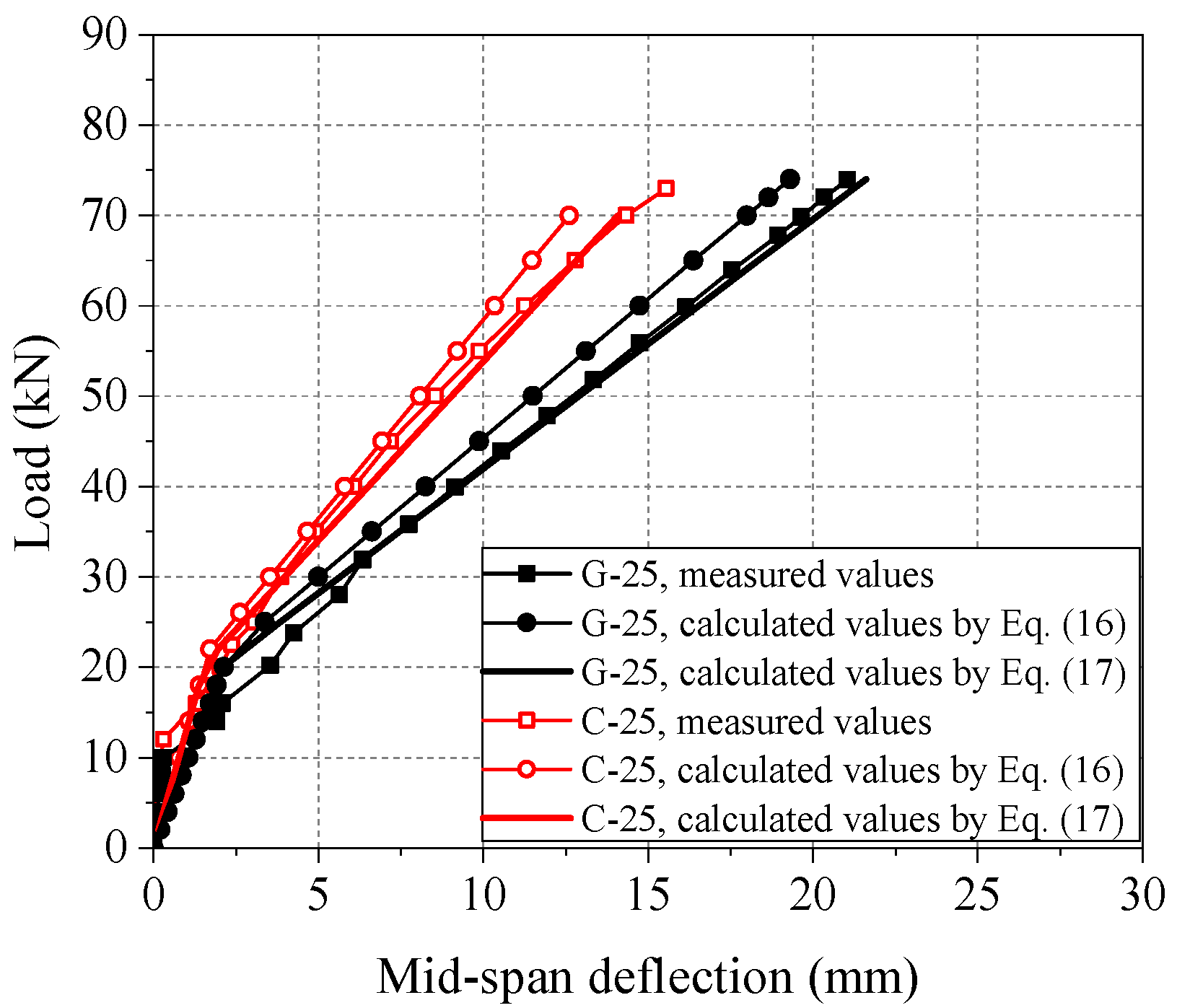
3.5. Load-Deflection Behavior
3.6. Bending Capacity Analysis
4. Theoretical Analysis
4.1. Calculation Method of Maximum Crack Width ωmax
4.1.1. Calculation Method of ωmax of FRP-Reinforced Concrete Beam at 25 °C
4.1.2. Calculation Method of ωmax of FRP-Reinforced Concrete Beam after High-Temperature Exposure
4.2. Calculation Method of Deflection
4.2.1. Short-Term Stiffness Bs of FRP-Reinforced Concrete Beams at Room Temperature
4.2.2. Short-Term Stiffness of FRP-Reinforced Concrete Beam after High-Temperature Exposure
4.3. Calculation Method of Bending Capacity of Cross Section of FRP-Reinforced Concrete Beams after High-Temperature Exposure
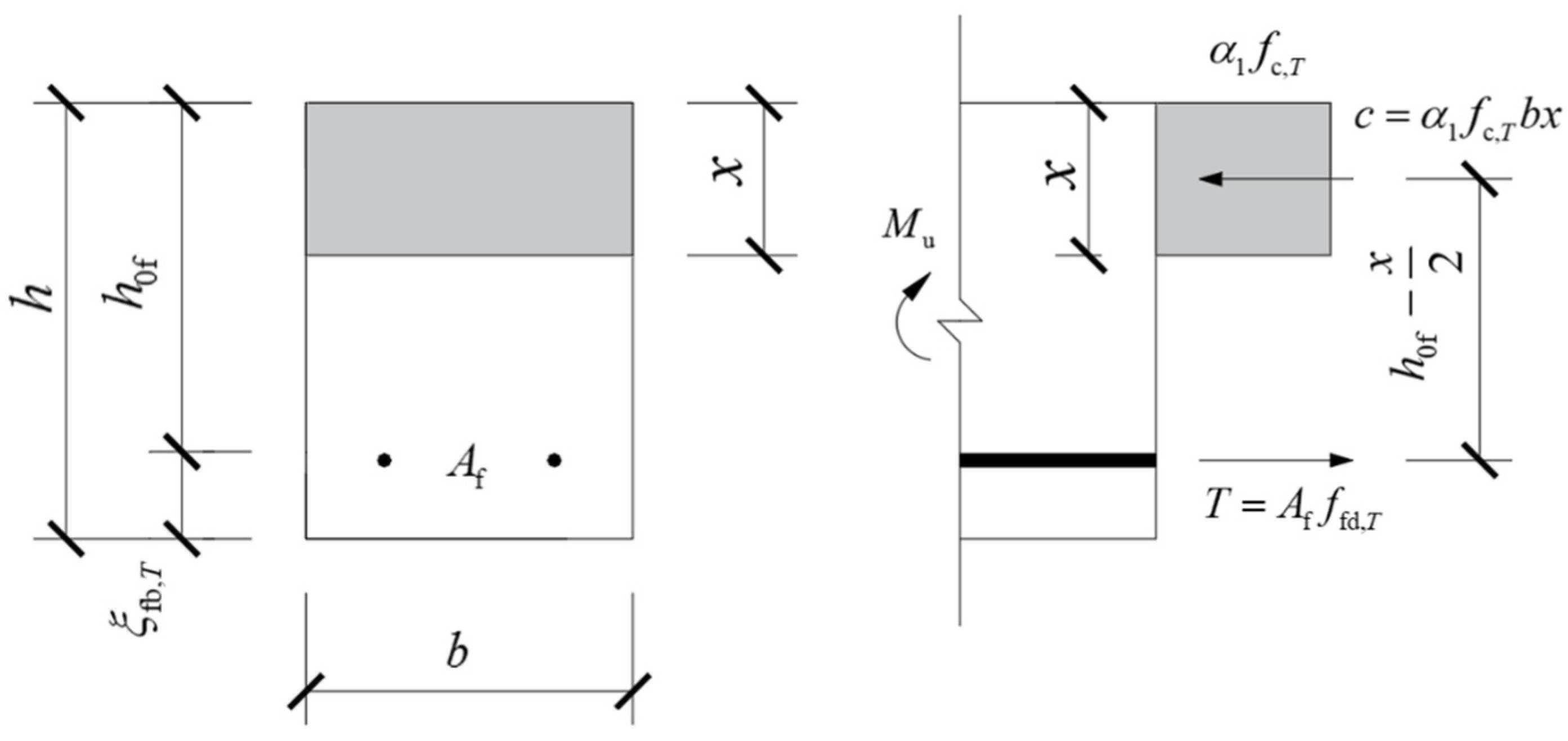
4.3.1. Balanced Relative Depth of Compressive Area ξfb,T after High-Temperature Exposure
4.3.2. Calculation Formula of Residual Bending Capacity of Cross Section after High-Temperature Exposure
4.3.3. Analysis of Calculation Results
5. Conclusions
- (1)
- The maximum crack width of FRP-reinforced concrete beams deteriorates obviously after high-temperature exposure. With an increase of exposure temperature from 25 °C to 600 °C, the maximum crack width of FRP beams increases gradually. The type of FRP bars has a significant influence on the maximum crack width of FRP-reinforced concrete beams. After exposure of 25 °C and 400 °C, the maximum crack width of GFRP-reinforced concrete beams is 55.7% and 51.0% higher than that of CFRP beams, respectively.
- (2)
- High temperature deteriorates the deformation resistance of GFRP-reinforced concrete beams obviously. With an increase in high temperature, the stiffness of FRP-reinforced concrete beams decreases obviously and the deflection increases. The type of FRP bars has a significant effect on the deflection of FRP-reinforced concrete beams. At 25 °C and 400 °C, the deflection of GFRP-reinforced concrete beams is 26.9% and 44.5% higher than that of CFRP beams, respectively.
- (3)
- The effect of high temperature on the bending capacity of the normal section of FRP-reinforced concrete beams is obvious. With the increase of high temperature, the bending capacity of the normal section of FRP beams decreases significantly. Especially at 600 °C, the bending capacity of the normal section of GFRP-reinforced concrete beams decreases to 76%, which was 4.5 kN·m, and the bending capacity of the normal section of CFRP beams is completely lost, only 0.5 kN·m.
- (4)
- Based on the analysis of the existing research results and test results, the calculation models and methods of the maximum crack width, deflection, short-term stiffness, and residual bending capacity of FRP-reinforced concrete beams, considering the influence of high temperature are proposed, respectively. Compared with the calculation results of the existing model, it is found that the modified model is in better agreement with the measured value.
Author Contributions
Funding
Institutional Review Board Statement
Informed Consent Statement
Data Availability Statement
Conflicts of Interest
Nomenclature
| Af | Section area of FRP bars in tensile zone (mm2) |
| Ate | Section area of effective tensile concrete (mm2) |
| Bs | Short-term bending stiffness of bending members (N·mm2) |
| Bs1 | GB 50608-2010 calculated value of short-term bending stiffness (N·mm2) |
| Bs2 | Modified calculated value of short-term bending stiffness (N·mm2) |
| Bs,exp | Measured value of short-term bending stiffness (N·mm2) |
| Bs,T | Short-term bending stiffness of FRP beam after T °C (N·mm2) |
| b | Cross-section width of the concrete beam (mm) |
| c | Distance from the outer edge of tensile FRP longitudinal bars to the bottom edge of tensile zone (mm) |
| deq | Equivalent diameter of FRP longitudinal bars in tensile zone (mm) |
| di | Nominal diameter of i-th FRP longitudinal bars in tension zone (mm) |
| Ec | Elastic modulus of the concrete (GPa) |
| Ef | Elastic modulus of FRP bars (GPa) |
| Ef,T | Tensile elastic modulus of FRP bars after T °C (GPa) |
| Fu | Ultimate load of FRP-reinforced concrete beams (kN) |
| f | Mid-span deflection (mm) |
| fc,T | Axial compressive strength of the concrete after T °C (MPa) |
| ffu,T | Ultimate tensile strength of FRP bars after T °C (MPa) |
| ftk | Standard tensile strength of FRP bars (MPa) |
| h0f | Distance between joint point of FRP bar and the top surface of the concrete beam (mm) |
| Kb | Reduction coefficient of short-term stiffness |
| Kw | Influence coefficient of high-temperature exposure on the maximum crack width |
| kf | Bond coefficient |
| l | Span of the test beam (mm) |
| M | Bending moment acting on the component section during crack calculation (kN·m) |
| Mc | Calculated ultimate moment (kN·m) |
| Mcr | Cracking moment of the component section (kN·m) |
| Mexp | Measured ultimate moment (kN·m) |
| Mk | Bending moment value by load effect standard combination (kN·m) |
| Mu | Ultimate moment of FRP-reinforced concrete beams (kN·m) |
| ni | Number of i-th FRP longitudinal bars in tensile zone |
| P | Load (kN) |
| Pcr | Cracking load of FRP-reinforced concrete beams (kN) |
| S1 | Coefficient for Equation (11) |
| T | Temperature of high-temperature exposure (°C) |
| Tg | Glass transition temperature (°C) |
| vi | Relative bond characteristic coefficient of FRP longitudinal bars in tensile zone |
| x | Height of the concrete compression zone after high-temperature exposure (mm) |
| αfE | Ratio of elastic modulus of FRP bars to concrete |
| β1 | Equivalent rectangular stress diagram coefficient |
| γf′ | Ratio of the area of the compression flange to the effective area of the web |
| εcu | Ultimate compressive strain of normal cross-section concrete at room temperature |
| λf | Influence coefficient of FRP bar type |
| εc,mid | Concrete strain in mid-span section of test beams |
| ξfb,T | Balanced relative depth of compressive area of FRP beams after T °C |
| ρf | Reinforcement ratio of FRP bars |
| ρte | Reinforcement ratio of tensile FRP longitudinally bars |
| σfk | Stress of FRP bars under load effect standard combination (MPa) |
| ψ | Uneven tensile coefficient of tensile FRP longitudinal bars between cracks |
| ωexp | Measured value of maximum crack width (mm) |
| ωmax | Maximum crack width of FRP-reinforced concrete beams (mm) |
| ωmax1 | GB 50608-2010 calculated value of maximum crack width (mm) |
| ωmax2 | Modified calculated value of maximum crack width (mm) |
| ωmax,T | Maximum crack width of FRP beam after T °C (mm) |
References
- Laoubi, K.; El-Salakawy, E.; Benmokrane, B. Creep and durability of sand-coated glass FRP bars in concrete elements under freeze/thaw cycling and sustained loads. Cem. Concr. Compos. 2006, 28, 869–878. [Google Scholar] [CrossRef]
- Barris, C.; Torres, L.; Turon, A.; Baena, M.; Catalan, A. An experimental study of the flexural behaviour of GFRP RC beams and comparison with prediction models. Compos. Struct. 2009, 91, 286–295. [Google Scholar] [CrossRef]
- Abdelkarim, O.I.; Ahmed, E.A.; Mohamed, H.M.; Benmokrane, B. Flexural strength and serviceability evaluation of concrete beams reinforced with deformed GFRP bars. Eng. Struct. 2019, 186, 282–296. [Google Scholar] [CrossRef]
- Rifai, M.A.; El-Hassan, H.; El-Maaddawy, T.; Abed, F. Durability of basalt FRP reinforcing bars in alkaline solution and moist concrete environments. Constr. Build. Mater. 2020, 243, 118258. [Google Scholar] [CrossRef]
- Li, C.; Yin, X.; Wang, Y.; Zhang, L.; Zhang, Z.; Liu, Y.; Xian, G. Mechanical property evolution and service life prediction of pultruded carbon/glass hybrid rod exposed in harsh oil-well condition. Compos. Struct. 2020, 246, 112418. [Google Scholar] [CrossRef]
- Li, C.; Yin, X.; Liu, Y.; Guo, R.; Xian, G. Long-term service evaluation of a pultruded carbon/glass hybrid rod exposed to elevated temperature, hydraulic pressure and fatigue load coupling. Int. J. Fatigue 2020, 134, 105480. [Google Scholar] [CrossRef]
- Adimi, M.R.; Rahman, A.H.; Benmokrane, B. New Method for Testing Fiber-Reinforced Polymer Rods under Fatigue. J. Compos. Constr. 2000, 4, 206–213. [Google Scholar] [CrossRef]
- Wang, Y.; Wang, Y.; Wan, B.; Han, B.; Cai, G.; Li, Z. Properties and mechanisms of self-sensing carbon nanofibers/epoxy composites for structural health monitoring. Compos. Struct. 2018, 200, 669–678. [Google Scholar] [CrossRef]
- Xian, G.; Guo, R.; Li, C.; Hong, B. Effects of rod size and fiber hybrid mode on the interface shear strength of carbon/glass fiber composite rods exposed to freezing-thawing and outdoor environments. J. Mater. Res. Technol. 2021, 14, 2812–2831. [Google Scholar] [CrossRef]
- Dong, Z.-Q.; Wu, G.; Xu, Y.-Q. Bond and flexural behavior of sea sand concrete members reinforced with hybrid steel-composite bars presubjected to wet–dry cycles. J. Compos. Constr. 2016, 21, 04016095. [Google Scholar] [CrossRef]
- Wang, Z.; Zhao, X.L.; Xian, G.; Wu, G.; Raman, R.S.; Al-Saadi, S.; Haque, A. Long-term durability of basalt- and glass-fibre reinforced polymer (BFRP/GFRP) bars in seawater and sea sand concrete environment. Constr. Build. Mater. 2017, 139, 467–489. [Google Scholar] [CrossRef]
- Zhang, D.; Han, Z.; Dai, L. Experimental Investigation on Flexural Behavior of Concrete Beams reinforced with GFRP Bar with Working Cracks. IOP Conf. Ser. Earth Environ. Sci. 2018, 128, 012075. [Google Scholar] [CrossRef]
- Xue, W.; Peng, F.; Zheng, Q. Design Equations for Flexural Capacity of Concrete Beams Reinforced with Glass Fiber-Reinforced Polymer Bars. J. Compos. Constr. 2016, 20, 04015069. [Google Scholar] [CrossRef]
- Carra, G.; Carvelli, V. Long-term bending performance and service life prediction of pultruded Glass Fibre Reinforced Polymer composites. Compos. Struct. 2015, 127, 308–315. [Google Scholar] [CrossRef]
- Ye, L.; Feng, P. Applications and development of fiber-reinforced polymer in engineering structures. China Civ. Eng. J. 2006, 39, 24–36. (In Chinese) [Google Scholar] [CrossRef]
- Bilotta, A.; Compagnone, A.; Esposito, L.; Nigro, E. Structural behaviour of FRP reinforced concrete slabs in fire. Eng. Struct. 2020, 221, 111058. [Google Scholar] [CrossRef]
- Sharifianjazi, F.; Zeydi, P.; Bazli, M.; Esmaeilkhanian, A.; Rahmani, R.; Bazli, L.; Khaksar, S. Fibre-Reinforced Polymer Reinforced Concrete Members under Elevated Temperatures: A Review on Structural Performance. Polymers 2022, 14, 472. [Google Scholar] [CrossRef]
- Wang, M.; Guo, Z.; Jia, X.; Yin, Y.; Ma, C. Fire-Induced Failure of Long-Term Service and Fresh Concrete Beams Subjected to Fire. KSCE J. Civ. Eng. 2021, 25, 3911–3924. [Google Scholar] [CrossRef]
- Al-Rousan, R.Z.; Al-Muhiedat, J.N. The Behavior Heated-Damaged Reinforced Concrete Beams Retrofitted with Different CFRP Strip Length and Number of Transverse Groove. Case. Stud. Constr. Mat. 2022, 16, e00896. [Google Scholar] [CrossRef]
- Kodur, V.K.R.; Yu, B. Rational Approach for Evaluating Fire Resistance of FRP-Strengthened Concrete Beams. J. Compos. Constr. 2016, 20, 04016041. [Google Scholar] [CrossRef]
- Alsayed, S.; Al-Salloum, Y.; Almusallam, T.; El-Gamal, S.; Aqel, M. Performance of glass fiber reinforced polymer bars under elevated temperatures. Compos. Part. B 2012, 43, 2265–2271. [Google Scholar] [CrossRef]
- Hamad, R.J.A.; Johari, M.a.M.; Haddad, R.H. Mechanical properties and bond characteristics of different fiber reinforced polymer rebars at elevated temperatures. Constr. Build. Mater. 2017, 142, 521–535. [Google Scholar] [CrossRef]
- Ozkal, F.M.; Polat, M.; Yagan, M.; Ozturk, M.O. Mechanical properties and bond strength degradation of GFRP and steel rebars at elevated temperatures. Constr. Build. Mater. 2018, 184, 45–57. [Google Scholar] [CrossRef]
- Li, C.; Gao, D.; Wang, Y.; Tang, J. Effect of high temperature on the bond performance between basalt fibre reinforced polymer (BFRP) bars and concrete. Constr. Build. Mater. 2017, 141, 44–51. (In Chinese) [Google Scholar] [CrossRef]
- Hajiloo, H.; Green, M.F.; Noël, M.; Bénichou, N.; Sultan, M. Fire tests on full-scale FRP reinforced concrete slabs. Compos. Struct. 2017, 179, 705–719. [Google Scholar] [CrossRef]
- Zhu, H.; Cheng, S.; Gao, D.; Neaz, S.M.; Li, C. Flexural behavior of partially fiber-reinforced high-strength concrete beams reinforced with FRP bars. Constr. Build. Mater. 2018, 161, 587–597. [Google Scholar] [CrossRef]
- Refai, A.E.; Abed, F.; Al-Rahmani, A. Structural performance and serviceability of concrete beams reinforced with hybrid (GFRP and steel) bars. Constr. Build. Mater. 2015, 96, 518–529. [Google Scholar] [CrossRef]
- El-Mogy, M.; El-Ragaby, A.; El-Salakawy, E. Effect of Transverse Reinforcement on the Flexural Behavior of Continuous Concrete Beams Reinforced with FRP. J. Compos. Constr. 2011, 15, 672–681. [Google Scholar] [CrossRef]
- Deifalla, A.; Hamed, M.; Saleh, A.; Ali, T. Exploring GFRP bars as reinforcement for rectangular and L-shaped beams subjected to significant torsion: An experimental study. Eng. Struct. 2014, 59, 776–786. [Google Scholar] [CrossRef]
- Mustafa, S.A.A.; Hassan, H.A. Behavior of concrete beams reinforced with hybrid steel and FRP composites. HBRC J. 2018, 14, 300–308. [Google Scholar] [CrossRef]
- Pecce, M.; Manfredi, G.; Cosenza, E. Experimental Response and Code Modelsof GFRP RC Beams in Bending. J. Compos. Constr. 2000, 4, 182–190. [Google Scholar] [CrossRef]
- Mojtaba, A.; Alireza, K. Effective Flexural Stiffness of Beams Reinforced with FRP Bars in Reinforced Concrete Moment Frames. J. Compos. Constr. 2021, 25, 04020083. [Google Scholar] [CrossRef]
- Lin, X.; Zhang, Y.X. Nonlinear finite element analyses of steel/FRP-reinforced concrete beams in fire conditions. Compos. Struct. 2013, 97, 277–285. [Google Scholar] [CrossRef]
- Yu, B.; Kodur, V.K.R. Factors governing the fire response of concrete beams reinforced with FRP rebars. Compos. Struct. 2013, 100, 257–269. [Google Scholar] [CrossRef]
- Saafi, M. Effect of fire on FRP reinforced concrete members. Compos. Struct. 2002, 58, 11–20. [Google Scholar] [CrossRef]
- Rafi, M.M.; Nadjai, A. Analytical Behaviors of Steel and CFRP Reinforced Concrete Beams in Fire. J. ASTM Int. 2010, 7, 21. [Google Scholar] [CrossRef]
- Rafi, M.M.; Nadjai, A. Fire Tests of Hybrid and Carbon Fiber-Reinforced Polymer Bar Reinforced Concrete Beams. Mater. J. 2011, 108, 252–260. [Google Scholar] [CrossRef]
- Rafi, M.M.; Nadjai, A.; Ali, F. Fire resistance of carbon FRP reinforced-concrete beams. Mag. Concr. Res. 2007, 59, 245–255. [Google Scholar] [CrossRef]
- Rafi, M.M.; Nadjai, A.; Ali, F.; Talamona, D. Aspects of behaviour of CFRP reinforced concrete beams in bending. Constr. Build. Mater. 2006, 22, 277–285. [Google Scholar] [CrossRef]
- ACI 440.1R-15; Guide for the Design and Construction of Structural Concrete Reinforced with FiberReinforced Polymer Bars. ACI Committee 440, American Concrete Institute: Farmington Hills, MI, USA, 2015.
- GB 50608-2010; Technical Code for Infrastructure Application of FRP Composites. Chinese National Standard: Beijing, China, 2010. (In Chinese)
- Zhao, J.; Li, G.; Wang, Z.; Zhao, X.-L. Fatigue behavior of concrete beams reinforced with glass- and carbon-fiber reinforced polymer (GFRP/CFRP) bars after exposure to elevated temperatures. Compos. Struct. 2019, 229, 111427. [Google Scholar] [CrossRef]
- Li, G.; Zhao, J.; Zhang, Y. Effect of temperature on mechanical properties of high strength concrete. Highway 2017, 62, 241–247. (In Chinese) [Google Scholar]
- GB/T 50081-2019; Standard for Test Methods of Concrete Physical and Mechanical Properties. Chinese National Standard: Beijing, China, 2019. (In Chinese)
- Li, G.; Zhao, J.; Wang, Z. Fatigue Behavior of Glass Fiber-Reinforced Polymer Bars after Elevated Temperatures Exposure. Materials 2018, 11, 1028. [Google Scholar] [CrossRef]
- ASTM D7205/D7205M-06; Standard Test Method for Tensile Properties of Fiber Reinforced Polymer Matrix Composite Bars. American Society for Testing and Materials: Philadelphia, PA, USA, 2006.
- GB/T 50152-2012; Standard for Test Method of Concrete Structures. Chinese National Standard: Beijing, China, 2012. (In Chinese)
- Shamass, R.; Mahi, B.; Cashell, K.A.; Abarkan, I.; El-Khannoussi, F. Experimental investigation into the behaviour of continuous concrete beams reinforced with basalt FRP. Eng. Struct. 2022, 255, 113888. [Google Scholar] [CrossRef]
- Kostiantyn, P. Residual Fire Resistance Testing of Basalt- and Hybrid-FRP Reinforced Concrete Beams. Materials 2022, 15, 1509. [Google Scholar] [CrossRef]
- Katz, A.; Berman, N.; Bank, L.C. Effect of High Temperature on Bond Strength of FRP Rebars. J. Compos. Constr. 1999, 3, 73–81. [Google Scholar] [CrossRef]
- Xu, Y.; Xu, Z. Experimental study on concrete strength after high temperature exposure. Concrete 2000, 44–45, 53. (In Chinese) [Google Scholar]
- Sayed-Ahmed, E.Y.; Shrive, N. Smart FRP Prestressing Tendons: Properties, and Prospects. In Proceedings of the 2nd Middle East Symposium on Structural Composite for Infrastructure Applications: Getting to the 21st Century, Hurghada, Egypt, 26 April 1999. [Google Scholar]
- Spagnuolo, S.; Meda, A.; Rinaldi, Z.; Nanni, A. Residual behaviour of glass FRP bars subjected to high temperatures. Compos. Struct. 2018, 203, 886–893. [Google Scholar] [CrossRef]
- GB 50010-2010; Code for Design of Concrete Structures. Chinese National Standard: Beijing, China, 2010. (In Chinese)
- Zhu, H.; Dong, Z.; Wu, G.; Wu, Z. Experimental study and theoretical calculation on the flexural stiffness of concrete beams reinforced with FRP bars. China Civ. Eng. J. 2015, 48, 44–53. (In Chinese) [Google Scholar]
- Gao, D.; Zhao, J.; Benmokrane, B. The characteristics of crack and deflection and its calculating method of concrete beam reinforced with glass fiber polymer bars. J. Hydraul. Eng. 2001, 32, 53–58. (In Chinese) [Google Scholar]
- Gao, D.; Zhao, G.; Benmokrane, B. Experimental study of flexural properties of FRP-reinforced concrete beam. Ind. Constr. 2001, 31, 41–44. (In Chinese) [Google Scholar]
- Calvet, V.; Valcuende, M.; Benlloch, J.; Cánoves, J. Influence of moderate temperatures on the bond between carbon fibre reinforced polymer bars (CFRP) and concrete. Constr. Build. Mater. 2015, 94, 589–604. [Google Scholar] [CrossRef]
- Li, G. Flexural Behavior of Fiber Reinforced Polymer (FRP) Bars Reinforced Concrete Beams under Static and Fatigue Loads after Elevated Temperature Exposure. Doctoral Dissertation, Zhengzhou University, Zhengzhou, China, 2019. (In Chinese). [Google Scholar]
- Zhang, Z.; Shi, X.; Li, Z. Experimental investigation of flexural behavior of concrete beams strengthened with GFRP. J. Southwest Jiaotong Univ. 2011, 46, 745–751. (In Chinese) [Google Scholar] [CrossRef]
- Xun, X.; Ji, T.; Zheng, Y. Test and design method on flexural resistance performance of concrete beam with FRP bar. Build. Struct. 2008, 38, 45–48. (In Chinese) [Google Scholar] [CrossRef]


| Specimen ID | FRP Bar Type | Diameter (mm) | Exposure Temperature (°C) | Holding Time (h) |
|---|---|---|---|---|
| G-25 | GFRP | 12 | 25 | - |
| G-200 | GFRP | 12 | 200 | 2 |
| G-400 | GFRP | 12 | 400 | 2 |
| G-600 | GFRP | 12 | 600 | 2 |
| C-25 | CFRP | 10 | 25 | - |
| C-400 | CFRP | 10 | 400 | 2 |
| C-600 | CFRP | 10 | 600 | 2 |
| Properties | GFRP Bar | CFRP Bar | |
|---|---|---|---|
| Tensile property | Ultimate strength (MPa) | 810 ± 33 | 1238 ± 39 |
| Modulus of elasticity (GPa) | 47 ± 2 | 117 ± 4 | |
| Ultimate strain (%) | 1.72 ± 0.05 | 1.06 ± 0.01 | |
| Physical property | Nominal diameter (mm) | 12 | 10 |
| Nominal area (mm2) | 113 | 79 | |
| Density (g/cm3) | 2.07 | 1.51 | |
| Fiber content by volume (%) | 64.9 | 55.8 | |
| Fiber content by weight (%) | 79.8 | 65.1 | |
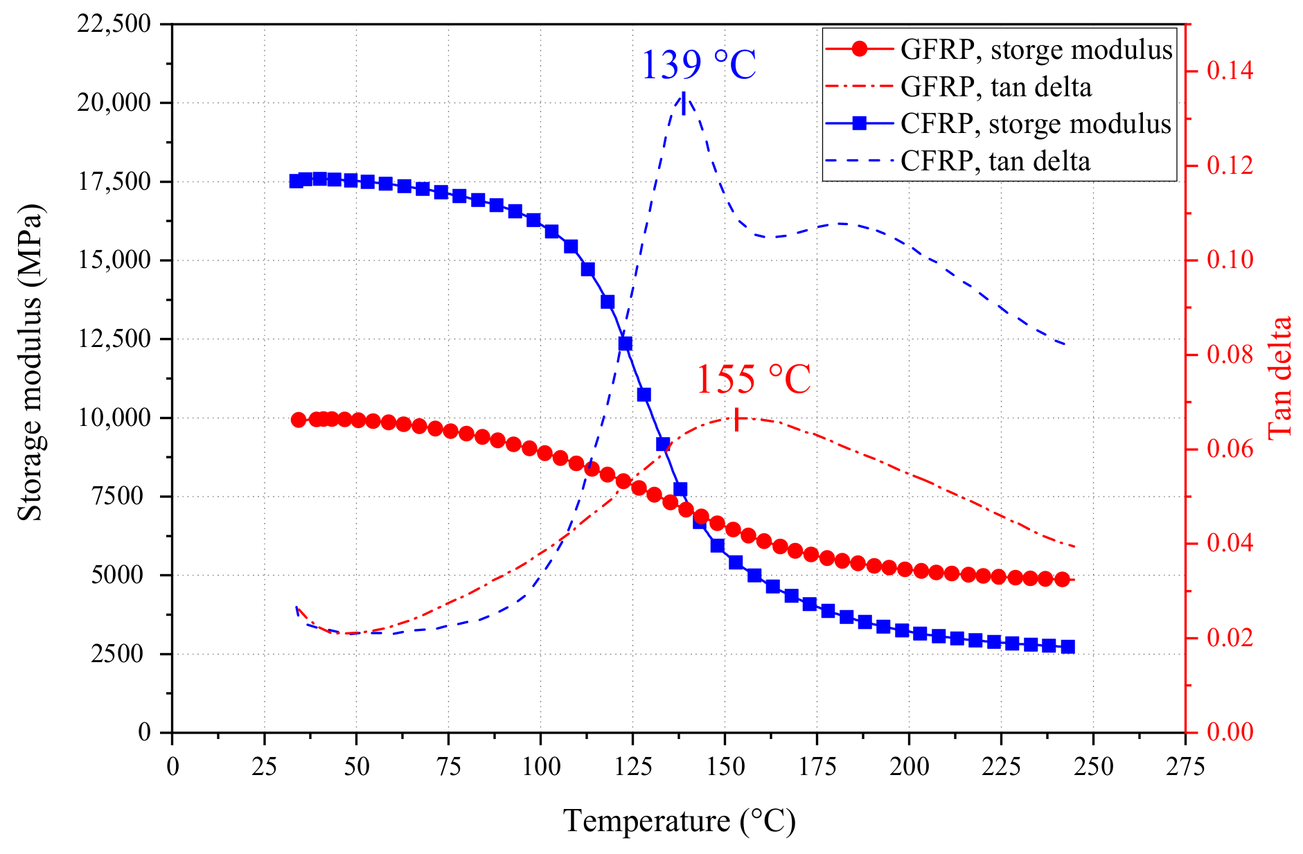
| Glass transition temperature a Tg (°C) | 155 | 139 | |
| Longitudinal coefficient of thermal expansion (×10−6/°C) [40] | 6.0~10.0 | −9.0~0.0 | |
| Transverse coefficient of thermal expansion (×10−6/°C) [40] | 21.0~23.0 | 74.0~104.0 |
| Specimen ID | Cracking Load Pcr (kN) | Cracking Moment Mcr (kN·m) | Maximum Crack Width ωmax (mm) | Failure Mode |
|---|---|---|---|---|
| G-25 | 13.0 | 3.25 | 1.9 | GFRP rupture |
| G-200 | 6.0 | 1.5 | 2 | GFRP rupture |
| G-400 | 4.0 | 1.0 | 2 | GFRP rupture |
| G-600 | 1.0 | 0.25 | 2 | GFRP rupture |
| C-25 | 16.0 | 4.0 | 1.5 | CFRP rupture |
| C-400 | 4.0 | 1.0 | 1.8 | CFRP rupture |
| C-600 | 1.0 | 0.25 | - | Debonding |
| Specimen ID | Ultimate Load Fu (kN) | Ultimate Moment Mu (kN·m) | Ultimate Moment Decreases Amplitude (%) | |
|---|---|---|---|---|
| G-25 | 75 | 18.75 | 1 | - |
| G-200 | 73 | 18.2 | 0.97 | 3 |
| G-400 | 67 | 16.8 | 0.89 | 11 |
| G-600 | 18 | 4.5 | 0.24 | 76 |
| C-25 | 76 | 19.0 | 1 | - |
| C-400 | 73 | 18.25 | 0.96 | 4 |
| C-600 | 2 | 0.5 | 0.03 | 97 |
| Specimen ID | Load (kN) | Measured Value ωexp (mm) | GB 50608-2010 Calculated Value ωmax1 (mm) | Modified Calculated Value ωmax2 (mm) | ||
|---|---|---|---|---|---|---|
| G-25 | 25 | 0.8 | 0.40 | 0.51 | 2.0 | 1.569 |
| G-25 | 30 | 1.0 | 0.67 | 0.84 | 1.493 | 1.190 |
| C-25 | 25 | 0.42 | 0.24 | 0.30 | 1.75 | 1.40 |
| C-25 | 30 | 0.50 | 0.40 | 0.50 | 1.25 | 1.0 |
| Specimen ID | Load (kN) | Measured Value ωexp (mm) | Calculated Value ωmax,T (mm) | |
|---|---|---|---|---|
| G-200 | 32 | 1.30 | 1.25 | 1.04 |
| G-200 | 36 | 1.45 | 1.58 | 0.918 |
| G-400 | 30 | 1.50 | 1.36 | 1.103 |
| G-400 | 35 | 1.70 | 1.88 | 0.904 |
| C-400 | 30 | 0.76 | 0.81 | 0.938 |
| Specimen ID | Load (kN) | Measured Deflection (mm) | Measured Value Bs,exp (×1011·N·mm2) | GB 50608-2010 Calculated Value Bs1 (×1011·N·mm2) | Modified Calculated Value Bs2 (×1011·N·mm2) | ||
|---|---|---|---|---|---|---|---|
| G-25 | 32 | 6.345 | 3.01 | 3.39 | 0.888 | 3.00 | 1.003 |
| G-25 | 40 | 9.148 | 2.62 | 2.90 | 0.901 | 2.58 | 1.014 |
| G-25 | 50 | 12.646 | 2.36 | 2.60 | 0.908 | 2.32 | 1.019 |
| G-25 | 60 | 16.147 | 2.22 | 2.43 | 0.912 | 2.17 | 1.022 |
| C-25 | 30 | 3.870 | 4.64 | 5.96 | 0.779 | 5.31 | 0.874 |
| C-25 | 40 | 6.080 | 3.94 | 4.87 | 0.810 | 4.35 | 0.906 |
| C-25 | 50 | 8.550 | 3.50 | 4.39 | 0.797 | 3.93 | 0.891 |
| C-25 | 60 | 11.270 | 3.19 | 4.11 | 0.776 | 3.69 | 0.864 |
| Specimen ID | Load (kN) | Measured Deflection (mm) | Measured Stiffness Bexp (×1011·N·mm2) | Calculated Value Bs,T (×1011·N·mm2) | |
|---|---|---|---|---|---|
| G-200 | 30 | 9.364 | 1.92 | 1.99 | 0.966 |
| G-200 | 40 | 13.124 | 1.83 | 1.61 | 1.133 |
| G-200 | 50 | 17.054 | 1.76 | 1.45 | 1.213 |
| G-400 | 30 | 12.026 | 1.49 | 1.43 | 1.043 |
| G-400 | 35 | 14.512 | 1.44 | 1.26 | 1.141 |
| G-400 | 40 | 17.478 | 1.37 | 1.16 | 1.181 |
| G-400 | 45 | 22.090 | 1.22 | 1.09 | 1.117 |
| C-400 | 30 | 7.929 | 2.27 | 2.68 | 0.847 |
| C-400 | 40 | 10.670 | 2.25 | 2.20 | 1.023 |
| C-400 | 50 | 13.804 | 2.17 | 1.99 | 1.090 |
| Specimen ID | Calculated Failure Mode | Actual Failure Mode | ||
|---|---|---|---|---|
| G-200 | 27.1 | 20.0 | FRP rupture | FRP rupture |
| G-400 | 33.0 | 17.6 | FRP rupture | FRP rupture |
| C-400 | 48.2 | 18.7 | FRP rupture | FRP rupture |
| Specimen ID | Measured Ultimate Moment Mexp (kN·m) | Calculated Ultimate Moment Mc (kN·m) | |
|---|---|---|---|
| G-200 | 18.2 | 21.4 | 0.850 |
| G-400 | 16.8 | 14.8 | 1.135 |
| C-400 | 18.25 | 15.7 | 1.162 |
Publisher’s Note: MDPI stays neutral with regard to jurisdictional claims in published maps and institutional affiliations. |
© 2022 by the authors. Licensee MDPI, Basel, Switzerland. This article is an open access article distributed under the terms and conditions of the Creative Commons Attribution (CC BY) license (https://creativecommons.org/licenses/by/4.0/).
Share and Cite
Zhao, J.; Pan, H.; Wang, Z.; Li, G. Experimental and Theoretical Study on Flexural Behavior of GFRP- and CFRP-Reinforced Concrete Beams after High-Temperature Exposure. Polymers 2022, 14, 4002. https://doi.org/10.3390/polym14194002
Zhao J, Pan H, Wang Z, Li G. Experimental and Theoretical Study on Flexural Behavior of GFRP- and CFRP-Reinforced Concrete Beams after High-Temperature Exposure. Polymers. 2022; 14(19):4002. https://doi.org/10.3390/polym14194002
Chicago/Turabian StyleZhao, Jun, Haojin Pan, Zike Wang, and Guanghui Li. 2022. "Experimental and Theoretical Study on Flexural Behavior of GFRP- and CFRP-Reinforced Concrete Beams after High-Temperature Exposure" Polymers 14, no. 19: 4002. https://doi.org/10.3390/polym14194002
APA StyleZhao, J., Pan, H., Wang, Z., & Li, G. (2022). Experimental and Theoretical Study on Flexural Behavior of GFRP- and CFRP-Reinforced Concrete Beams after High-Temperature Exposure. Polymers, 14(19), 4002. https://doi.org/10.3390/polym14194002