4.1. Mechanism for the Creation of Surface Morphology
Both carbon-fiber-reinforced PEEK and glass-fiber-reinforced PEEK contained a PEEK matrix and fiber reinforcement, so the formation mechanism of their surface morphology was also determined with the removal mechanism of the two materials.
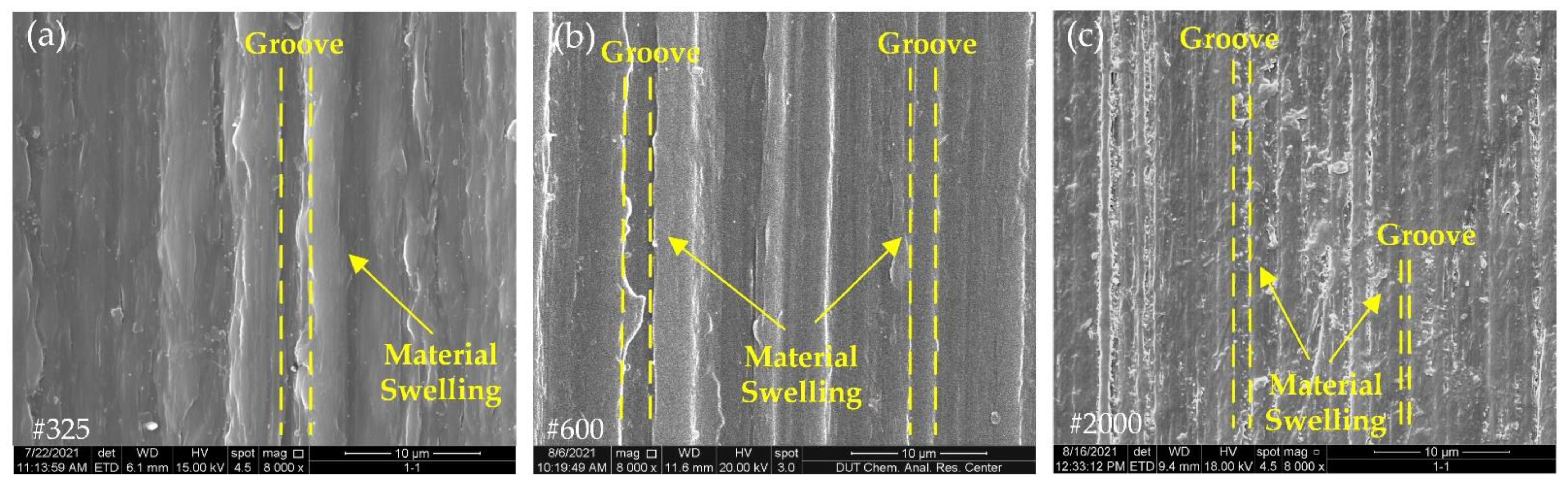
PEEK is a plastic material. During the grinding process, as the grit continued to penetrate into the workpiece surface, the plastic material went through three different stages, namely, friction, plowing and cutting [
23], and, finally, formed chips, and material swelling appeared on both sides of the grinding grooves. In the surface morphology results of the fiber-reinforced PEEK composites in
Figure 7,
Figure 8,
Figure 9 and
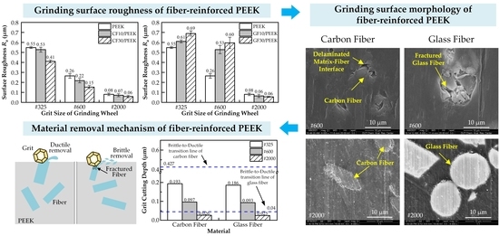
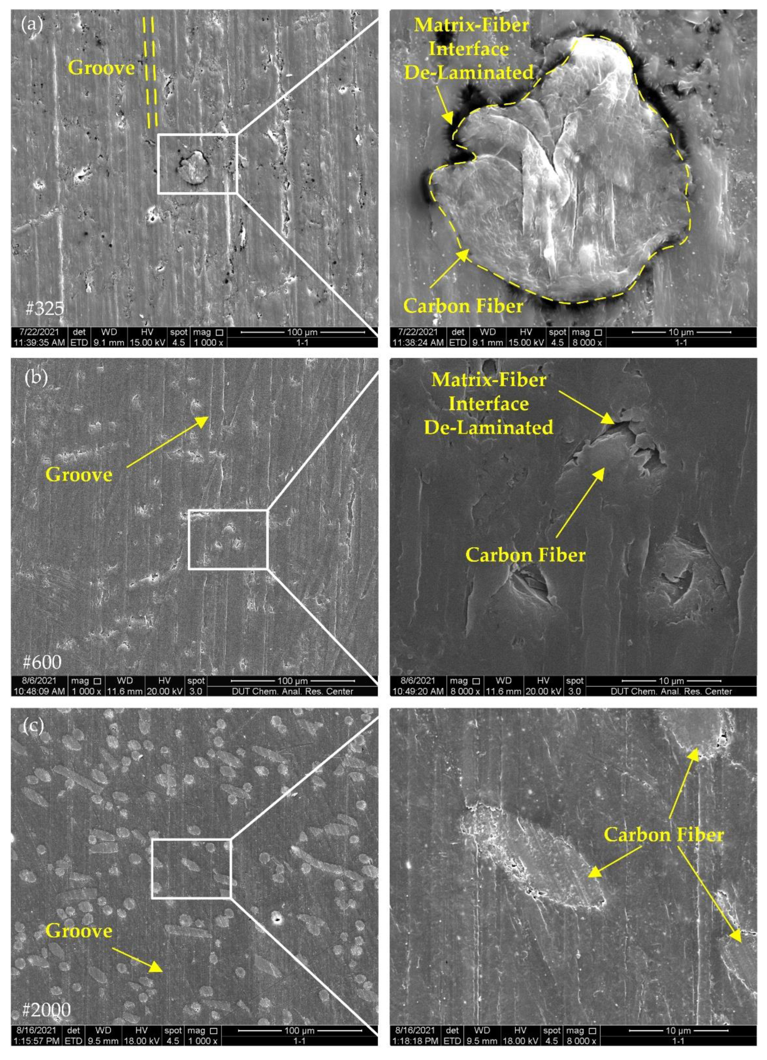
Figure 10, clear grinding grooves could be observed in all PEEK parts, and material swelling appeared on both sides of the grinding grooves, which indicated that the removal mechanism of the PEEK part was ductile removal.
Carbon fiber and glass fiber belong to brittle materials [
24,
25]. The removal mechanism of brittle materials can be divided into brittle removal and ductile removal. When the material is removed with brittle removal, a large number of cracks can appear on the surface of the material; when the material is removed with ductile removal, the surface of the material can show ductile removal marks similar to those of plastic materials [
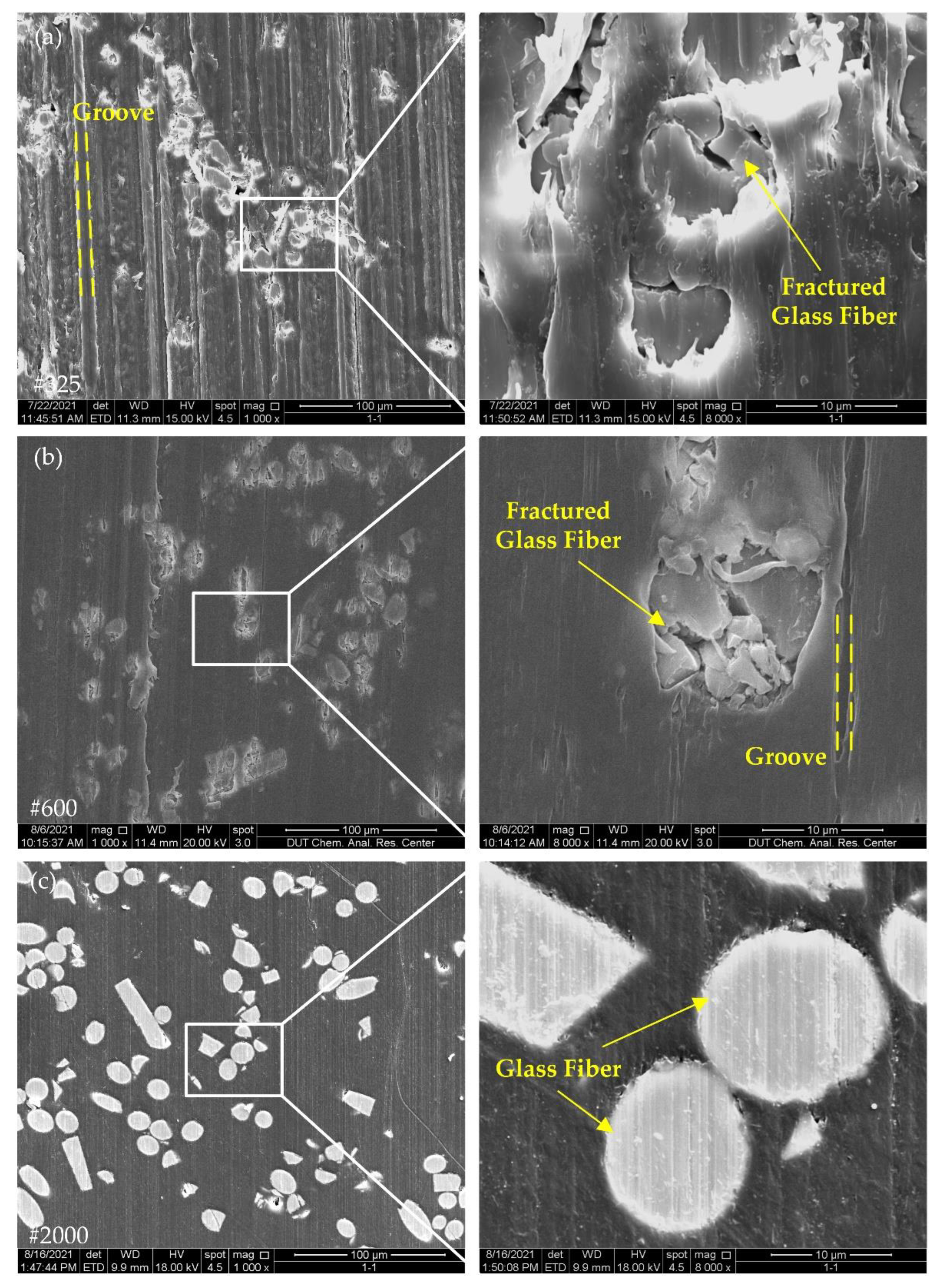
26]. In
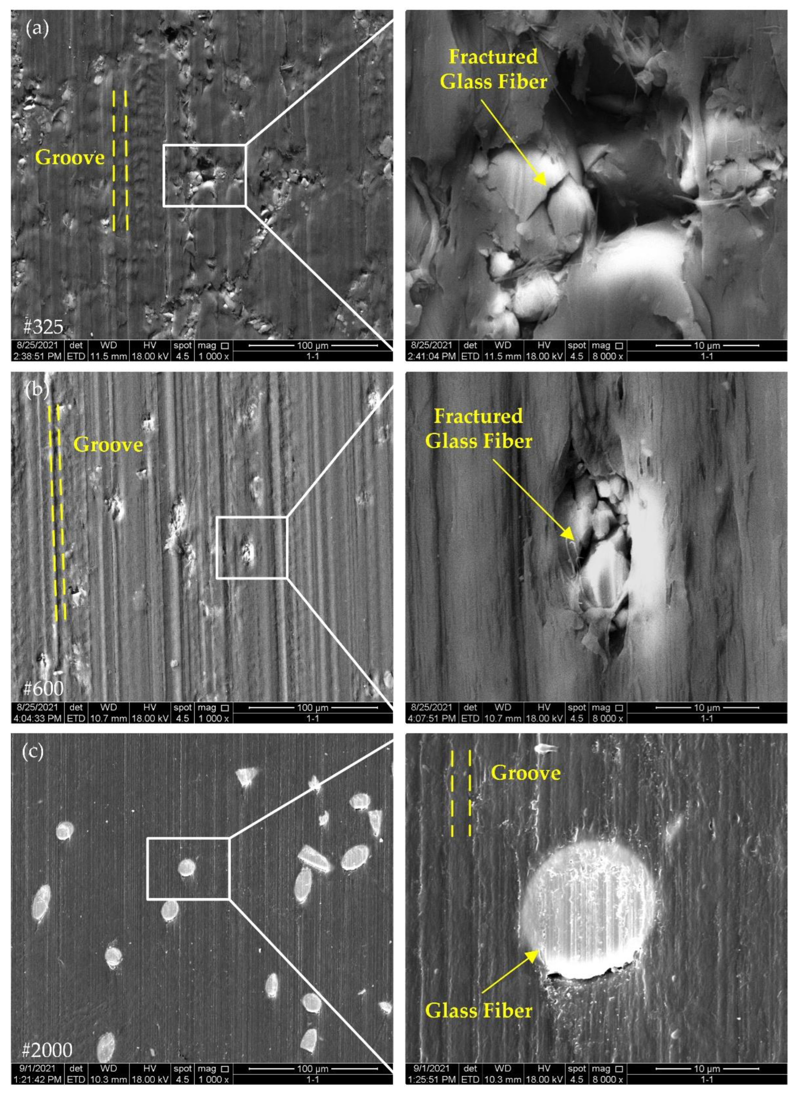
Figure 9 and
Figure 10, the glass fiber surfaces ground with the #325 and #600 grinding wheels showed obvious cracks, while the glass fibers were more intact after grinding with the #2000 grinding wheels. It follows that the removal mechanism of the glass fibers changed with grinding wheels of different grit sizes.
In the study about the removal mechanism of brittle materials, based on the removal energy, Bifano [
27] proposed a classical critical depth of cut model for the brittle–ductile transformation of hard and brittle materials, as shown in Equation (1):
where
β is the integrated coefficient of the model,
E,
H and
Kc are the elastic modulus, hardness and fracture toughness of the material, respectively, and
β = 0.15 and
dc are the critical cutting depths of the brittle–ductile transformation. If the cutting depth was greater than
dc, the material would be removed in a brittle removal region, and if the cutting depth was less than
dc, the material would be removed in a plastic removal region. As a consequence, for grinding, the removal mode of materials can be decided with the cutting depth of the grit.
In a study on the cutting depth of grit, Zhang et al. [
28] proposed a new calculation method for determining the cutting depth of grit for the rotational grinding of workpieces, as shown in Equation (2). The values of various material property parameters required to calculate the critical cutting depth for the brittle–ductile transition of carbon fiber and glass fiber and the parameter values required to calculate the calculation method of the grit cutting depth are shown in
Table 4 and
Table 5, respectively.
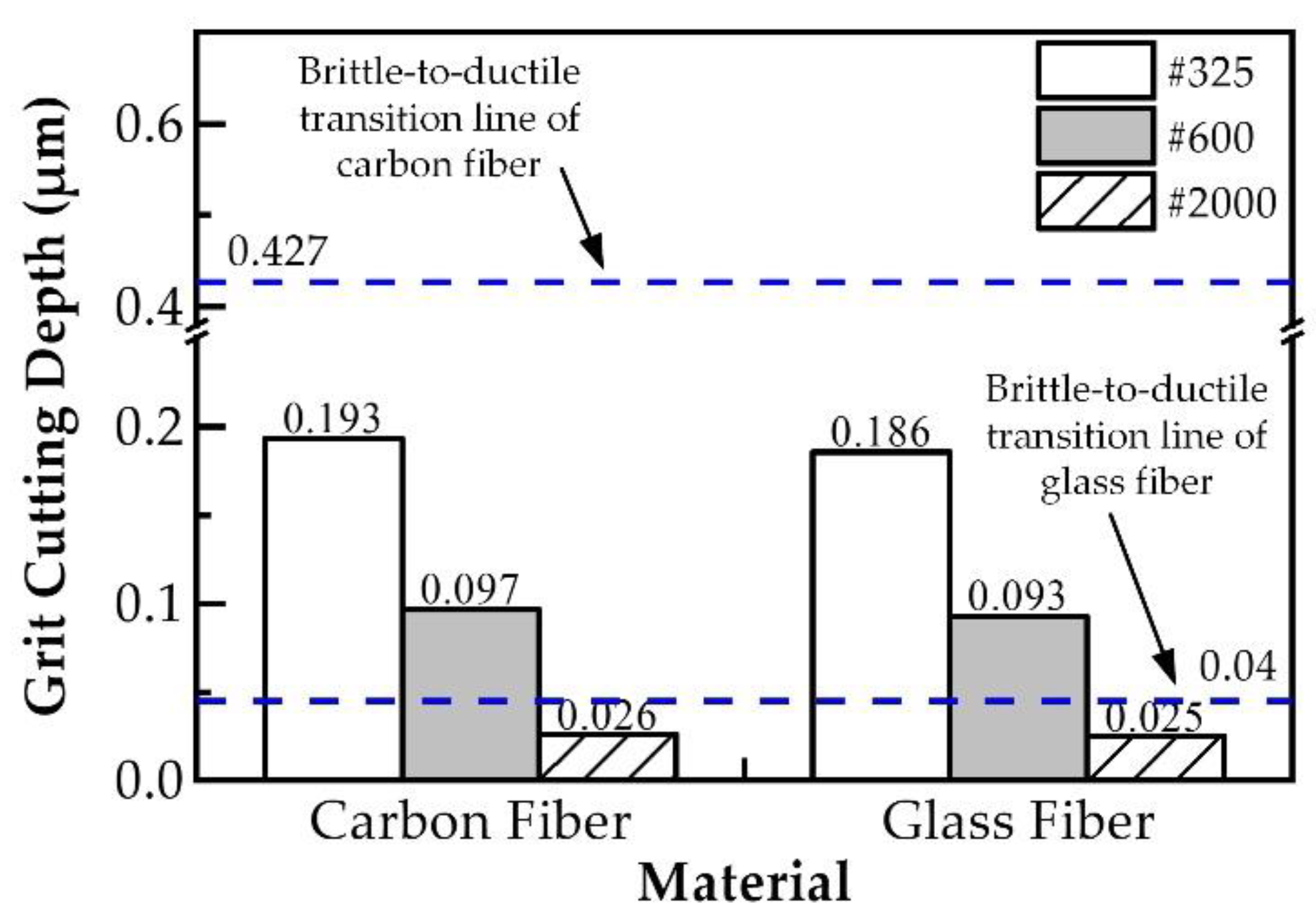
The comparison results between the critical cutting depths of carbon fiber and glass fiber for the brittle–ductile transition and the grit cutting depths of carbon fiber and glass fiber in various grinding wheels are shown in
Figure 11. It is know that the grit cutting depth is less than the brittle–ductile transformation depth of carbon fiber when the carbon fiber is ground with #325, #600 and #2000 wheels, which indicates that carbon fiber is removed in a ductile removal mode. When glass fibers were ground with the #325 and #600 wheels, the grit cutting depth was greater than the brittle–ductile transformation depth of the glass fibers, while the grit cutting depth was less than the brittle–ductile transformation depth of glass fibers when the glass fiber was ground with the #2000 wheels. This conclusion suggests that glass fibers were removed in a brittle removal mode when ground with the #325 and #600 wheels, and in a ductile removal mode when ground with the #2000 wheels.
The damage at the fiber–matrix interface was also one of the basic surface damages of the composite material. As can be seen from the surface morphology of the fiber-reinforced PEEK composites in
Figure 7,
Figure 8,
Figure 9 and
Figure 10, after grinding with #325 and #600 grinding wheels, fiber–matrix interface de-bonding was observed on either CF/PEEK or GF/PEEK surfaces, but after grinding with the #2000 grinding wheel, the interface de-bonding between the fiber and matrix obviously improved. During grinding, stress concentration may occur at the fiber–matrix interface. When stress exceeds the maximum bonding force provided by the fiber and matrix, the fiber–matrix interface can be damaged and de-bonding can occur. Due to the internal abrasive grit size of the #2000 grinding wheel being small, the radius of the grit was only 3.25 μm, and the number of grits per unit area of grinding wheel surface was large. As a result, the grinding force applied on individual grit was reduced, the grinding force at the fiber–matrix interface was also reduced and the grinding force provided by the individual grit did not exceed the bonding force between the fiber and matrix. This may be the reason why no obvious de-bonding phenomenon was observed on the material surface after grinding with the #2000 grinding wheel.
4.2. Surface Roughness Analysis for Grinding Processing
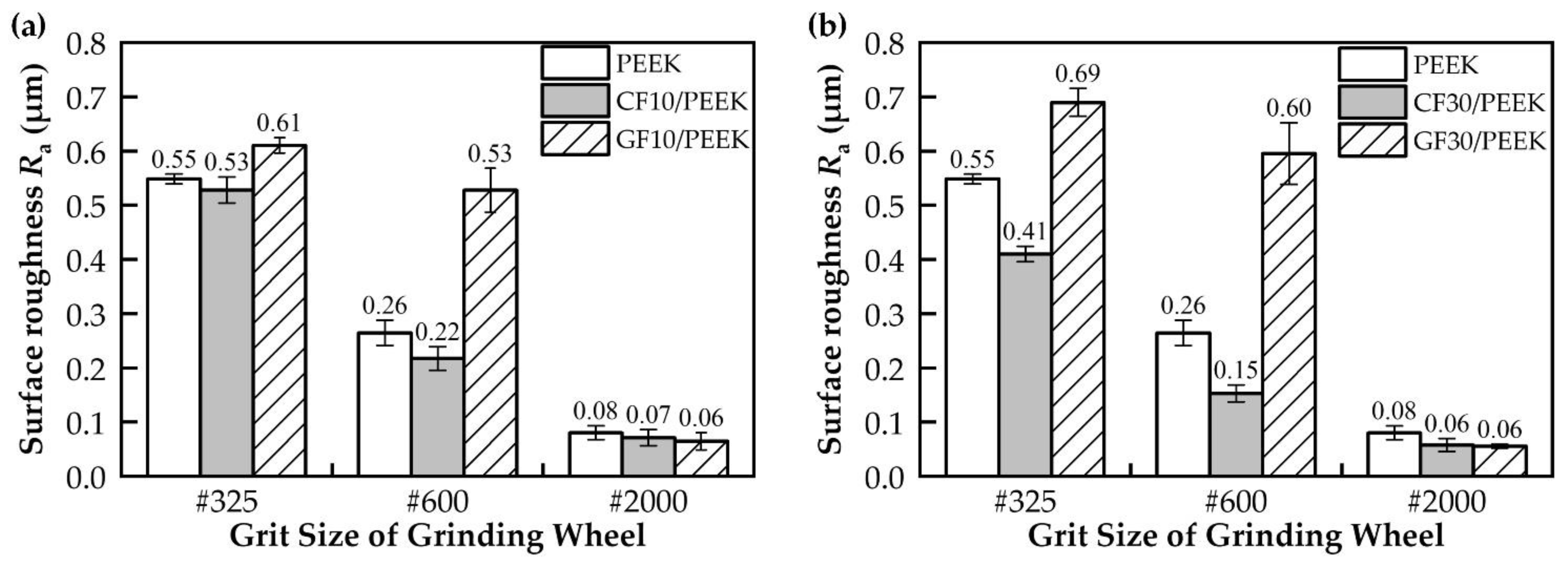
As shown in
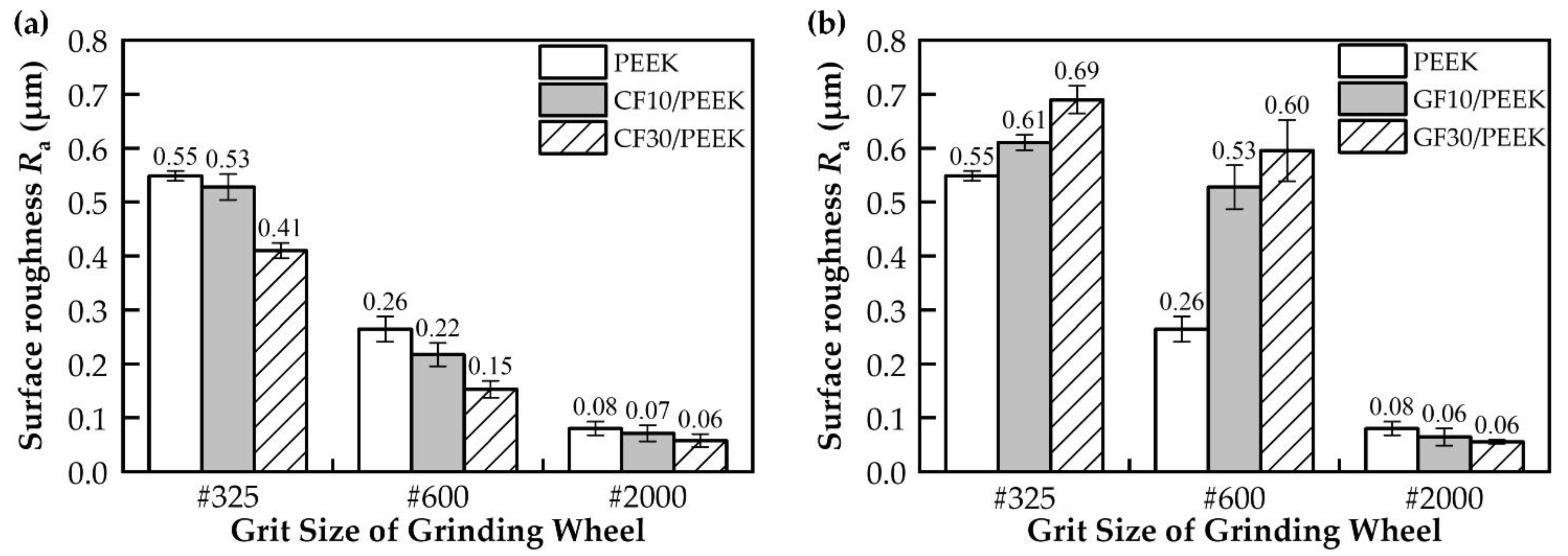
Figure 4a, the addition of carbon fibers to PEEK effectively reduced the surface roughness of the material, and the higher the fiber mass fraction, the lower the surface roughness. In general, the physical properties of the material affected the amount of the deformation of the surface material during grinding, and the material with high plasticity swelled more on both sides of the grooves than the material with weak plasticity. On the one hand, adding carbon fibers to PEEK could increase the crystallinity of the PEEK matrix [
34], and as the crystallinity of PEEK increased, the tensile strength of PEEK and the modulus would increase and the plasticity capacity would weaken [
35]. Therefore, adding carbon fibers could effectively reduce the degree of material swelling on both sides of the PEEK matrix grooves and improve the grinding surface quality. On the other hand, the CF30/PEEK’s nano-indentation curve was higher than CF10/PEEK [
21], indicating that CF30/PEEK had a better deformation resistance. As seen in
Figure 7 and
Figure 8, the grooves on the surface of CF30/PEEK were shallower than those on CF10/PEEK after grinding with the same grit size grinding wheel.
The grooves on the grinding surface were formed by countless grits scratching the workpiece’s surface, and the average cut depth of grit was proportional to the material surface roughness after grinding. The value
k in Equation (2) is the effective grit number that had a cutting effect on the surface layer of the grinding wheel in the grinding process, where the value
k ranged from 0 to 0.5 [
36]. The number of effective grits is influenced by the minimum chip thickness of the material, which is influenced by the ratio of the elastic modulus to the tensile strength of the material [
37]. The larger the minimum cutting thickness of the material, the less effective grits can be cut on the surface layer of the grinding wheel.
It is worth noting that the value of
k was empirical and could not be determined precisely; the general value for brittle materials is 0.2. However, both CF30/PEEK and GF30/PEEK were weak plastic materials. Thus, based on the tensile test results of Gao et al. [
21], this paper sorted the minimum cutting thickness values of different materials by calculating the ratio of the elastic modulus to tensile strength and divided the value of
k into five different values corresponding to five different materials in the test.
Table 6 shows the value results.
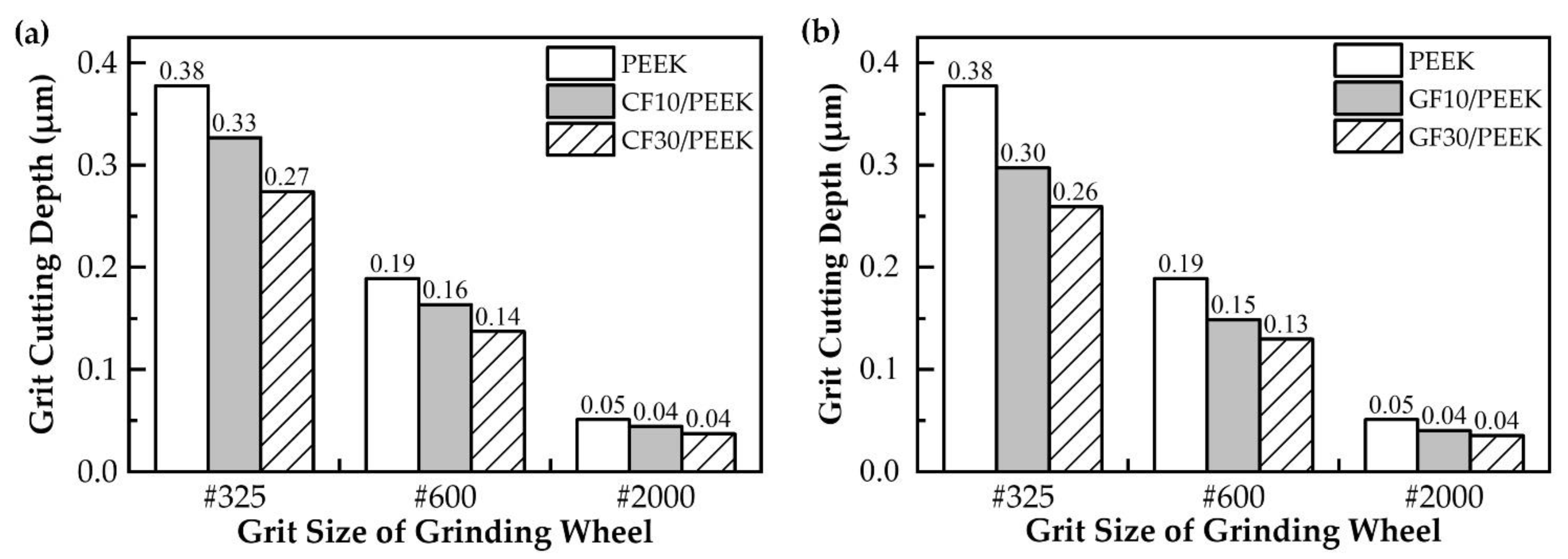
The results of the grit cutting depth of different materials are shown in
Figure 12. With the increase in the grit size of the mesh, the surface roughness was reduced due to the reduction in the grit cutting depth. In
Figure 12a, CF30/PEEK had a smaller grit cutting depth than CF10/PEEK, so CF30/PEEK had less surface roughness than CF10/PEEK. In
Figure 12b, although GF30/PEEK had a smaller grit cutting depth than GF10/PEEK, the glass fibers were removed in the brittle mode when grinding with the #325 and #600 wheels, and the broken glass fibers were distributed on the surface of the material, which deteriorated the surface quality, so GF30/PEEK had a larger surface roughness than GF10/PEEK.


