Effect of Fiber Type and Content on Surface Quality and Removal Mechanism of Fiber-Reinforced Polyetheretherketone in Ultra-Precision Grinding
Abstract
:1. Introduction
2. Materials and Methods
2.1. Materials
2.2. Methods
3. Results
3.1. Surface Roughness of Pure PEEK and Fiber-Reinforced PEEK
3.2. Surface Morphology of Pure PEEK and Fiber-Reinforced PEEK
4. Discussion
4.1. Mechanism for the Creation of Surface Morphology
4.2. Surface Roughness Analysis for Grinding Processing
5. Conclusions
Author Contributions
Funding
Institutional Review Board Statement
Informed Consent Statement
Data Availability Statement
Acknowledgments
Conflicts of Interest
References
- Panayotov, I.V.; Orti, V.; Cuisinier, F.; Yachouh, J. Polyetheretherketone (PEEK) for medical applications. J. Mater. Sci. Mater. Med. 2016, 27, 118. [Google Scholar] [CrossRef] [PubMed]
- Kalra, S.; Munjal, B.S.; Singh, V.R.; Mahajan, M.; Bhattacharya, B. Investigations on the suitability of PEEK material under space environment conditions and its application in a parabolic space antenna. Adv. Space Res. 2019, 63, 4039–4045. [Google Scholar] [CrossRef]
- Ling, X.; Jing, X.; Zhang, C.; Chen, S. Polyether Ether Ketone (PEEK) Properties and Its Application Status. IOP Conf. Ser. Earth Environ. Sci. 2020, 453, 12080. [Google Scholar] [CrossRef]
- Geng, Y.; Ren, D.; Li, S.; Li, Z.; Shen, X.; Yuan, Y. Hydroxyapatite-incorporation improves bone formation on endosseous PEEK implant in canine tibia. J. Appl. Biomater. Funct. Mater. 2020, 18, 58810733. [Google Scholar] [CrossRef] [PubMed]
- Torstrick, F.B.; Lin, A.S.P.; Potter, D.; Safranski, D.L.; Sulchek, T.A.; Gall, K.; Guldberg, R.E. Porous PEEK improves the bone-implant interface compared to plasma-sprayed titanium coating on PEEK. Biomaterials 2018, 185, 106–116. [Google Scholar] [CrossRef] [PubMed]
- Mahmoud Zaghloul, M.Y.; Yousry Zaghloul, M.M.; Yousry Zaghloul, M.M. Developments in polyester composite materials—An in-depth review on natural fibres and nano fillers. Compos. Struct. 2021, 278, 114698. [Google Scholar] [CrossRef]
- Gümüş, M.; Arslan, A. Effect of fiber type and content on the flexural behavior of high strength concrete beams with low reinforcement ratios. Structures 2019, 20, 1–10. [Google Scholar] [CrossRef]
- Nassar, R.; Soroushian, P.; Balachandra, A.; Nassar, S.; Weerasiri, R.; Darsanasiri, N.; Abdol, N. Effect of fiber type and content on the performance of extruded wood fiber cement products. Case Stud. Constr. Mater. 2022, 16, e968. [Google Scholar] [CrossRef]
- Zaghloul, M.M.Y.; Zaghloul, M.Y.M.; Zaghloul, M.M.Y. Experimental and modeling analysis of mechanical-electrical behaviors of polypropylene composites filled with graphite and MWCNT fillers. Polym. Test. 2017, 63, 467–474. [Google Scholar] [CrossRef]
- Fuseini, M.; Zaghloul, M.M.Y. Investigation of Electrophoretic Deposition of PANI Nano fibers as a Manufacturing Technology for corrosion protection. Prog. Org. Coat. 2022, 171, 107015. [Google Scholar] [CrossRef]
- Zaghloul, M.M.Y.M. Mechanical properties of linear low-density polyethylene fire-retarded with melamine polyphosphate. J. Appl. Polym. Sci. 2018, 135, 46770. [Google Scholar] [CrossRef]
- Alshammari, B.A.; Alsuhybani, M.S.; Almushaikeh, A.M.; Alotaibi, B.M.; Alenad, A.M.; Alqahtani, N.B.; Alharbi, A.G. Comprehensive Review of the Properties and Modifications of Carbon Fiber-Reinforced Thermoplastic Composites. Polymers 2021, 13, 2474. [Google Scholar] [CrossRef]
- Sathishkumar, T.P.; Satheeshkumar, S.; Naveen, J. Glass fiber-reinforced polymer composites—A review. J. Reinf. Plast. Compos. 2014, 33, 1258–1275. [Google Scholar] [CrossRef]
- Sarasua, J.; Remiro, P.; Pouyet, J. The mechanical behaviour of PEEK short fibre composites. J. Mater. Sci. 1995, 30, 3501–3508. [Google Scholar] [CrossRef]
- Davim, J.P.; Cardoso, R. Effect of the reinforcement (carbon or glass fibres) on friction and wear behaviour of the PEEK against steel surface at long dry sliding. Wear 2009, 266, 795–799. [Google Scholar] [CrossRef]
- Ji, S.; Yu, H.; Zhao, J.; Liang, F. Comparison of mechanical property and machinability for polyetheretherketone and glass fiber-reinforced polyetheretherketone. Adv. Mech. Eng. 2015, 7, 757567243. [Google Scholar] [CrossRef] [Green Version]
- Paulo Davim, J.; Reis, P.; Lapa, V.; Conceição António, C. Machinability study on polyetheretherketone (PEEK) unreinforced and reinforced (GF30) for applications in structural components. Compos. Struct. 2003, 62, 67–73. [Google Scholar] [CrossRef]
- Yan, Y.; Mao, Y.; Li, B.; Zhou, P. Machinability of the Thermoplastic Polymers: PEEK, PI, and PMMA. Polymers 2020, 13, 69. [Google Scholar] [CrossRef]
- Khoran, M.; Amirabadi, H.; Azarhoushang, B. The effects of cryogenic cooling on the grinding process of polyether ether ketone (PEEK). J. Manuf. Process. 2020, 56, 1075–1087. [Google Scholar] [CrossRef]
- Khoran, M.; Azarhoushang, B.; Amirabadi, H. Evaluating the influence of reinforcing fiber type on the grinding process of PEEK’s composites. Int. J. Adv. Manuf. Technol. 2022, 119, 2187–2200. [Google Scholar] [CrossRef]
- Gao, S.; Qu, J.; Li, H.; Kang, R. Effect of Fiber Type and Content on Mechanical Property and Lapping Machinability of Fiber-Reinforced Polyetheretherketone. Polymers 2022, 14, 1079. [Google Scholar] [CrossRef]
- Datasheet_SustaPEEK__EN. Polyether-Ether-Ketone Material Properties. 2016. Available online: https://www.roechling.com/industrial/ (accessed on 20 April 2022).
- Hokkirigawa, K.; Kato, K. An experimental and theoretical investigation of ploughing, cutting and wedge formation during abrasive wear. Tribol. Int. 1988, 21, 51–57. [Google Scholar] [CrossRef]
- Newcomb, B.A. Processing, structure, and properties of carbon fibers. Compos. Part A Appl. Sci. Manuf. 2016, 91, 262–282. [Google Scholar] [CrossRef]
- Sharma, V.; Meena, M.L.; Kumar, M.; Kumar, G.C.M.; Doddamani, M.R. Mechanical properties of unfilled and particulate filled glass fiber reinforced polymer composites—A review. AIP Conf. Proc. 2019, 2057, 20037. [Google Scholar] [CrossRef]
- Neo, W.K.; Kumar, A.S.; Rahman, M. A review on the current research trends in ductile regime machining. Int. J. Adv. Manuf. Technol. 2012, 63, 465–480. [Google Scholar] [CrossRef]
- Bifano, T.G.; Dow, T.A.; Scattergood, R.O. Ductile-Regime Grinding: A New Technology for Machining Brittle Materials. J. Eng. Ind. 1991, 113, 184–189. [Google Scholar] [CrossRef]
- Zhang, Y.; Kang, R.; Gao, S.; Huang, J.; Zhu, X. A new model of grit cutting depth in wafer rotational grinding considering the effect of the grinding wheel, workpiece characteristics, and grinding parameters. Precis. Eng. 2021, 72, 461–468. [Google Scholar] [CrossRef]
- Qin, X.; Wu, X.; Li, H.; Li, S.; Zhang, S.; Jin, Y. Numerical and experimental investigation of orthogonal cutting of carbon fiber-reinforced polyetheretherketone (CF/PEEK). Int. J. Adv. Manuf. Technol. 2022, 119, 1003–1017. [Google Scholar] [CrossRef]
- Zhang, D.; Li, X.; Xia, H.; Feng, Z.; Zhao, G. Characterization of Elastic Modulus and Hardness of T800 Carbon Fiber Via Nanoindentation Technique. Aerosp. Mater. Technol. 2017, 47, 79–85. [Google Scholar] [CrossRef]
- Wu, Y.; Zhang, B.; Zhang, W. Experimental research of carbon fiber filament’s fracture toughness based on focus iron beam. Acta Mater. Compos. Sin. 2012, 29, 228–232. [Google Scholar] [CrossRef]
- Li, X.; Bhushan, B.; McGinnis, P.B. Nanoscale mechanical characterization of glass fibers. Mater. Lett. 1996, 29, 215–220. [Google Scholar] [CrossRef]
- AU Seal, A.; Chakraborti, P.; Roy, N.; Mukherjee, S.; Mitra, M.; Pas, G. Effect of phase separation on the fracture toughness of SiO2-B2O3-Na2O glass. Bullet. Mater. Sci. 2005, 28, 457–460. [Google Scholar] [CrossRef]
- Wang, P.; Lin, Q.; Wang, Y.; Liu, C.; Shen, C. Comparative study of the crystallization behavior and morphologies of carbon and glass fiber reinforced poly(ether ether ketone) composites. Polym. Polym. Compos. 2021, 29, 1229–1239. [Google Scholar] [CrossRef]
- Yang, C.; Tian, X.; Li, D.; Cao, Y.; Zhao, F.; Shi, C. Influence of thermal processing conditions in 3D printing on the crystallinity and mechanical properties of PEEK material. J. Mater. Process. Technol. 2017, 248, 1–7. [Google Scholar] [CrossRef]
- Lin, B.; Zhou, P.; Wang, Z.; Yan, Y.; Kang, R.; Guo, D. Analytical Elastic–Plastic Cutting Model for Predicting Grain Depth-of-Cut in Ultrafine Grinding of Silicon Wafer. J. Manuf. Sci. Eng. 2018, 140, 121001. [Google Scholar] [CrossRef]
- Setti, D.; Kirsch, B.; Aurich, J.C. An Analytical Method for Prediction of Material Deformation Behavior in Grinding Using Single Grit Analogy. Procedia CIRP 2017, 58, 263–268. [Google Scholar] [CrossRef]




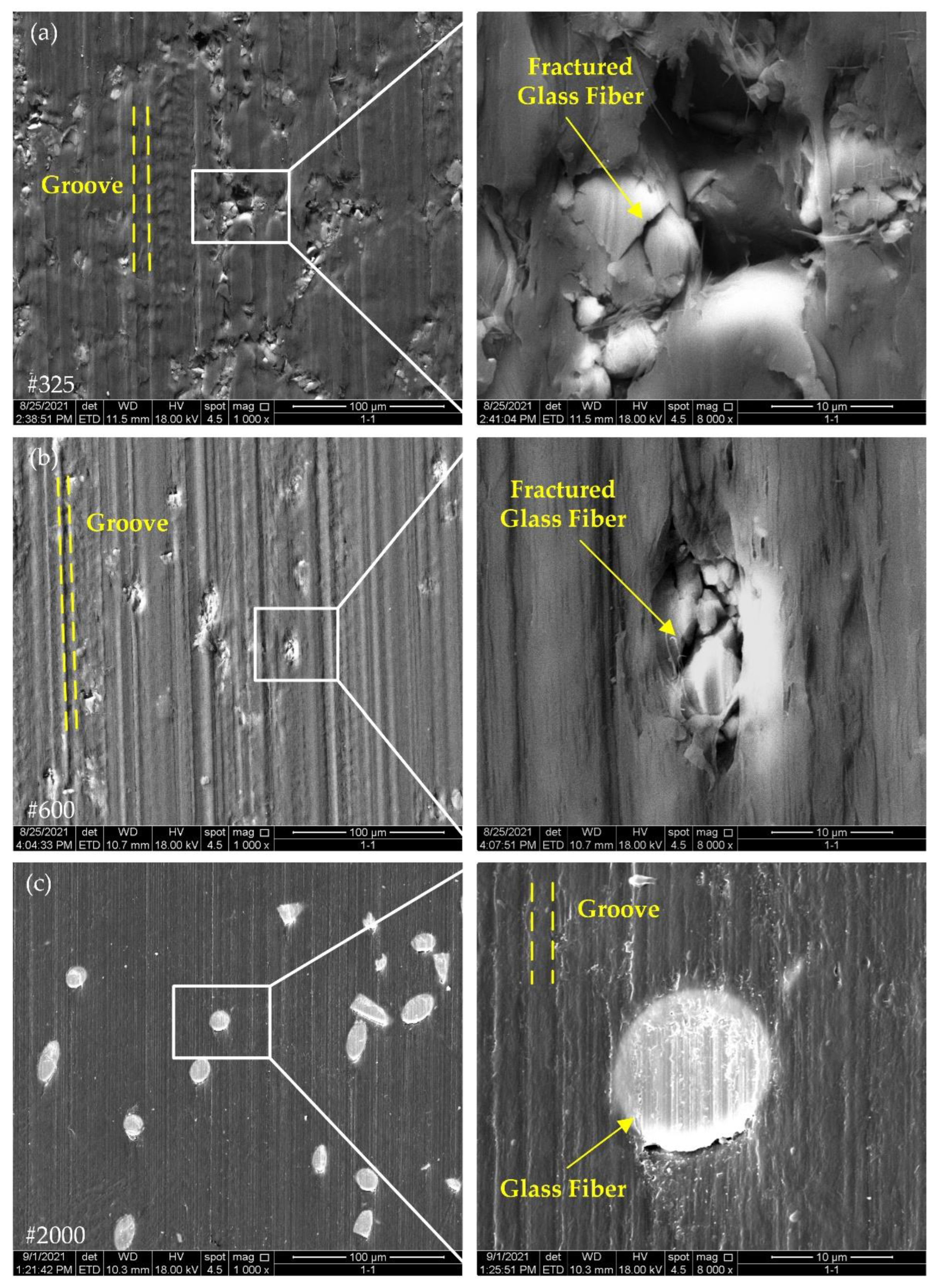
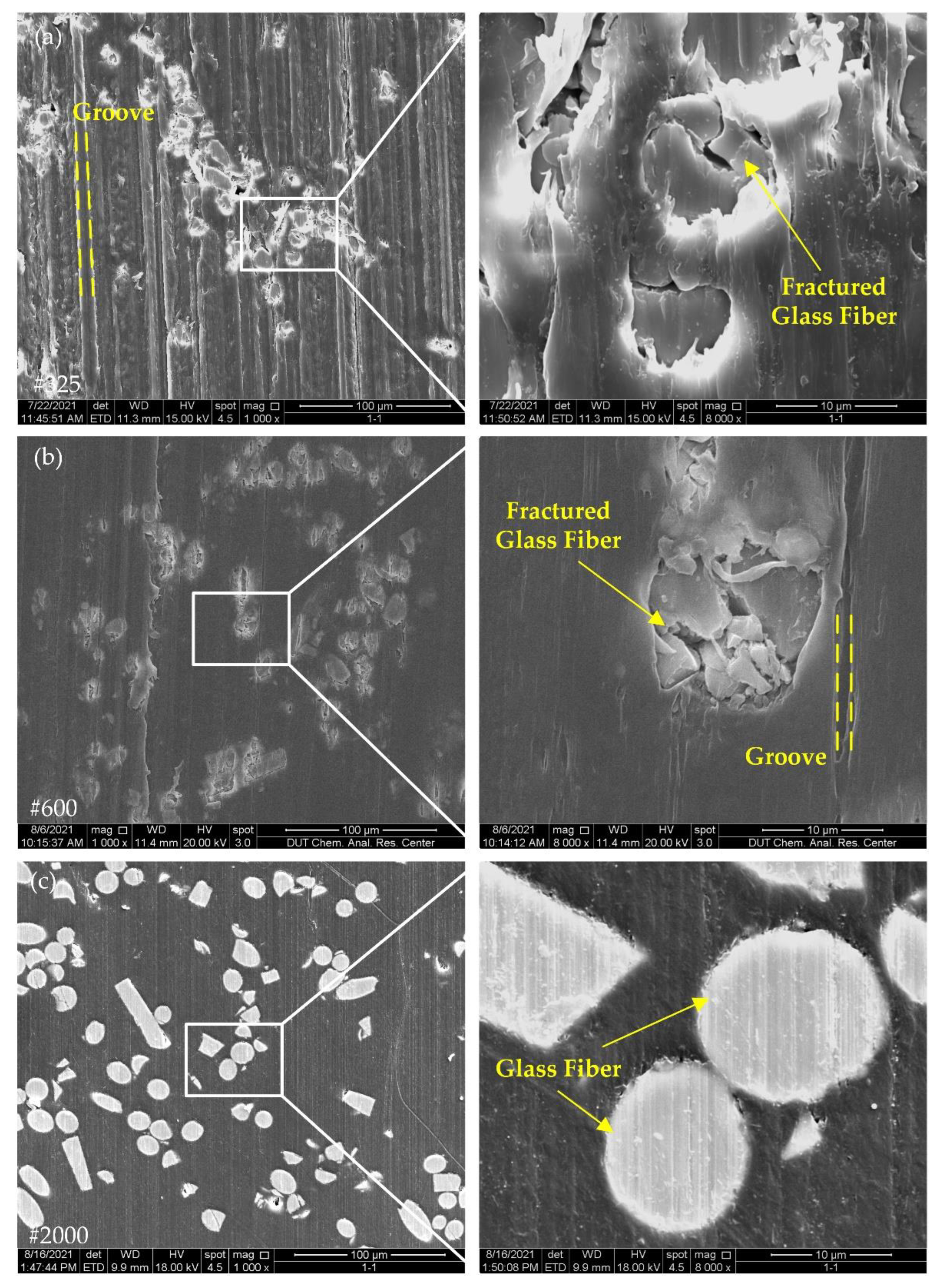
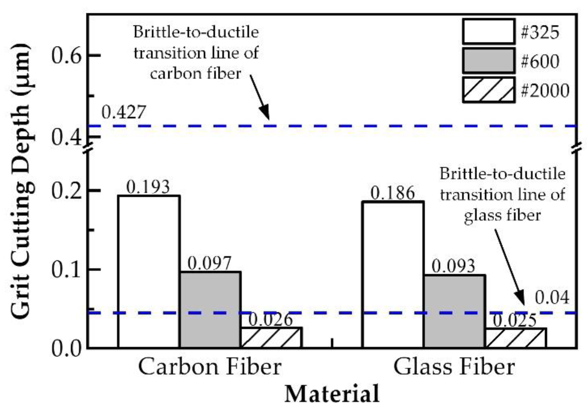
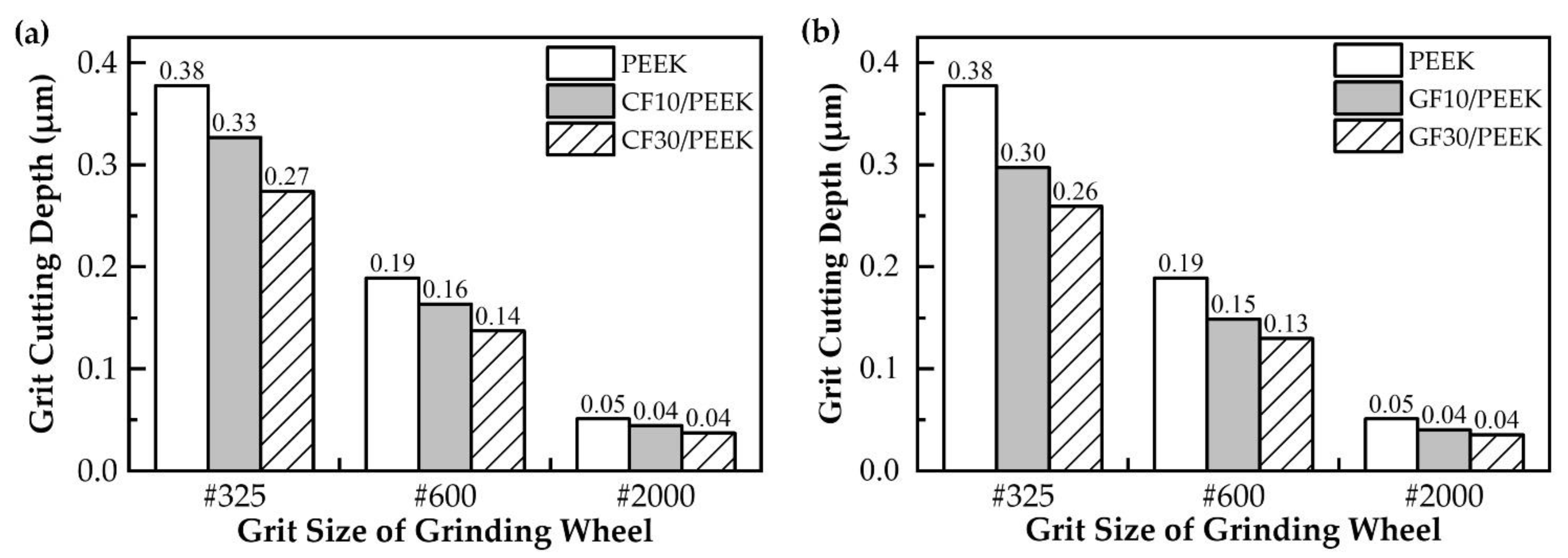
| Parameters | PEEK | CF10/PEEK | CF30/PEEK | GF10/PEEK | GF30/PEEK |
|---|---|---|---|---|---|
| Density (g/cm3) | 1.31 | 1.34 | 1.40 | 1.38 | 1.51 |
| Elastic modulus (MPa) | 5100 | 7050 | 8190 | 5770 | 7330 |
| Yield stress (MPa) | 98.1 | 99.5 | 102.6 | 78.6 | 61.0 |
| Hardness (MPa) | 300 | 370 | 430 | 360 | 380 |
| Elongation at break | 20% | 14% | 7% | 12% | 5% |
| Grinding Condition | Value |
|---|---|
| Type of grinding wheel | Resin-bonded diamond grinding wheel |
| Grit size of grinding wheel | #325 |
| Grinding wheel speed ns (r/min) | 2399, 2099, 1799 |
| Wheel feed rate f (μm/min) | 10, 15, 20 |
| Rotary table speed nw (r/min) | 120, 180, 240 |
| Material removal amount (μm) | 100 |
| Grinding Condition | Value |
|---|---|
| Type of grinding wheel | Resin-bonded diamond grinding wheel |
| Grit size of grinding wheel | #325, #600, #2000 |
| Grinding wheel speed ns (r/min) | 2399 |
| Wheel feed rate f (μm/min) | 10 |
| Rotary table speed nw (r/min) | 120 |
| Material removal amount (μm) | 100 |
| Parameters | Carbon Fiber | Glass Fiber |
|---|---|---|
| Modulus (GPa) | 235 | 72.3 |
| Hardness (GPa) | 5.24 | 7.3 |
| Fracture toughness (MPa·m1/2) | 1.32 | 1.18 |
| Parameters | Value |
|---|---|
| rg (μm) | 24 (#325), 12 (#600), 3.25 (#2000) |
| R1 (μm) | 66,530 |
| nw (r/min) | 120 |
| f (μm/min) | 10 |
| θ | 38° |
| ns (r/min) | 2399 |
| k | 0.2 |
| η | 0.25 |
| W (μm) | 3000 |
| D (μm) | 350,000 |
| Et* (GPa) | 43.956 |
| Materials | k Value |
|---|---|
| PEEK | 0.05 |
| CF10/PEEK | 0.075 |
| CF30/PEEK | 0.125 |
| GF10/PEEK | 0.1 |
| GF30/PEEK | 0.15 |
Publisher’s Note: MDPI stays neutral with regard to jurisdictional claims in published maps and institutional affiliations. |
© 2022 by the authors. Licensee MDPI, Basel, Switzerland. This article is an open access article distributed under the terms and conditions of the Creative Commons Attribution (CC BY) license (https://creativecommons.org/licenses/by/4.0/).
Share and Cite
Gao, S.; Zhou, X.; Guo, J.; Kang, R. Effect of Fiber Type and Content on Surface Quality and Removal Mechanism of Fiber-Reinforced Polyetheretherketone in Ultra-Precision Grinding. Polymers 2022, 14, 4223. https://doi.org/10.3390/polym14194223
Gao S, Zhou X, Guo J, Kang R. Effect of Fiber Type and Content on Surface Quality and Removal Mechanism of Fiber-Reinforced Polyetheretherketone in Ultra-Precision Grinding. Polymers. 2022; 14(19):4223. https://doi.org/10.3390/polym14194223
Chicago/Turabian StyleGao, Shang, Xinyu Zhou, Jiani Guo, and Renke Kang. 2022. "Effect of Fiber Type and Content on Surface Quality and Removal Mechanism of Fiber-Reinforced Polyetheretherketone in Ultra-Precision Grinding" Polymers 14, no. 19: 4223. https://doi.org/10.3390/polym14194223
APA StyleGao, S., Zhou, X., Guo, J., & Kang, R. (2022). Effect of Fiber Type and Content on Surface Quality and Removal Mechanism of Fiber-Reinforced Polyetheretherketone in Ultra-Precision Grinding. Polymers, 14(19), 4223. https://doi.org/10.3390/polym14194223


