

Inkjet Printing of Electrodes on Electrospun Micro- and Nanofiber Hydrophobic Membranes for Flexible and Smart Textile Applications

Abstract
:1. Introduction
2. Materials and Methods
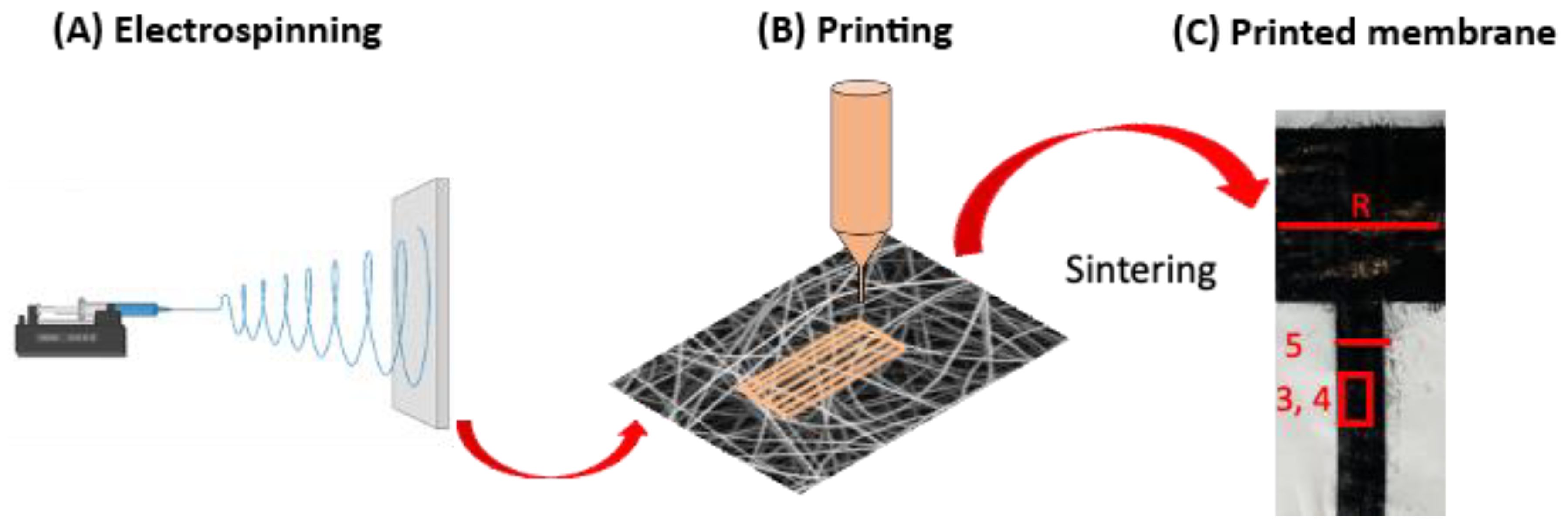
2.1. Electrospinning
2.2. Inkjet Printing and Sintering
2.3. Characterization of Printed Layers on Electrospun Membranes
2.4. Indirect Cytotoxicity Test
3. Results and Discussion
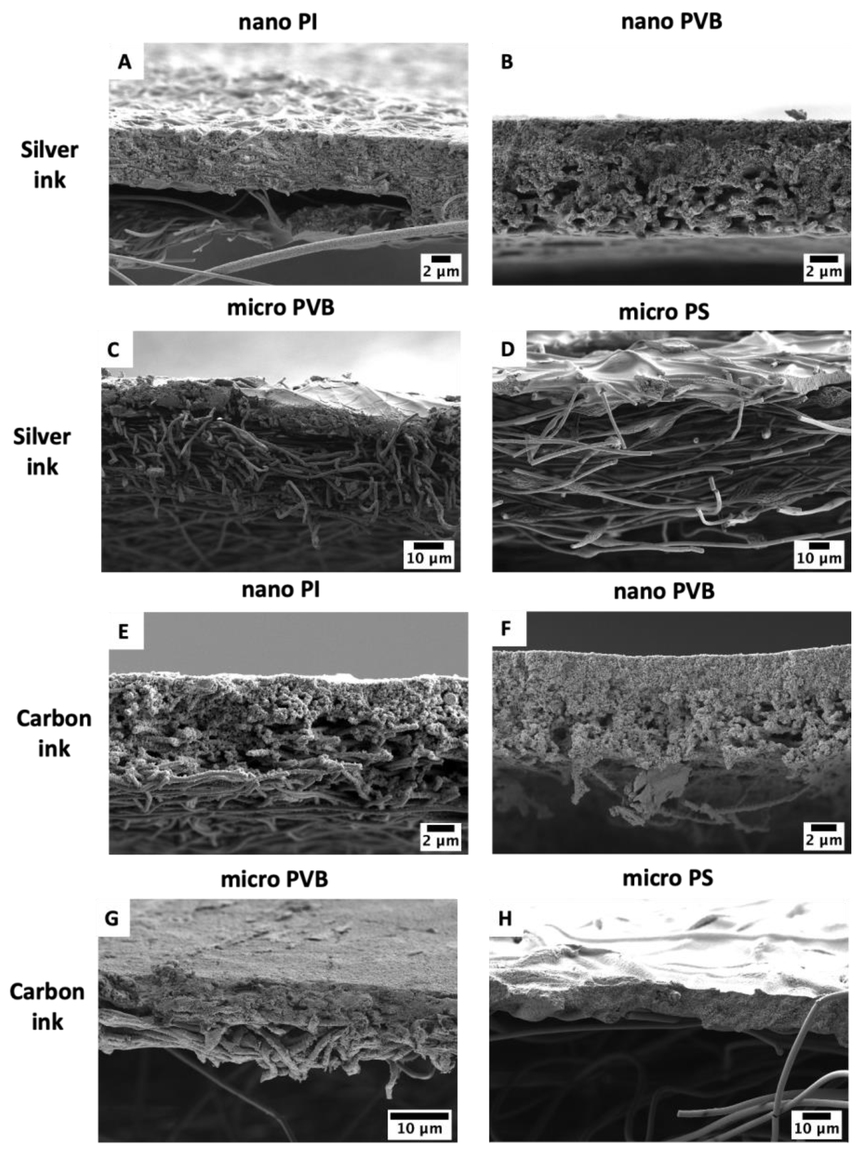
3.1. Printability
3.2. Resistance
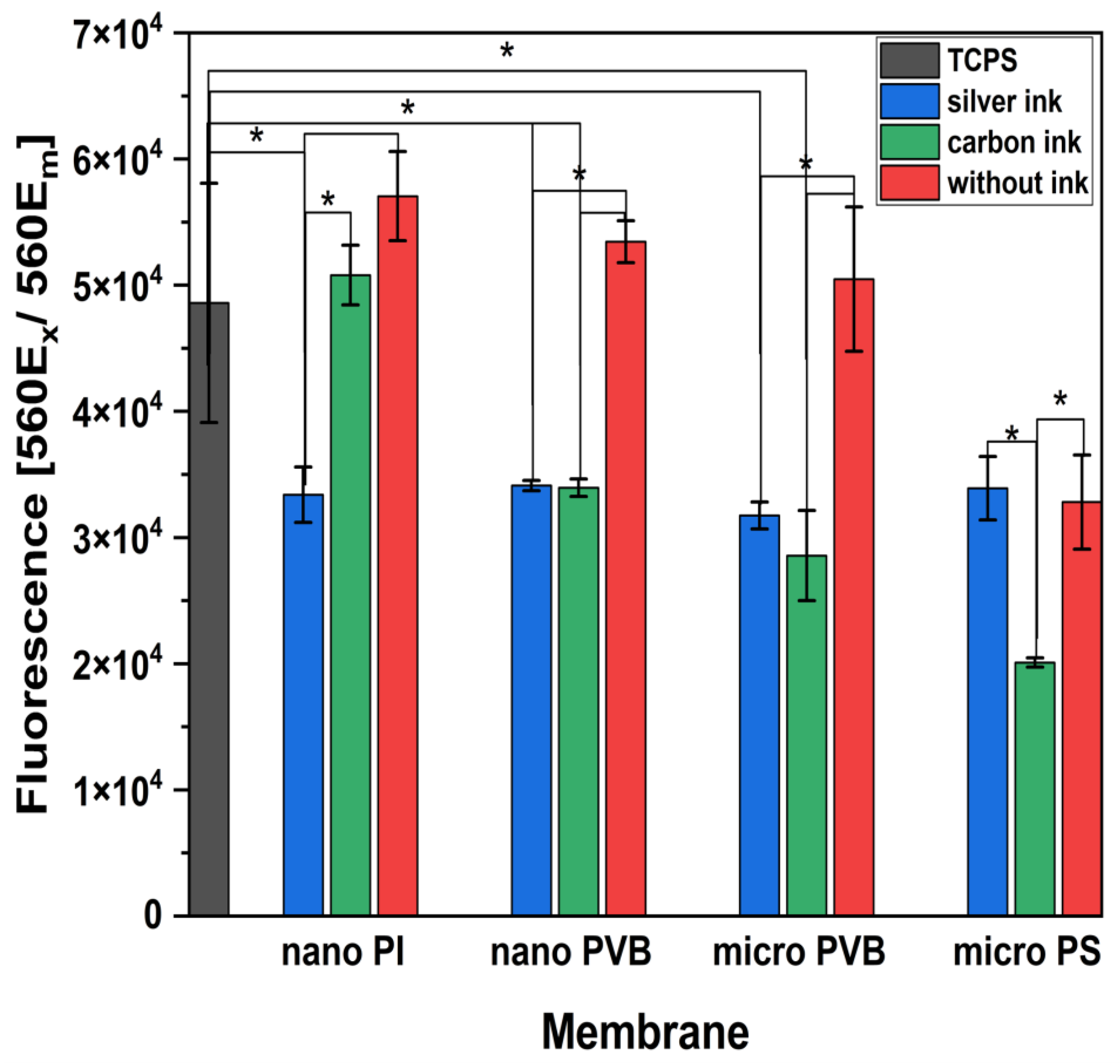
3.3. Cytotoxicity
4. Conclusions
Author Contributions
Funding
Institutional Review Board Statement
Informed Consent Statement
Data Availability Statement
Acknowledgments
Conflicts of Interest
References
- Hou, Z.; Lu, H.; Li, Y.; Yang, L.; Gao, Y. Direct Ink Writing of Materials for Electronics-Related Applications: A Mini Review. Front. Mater. 2021, 8, 1–8. [Google Scholar] [CrossRef]
- Abas, M.; Salman, Q.; Khan, A.M.; Rahman, K. Direct ink writing of flexible electronic circuits and their characterization. J. Braz. Soc. Mech. Sci. Eng. 2019, 41, 563. [Google Scholar] [CrossRef]
- Dijksman, J.F.; Duineveld, P.C.; Hack, M.J.J.; Pierik, A.; Rensen, J.; Rubingh, J.-E.; Schram, I.; Vernhout, M.M. Precision ink jet printing of polymer light emitting displays. J. Mater. Chem. 2006, 17, 511–522. [Google Scholar] [CrossRef]
- Dijksman, J.F.; Stachewicz, U. On-demand Electrohydrodynamic Jetting of an Ethylene Glycol and Water Mixture—System of Controlled Picoliter Fluid Deposition. In Proceedings of the NIP & Digital Fabrication Conference, Saint Francisco, CA, USA, 29 September–3 October 2021; pp. 5–27. [Google Scholar] [CrossRef]
- Rosell-Llompart, J.; de la Mora, J.F. Generation of monodisperse droplets 0.3 to 4 μm in diameter from electrified cone-jets of highly conducting and viscous liquids. J. Aerosol Sci. 1994, 25, 1093–1119. [Google Scholar] [CrossRef]
- Wilkinson, N.J.; Kay, R.; Harris, R.A. Electrohydrodynamic and Aerosol Jet Printing for the Copatterning of Polydimethylsiloxane and Graphene Platelet Inks. Adv. Mater. Technol. 2020, 5, 2000148. [Google Scholar] [CrossRef]
- Nge, T.T.; Nogi, M.; Suganuma, K. Electrical functionality of inkjet-printed silver nanoparticle conductive tracks on nanostructured paper compared with those on plastic substrates. J. Mater. Chem. C 2013, 1, 5235–5243. [Google Scholar] [CrossRef]
- Tortorich, R.P.; Shamkhalichenar, H.; Choi, J.-W. Inkjet-Printed and Paper-Based Electrochemical Sensors. Appl. Sci. 2018, 8, 288. [Google Scholar] [CrossRef] [Green Version]
- Kawase, T.; Shimoda, T.; Newsome, C.; Sirringhaus, H.; Friend, R.H. Inkjet printing of polymer thin film transistors. Thin Solid Films 2003, 438–439, 279–287. [Google Scholar] [CrossRef]
- Wei, Z.; Chen, H.; Yan, K.; Yang, S. Inkjet Printing and Instant Chemical Transformation of a CH3NH3PbI3/Nanocarbon Electrode and Interface for Planar Perovskite Solar Cells. Angew. Chem. Int. Ed. 2014, 53, 13239–13243. [Google Scholar] [CrossRef]
- Zhang, Y.; Shi, G.; Qin, J.; Lowe, S.E.; Zhang, S.; Zhao, H.; Zhong, Y.L. Recent Progress of Direct Ink Writing of Electronic Components for Advanced Wearable Devices. ACS Appl. Electron. Mater. 2019, 1, 1718–1734. [Google Scholar] [CrossRef]
- Wiklund, J.; Karakoç, A.; Palko, T.; Yiğitler, H.; Ruttik, K.; Jäntti, R.; Paltakari, J. A Review on Printed Electronics: Fabrication Methods, Inks, Substrates, Applications and Environmental Impacts. J. Manuf. Mater. Process. 2021, 5, 89. [Google Scholar] [CrossRef]
- Abdolmaleki, H.; Kidmose, P.; Agarwala, S. Droplet-Based Techniques for Printing of Functional Inks for Flexible Physical Sensors. Adv. Mater. 2021, 33, 2006792. [Google Scholar] [CrossRef] [PubMed]
- Pandhi, T.; Chandnani, A.; Subbaraman, H.; Estrada, D. A Review of Inkjet Printed Graphene and Carbon Nanotubes Based Gas Sensors. Sensors 2020, 20, 5642. [Google Scholar] [CrossRef]
- Bhuiyan, E.H.; Behroozfar, A.; Daryadel, S.; Moreno, S.; Morsali, S.; Minary-Jolandan, M. A Hybrid Process for Printing Pure and High Conductivity Nanocrystalline Copper and Nickel on Flexible Polymeric Substrates. Sci. Rep. 2019, 9, 19032. [Google Scholar] [CrossRef] [PubMed] [Green Version]
- Mhetre, S.; Carr, W.; Radhakrishnaiah, P. On the relationship between ink-jet printing quality of pigment ink and the spreading behavior of ink drops. J. Text. Inst. 2010, 101, 423–430. [Google Scholar] [CrossRef]
- Öhlund, T.; Örtegren, J.; Forsberg, S.; Nilsson, H.-E. Paper surfaces for metal nanoparticle inkjet printing. Appl. Surf. Sci. 2012, 259, 731–739. [Google Scholar] [CrossRef]
- Lemarchand, J.; Bridonneau, N.; Battaglini, N.; Carn, F.; Mattana, G.; Piro, B.; Zrig, S.; Noël, V. Challenges, Prospects, and Emerging Applications of Inkjet-Printed Electronics: A Chemist’s Point of View. Angew. Chem. Int. Ed. 2022, 61, e202200166. [Google Scholar] [CrossRef]
- Jansson, E.; Lyytikäinen, J.; Tanninen, P.; Eiroma, K.; Leminen, V.; Immonen, K.; Hakola, L. Suitability of Paper-Based Substrates for Printed Electronics. Materials 2022, 15, 957. [Google Scholar] [CrossRef]
- Genina, N.; Janßen, E.M.; Breitenbach, A.; Breitkreutz, J.; Sandler, N. Evaluation of different substrates for inkjet printing of rasagiline mesylate. Eur. J. Pharm. Biopharm. 2013, 85, 1075–1083. [Google Scholar] [CrossRef]
- Khan, S.; Ali, S.; Khan, A.; Wang, B.; Al-Ansari, T.; Bermak, A. Substrate Treatment Evaluation and Their Impact on Printing Results for Wearable Electronics. Front. Electron. 2021, 2, 1–10. [Google Scholar] [CrossRef]
- Agarwala, S.; Goh, G.L.; Dinh Le, T.-S.; An, J.; Peh, Z.K.; Yeong, W.Y.; Kim, Y.-J. Wearable Bandage-Based Strain Sensor for Home Healthcare: Combining 3D Aerosol Jet Printing and Laser Sintering. ACS Sens. 2019, 4, 218–226. [Google Scholar] [CrossRef]
- Karakurt, I.; Lin, L. 3D printing technologies: Techniques, materials, and post-processing. Curr. Opin. Chem. Eng. 2020, 28, 134–143. [Google Scholar] [CrossRef]
- Zhang, T.; Mu, X.; Jiang, M.; Huang, L.; Zhao, J. Use of electrospun fiber membrane as the screen printing stencil for high definition printing. Mater. Res. Express 2019, 6, 1150h7. [Google Scholar] [CrossRef]
- Huang, L.; Bui, N.-N.; Manickam, S.S.; McCutcheon, J.R. Controlling electrospun nanofiber morphology and mechanical properties using humidity. J. Polym. Sci. Part B Polym. Phys. 2011, 49, 1734–1744. [Google Scholar] [CrossRef]
- Rashid, T.U.; Gorga, R.E.; Krause, W.E. Mechanical Properties of Electrospun Fibers—A Critical Review. Adv. Eng. Mater. 2021, 23, 2100153. [Google Scholar] [CrossRef]
- Costa, T.; Ribeiro, A.; Machado, R.; Ribeiro, C.; Lanceros-Mendez, S.; Cavaco-Paulo, A.; Almeida, A.; das Neves, J.; Lúcio, M.; Viseu, T. Polymeric Electrospun Fibrous Dressings for Topical Co-delivery of Acyclovir and Omega-3 Fatty Acids. Front. Bioeng. Biotechnol. 2019, 7, 390. [Google Scholar] [CrossRef] [Green Version]
- Luraghi, A.; Peri, F.; Moroni, L. Electrospinning for drug delivery applications: A review. J. Control. Release 2021, 334, 463–484. [Google Scholar] [CrossRef]
- Al-Hazeem, N.Z. Effect of the Distance between the Needle Tip and the Collector on Nanofibers Morphology. Nanomed. Nanotechnol. 2020, 5, 1–5. [Google Scholar] [CrossRef]
- Kenawy, E.-R.; Abdel-Hay, F.I.; El-Newehy, M.H.; Wnek, G.E. Processing of polymer nanofibers through electrospinning as drug delivery systems. Mater. Chem. Phys. 2009, 113, 296–302. [Google Scholar] [CrossRef]
- Chauhan, D.; Singh, N.; Afreen, S.; Talreja, N.; Ashfaq, M.; Sankararamakrishnan, N.; Chaudhary, G.R. A thermoresponsive CA-PNIPAM based electrospun nanofibrous membrane for oil/water separation. New J. Chem. 2022, 46, 18984–18989. [Google Scholar] [CrossRef]
- Babu, A.; Aazem, I.; Walden, R.; Bairagi, S.; Mulvihill, D.M.; Pillai, S.C. Electrospun nanofiber based TENGs for wearable electronics and self-powered sensing. Chem. Eng. J. 2022, 452, 139060. [Google Scholar] [CrossRef]
- Hou, X.; Zhou, Y.; Liu, Y.; Wang, L.; Wang, J. Coaxial electrospun flexible PANI//PU fibers as highly sensitive pH wearable sensor. J. Mater. Sci. 2020, 55, 16033–16047. [Google Scholar] [CrossRef]
- Lu, T.; Deng, Y.; Cui, J.; Cao, W.; Qu, Q.; Wang, Y.; Xiong, R.; Ma, W.; Lei, J.; Huang, C. Multifunctional Applications of Blow-Spinning Setaria viridis Structured Fibrous Membranes in Water Purification. ACS Appl. Mater. Interfaces 2021, 13, 22874–22883. [Google Scholar] [CrossRef]
- Liu, L.; Xu, W.; Ding, Y.; Agarwal, S.; Greiner, A.; Duan, G. A review of smart electrospun fibers toward textiles. Compos. Commun. 2020, 22, 100506. [Google Scholar] [CrossRef]
- Ding, B. Electrospinning, fibers and textiles: A new driving force for global development. e-Polymers 2017, 17, 209–210. [Google Scholar] [CrossRef]
- Chinnappan, A.; Baskar, C.; Baskar, S.; Ratheesh, G.; Ramakrishna, S. An overview of electrospun nanofibers and their application in energy storage, sensors and wearable/flexible electronics. J. Mater. Chem. C 2017, 5, 12657–12673. [Google Scholar] [CrossRef]
- Wei, L.; Sun, R.; Liu, C.; Xiong, J.; Qin, X. Mass production of nanofibers from needleless electrospinning by a novel annular spinneret. Mater. Des. 2019, 179, 107885. [Google Scholar] [CrossRef]
- Ivanoska-Dacikj, A.; Stachewicz, U. Smart textiles and wearable technologies—Opportunities offered in the fight against pandemics in relation to current COVID-19 state. Rev. Adv. Mater. Sci. 2020, 59, 487–505. [Google Scholar] [CrossRef]
- Zainuddin, S.; Scheibel, T. Continuous Yarn Electrospinning. Textiles 2022, 2, 124–141. [Google Scholar] [CrossRef]
- Yan, T.; Shi, Y.; Zhuang, H.; Lin, Y.; Lu, D.; Cao, S.; Zhu, L. Electrospinning Mechanism of Nanofiber Yarn and Its Multiscale Wrapping Yarn. Polymers 2021, 13, 3189. [Google Scholar] [CrossRef]
- Lee, M.W.; An, S.; Latthe, S.S.; Lee, C.; Hong, S.; Yoon, S.S. Electrospun Polystyrene Nanofiber Membrane with Superhydrophobicity and Superoleophilicity for Selective Separation of Water and Low Viscous Oil. ACS Appl. Mater. Interfaces 2013, 5, 10597–10604. [Google Scholar] [CrossRef]
- Yang, J.; Wang, K.; Yu, D.-G.; Yang, Y.; Bligh, S.W.A.; Williams, G.R. Electrospun Janus nanofibers loaded with a drug and inorganic nanoparticles as an effective antibacterial wound dressing. Mater. Sci. Eng. C 2020, 111, 110805. [Google Scholar] [CrossRef]
- Soliman, S.; Sant, S.; Nichol, J.W.; Khabiry, M.; Traversa, E.; Khademhosseini, A. Controlling the porosity of fibrous scaffolds by modulating the fiber diameter and packing density. J. Biomed. Mater. Res. Part A 2011, 96A, 566–574. [Google Scholar] [CrossRef]
- Haider, A.; Haider, S.; Kang, I.-K. A comprehensive review summarizing the effect of electrospinning parameters and potential applications of nanofibers in biomedical and biotechnology. Arab. J. Chem. 2018, 11, 1165–1188. [Google Scholar] [CrossRef]
- Eichhorn, S.; Sampson, W.W. Relationships between specific surface area and pore size in electrospun polymer fibre networks. J. R. Soc. Interface 2009, 7, 641–649. [Google Scholar] [CrossRef] [Green Version]
- Szewczyk, P.K.; Ura, D.P.; Metwally, S.; Knapczyk-Korczak, J.; Gajek, M.; Marzec, M.M.; Bernasik, A.; Stachewicz, U. Roughness and Fiber Fraction Dominated Wetting of Electrospun Fiber-Based Porous Meshes. Polymers 2019, 11, 34. [Google Scholar] [CrossRef] [Green Version]
- Ura, D.P.; Stachewicz, U. The Significance of Electrical Polarity in Electrospinning: A Nanoscale Approach for the Enhancement of the Polymer Fibers’ Properties. Macromol. Mater. Eng. 2022, 307, 2100843. [Google Scholar] [CrossRef]
- Cui, W.; Li, X.; Zhou, S.; Weng, J. Degradation patterns and surface wettability of electrospun fibrous mats. Polym. Degrad. Stab. 2008, 93, 731–738. [Google Scholar] [CrossRef]
- Stachewicz, U.; Barber, A.H. Enhanced Wetting Behavior at Electrospun Polyamide Nanofiber Surfaces. Langmuir 2011, 27, 3024–3029. [Google Scholar] [CrossRef]
- Lee, S.J.; Heo, D.N.; Heo, M.; Noh, M.H.; Lee, D.; Park, S.; Moon, J.-H.; Kwon, I.K. Most simple preparation of an inkjet printing of silver nanoparticles on fibrous membrane for water purification: Technological and commercial application. J. Ind. Eng. Chem. 2017, 46, 273–278. [Google Scholar] [CrossRef]
- Najafabadi, A.H.; Tamayol, A.; Annabi, N.; Ochoa, M.; Mostafalu, P.; Akbari, M.; Nikkhah, M.; Rahimi, R.; Dokmeci, M.R.; Sonkusale, S.; et al. Biodegradable Nanofibrous Polymeric Substrates for Generating Elastic and Flexible Electronics. Adv. Mater. 2014, 26, 5823–5830. [Google Scholar] [CrossRef]
- Krysiak, Z.J.; Kaniuk, Ł.; Metwally, S.; Szewczyk, P.K.; Sroczyk, E.A.; Peer, P.; Lisiecka-Graca, P.; Bailey, R.J.; Bilotti, E.; Stachewicz, U. Nano- and Microfiber PVB Patches as Natural Oil Carriers for Atopic Skin Treatment. ACS Appl. Bio Mater. 2020, 3, 7666–7676. [Google Scholar] [CrossRef] [PubMed]
- Sroczyk, E.A.; Berniak, K.; Jaszczur, M.; Stachewicz, U. Topical electrospun patches loaded with oil for effective gamma linoleic acid transport and skin hydration towards atopic dermatitis skincare. Chem. Eng. J. 2021, 429, 132256. [Google Scholar] [CrossRef]
- Krysiak, Z.J.; Knapczyk-Korczak, J.; Maniak, G.; Stachewicz, U. Moisturizing effect of skin patches with hydrophobic and hydrophilic electrospun fibers for atopic dermatitis. Colloids Surf. B Biointerfaces 2020, 199, 111554. [Google Scholar] [CrossRef]
- Krysiak, Z.J.; Szewczyk, P.K.; Berniak, K.; Sroczyk, E.A.; Boratyn, E.; Stachewicz, U. Stretchable skin hydrating PVB patches with controlled pores’ size and shape for deliberate evening primrose oil spreading, transport and release. Biomater. Adv. 2022, 136, 212786. [Google Scholar] [CrossRef]
- Nanosilver Ink—Aqueous Dispersions for Inkjet Printing. 2018. Available online: https://www.matweb.com/search/datasheet.aspx?matguid=76dd8b5d3e624bbba5aa4d08eaee3860 (accessed on 20 October 2022).
- Carbon Ink—Aqueous Dispersion for Inkjet Printing. 2020. Available online: https://www.novacentrix.com/datasheet/Metalon-JR-700LV-TDS.pdf (accessed on 20 October 2022).
- Krysiak, Z.J.; Gawlik, M.Z.; Knapczyk-Korczak, J.; Kaniuk, Ł.; Stachewicz, U. Hierarchical Composite Meshes of Electrospun PS Microfibers with PA6 Nanofibers for Regenerative Medicine. Materials 2020, 13, 1974. [Google Scholar] [CrossRef] [PubMed] [Green Version]
- Yonemoto, Y.; Kunugi, T. Analytical consideration of liquid droplet impingement on solid surfaces. Sci. Rep. 2017, 7, 2362. [Google Scholar] [CrossRef] [PubMed] [Green Version]
- Knapczyk-Korczak, J.; Ura, D.P.; Gajek, M.; Marzec, M.M.; Berent, K.; Bernasik, A.; Chiverton, J.P.; Stachewicz, U. Fiber-Based Composite Meshes with Controlled Mechanical and Wetting Properties for Water Harvesting. ACS Appl. Mater. Interfaces 2020, 12, 1665–1676. [Google Scholar] [CrossRef]
- Bagrov, D.; Perunova, S.; Pavlova, E.; Klinov, D. Wetting of electrospun nylon-11 fibers and mats. RSC Adv. 2021, 11, 11373–11379. [Google Scholar] [CrossRef]
- Kwon, K.-S.; Rahman, K.; Phung, T.H.; Hoath, S.; Jeong, S.; Kim, J.S. Review of digital printing technologies for electronic materials. Flex. Print. Electron. 2020, 5, 043003. [Google Scholar] [CrossRef]
- Biswas, S.; Gawande, S.; Bromberg, V.; Sun, Y. Effects of Particle Size and Substrate Surface Properties on Deposition Dynamics of Inkjet-Printed Colloidal Drops for Printable Photovoltaics Fabrication. J. Sol. Energy Eng. 2010, 132, 0210101–0210107. [Google Scholar] [CrossRef]
- Ruediger, T.; Berg, A.; Guellmar, A.; Rode, C.; Schnabelrauch, M.; Urbanek, A.; Wagner, K.; Wyrwa, R.; Kinne, R.W.; Sigusch, B.W. Cytocompatibility of polymer-based periodontal bone substitutes in gingival fibroblast and MC3T3 osteoblast cell cultures. Dent. Mater. 2012, 28, e239–e249. [Google Scholar] [CrossRef] [PubMed]
- Polyakov, I.; Vaganov, G.; Didenko, A.; Ivan’Kova, E.; Popova, E.; Nashchekina, Y.; Elokhovskiy, V.; Svetlichnyi, V.; Yudin, V. Development and Processing of New Composite Materials Based on High-Performance Semicrystalline Polyimide for Fused Filament Fabrication (FFF) and Their Biocompatibility. Polymers 2022, 14, 3803. [Google Scholar] [CrossRef]
- Albers, C.E.; Hofstetter, W.; Siebenrock, K.A.; Landmann, R.; Klenke, F.M. In vitro cytotoxicity of silver nanoparticles on osteoblasts and osteoclasts at antibacterial concentrations. Nanotoxicology 2013, 7, 30–36. [Google Scholar] [CrossRef] [PubMed]


| Electrospun Membrane | Voltage Applied Needle–Collector [kV] | Distance Needle–Collector [cm] | Flow Rate [mL·h−1] | Temperature [°C] | Humidity [%] |
|---|---|---|---|---|---|
| nano PI | 16 | 15 | 0.3 | 22 | 60 |
| nano PVB | 14–15 | 15 | 1.0 | 25 | 30 |
| micro PVB | 10–11 | 15 | 1.5 | 25 | 30 |
| micro PS | 11–12 | 20 | 1.5 | 25 | 40 |
| Membrane | Silver Ink | Carbon Ink | ||
|---|---|---|---|---|
| Voltage [V] | Distance between the Platen and Cartridges [μm] | Voltage [V] | Distance between the Platen and Cartridges [μm] | |
| nano PI | 32 | 1000 | 40 | 1000 |
| nano PVB | 32 | 700 | 40 | 1000 |
| micro PVB | 32 | 700 | 40 | 1000 |
| micro PS | 32 | 1200 | 40 | 1200 |
Publisher’s Note: MDPI stays neutral with regard to jurisdictional claims in published maps and institutional affiliations. |
© 2022 by the authors. Licensee MDPI, Basel, Switzerland. This article is an open access article distributed under the terms and conditions of the Creative Commons Attribution (CC BY) license (https://creativecommons.org/licenses/by/4.0/).
Share and Cite
Krysiak, Z.J.; Abdolmaleki, H.; Agarwala, S.; Stachewicz, U. Inkjet Printing of Electrodes on Electrospun Micro- and Nanofiber Hydrophobic Membranes for Flexible and Smart Textile Applications. Polymers 2022, 14, 5043. https://doi.org/10.3390/polym14225043
Krysiak ZJ, Abdolmaleki H, Agarwala S, Stachewicz U. Inkjet Printing of Electrodes on Electrospun Micro- and Nanofiber Hydrophobic Membranes for Flexible and Smart Textile Applications. Polymers. 2022; 14(22):5043. https://doi.org/10.3390/polym14225043
Chicago/Turabian StyleKrysiak, Zuzanna J., Hamed Abdolmaleki, Shweta Agarwala, and Urszula Stachewicz. 2022. "Inkjet Printing of Electrodes on Electrospun Micro- and Nanofiber Hydrophobic Membranes for Flexible and Smart Textile Applications" Polymers 14, no. 22: 5043. https://doi.org/10.3390/polym14225043